EP3929592B1 - Automatisierter analysator - Google Patents
Automatisierter analysator Download PDFInfo
- Publication number
- EP3929592B1 EP3929592B1 EP20758550.6A EP20758550A EP3929592B1 EP 3929592 B1 EP3929592 B1 EP 3929592B1 EP 20758550 A EP20758550 A EP 20758550A EP 3929592 B1 EP3929592 B1 EP 3929592B1
- Authority
- EP
- European Patent Office
- Prior art keywords
- cleaning
- cleaning fluid
- solenoid valve
- probe
- vacuum
- Prior art date
- Legal status (The legal status is an assumption and is not a legal conclusion. Google has not performed a legal analysis and makes no representation as to the accuracy of the status listed.)
- Active
Links
Images


Classifications
-
- G—PHYSICS
- G01—MEASURING; TESTING
- G01N—INVESTIGATING OR ANALYSING MATERIALS BY DETERMINING THEIR CHEMICAL OR PHYSICAL PROPERTIES
- G01N35/00—Automatic analysis not limited to methods or materials provided for in any single one of groups G01N1/00 - G01N33/00; Handling materials therefor
- G01N35/10—Devices for transferring samples or any liquids to, in, or from, the analysis apparatus, e.g. suction devices, injection devices
- G01N35/1004—Cleaning sample transfer devices
-
- G—PHYSICS
- G01—MEASURING; TESTING
- G01N—INVESTIGATING OR ANALYSING MATERIALS BY DETERMINING THEIR CHEMICAL OR PHYSICAL PROPERTIES
- G01N35/00—Automatic analysis not limited to methods or materials provided for in any single one of groups G01N1/00 - G01N33/00; Handling materials therefor
- G01N35/10—Devices for transferring samples or any liquids to, in, or from, the analysis apparatus, e.g. suction devices, injection devices
- G01N35/1002—Reagent dispensers
Definitions
- the present invention relates to an automatic analyzer that analyzes a liquid sample such as blood, urine and the like to determine a concentration of a predetermined component contained therein, and the like.
- the amount of cleaning fluid adheres to the exterior of the probe which has been cleaned is greater in comparison to the former case where only the leading end is cleaned. If the next sample is aspirated by the probe with the cleaning fluid adhering to its exterior, the sample will be diluted with the cleaning fluid. Therefore, the cleaning fluid is required to be removed speedily by vacuum suction.
- Patent Literature 1 may be adequate as long as the amount of waste fluid produced by cleaning a sample probe is small.
- the waste fluid collects in the vacuum tank and therefore periodical removal of waste fluid is required.
- the removal of waste fluid produces a need to draw anew vacuum on the vacuum tank. Therefore, if there is a likelihood of a large amount of waste fluid, the cleaning drying bath and the vacuum tank are desirably connected to each other via a vacuum bottle to prevent the cleaning fluid (waste fluid) as much as possible from being drawn into the vacuum tank by vacuum suction.
- the amount of waste fluid produced by cleaning the sample probe is not much in comparison to, for example, the amount of waste fluid discharged from the reaction container cleaning mechanism.
- Fig. 1 is a perspective view of an automatic analyzer.
- the automatic analyzer is an apparatus used to dispense a sample and a reagent into a plurality of reaction containers 2 to initiate a reaction between them, and then measure the reacted liquid.
- the automatic analyzer includes a reaction disk 1, a reagent disk 9, a sample transport mechanism 17, reagent dispense mechanisms 7, 8, reagent syringes 18, 18a, sample dispense mechanisms 11, 12, sample syringes 19, 19a, a cleaning mechanism 3, a light source 4a, a spectrophotometer 4, agitation mechanisms 5, 6, a cleaning pump 20, cleaning baths 13, 14, 30, 31, 32, 33, a vacuum suction port 40, and a controller 21.
- a plurality of reagent bottles 10 is capable of being loaded on the circular circumference of the reagent disk 9.
- the reagent disk 9 is held at cool temperatures.
- the rotatable and vertical movable reagent dispense mechanisms 7, 8 are installed between the reaction disk 1 and the reagent disk 9.
- the reagent dispense mechanisms 7, 8 include reagent probes 7a, 8a connected to the reagent syringes 18, 18a, respectively. Each of the reagent probes 7a, 8a moves along an arc around the rotational axis of the corresponding reagent dispense mechanism 7, 8 in order to access the reagent disk 9 for dispensing of a reagent from the reagent bottle 10 to the reaction container 2.
- the cleaning mechanism 3 that cleans only the reaction containers after use in measurement; agitation mechanisms 5, 6 that perform agitation of a liquid mixture (reaction liquid) of a reagent and a sample in the reaction container; and the light source 4a and the spectrophotometer 4 that irradiate the liquid mixture (reaction liquid) in the reaction container with light and measures the absorbance, for example.
- the cleaning pump 20 is connected to the cleaning mechanism 3.
- the cleaning baths 13, 14, 33, 32, 31, 30 are disposed respectively within operating ranges of the sample dispense mechanisms 11, 12, the reagent dispense mechanisms 7, 8 and the agitation mechanisms 5, 6.
- Each mechanism of the automatic analyzer is connected to and controlled by the controller 21.
- the sample probe 11a aspirating a sample in the sample container 15 is for aspiration from an upper portion of the sample container 15, and the sample probe 12a is for aspiration from the vicinity of the bottom of the sample container 15. Because of this, for the sample probe 12a which has been used to dispense a sample, a need arises to clean a wide range of the sample probe in the cleaning bath 14 in order to prevent contamination between samples. After the cleaning of the wide range, because a large amount cleaning fluid adheres to the sample probe 12a, the vacuum suction port 40 is installed in the cleaning bath 14 so that the cleaning fluid adhering to the sample probe 12a is removed to prevent the sample from being diluted with the cleaning fluid.
- Fig. 2 illustrates the structure of the cleaning bath 14, in which a section view, a top view and a side view are shown.
- a drainage tube 43 and the vacuum suction port 40 are installed in the bottom of a bath 42.
- a cleaning fluid outlet 41 is also installed in the vicinity of the bath 42.
- the sample probe 12a is inserted into the bath 42 in the vicinity of the cleaning fluid outlet 41, and while the sample probe 12a is being moved up and down, the entire contaminated range of the exterior of the sample probe 12a is cleaned up.
- the cleaning fluid used for cleaning is discharged from the drainage tube 43.
- the sample probe 12a is moved to the vacuum suction port 40, and then is moved up and down to remove the cleaning fluid adhering to the sample probe 12a.
- the vacuum suction port 40 when viewed from the top of the bath 42, the vacuum suction port 40 is installed in a different position from the position where the cleaning fluid is ejected from the cleaning fluid outlet 41, and the drainage tube 43 is installed in the position where the cleaning fluid is ejected from the cleaning fluid outlet 41. This minimizes the risk that a test sample adhering to the exterior of the sample probe 12a enters the vacuum suction port 40.
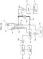
- Fig. 3B illustrates another channel configuration of the cleaning bath 14 (second comparative example).
- a point of difference from the channel configuration in Fig. 3A is that a vacuum bottle 56 is disposed to prevent the cleaning fluid adhering to the side face of the sample probe 12a from being accumulated directly in the vacuum tank 55. The cleaning fluid adhering to the sample probe 12a is temporarily stored in the vacuum bottle 56. Then, a third solenoid valve 50c installed between the vacuum bottle 56 and the drain 53 is opened for discharge into the drain 53. This eliminates a situation in which the cleaning fluid collects in the vacuum tank 55. However, as in the case of the second solenoid valve 50b in Fig. 3A , there still remains the risk of dust and/or the like being caught in the third solenoid valve 50c. Decreasing the hermetic performance of the third solenoid valve 50c may give rise to a defective condition such as a reduction in vacuum suction power and backflow of the cleaning fluid from the drain 53 toward the vacuum bottle 56.
- Fig. 6 illustrates an example of the maintenance operation in which the interior cleaning operation for the sample probe 12a is utilized to clean the vacuum bottle 56 and the third solenoid valve 50c.
- Fig. 6 illustrates a time chart for such maintenance operation. If, in the maintenance operation, detergent is aspirated into the sample probe 12a for interior cleaning, this is also effective in cleaning the vacuum bottle 56 and the third solenoid valve 50c.
- a detergent bottle is disposed between the reaction disk 1 and the sample transport mechanism 17, and the sample probe 12a aspirates the detergent from the detergent bottle. After the sample probe 12a is moved to the vacuum suction port 40, the descent operation is performed.
- the second solenoid valve 50b is turned to Open, whereby the cleaning fluid located from the cleaning fluid outlet 41 to the branch point 61 is able to be stored in the vacuum bottle 56 via the bypass passage 62.
- the third solenoid valve 50c is turned to Open, the cleaning fluid stored in the vacuum bottle 56 is discharged to the drain 53, thereby making it possible to wash the valve seat of the third solenoid valve 50c.
- the use of detergent in the interior cleaning operation is optional, and similar operation to that in Fig. 6 is performed in the interior cleaning operation during the analysis operation of the automatic analyzer, whereby the cleaning fluid discharged in the interior cleaning operation for a sample probe is able to be utilized for the cleaning operation for a solenoid valve.
- the third solenoid valve 50c is kept clean and the solenoid valve can be prevented from having a malfunction due to dust and/or the like.
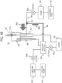
- the movement of the cleaning fluid in the vacuum suction operation is described below with reference to Fig. 7C .
- the sample probe 12a is moved to the vacuum suction port 40, and the fourth solenoid valve 50d and the second solenoid valve 50b are turned in this order to Open. Then, the sample probe 12a is moved up and down to remove the cleaning fluid.
- a cleaning fluid 60w'and a cleaning fluid 40w' are drawn into the vacuum bottle 56 by the vacuum suction operation, the cleaning fluid 60w' collecting in an area from the cleaning fluid outlet 41 to the branch point 61 when the exterior of the sample probe 12a is cleaned, the cleaning fluid 40w' adhering to the side face of the sample probe 12a.
- the cleaning fluid stored in the vacuum bottle 56 after the completion of the drying operation for the sample probe 12a is the sum of cleaning fluids 60w' and 40w', and thus, with this channel configuration, a large amount of cleaning fluid is also able to be stored in the vacuum bottle 56 in comparison with the case of the cleaning fluid 40w' in the second comparative example ( Fig. 3B ).
- the third solenoid valve 50c is turned to Open after the completion of the drying operation for the sample probe 12a.
- This makes it possible to wash the valve seat of the third solenoid valve 50c with the cleaning fluid stored in the vacuum bottle 56, so that the solenoid valve can be prevented from having a malfunction due to dust and/or the like.
- the cleaning fluid supplied from the cleaning tank 51 is ejected directly from the cleaning fluid outlet 41, so that a further reduction in exterior cleaning time is enabled.
- the sample probe is not required to be moved up and down because of a small cleaning range, the cleaning fluid adhering to the side face of the sample probe is removed at the vacuum suction position. Therefore, the advantageous effects of the present examples are not subject to limitations by the cleaning operation for the sample probe.
Landscapes
- Physics & Mathematics (AREA)
- Health & Medical Sciences (AREA)
- Life Sciences & Earth Sciences (AREA)
- Chemical & Material Sciences (AREA)
- Analytical Chemistry (AREA)
- Biochemistry (AREA)
- General Health & Medical Sciences (AREA)
- General Physics & Mathematics (AREA)
- Immunology (AREA)
- Pathology (AREA)
- Automatic Analysis And Handling Materials Therefor (AREA)
Claims (12)
- Automatischer Analysator, umfassend:ein Reinigungsbad (14), das einen Reinigungsflüssigkeitsauslass (41), aus dem Reinigungsflüssigkeit zur Reinigung der Außenseite einer Sonde austritt, und einen Vakuumsauganschluss (40) aufweist, in den die Sonde eingeführt wird;einen Reinigungstank (51), der die Reinigungsflüssigkeit lagert;einen Vakuumtank (55);eine Vakuumpumpe (54), die so konfiguriert ist, dass sie bewirkt, dass der Vakuumtank (55) unter Unterdruck in Bezug auf den atmosphärischen Druck gesetzt wird;eine Vakuumflasche (56), die zwischen dem Vakuumsauganschluss (40) und dem Vakuumtank (55) angeordnet ist;eine Pumpe (52), die so konfiguriert ist, dass sie die im Reinigungstank (51) gelagerte Reinigungsflüssigkeit zum Reinigungsflüssigkeitsauslass (41) fördert;ein erstes Magnetventil (50a);ein zweites Magnetventil (50b), das zwischen dem Vakuumtank (55) und der Vakuumflasche (56) installiert ist;ein drittes Magnetventil (50c), das zwischen der Vakuumflasche (56) und einem Abfluss (53) installiert ist;einen ersten Kanal, der eine Verbindung zwischen dem Vakuumsauganschluss (40) und der Vakuumflasche (56) herstellt; undeine Steuerung (21), die so konfiguriert ist, dass sie einen jeweiligen Mechanismus des automatischen Analysators steuert;dadurch gekennzeichnet,dass das erste Magnetventil (50a) zwischen der Pumpe (52) und dem Reinigungsflüssigkeitsauslass (41) installiert ist; unddurch einen zweiten Kanal und einen dritten Kanal (60), wobei der dritte Kanal (60) zwischen dem ersten Magnetventil (50a) und dem Reinigungsflüssigkeitsauslass (41) liegt und einen Verzweigungspunkt (61) aufweist, von dem aus der zweite Kanal, der eine Bypassleitung (62) ist, mit der Vakuumflasche (56) verbunden ist, wobei der Analysator so konfiguriert ist, dass:durch Öffnen des ersten Magnetventils (50a), während das zweite und das dritte Magnetventil (50b, 50c) geschlossen sind, die Reinigungsflüssigkeit aus dem Reinigungsflüssigkeitsauslass (41) ausgestoßen wird, unddurch Öffnen des zweiten Magnetventils (50b) bei geschlossenem ersten und dritten Magnetventil (50a, 50c) die Reinigungsflüssigkeit (40w, 62w) aus dem ersten Kanal und aus dem zweiten Kanal in die Vakuumflasche (56) fließt.
- Automatischer Analysator nach Anspruch 1,wobei das Reinigungsbad (14) ein Bad aufweist, in das die Reinigungsflüssigkeit aus dem Reinigungsflüssigkeitsauslass (41) abgeführt wird, undder Vakuumsauganschluss (40) in einem Boden des Bads (14) installiert ist und sich der Vakuumsauganschluss (40) bei Betrachtung des Bads von oben in einer anderen Position befindet als in einer Position, in der die Reinigungsflüssigkeit aus dem Reinigungsflüssigkeitsauslass (41) abgeführt wird.
- Automatischer Analysator nach Anspruch 1,
wobei die Steuerung so konfiguriert ist, dass sie das erste Magnetventil (50a) vor einer vorbestimmten Zeitspanne vor dem durch eine Sequenz definierten Startzeitpunkt der Reinigung der Außenseite der Sonde öffnet. - Automatischer Analysator nach Anspruch 3,
wobei die Steuerung so konfiguriert ist, dass sie das zweite Magnetventil (50b) nach Abschluss der Reinigung der Außenseite der Sonde öffnet und die Sonde in den Vakuumsauganschluss (40) einführt und dann die Sonde nach oben und unten bewegt, um die an der Außenseite der Sonde haftende Reinigungsflüssigkeit zu entfernen. - Automatischer Analysator nach Anspruch 4,
wobei die Steuerung so konfiguriert ist, dass sie das dritte Magnetventil (50c) öffnet, nachdem die Sonde aus dem Vakuumsauganschluss bewegt wurde. - Automatischer Analysator nach Anspruch 3,
wobei die Steuerung so konfiguriert ist, dass sie die Sonde für einen Innenreinigungsvorgang zum Vakuumsauganschluss (40) bewegt, um das Innere der Sonde zu reinigen. - Automatischer Analysator nach Anspruch 6,
wobei die Steuerung so konfiguriert ist, dass sie die Sonde veranlasst, ein Reinigungsmittel für den Innenreinigungsvorgang anzusaugen. - Automatischer Analysator nach Anspruch 6,
wobei die Steuerung so konfiguriert ist, dass sie das erste Magnetventil (50a) während des Innenreinigungsvorgangs für die Sonde öffnet. - Automatischer Analysator nach Anspruch 1,
wobei die Sonde eine Probensonde (12a) ist. - Automatischer Analysator nach Anspruch 4, der ein viertes Magnetventil (50d) umfasst, das in der Bypassleitung (62) installiert ist,
wobei die Steuerung so konfiguriert ist, dass sie das vierte Magnetventil (50d) während einer Zeitspanne schließt, in der die Außenseite der Sonde gereinigt wird, und nach Abschluss der Reinigung der Außenseite der Sonde die Steuerung so konfiguriert ist, dass sie das vierte Magnetventil (50d) vor dem zweiten Magnetventil (50b) öffnet. - Automatischer Analysator nach Anspruch 1,
wobei der Analysator so konfiguriert ist, dass durch Öffnen des zweiten Magnetventils (50b) die an einer Seitenfläche der Sonde anhaftende Reinigungsflüssigkeit (40w) aus dem ersten Kanal in die Vakuumflasche (56) fließt und die Reinigungsflüssigkeit (60w), die sich bei geschlossenem ersten Magnetventil (50a) in einem Bereich vom Reinigungsflüssigkeitsauslass (41) bis zum Verzweigungspunkt (61) angesammelt hat, und die Reinigungsflüssigkeit (62w), die sich in der Bypassleitung (62) angesammelt hat, aus dem zweiten Kanal in die Vakuumflasche (56) fließen. - Automatischer Analysator nach Anspruch 1,
wobei der Analysator so konfiguriert ist, dass das Öffnen und Schließen des zweiten Magnetventils (50b) funktionsmäßig in einem Zyklus für das Reinigungsbad (14) durchgeführt werden.
Applications Claiming Priority (2)
| Application Number | Priority Date | Filing Date | Title |
|---|---|---|---|
| JP2019026313 | 2019-02-18 | ||
| PCT/JP2020/003384 WO2020170751A1 (ja) | 2019-02-18 | 2020-01-30 | 自動分析装置 |
Publications (3)
| Publication Number | Publication Date |
|---|---|
| EP3929592A1 EP3929592A1 (de) | 2021-12-29 |
| EP3929592A4 EP3929592A4 (de) | 2022-10-26 |
| EP3929592B1 true EP3929592B1 (de) | 2024-11-27 |
Family
ID=72144241
Family Applications (1)
| Application Number | Title | Priority Date | Filing Date |
|---|---|---|---|
| EP20758550.6A Active EP3929592B1 (de) | 2019-02-18 | 2020-01-30 | Automatisierter analysator |
Country Status (5)
| Country | Link |
|---|---|
| US (1) | US12360132B2 (de) |
| EP (1) | EP3929592B1 (de) |
| JP (1) | JP6998492B2 (de) |
| CN (1) | CN113039440B (de) |
| WO (1) | WO2020170751A1 (de) |
Families Citing this family (2)
| Publication number | Priority date | Publication date | Assignee | Title |
|---|---|---|---|---|
| US12226776B2 (en) | 2021-11-04 | 2025-02-18 | Instrumentation Laboratory Company | Preparing substances in a medical diagnostic system |
| CN120677391A (zh) * | 2023-05-15 | 2025-09-19 | 株式会社日立高新技术 | 自动分析装置 |
Family Cites Families (15)
| Publication number | Priority date | Publication date | Assignee | Title |
|---|---|---|---|---|
| JPS5357893U (de) | 1976-10-16 | 1978-05-17 | ||
| JPH0478558U (de) * | 1990-11-21 | 1992-07-08 | ||
| JP3282248B2 (ja) | 1992-11-26 | 2002-05-13 | 株式会社島津製作所 | 生化学自動分析装置の洗浄装置 |
| CA2132270A1 (en) * | 1993-10-28 | 1995-04-29 | Erich Lerch | Automatic pipetting apparatus having a cleaning device |
| JP3873656B2 (ja) * | 2001-05-16 | 2007-01-24 | 株式会社日立製作所 | 自動分析装置 |
| JP4443271B2 (ja) * | 2004-03-12 | 2010-03-31 | 株式会社日立ハイテクノロジーズ | 自動分析装置 |
| JP2005308506A (ja) * | 2004-04-21 | 2005-11-04 | Hitachi High-Technologies Corp | 自動分析装置 |
| US7621282B2 (en) | 2004-06-17 | 2009-11-24 | Abbott Laboratories, Inc. | Probe washing cups and methods |
| US20080099057A1 (en) | 2006-10-27 | 2008-05-01 | Dade Behring Inc. | Method and Device for Cleaning a Liquid Aspiration and Dispense Probe |
| CN104903729B (zh) * | 2013-01-21 | 2018-05-22 | 株式会社日立高新技术 | 自动分析装置 |
| CN203299211U (zh) * | 2013-06-18 | 2013-11-20 | 东软安德医疗科技有限公司 | 一种全自动生化分析仪给排液系统 |
| JP6373879B2 (ja) * | 2014-01-27 | 2018-08-15 | 株式会社日立ハイテクノロジーズ | 自動分析装置 |
| CN108700610B (zh) | 2016-02-24 | 2022-09-27 | 株式会社日立高新技术 | 自动分析装置及清洗方法 |
| CN110300895B (zh) | 2017-02-24 | 2022-12-13 | 株式会社日立高新技术 | 自动分析装置 |
| JP6749857B2 (ja) | 2017-03-24 | 2020-09-02 | 株式会社日立ハイテク | 自動分析装置 |
-
2020
- 2020-01-30 JP JP2021501787A patent/JP6998492B2/ja active Active
- 2020-01-30 EP EP20758550.6A patent/EP3929592B1/de active Active
- 2020-01-30 US US17/276,952 patent/US12360132B2/en active Active
- 2020-01-30 CN CN202080005946.0A patent/CN113039440B/zh active Active
- 2020-01-30 WO PCT/JP2020/003384 patent/WO2020170751A1/ja not_active Ceased
Also Published As
| Publication number | Publication date |
|---|---|
| WO2020170751A1 (ja) | 2020-08-27 |
| CN113039440A (zh) | 2021-06-25 |
| EP3929592A4 (de) | 2022-10-26 |
| CN113039440B (zh) | 2024-11-26 |
| US12360132B2 (en) | 2025-07-15 |
| US20220034926A1 (en) | 2022-02-03 |
| JP6998492B2 (ja) | 2022-01-18 |
| JPWO2020170751A1 (ja) | 2021-10-07 |
| EP3929592A1 (de) | 2021-12-29 |
Similar Documents
| Publication | Publication Date | Title |
|---|---|---|
| JP6647288B2 (ja) | 自動分析装置及び方法 | |
| JP3590072B2 (ja) | 液体サンプル・プローブをクリーニングするための装置 | |
| EP1766418B1 (de) | Sondenwaschgefässe und -verfahren | |
| JP2009042067A (ja) | 自動分析装置 | |
| WO2012105398A1 (ja) | 自動分析装置 | |
| CN108700610A (zh) | 自动分析装置及清洗方法 | |
| JP2011106828A (ja) | 分注装置、自動分析装置及び分注方法 | |
| EP3929592B1 (de) | Automatisierter analysator | |
| JP5111328B2 (ja) | 自動分析装置 | |
| JP5489283B2 (ja) | 自動分析装置 | |
| EP1335853B1 (de) | flüssigkeitsspender für proben ohne kreuzkontamination | |
| JP2018063227A (ja) | 自動分析装置 | |
| US12174210B2 (en) | Automated analyzer and cleaning method | |
| JP7125873B2 (ja) | 分析装置及び試薬容器 | |
| JP2003294773A (ja) | 臨床検査自動分析装置、臨床検査自動分析装置の洗浄方法 | |
| JP4576340B2 (ja) | 自動分析装置 | |
| WO2019049825A1 (ja) | 自動分析装置および検体分注機構の異常検出方法 | |
| WO2023127646A1 (ja) | 洗浄装置、試料分析装置、および洗浄方法 | |
| JPH07103984A (ja) | 自動化学分析装置 |
Legal Events
| Date | Code | Title | Description |
|---|---|---|---|
| STAA | Information on the status of an ep patent application or granted ep patent |
Free format text: STATUS: THE INTERNATIONAL PUBLICATION HAS BEEN MADE |
|
| PUAI | Public reference made under article 153(3) epc to a published international application that has entered the european phase |
Free format text: ORIGINAL CODE: 0009012 |
|
| STAA | Information on the status of an ep patent application or granted ep patent |
Free format text: STATUS: REQUEST FOR EXAMINATION WAS MADE |
|
| 17P | Request for examination filed |
Effective date: 20210429 |
|
| AK | Designated contracting states |
Kind code of ref document: A1 Designated state(s): AL AT BE BG CH CY CZ DE DK EE ES FI FR GB GR HR HU IE IS IT LI LT LU LV MC MK MT NL NO PL PT RO RS SE SI SK SM TR |
|
| DAV | Request for validation of the european patent (deleted) | ||
| DAX | Request for extension of the european patent (deleted) | ||
| A4 | Supplementary search report drawn up and despatched |
Effective date: 20220926 |
|
| RIC1 | Information provided on ipc code assigned before grant |
Ipc: G01N 35/10 20060101AFI20220921BHEP |
|
| STAA | Information on the status of an ep patent application or granted ep patent |
Free format text: STATUS: EXAMINATION IS IN PROGRESS |
|
| 17Q | First examination report despatched |
Effective date: 20230403 |
|
| GRAP | Despatch of communication of intention to grant a patent |
Free format text: ORIGINAL CODE: EPIDOSNIGR1 |
|
| STAA | Information on the status of an ep patent application or granted ep patent |
Free format text: STATUS: GRANT OF PATENT IS INTENDED |
|
| INTG | Intention to grant announced |
Effective date: 20240910 |
|
| GRAS | Grant fee paid |
Free format text: ORIGINAL CODE: EPIDOSNIGR3 |
|
| GRAA | (expected) grant |
Free format text: ORIGINAL CODE: 0009210 |
|
| STAA | Information on the status of an ep patent application or granted ep patent |
Free format text: STATUS: THE PATENT HAS BEEN GRANTED |
|
| AK | Designated contracting states |
Kind code of ref document: B1 Designated state(s): AL AT BE BG CH CY CZ DE DK EE ES FI FR GB GR HR HU IE IS IT LI LT LU LV MC MK MT NL NO PL PT RO RS SE SI SK SM TR |
|
| REG | Reference to a national code |
Ref country code: GB Ref legal event code: FG4D |
|
| REG | Reference to a national code |
Ref country code: CH Ref legal event code: EP |
|
| REG | Reference to a national code |
Ref country code: IE Ref legal event code: FG4D |
|
| REG | Reference to a national code |
Ref country code: DE Ref legal event code: R096 Ref document number: 602020042078 Country of ref document: DE |
|
| REG | Reference to a national code |
Ref country code: LT Ref legal event code: MG9D |
|
| REG | Reference to a national code |
Ref country code: NL Ref legal event code: MP Effective date: 20241127 |
|
| PG25 | Lapsed in a contracting state [announced via postgrant information from national office to epo] |
Ref country code: PT Free format text: LAPSE BECAUSE OF FAILURE TO SUBMIT A TRANSLATION OF THE DESCRIPTION OR TO PAY THE FEE WITHIN THE PRESCRIBED TIME-LIMIT Effective date: 20250327 Ref country code: IS Free format text: LAPSE BECAUSE OF FAILURE TO SUBMIT A TRANSLATION OF THE DESCRIPTION OR TO PAY THE FEE WITHIN THE PRESCRIBED TIME-LIMIT Effective date: 20250327 Ref country code: HR Free format text: LAPSE BECAUSE OF FAILURE TO SUBMIT A TRANSLATION OF THE DESCRIPTION OR TO PAY THE FEE WITHIN THE PRESCRIBED TIME-LIMIT Effective date: 20241127 |
|
| PG25 | Lapsed in a contracting state [announced via postgrant information from national office to epo] |
Ref country code: NL Free format text: LAPSE BECAUSE OF FAILURE TO SUBMIT A TRANSLATION OF THE DESCRIPTION OR TO PAY THE FEE WITHIN THE PRESCRIBED TIME-LIMIT Effective date: 20241127 Ref country code: FI Free format text: LAPSE BECAUSE OF FAILURE TO SUBMIT A TRANSLATION OF THE DESCRIPTION OR TO PAY THE FEE WITHIN THE PRESCRIBED TIME-LIMIT Effective date: 20241127 |
|
| REG | Reference to a national code |
Ref country code: AT Ref legal event code: MK05 Ref document number: 1746143 Country of ref document: AT Kind code of ref document: T Effective date: 20241127 |
|
| PG25 | Lapsed in a contracting state [announced via postgrant information from national office to epo] |
Ref country code: BG Free format text: LAPSE BECAUSE OF FAILURE TO SUBMIT A TRANSLATION OF THE DESCRIPTION OR TO PAY THE FEE WITHIN THE PRESCRIBED TIME-LIMIT Effective date: 20241127 |
|
| PG25 | Lapsed in a contracting state [announced via postgrant information from national office to epo] |
Ref country code: ES Free format text: LAPSE BECAUSE OF FAILURE TO SUBMIT A TRANSLATION OF THE DESCRIPTION OR TO PAY THE FEE WITHIN THE PRESCRIBED TIME-LIMIT Effective date: 20241127 |
|
| PG25 | Lapsed in a contracting state [announced via postgrant information from national office to epo] |
Ref country code: NO Free format text: LAPSE BECAUSE OF FAILURE TO SUBMIT A TRANSLATION OF THE DESCRIPTION OR TO PAY THE FEE WITHIN THE PRESCRIBED TIME-LIMIT Effective date: 20250227 |
|
| PG25 | Lapsed in a contracting state [announced via postgrant information from national office to epo] |
Ref country code: LV Free format text: LAPSE BECAUSE OF FAILURE TO SUBMIT A TRANSLATION OF THE DESCRIPTION OR TO PAY THE FEE WITHIN THE PRESCRIBED TIME-LIMIT Effective date: 20241127 Ref country code: GR Free format text: LAPSE BECAUSE OF FAILURE TO SUBMIT A TRANSLATION OF THE DESCRIPTION OR TO PAY THE FEE WITHIN THE PRESCRIBED TIME-LIMIT Effective date: 20250228 Ref country code: AT Free format text: LAPSE BECAUSE OF FAILURE TO SUBMIT A TRANSLATION OF THE DESCRIPTION OR TO PAY THE FEE WITHIN THE PRESCRIBED TIME-LIMIT Effective date: 20241127 |
|
| PG25 | Lapsed in a contracting state [announced via postgrant information from national office to epo] |
Ref country code: PL Free format text: LAPSE BECAUSE OF FAILURE TO SUBMIT A TRANSLATION OF THE DESCRIPTION OR TO PAY THE FEE WITHIN THE PRESCRIBED TIME-LIMIT Effective date: 20241127 |
|
| PG25 | Lapsed in a contracting state [announced via postgrant information from national office to epo] |
Ref country code: RS Free format text: LAPSE BECAUSE OF FAILURE TO SUBMIT A TRANSLATION OF THE DESCRIPTION OR TO PAY THE FEE WITHIN THE PRESCRIBED TIME-LIMIT Effective date: 20250227 |
|
| PG25 | Lapsed in a contracting state [announced via postgrant information from national office to epo] |
Ref country code: SM Free format text: LAPSE BECAUSE OF FAILURE TO SUBMIT A TRANSLATION OF THE DESCRIPTION OR TO PAY THE FEE WITHIN THE PRESCRIBED TIME-LIMIT Effective date: 20241127 |
|
| PG25 | Lapsed in a contracting state [announced via postgrant information from national office to epo] |
Ref country code: DK Free format text: LAPSE BECAUSE OF FAILURE TO SUBMIT A TRANSLATION OF THE DESCRIPTION OR TO PAY THE FEE WITHIN THE PRESCRIBED TIME-LIMIT Effective date: 20241127 |
|
| PG25 | Lapsed in a contracting state [announced via postgrant information from national office to epo] |
Ref country code: EE Free format text: LAPSE BECAUSE OF FAILURE TO SUBMIT A TRANSLATION OF THE DESCRIPTION OR TO PAY THE FEE WITHIN THE PRESCRIBED TIME-LIMIT Effective date: 20241127 |
|
| PG25 | Lapsed in a contracting state [announced via postgrant information from national office to epo] |
Ref country code: RO Free format text: LAPSE BECAUSE OF FAILURE TO SUBMIT A TRANSLATION OF THE DESCRIPTION OR TO PAY THE FEE WITHIN THE PRESCRIBED TIME-LIMIT Effective date: 20241127 |
|
| PG25 | Lapsed in a contracting state [announced via postgrant information from national office to epo] |
Ref country code: SK Free format text: LAPSE BECAUSE OF FAILURE TO SUBMIT A TRANSLATION OF THE DESCRIPTION OR TO PAY THE FEE WITHIN THE PRESCRIBED TIME-LIMIT Effective date: 20241127 |
|
| PG25 | Lapsed in a contracting state [announced via postgrant information from national office to epo] |
Ref country code: CZ Free format text: LAPSE BECAUSE OF FAILURE TO SUBMIT A TRANSLATION OF THE DESCRIPTION OR TO PAY THE FEE WITHIN THE PRESCRIBED TIME-LIMIT Effective date: 20241127 |
|
| PG25 | Lapsed in a contracting state [announced via postgrant information from national office to epo] |
Ref country code: IT Free format text: LAPSE BECAUSE OF FAILURE TO SUBMIT A TRANSLATION OF THE DESCRIPTION OR TO PAY THE FEE WITHIN THE PRESCRIBED TIME-LIMIT Effective date: 20241127 |
|
| REG | Reference to a national code |
Ref country code: DE Ref legal event code: R097 Ref document number: 602020042078 Country of ref document: DE |
|
| REG | Reference to a national code |
Ref country code: CH Ref legal event code: PL |
|
| PG25 | Lapsed in a contracting state [announced via postgrant information from national office to epo] |
Ref country code: SE Free format text: LAPSE BECAUSE OF FAILURE TO SUBMIT A TRANSLATION OF THE DESCRIPTION OR TO PAY THE FEE WITHIN THE PRESCRIBED TIME-LIMIT Effective date: 20241127 |
|
| PG25 | Lapsed in a contracting state [announced via postgrant information from national office to epo] |
Ref country code: MC Free format text: LAPSE BECAUSE OF FAILURE TO SUBMIT A TRANSLATION OF THE DESCRIPTION OR TO PAY THE FEE WITHIN THE PRESCRIBED TIME-LIMIT Effective date: 20241127 Ref country code: LU Free format text: LAPSE BECAUSE OF NON-PAYMENT OF DUE FEES Effective date: 20250130 |
|
| PLBE | No opposition filed within time limit |
Free format text: ORIGINAL CODE: 0009261 |
|
| STAA | Information on the status of an ep patent application or granted ep patent |
Free format text: STATUS: NO OPPOSITION FILED WITHIN TIME LIMIT |
|
| PG25 | Lapsed in a contracting state [announced via postgrant information from national office to epo] |
Ref country code: BE Free format text: LAPSE BECAUSE OF NON-PAYMENT OF DUE FEES Effective date: 20250131 |
|
| PG25 | Lapsed in a contracting state [announced via postgrant information from national office to epo] |
Ref country code: CH Free format text: LAPSE BECAUSE OF NON-PAYMENT OF DUE FEES Effective date: 20250131 |
|
| REG | Reference to a national code |
Ref country code: BE Ref legal event code: MM Effective date: 20250131 |
|
| GBPC | Gb: european patent ceased through non-payment of renewal fee |
Effective date: 20250227 |
|
| 26N | No opposition filed |
Effective date: 20250828 |
|
| PG25 | Lapsed in a contracting state [announced via postgrant information from national office to epo] |
Ref country code: GB Free format text: LAPSE BECAUSE OF NON-PAYMENT OF DUE FEES Effective date: 20250227 |
|
| PG25 | Lapsed in a contracting state [announced via postgrant information from national office to epo] |
Ref country code: IE Free format text: LAPSE BECAUSE OF NON-PAYMENT OF DUE FEES Effective date: 20250130 |
|
| PGFP | Annual fee paid to national office [announced via postgrant information from national office to epo] |
Ref country code: DE Payment date: 20260126 Year of fee payment: 7 |
|
| PGFP | Annual fee paid to national office [announced via postgrant information from national office to epo] |
Ref country code: FR Payment date: 20260223 Year of fee payment: 7 |