EP3936170B1 - Blutreinigungsgerät - Google Patents
Blutreinigungsgerät Download PDFInfo
- Publication number
- EP3936170B1 EP3936170B1 EP20802240.0A EP20802240A EP3936170B1 EP 3936170 B1 EP3936170 B1 EP 3936170B1 EP 20802240 A EP20802240 A EP 20802240A EP 3936170 B1 EP3936170 B1 EP 3936170B1
- Authority
- EP
- European Patent Office
- Prior art keywords
- blood
- substitution
- line
- blood circuit
- dialysate
- Prior art date
- Legal status (The legal status is an assumption and is not a legal conclusion. Google has not performed a legal analysis and makes no representation as to the accuracy of the status listed.)
- Active
Links
Images


Classifications
-
- A—HUMAN NECESSITIES
- A61—MEDICAL OR VETERINARY SCIENCE; HYGIENE
- A61M—DEVICES FOR INTRODUCING MEDIA INTO, OR ONTO, THE BODY; DEVICES FOR TRANSDUCING BODY MEDIA OR FOR TAKING MEDIA FROM THE BODY; DEVICES FOR PRODUCING OR ENDING SLEEP OR STUPOR
- A61M1/00—Suction or pumping devices for medical purposes; Devices for carrying-off, for treatment of, or for carrying-over, body-liquids; Drainage systems
- A61M1/34—Filtering material out of the blood by passing it through a membrane, i.e. hemofiltration or diafiltration
- A61M1/342—Adding solutions to the blood, e.g. substitution solutions
- A61M1/3424—Substitution fluid path
- A61M1/3437—Substitution fluid path downstream of the filter, e.g. post-dilution with filtrate
-
- A—HUMAN NECESSITIES
- A61—MEDICAL OR VETERINARY SCIENCE; HYGIENE
- A61M—DEVICES FOR INTRODUCING MEDIA INTO, OR ONTO, THE BODY; DEVICES FOR TRANSDUCING BODY MEDIA OR FOR TAKING MEDIA FROM THE BODY; DEVICES FOR PRODUCING OR ENDING SLEEP OR STUPOR
- A61M1/00—Suction or pumping devices for medical purposes; Devices for carrying-off, for treatment of, or for carrying-over, body-liquids; Drainage systems
- A61M1/34—Filtering material out of the blood by passing it through a membrane, i.e. hemofiltration or diafiltration
- A61M1/342—Adding solutions to the blood, e.g. substitution solutions
- A61M1/3441—Substitution rate control as a function of the ultrafiltration rate
- A61M1/3451—Substitution rate control as a function of the ultrafiltration rate the difference in weight between both ultra-filtrate and substitution reservoir being used as control signal
-
- A—HUMAN NECESSITIES
- A61—MEDICAL OR VETERINARY SCIENCE; HYGIENE
- A61M—DEVICES FOR INTRODUCING MEDIA INTO, OR ONTO, THE BODY; DEVICES FOR TRANSDUCING BODY MEDIA OR FOR TAKING MEDIA FROM THE BODY; DEVICES FOR PRODUCING OR ENDING SLEEP OR STUPOR
- A61M1/00—Suction or pumping devices for medical purposes; Devices for carrying-off, for treatment of, or for carrying-over, body-liquids; Drainage systems
- A61M1/14—Dialysis systems; Artificial kidneys; Blood oxygenators ; Reciprocating systems for treatment of body fluids, e.g. single needle systems for hemofiltration or pheresis
- A61M1/16—Dialysis systems; Artificial kidneys; Blood oxygenators ; Reciprocating systems for treatment of body fluids, e.g. single needle systems for hemofiltration or pheresis with membranes
- A61M1/1654—Dialysates therefor
-
- A—HUMAN NECESSITIES
- A61—MEDICAL OR VETERINARY SCIENCE; HYGIENE
- A61M—DEVICES FOR INTRODUCING MEDIA INTO, OR ONTO, THE BODY; DEVICES FOR TRANSDUCING BODY MEDIA OR FOR TAKING MEDIA FROM THE BODY; DEVICES FOR PRODUCING OR ENDING SLEEP OR STUPOR
- A61M1/00—Suction or pumping devices for medical purposes; Devices for carrying-off, for treatment of, or for carrying-over, body-liquids; Drainage systems
- A61M1/34—Filtering material out of the blood by passing it through a membrane, i.e. hemofiltration or diafiltration
- A61M1/342—Adding solutions to the blood, e.g. substitution solutions
- A61M1/3455—Substitution fluids
- A61M1/3465—Substitution fluids using dialysate as substitution fluid
-
- A—HUMAN NECESSITIES
- A61—MEDICAL OR VETERINARY SCIENCE; HYGIENE
- A61M—DEVICES FOR INTRODUCING MEDIA INTO, OR ONTO, THE BODY; DEVICES FOR TRANSDUCING BODY MEDIA OR FOR TAKING MEDIA FROM THE BODY; DEVICES FOR PRODUCING OR ENDING SLEEP OR STUPOR
- A61M1/00—Suction or pumping devices for medical purposes; Devices for carrying-off, for treatment of, or for carrying-over, body-liquids; Drainage systems
- A61M1/36—Other treatment of blood in a by-pass of the natural circulatory system, e.g. temperature adaptation, irradiation ; Extra-corporeal blood circuits
- A61M1/3606—Arrangements for blood-volume reduction of extra-corporeal circuits
-
- A—HUMAN NECESSITIES
- A61—MEDICAL OR VETERINARY SCIENCE; HYGIENE
- A61M—DEVICES FOR INTRODUCING MEDIA INTO, OR ONTO, THE BODY; DEVICES FOR TRANSDUCING BODY MEDIA OR FOR TAKING MEDIA FROM THE BODY; DEVICES FOR PRODUCING OR ENDING SLEEP OR STUPOR
- A61M1/00—Suction or pumping devices for medical purposes; Devices for carrying-off, for treatment of, or for carrying-over, body-liquids; Drainage systems
- A61M1/36—Other treatment of blood in a by-pass of the natural circulatory system, e.g. temperature adaptation, irradiation ; Extra-corporeal blood circuits
- A61M1/3621—Extra-corporeal blood circuits
- A61M1/3627—Degassing devices; Buffer reservoirs; Drip chambers; Blood filters
- A61M1/3638—Degassing devices; Buffer reservoirs; Drip chambers; Blood filters with a vapour trap
-
- A—HUMAN NECESSITIES
- A61—MEDICAL OR VETERINARY SCIENCE; HYGIENE
- A61M—DEVICES FOR INTRODUCING MEDIA INTO, OR ONTO, THE BODY; DEVICES FOR TRANSDUCING BODY MEDIA OR FOR TAKING MEDIA FROM THE BODY; DEVICES FOR PRODUCING OR ENDING SLEEP OR STUPOR
- A61M1/00—Suction or pumping devices for medical purposes; Devices for carrying-off, for treatment of, or for carrying-over, body-liquids; Drainage systems
- A61M1/14—Dialysis systems; Artificial kidneys; Blood oxygenators ; Reciprocating systems for treatment of body fluids, e.g. single needle systems for hemofiltration or pheresis
- A61M1/16—Dialysis systems; Artificial kidneys; Blood oxygenators ; Reciprocating systems for treatment of body fluids, e.g. single needle systems for hemofiltration or pheresis with membranes
- A61M1/1621—Constructional aspects thereof
- A61M1/1635—Constructional aspects thereof with volume chamber balancing devices between used and fresh dialysis fluid
-
- A—HUMAN NECESSITIES
- A61—MEDICAL OR VETERINARY SCIENCE; HYGIENE
- A61M—DEVICES FOR INTRODUCING MEDIA INTO, OR ONTO, THE BODY; DEVICES FOR TRANSDUCING BODY MEDIA OR FOR TAKING MEDIA FROM THE BODY; DEVICES FOR PRODUCING OR ENDING SLEEP OR STUPOR
- A61M1/00—Suction or pumping devices for medical purposes; Devices for carrying-off, for treatment of, or for carrying-over, body-liquids; Drainage systems
- A61M1/34—Filtering material out of the blood by passing it through a membrane, i.e. hemofiltration or diafiltration
- A61M1/342—Adding solutions to the blood, e.g. substitution solutions
- A61M1/3441—Substitution rate control as a function of the ultrafiltration rate
Definitions
- the present invention relates to a blood purification apparatus for giving blood purification treatment while causing blood of a patient to extracorporeally circulate.
- a technique of administering a liquid drug to a patient during a blood purification treatment that is performed by causing the patient's blood to extracorporeally circulate through a blood circuit
- the liquid drug is infused into the blood circuit and is thus delivered into the patient's body together with the patient's circulating blood returning into the patient's body.
- the liquid drug is infused into a substitution line that allows a substitution fluid to be introduced into a blood line (see PTL 1, for example).
- PTL 2 an approach to volumetric fluid balance is described using multiple pumps to control inflows and outflows from an extracorporeal circuit that have corresponding pump rates synchronized and calibrated relative to each other to assure balanced flow rates.
- the present invention has been conceived in view of the above circumstances and provides a blood purification apparatus in which blood flowing in a blood circuit is prevented from flowing into a substitution line when a liquid drug is infused from the substitution line into the blood circuit, and with which medical workers are made aware of an appropriate timing of liquid drug infusion.
- a blood purification apparatus that includes a blood circuit including an arterial blood circuit and a venous blood circuit and through which blood of a patient is allowed to extracorporeally circulate; a blood purification unit connected to and provided between the arterial blood circuit and the venous blood circuit and that purifies the blood flowing through the blood circuit; a blood pump provided to the arterial blood circuit and that delivers the blood of the patient from a distal end of the arterial blood circuit to a distal end of the venous blood circuit; a substitution line through which a substitution fluid is allowed to be introduced into the blood circuit; and an infusion portion attached to the substitution line and from which a predetermined liquid drug to be administered to the patient is allowed to be infused into the substitution line.
- the blood purification apparatus includes a control unit that executes a drug introduction mode in which the substitution fluid in the substitution line is introduced into the blood circuit, the control unit causing the liquid drug infused from the infusion portion in the drug introduction mode to be introduced into the blood circuit together with the substitution fluid; and a calculation unit that calculates a volume of the substitution fluid introduced from the substitution line into the blood circuit with the execution of the drug introduction mode.
- a volume of water that corresponds to the volume of the substitution fluid calculated by the calculation unit is removed from the blood of the patient through the blood purification unit.
- the control unit controls a pressure at a connection between the blood circuit and the substitution line to be equal to or lower than a fluid pressure in the substitution line.
- the blood purification apparatus according to any of Claims 1 to 3 further includes an arterial-blood-circuit opening-closing unit provided near a distal part of the arterial blood circuit and that is capable of arbitrarily opening or closing a liquid flow route; and a substitution-line opening-closing unit provided near a connection between the substitution line and the arterial blood circuit and that is capable of arbitrarily opening or closing a liquid flow route.
- control unit executes the drug introduction mode by executing a negative-pressure-generating step of generating a negative pressure in a portion of the arterial blood circuit that is between the distal part and the blood pump by closing the substitution-line opening-closing unit and the arterial-blood-circuit opening-closing unit; a suction step of suctioning the substitution fluid in the substitution line into the arterial blood circuit by opening the substitution-line opening-closing unit after the negative-pressure-generating step; and an introduction step of introducing the substitution fluid in the substitution line into the arterial blood circuit by activating the blood pump after the suction step. Furthermore, the liquid drug infused from the infusion portion is suctioned or introduced into the blood circuit together with the substitution fluid in the suction step or the introduction step.
- control unit executes the drug introduction mode if a predetermined starting operation is performed.
- control unit causes the substitution fluid in the substitution line to be introduced into the arterial blood circuit by activating the blood pump in the suction step for the generation of the negative pressure and by keeping the blood pump active in the introduction step.
- the blood purification apparatus further includes an air-trap chamber provided at the connection between the arterial blood circuit and the substitution line; and a liquid-level-adjusting pump that adjusts a surface level of a liquid layer in the air-trap chamber by introducing or discharging air into or from an air layer in the air-trap chamber. Furthermore, the control unit generates the negative pressure by activating the liquid-level-adjusting pump together with or instead of the blood pump in the suction step.
- the blood purification apparatus further includes a substitution pump provided to the substitution line and that delivers the substitution fluid to the blood circuit. Furthermore, the control unit executes the drug introduction mode by executing an introduction step of introducing the substitution fluid in the substitution line into the blood circuit by activating the substitution pump. Furthermore, the liquid drug infused from the infusion portion is introduced into the blood circuit together with the substitution fluid in the introduction step.
- a target ultrafiltration volume for water removal from the blood of the patient through the blood purification unit is settable. Furthermore, when the drug introduction mode is executed, the target ultrafiltration volume is corrected with an addition of the volume of the substitution fluid calculated by the calculation unit.
- the blood purification apparatus further includes a dialysate introduction line through which dialysate is introduced into the blood purification unit; a drain-liquid discharge line into which drain liquid from the blood purification unit is discharged; and a bypass line connected to and communicating with the dialysate introduction line and the drain-liquid discharge line and through which the dialysate in the dialysate introduction line is allowed to bypass the blood purification unit and flow into the drain-liquid discharge line.
- the substitution line is connected to the dialysate introduction line and to the blood circuit in such a manner as to allow the dialysate in the dialysate introduction line to be introduced as the substitution fluid into the blood circuit.
- control unit executes a bypassing step in which the control unit causes the dialysate to flow through the bypass line by closing flow routes that allow the dialysate to be introduced into the blood purification unit through the dialysate introduction line and discharged from the blood purification unit into the drain-liquid discharge line.
- the blood purification apparatus further includes a dialysate introduction line through which dialysate is introduced into the blood purification unit; and a drain-liquid discharge line into which drain liquid from the blood purification unit is discharged.
- the substitution line is connected to the dialysate introduction line and to the blood circuit in such a manner as to allow the dialysate in the dialysate introduction line to be introduced as the substitution fluid into the blood circuit.
- the control unit causes a volume of water that corresponds to the volume of the substitution fluid introduced into the blood circuit to be removed through the blood purification unit.
- the blood purification apparatus further includes a duplex pump provided astride the dialysate introduction line and the drain-liquid discharge line and that delivers the dialysate in the dialysate introduction line to the drain-liquid discharge line, the duplex pump equalizing a volume of the dialysate to be delivered through the dialysate introduction line and a volume of the drain liquid to be delivered through the drain-liquid discharge line.
- the blood purification apparatus includes the control unit that executes the drug introduction mode in which the substitution fluid in the substitution line is introduced into the blood circuit, the control unit causing the liquid drug infused from the infusion portion in the drug introduction mode to be introduced into the blood circuit together with the substitution fluid; and the calculation unit that calculates the volume of the substitution fluid introduced from the substitution line into the blood circuit with the execution of the drug introduction mode. Therefore, when a liquid drug is infused from the substitution line into the blood circuit, the blood flowing in the blood circuit is prevented from flowing into the substitution line. Furthermore, medical workers are made aware of an appropriate timing of liquid drug infusion.
- the volume of water that corresponds to the volume of the substitution fluid calculated by the calculation unit is removed from the blood of the patient through the blood purification unit. Therefore, the volume of water corresponding to the volume of the substitution fluid introduced into the patient's body together with the liquid drug is removed assuredly.
- the control unit controls the pressure at the connection between the blood circuit and the substitution line to be equal to or lower than the fluid pressure in the substitution line. Therefore, the occurrence of backflow of the blood into the substitution line is avoided.
- the control unit executes the drug introduction mode by executing the negative-pressure-generating step of generating the negative pressure in the portion of the arterial blood circuit that is between the distal part and the blood pump by closing the substitution-line opening-closing unit and the arterial-blood-circuit opening-closing unit; the suction step of suctioning the substitution fluid in the substitution line into the arterial blood circuit by opening the substitution-line opening-closing unit after the negative-pressure-generating step; and the introduction step of introducing the substitution fluid in the substitution line into the arterial blood circuit by activating the blood pump after the suction step. Furthermore, the liquid drug infused from the infusion portion is suctioned or introduced into the blood circuit together with the substitution fluid in the suction step or the introduction step. Therefore, with the negative pressure thus generated, the blood flowing in the blood circuit is more assuredly prevented from flowing into the substitution line.
- control unit executes the drug introduction mode if the predetermined starting operation is performed. Therefore, the liquid drug is infusible into the infusion portion with an arbitrary timing.
- control unit causes the substitution fluid in the substitution line to be introduced into the arterial blood circuit by activating the blood pump in the suction step for the generation of the negative pressure and by keeping the blood pump active in the introduction step. Therefore, with the activation of the blood pump, the generation of the negative pressure in the negative-pressure-generating step and the introduction of the substitution fluid in the introduction step are achieved successively.
- the blood purification apparatus further includes the air-trap chamber provided at the connection between the arterial blood circuit and the substitution line; and the liquid-level-adjusting pump that adjusts the surface level of the liquid layer in the air-trap chamber by introducing or discharging air into or from the air layer in the air-trap chamber. Furthermore, the control unit generates the negative pressure by activating the liquid-level-adjusting pump together with or instead of the blood pump in the suction step. Therefore, the negative pressure to be generated in the negative-pressure-generating step is generated by utilizing the liquid-level-adjusting pump.
- the blood purification apparatus further includes the substitution pump provided to the substitution line and that delivers the substitution fluid to the blood circuit. Furthermore, the control unit executes the drug introduction mode by executing the introduction step of introducing the substitution fluid in the substitution line into the blood circuit by activating the substitution pump. Furthermore, the liquid drug infused from the infusion portion is introduced into the blood circuit together with the substitution fluid in the introduction step. Therefore, when the liquid drug is infused from the substitution line into the blood circuit, the activation of the substitution pump prevents the blood in the blood circuit from flowing into the substitution line. Furthermore, medical workers are made aware of an appropriate timing of liquid drug infusion.
- the target ultrafiltration volume for water removal from the blood of the patient through the blood purification unit is settable. Furthermore, when the drug introduction mode is executed, the target ultrafiltration volume is corrected with the addition of the volume of the substitution fluid calculated by the calculation unit. Therefore, the volume of water that corresponds to the volume of the substitution fluid introduced into the patient's body with the execution of the drug introduction mode is automatically removed in the blood purification treatment.
- the substitution line is connected to the dialysate introduction line and to the blood circuit in such a manner as to allow the dialysate in the dialysate introduction line to be introduced as the substitution fluid into the blood circuit.
- the control unit executes the bypassing step in which the control unit causes the dialysate to flow through the bypass line by closing the flow routes that allow the dialysate to be introduced into the blood purification unit through the dialysate introduction line and discharged from the blood purification unit into the drain-liquid discharge line. Therefore, the liquid drug is prevented from being discharged from the blood purification unit into the drain-liquid discharge line.
- the substitution line is connected to the dialysate introduction line and to the blood circuit in such a manner as to allow the dialysate in the dialysate introduction line to be introduced as the substitution fluid into the blood circuit. Furthermore, when the drug introduction mode is executed, the control unit causes the volume of water that corresponds to the volume of the substitution fluid introduced into the blood circuit to be removed through the blood purification unit. Therefore, the volume of water that corresponds to the volume of the substitution fluid introduced into the blood circuit with the execution of the drug introduction mode is removed through the blood purification unit.
- the blood purification apparatus further includes the duplex pump provided astride the dialysate introduction line and the drain-liquid discharge line and that delivers the dialysate in the dialysate introduction line to the drain-liquid discharge line, the duplex pump equalizing the volume of the dialysate to be delivered through the dialysate introduction line and the volume of the drain liquid to be delivered through the drain-liquid discharge line. Therefore, when the duplex pump is activated, the volume of water that corresponds to the volume of the substitution fluid suctioned or introduced into the arterial blood circuit with the execution of the drug introduction mode is naturally removed through the blood purification unit.
- the indication that prompts the execution of the drug introduction mode or the indication that prompts the infusion of the liquid drug from the infusion portion is displayed. Therefore, medical workers are prevented from forgetting to start the drug introduction mode or to infuse the liquid drug from the infusion portion.
- the volume of the substitution fluid introduced from the substitution line into the blood circuit or the number of times of infusion of the liquid drug from the infusion portion is displayed. Therefore, medical workers are correctly made aware of the volume of the substitution fluid or the number of times of infusion of the liquid drug.
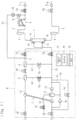
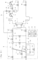
- a blood purification apparatus is applied to a hemodialysis apparatus and basically includes, as illustrated in Fig. 1 , a blood circuit in which an arterial blood circuit 2 and a venous blood circuit 3 are connected to a dialyzer 1, which serves as a blood purification unit; a dialysis device B including a duplex pump 7, an ultrafiltration pump 10, a dialysate introduction line L1, and a drain-liquid discharge line L2; a substitution line La provided with an infusion portion 16; a control unit 17; a display 18; and a calculation unit 19.
- the dialyzer 1 has thereinside blood purification membranes, which are not illustrated (while the present embodiment employs hollow-fiber hemodialysis membranes or hemodiafiltration membranes, flat hemodialysis membranes may be employed).
- the dialyzer 1 further has a blood inlet 1a, through which blood is introduced thereinto; a blood outlet 1b, through which the blood introduced thereinto is discharged therefrom; a dialysate inlet 1c, through which dialysate is introduced thereinto; and a dialysate outlet 1d, through which the dialysate introduced thereinto is discharged therefrom.
- the blood introduced into the dialyzer 1 through the blood inlet 1a comes into contact with the dialysate through the hollow fiber membranes, thereby being purified.
- the arterial blood circuit 2 basically includes a flexible tube. One end of the arterial blood circuit 2 is connected to the blood inlet 1a of the dialyzer 1, whereby the blood collected from a blood vessel of the patient is introduced into the hollow fiber membranes provided in the dialyzer 1. The other end of the arterial blood circuit 2 is provided with a connector a, to which an arterial puncture needle c is attachable. The arterial blood circuit 2 is further provided at halfway positions thereof with an arterial air-trap chamber 5 for bubble removal and a blood pump 4.
- the blood pump 4 is a peristaltic pump provided to the arterial blood circuit 2.
- the blood pump 4 squeezes the flexible tube to cause the patient's blood to flow from the side of the arterial puncture needle c toward the blood inlet 1a of the dialyzer 1.
- the blood pump 4 With the activation of the blood pump 4, the patient's blood is caused to extracorporeally circulate from the distal end of the arterial blood circuit 2 to the distal end of the venous blood circuit 3.
- the venous blood circuit 3 basically includes a flexible tube. One end of the venous blood circuit 3 is connected to the blood outlet 1b of the dialyzer 1, whereby the blood having flowed through the hollow fiber membranes is discharged from the dialyzer 1.
- the other end of the venous blood circuit 3 is provided with a connector b, to which a venous puncture needle d is attachable.
- the venous blood circuit 3 is further provided at a halfway position thereof with a venous air-trap chamber 6 for bubble removal. The patient's blood collected through the arterial puncture needle c flows through the arterial blood circuit 2 and reaches the dialyzer 1, where the blood is purified.
- the blood flows through the venous blood circuit 3 and returns into the patient's body through the venous puncture needle d.
- the extracorporeal circulation of the blood is achieved.
- the side on which the puncture needle for blood removal (blood collection) is provided is referred to as the "arterial” side
- the side on which the puncture needle for blood return is provided is referred to as the "venous” side.
- the "arterial” side and the "venous" side are not defined in accordance with which of the artery and the vein is to be the object of puncture.
- the arterial blood circuit 2 is further provided with a clamp unit Va (an arterial-blood-circuit opening-closing unit) at a position near the distal end thereof (a position between the connector a and the blood pump 4 and near the connector a).
- the clamp unit Va is capable of opening or closing the flow route.
- the venous blood circuit 3 is further provided with a clamp unit Vb at a position near the distal end thereof (a position between the connector b and the venous air-trap chamber 6 and near the connector b).
- the clamp unit Vb is capable of opening or closing the flow route.
- the clamp unit Va is provided near a distal part of the arterial blood circuit 2 and serves as an "arterial-blood-circuit opening-closing unit", which is capable of arbitrarily opening or closing the liquid flow route.
- the dialysate inlet 1c and the dialysate outlet 1d of the dialyzer 1 receive an end of the dialysate introduction line L1 and an end of the drain-liquid discharge line L2 connected thereto, respectively.
- the dialysate introduced into the dialyzer 1 through the dialysate introduction line L1 flows through spaces outside the hollow fiber membranes and is discharged as drain liquid into the drain-liquid discharge line L2.
- the spaces inside the hollow fiber membranes (purification membranes) provided in the dialyzer 1 serve as blood flow routes through which the blood is allowed to flow.
- the spaces outside the hollow fiber membranes serve as dialysate flow routes through which the dialysate is allowed to flow.
- the dialysis device B which includes the dialysate introduction line L1 and the drain-liquid discharge line L2, further includes the duplex pump 7, bypass lines L3 to L6, and electromagnetic valves V1 to V9.
- the duplex pump 7 is provided astride the dialysate introduction line L1 and the drain-liquid discharge line L2.
- the duplex pump 7 causes the dialysate, which is prepared to have a predetermined condensation in advance, to be introduced into the dialyzer 1 and also causes the dialysate used for dialysis to be discharged from the dialyzer 1.
- the duplex pump 7 includes a pump chamber on the supply side and a pump chamber on the drain side that have equal capacities, so that the volume of the dialysate to be delivered through the dialysate introduction line L1 and the volume of the drain liquid to be delivered through the drain-liquid discharge line L2 become equal.
- the duplex pump 7 may be replaced with a delivery unit of another type (not limited to a pump and may be a balance chamber) that is capable of delivering the dialysate in the dialysate introduction line L1 to the dialyzer 1.
- the dialysate introduction line L1 is provided with the electromagnetic valve V1 at a halfway position thereof (a position on the downstream side (nearer to the dialyzer 1) with respect to the joint between the dialysate introduction line L1 and the substitution line La).
- the drain-liquid discharge line L2 is provided with the electromagnetic valve V2 at a halfway position thereof (a position on the upstream side (nearer to the dialyzer 1) with respect to the joint between the drain-liquid discharge line L2 and the bypass line L3).
- the dialysate introduction line L1 is further provided with filters 8 and 9 at respective positions between the duplex pump 7 and the electromagnetic valve V1.
- the filters 8 and 9 filter and thus purify the dialysate flowing through the dialysate introduction line L1 and are connected to the bypass lines L3 and L4, respectively.
- the bypass lines L3 and L4 each serve as a bypass to the drain-liquid discharge line L2 so as to introduce the dialysate into the drain-liquid discharge line L2.
- the bypass lines L3 and L4 are provided with the electromagnetic valves V3 and V4, respectively.
- the electromagnetic valve V3 or the electromagnetic valve V4 is opened to open the corresponding flow route, the dialysate in the dialysate introduction line L1 is allowed to bypass the dialyzer 1 and flow into the drain-liquid discharge line L2.
- the dialysate introduction line L1 is further provided with the electromagnetic valve V6 at a position between the filter 8 and the filter 9.
- the drain-liquid discharge line L2 is provided with the bypass lines L5 and L6.
- the bypass lines L5 and L6 each bypass the drain side of the duplex pump 7.
- the bypass line L5 is provided with the ultrafiltration pump 10, which is provided for removing water from the patient's blood flowing through the dialyzer 1.
- the bypass line L6 is provided with the electromagnetic valve V5, which is capable of opening or closing the flow route.
- the drain-liquid discharge line L2 is further provided with a pressurizing pump 14 at a position on the upstream side with respect to the duplex pump 7 (between a joint to the bypass line L5 and the duplex pump 7).
- the pressurizing pump 14 adjusts the fluid pressure on the drain side of the duplex pump 7.
- the drain-liquid discharge line L2 is further provided with a degassing chamber 15 at a position on the upstream side with respect to the duplex pump 7 (between the pressurizing pump 14 and the duplex pump 7).
- the degassing chamber 15 is provided with an atmosphere release line L7 connected thereto through, for example, a check valve.
- the atmosphere release line L7 is provided with the electromagnetic valve V7.
- the substitution line La is connected to the arterial blood circuit 2 at a position between the distal part and the blood pump 4, whereby a substitution fluid is allowed to be introduced into the arterial blood circuit 2. More specifically, one end of the substitution line La according to the present embodiment is connected to a collecting port 11 (a so-called sampling port), which is provided to the dialysate introduction line L1. The other end of the substitution line La is connected to the arterial blood circuit 2.
- the substitution line La serves as a flow route through which the dialysate in the dialysate introduction line L1 is allowed to be supplied to the arterial blood circuit 2.
- the substitution line La is provided with a clamp unit Vc, which is capable of opening or closing the flow route.
- the dialysate is supplied to the blood circuit through the dialysate introduction line L1, whereby priming to be performed before the treatment, substitution (emergency fluid infusion) to be performed during the treatment, or blood return to be performed after the treatment is enabled.
- the clamp unit Vc is provided near the connection between the substitution line La and the arterial blood circuit 2 and serves as a "substitution-line opening-closing unit", which is capable of arbitrarily opening or closing the liquid flow route.
- the substitution line La is further provided with a rubber button 16 (an infusion portion) at a position between the collecting port 11 and the clamp unit Vc.
- the rubber button 16 allows a predetermined liquid drug (such as EPO (erythropoietin) (an erythropoiesis stimulating agent)) that should be administered to the patient to be infused into the substitution line La.
- EPO erythropoietin
- the rubber button 16 may be replaced with an infusion portion of another type that allows the infusion of the predetermined liquid drug.
- the control unit 17 is, for example, a microcomputer provided in the dialysis device B and controls at least the following: operations of opening or closing the actuators such as the blood pump 4 and the duplex pump 7, the electromagnetic valves V1 to V9, and the clamp units (Va to Vd) (particularly the clamp unit Va serving as the arterial-blood-circuit opening-closing unit and the clamp unit Vc serving as the substitution-line opening-closing unit).
- the control unit 17 is electrically connected to sensors such as fluid-pressure measurement sensors, a venous-pressure sensor, bubble detection sensors, condensation sensors, temperature sensors (all not illustrated) so as to be able to execute predetermined control sequences.
- substitution to be performed during the treatment and blood return to be performed after the treatment are achievable by supplying the dialysate in the dialysate introduction line L1 to the blood circuit.
- Emergency fluid infusion is a step of supplying the dialysate, serving as an emergency fluid, to the blood circuit if, for example, the blood pressure of the patient drops excessively during the treatment.
- Blood return is a step of returning the blood remaining in the blood circuit to the patient by supplying the dialysate, serving as the substitution fluid, to the blood circuit after the treatment.
- the control unit 17 executes a drug introduction mode, which includes a negative-pressure-generating step (a pressure-controlling step) of generating a negative pressure in a portion of the arterial blood circuit 2 that is between the distal part and the blood pump 4 by closing the clamp unit Vc (the substitution-line opening-closing unit) and the clamp unit Va (the arterial-blood-circuit opening-closing unit); a suction step of suctioning the substitution fluid in the substitution line La into the arterial blood circuit 2 by opening the clamp unit Vc after the negative-pressure-generating step (the pressure-controlling step); and an introduction step of introducing the substitution fluid in the substitution line La into the arterial blood circuit 2 by activating the blood pump 4 after the suction step.
- the liquid drug infused from the rubber button 16 (the infusion portion) is suctioned or introduced into the arterial blood circuit 2 together with the substitution fluid.
- the display 18 is a touch panel attached to the dialysis device B and is capable of displaying the following, as illustrated in Fig. 2 : a target-ultrafiltration-volume display portion 18a, in which a target ultrafiltration volume is displayed; a starting portion 18b, which enables an operation of starting the drug introduction mode; a substitution-volume display portion 18c, in which the volume of the substitution fluid introduced from the substitution line La into the arterial blood circuit 2 with the execution of the drug introduction mode is displayed; a number-of-executions display portion 18d, in which the number of times of execution of the drug introduction mode (that is, the number of times of infusion of the liquid drug from the rubber button 16 (the infusion portion)) is displayed; a treatment display portion 18e, in which the duration of the blood purification treatment is displayed; an actual-measurement display portion 18f, in which the ultrafiltration volume (the actual ultrafiltration volume) measured in the blood purification treatment (the treatment mode) is displayed; and a ratio display portion 18g, in which the ratio of the actual ultrafiltration volume
- the drug introduction mode is executed by the control unit 17, in which the volume of the substitution fluid introduced from the substitution line La into the arterial blood circuit 2 with the execution of the drug introduction mode is displayed in the substitution-volume display portion 18c, and the number of times of infusion of the liquid drug from the rubber button 16 in the current blood purification treatment is displayed in the number-of-executions display portion 18d.
- the calculation unit 19 calculates the volume of the substitution fluid introduced from the substitution line La into the arterial blood circuit 2 with the execution of the drug introduction mode. The volume of the substitution fluid thus calculated is displayed in the substitution-volume display portion 18c.
- the display 18 may further provide an indication Q1, illustrated in Fig. 18 , which prompts the execution of the drug introduction mode; or an indication Q2, illustrated in Fig. 19 , which prompts the infusion of the liquid drug from the rubber button 16 (the infusion portion).
- the indication Q1 is preferably provided as an image of a hand pointing the starting portion 18b (see Fig. 18 ).
- the indication provided in the treatment display portion 18e is preferably changed to the indication Q2, which is an image of a syringe and the rubber button 16 (see Fig. 19 ).
- the blood purification treatment As illustrated in Fig. 4 , when the blood pump 4 and the duplex pump 7 are activated while a patient is punctured with the arterial puncture needle c and the venous puncture needle d, the patient's blood is caused to extracorporeally circulate through the arterial blood circuit 2 and the venous blood circuit 3, whereby the blood undergoes the blood purification treatment in the dialyzer 1.
- the clamp unit Va the arterial-blood-circuit opening-closing unit
- the clamp unit Vb are open
- the clamp unit Vc the substitution-line opening-closing unit
- the electromagnetic valves V3 and V4 are closed.
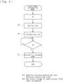
- a medical worker touches the starting portion 18b of the display 18, whereby the drug introduction mode is executed.
- the blood pump 4 is temporarily stopped.
- the electromagnetic valves V1 and V2 are closed.
- the electromagnetic valve V3 is opened, whereby the control sequence proceeds to a bypassing step S1.
- the bypassing step S1 the flow routes that allow the dialysate to be introduced into the dialyzer 1 (the blood purification unit) through the dialysate introduction line L1 and discharged from the dialyzer 1 (the blood purification unit) into the drain-liquid discharge line L2 are closed (that is, the electromagnetic valves V1 and V2 are closed), whereby the dialysate is caused to flow through the bypass line L3.
- the negative-pressure-generating step (the pressure-controlling step) S2 is executed.
- the blood pump 4 is activated with the clamp unit Vc (the substitution-line opening-closing unit) and the clamp unit Va (the arterial-blood-circuit opening-closing unit) closed, whereby a negative pressure is generated in a portion of the arterial blood circuit 2 that is between the distal part (the part closed by the clamp unit Va) and the blood pump 4.
- the clamp unit Va and the clamp unit Vc are closed, a closed circuit is established, in which the blood pump 4 is activated. Accordingly, the blood in the closed circuit is discharged toward the downstream side with respect to the blood pump 4. Consequently, a negative pressure is generated.
- the negative-pressure-generating step (the pressure-controlling step) S2 is continued until the number of revolutions of the rotor of the blood pump 4 reaches a preset value or until a predetermined period of time elapses after the start of the activation of the blood pump 4.
- the suction step S3 is executed.
- the blood pump 4 is kept active, and the clamp unit Vc (the substitution-line opening-closing unit) is opened, whereby the substitution fluid in the substitution line La is suctioned into the arterial blood circuit 2.
- the negative-pressure-generating step (the pressure-controlling step) S2 a negative pressure is generated at the connection between the arterial blood circuit 2 and the substitution line La. In such a state, when the clamp unit Vc is opened, the substitution fluid in the substitution line La is suctioned under the negative pressure into the arterial blood circuit 2.
- the suction step S3 is continued until the number of revolutions of the rotor of the blood pump 4 reaches a preset value or until a predetermined period of time elapses after the start of the suction step S3.
- the introduction step S4 is executed.
- the blood pump 4 is kept active, the clamp unit Vc (the substitution-line opening-closing unit) is kept open, and the clamp unit Va (the arterial-blood-circuit opening-closing unit) is kept closed, whereby the blood pump 4 that is active causes the substitution fluid in the substitution line La to be introduced into the arterial blood circuit 2.
- the suction step S3 ends, the negative pressure at the connection between the arterial blood circuit 2 and the substitution line La is removed. Therefore, with the blood pump 4 kept active for liquid delivery, the substitution fluid in the substitution line La is introduced into the arterial blood circuit 2.
- the liquid drug thus infused is suctioned or introduced into the arterial blood circuit 2 together with the substitution fluid in the substitution line La.
- the volume of the substitution fluid introduced into the arterial blood circuit 2 with the execution of the drug introduction mode is displayed in the substitution-volume display portion 18c, and the number of times of execution of the drug introduction mode is displayed in the number-of-executions display portion 18d.
- the timing of infusion of the liquid drug from the rubber button 16 is arbitrary but is preferably a point between the suction step S3 and the introduction step S4 inclusive.
- S5 it is determined whether or not a preset volume of the substitution fluid (the substitution fluid containing the liquid drug) has been introduced from the substitution line La into the arterial blood circuit 2 in the introduction step S4. If it is determined that the preset volume of the substitution fluid has been introduced, the sequence proceeds to S6, where the mode is changed to the treatment mode illustrated in Fig. 4 . Thus, the sequence of the drug introduction mode ends, and the mode is changed to the treatment mode to restart the blood purification treatment. In the blood purification treatment, the driving speed of the blood pump 4 before the execution of the drug introduction mode is stored. After the drug introduction mode is complete, the stored driving speed is resumed.
- the present embodiment employs the same steps S1 to S5 as those employed by the first embodiment.
- S5 it is determined whether or not a preset volume of the substitution fluid (the substitution fluid containing the liquid drug) has been introduced from the substitution line La into the arterial blood circuit 2 in the introduction step S4. If it is determined that the preset volume of the substitution fluid has been introduced, the sequence proceeds to S6, where the target ultrafiltration volume is corrected.
- a target ultrafiltration volume for water removal from the patient's blood through the dialyzer 1 is settable. Furthermore, the calculation unit 19 calculates the volume of the substitution fluid introduced from the substitution line La into the arterial blood circuit 2 with the execution of the drug introduction mode. Therefore, when the drug introduction mode is executed, the target ultrafiltration volume is corrected with the addition of the volume of the substitution fluid calculated by the calculation unit 19.
- the sequence proceeds to S7, where the mode is changed to the treatment mode illustrated in Fig. 4 .
- the sequence of the drug introduction mode ends, and the mode is changed to the treatment mode to restart the blood purification treatment.
- the driving speed of the blood pump 4 before the execution of the drug introduction mode is stored. After the drug introduction mode is complete, the stored driving speed is resumed.
- the blood purification treatment As with the case of the first embodiment and as illustrated in Fig. 4 , when the blood pump 4 and the duplex pump 7 are activated while a patient is punctured with the arterial puncture needle c and the venous puncture needle d, the patient's blood is caused to extracorporeally circulate through the arterial blood circuit 2 and the venous blood circuit 3, whereby the blood undergoes the blood purification treatment in the dialyzer 1.
- the clamp unit Va the arterial-blood-circuit opening-closing unit
- the clamp unit Vb are open
- the clamp unit Vc the substitution-line opening-closing unit
- the electromagnetic valves V3 and V4 are closed.
- a medical worker touches the starting portion 18b of the display 18, whereby the drug introduction mode is executed.
- the blood pump 4 is temporarily stopped (see Fig. 5 ). Then, as illustrated in Fig. 10 , the clamp unit Va (the arterial-blood-circuit opening-closing unit) and the clamp unit Vc (the substitution-line opening-closing unit) are closed.
- the electromagnetic valves V3 and V4 are closed, the electromagnetic valves V1 and V2 are open, and the duplex pump 7 is active. Therefore, the dialysate is introduced into the dialyzer 1 through the dialysate introduction line L1, and the resulting drain liquid is discharged from the dialyzer 1 into the drain-liquid discharge line L2. Furthermore, since the duplex pump 7 is active, the volume of the dialysate delivered through the dialysate introduction line L1 and the volume of the drain liquid delivered through the drain-liquid discharge line L2 are equal. Subsequently, the blood pump 4 is activated, whereby the negative-pressure-generating step (the pressure-controlling step) S1 is executed.
- the blood pump 4 is activated with the clamp unit Vc (the substitution-line opening-closing unit) and the clamp unit Va (the arterial-blood-circuit opening-closing unit) closed, whereby a negative pressure is generated in a portion of the arterial blood circuit 2 that is between the distal part (the part closed by the clamp unit Va) and the blood pump 4.
- the clamp unit Va and the clamp unit Vc are closed, a closed circuit is established, in which the blood pump 4 is activated. Accordingly, the blood in the closed circuit is discharged toward the downstream side with respect to the blood pump 4. Consequently, a negative pressure is generated.
- the negative-pressure-generating step (the pressure-controlling step) S1 is continued until the number of revolutions of the rotor of the blood pump 4 reaches a preset value or until a predetermined period of time elapses after the start of the activation of the blood pump 4.
- the suction step S2 is executed.
- the blood pump 4 is kept active, and the clamp unit Vc (the substitution-line opening-closing unit) is opened, whereby the substitution fluid in the substitution line La is suctioned into the arterial blood circuit 2.
- the negative-pressure-generating step (the pressure-controlling step) S1 a negative pressure is generated at the connection between the arterial blood circuit 2 and the substitution line La. In such a state, when the clamp unit Vc is opened, the substitution fluid in the substitution line La is suctioned under the negative pressure into the arterial blood circuit 2.
- the suction step S2 is continued until the number of revolutions of the rotor of the blood pump 4 reaches a preset value or until a predetermined period of time elapses after the start of the suction step S2.
- the introduction step S3 is executed.
- the blood pump 4 is kept active, the clamp unit Vc (the substitution-line opening-closing unit) is kept open, and the clamp unit Va (the arterial-blood-circuit opening-closing unit) is kept closed, whereby the blood pump 4 that is active causes the substitution fluid in the substitution line La to be introduced into the arterial blood circuit 2.
- the suction step S2 ends, the negative pressure at the connection between the arterial blood circuit 2 and the substitution line La is removed. Therefore, with the blood pump 4 kept active for liquid delivery, the substitution fluid in the substitution line La is introduced into the arterial blood circuit 2.
- the liquid drug thus infused is suctioned or introduced into the arterial blood circuit 2 together with the substitution fluid in the substitution line La.
- the volume of the substitution fluid introduced into the arterial blood circuit 2 with the execution of the drug introduction mode is displayed in the substitution-volume display portion 18c, and the number of times of execution of the drug introduction mode is displayed in the number-of-executions display portion 18d.
- the volume of the dialysate delivered through the dialysate introduction line L1 and the volume of the drain liquid delivered through the drain-liquid discharge line L2 are equal. Therefore, when the drug introduction mode is executed, a volume of water that corresponds to the volume of the substitution fluid introduced into the arterial blood circuit 2 in the suction step S2 or the introduction step S3 is removed through the dialyzer 1.
- the volume of the dialysate introduced into the dialyzer 1 becomes smaller than the volume of the drain liquid by the volume of the dialysate flowing into the substitution line La. Consequently, a volume of water corresponding to the reduction is discharged from the dialyzer 1 into the drain-liquid discharge line L2. Therefore, when the drug introduction mode is executed, the volume of water that corresponds to the volume of the substitution fluid introduced into the arterial blood circuit 2 in the suction step S2 or the introduction step S3 is naturally removed through the dialyzer 1.
- S4 it is determined whether or not a preset volume of the substitution fluid (the substitution fluid containing the liquid drug) has been introduced from the substitution line La into the arterial blood circuit 2 in the introduction step S3. If it is determined that the preset volume of the substitution fluid has been introduced, the sequence proceeds to S5, where the mode is changed to the treatment mode illustrated in Fig. 4 . Thus, the sequence of the drug introduction mode ends, and the mode is changed to the treatment mode to restart the blood purification treatment. In the blood purification treatment, the driving speed of the blood pump 4 before the execution of the drug introduction mode is stored. After the drug introduction mode is complete, the stored driving speed is resumed.
- the blood purification treatment As illustrated in Fig. 13 , when the blood pump 4 and the duplex pump 7 are activated while a patient is punctured with the arterial puncture needle c and the venous puncture needle d, the patient's blood is caused to extracorporeally circulate through the arterial blood circuit 2 and the venous blood circuit 3, whereby the blood undergoes the blood purification treatment in the dialyzer 1.
- the clamp unit Va the arterial-blood-circuit opening-closing unit
- the clamp unit Vb are open
- the clamp unit Vc the substitution-line opening-closing unit
- the electromagnetic valves V3 and V4 are closed.
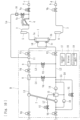
- the blood purification apparatus includes a substitution line Lb branching off from a halfway position of the substitution line La and connected to a position of the venous blood circuit 3 that is between the dialyzer 1 and the venous air-trap chamber 6.
- the apparatus further includes a substitution pump 20 provided to the substitution line Lb.
- the substitution pump 20 When the substitution pump 20 is activated, the dialysate serving as the substitution fluid is introduced from the dialysate introduction line L1 into the venous blood circuit 3.
- the substitution pump 20 is a peristaltic pump. When the substitution pump 20 is activated, the substitution pump 20 squeezes the flexible tube to deliver the substitution fluid. When the substitution pump 20 is stopped, the flow route of the flexible tube is closed.
- the substitution line Lb is provided with the rubber button 16, serving as the infusion portion, at a position on the upstream side with respect to the substitution pump 20 (between the substitution pump 20 and the collecting port 11).
- the rubber button 16 allows a predetermined liquid drug that should be administered to the patient to be infused into the substitution line Lb.
- the distal end of the substitution line Lb is connected to the position of the venous blood circuit 3 that is between the dialyzer 1 and the venous air-trap chamber 6.
- the distal end of the substitution line Lb may be connected to any other position, such as another position of the venous blood circuit 3 or a predetermined position of the arterial blood circuit 2, as long as the position is defined in the blood circuit and on the downstream side with respect to the blood pump 4.
- a medical worker touches the starting portion 18b of the display 18, whereby the drug introduction mode is executed.
- the blood pump 4 is temporarily stopped (see Fig. 5 ).
- the electromagnetic valves V1 and V2 are closed.
- the electromagnetic valve V3 is opened, whereby the control sequence proceeds to the bypassing step S1.
- the flow routes that allow the dialysate to be introduced into the dialyzer 1 (the blood purification unit) through the dialysate introduction line L1 and discharged from the dialyzer 1 (the blood purification unit) into the drain-liquid discharge line L2 are closed (that is, the electromagnetic valves V1 and V2 are closed), whereby the dialysate is caused to flow through the bypass line L3.
- the introduction step S2 is executed.
- the blood pump 4 is kept active, and the substitution pump 20 is activated, whereby the substitution fluid in the substitution line Lb is introduced into the blood circuit (in the present embodiment, the venous blood circuit 3), and the liquid drug infused from the rubber button 16 (the infusion portion) is thus introduced into the blood circuit together with the substitution fluid.
- the substitution pump 20 is activated, the flow route of the substitution line Lb is closed. However, with the activation of the substitution pump 20, the substitution fluid in the substitution line Lb is caused to flow into the blood circuit.
- the substitution pump 20 Before the execution of the introduction step S2, it is preferable to generate a positive pressure in a portion of the substitution line Lb that is on the upstream side with respect to the substitution pump 20 by activating the duplex pump 7. In such a case, the liquid drug infused to the portion on the upstream side with respect to the substitution pump 20 is retained near the substitution pump 20. Therefore, when the substitution pump 20 is activated, the liquid drug is delivered to the blood circuit (in the present embodiment, the venous blood circuit 3) without flowing backward to the dialysate introduction line L1.
- such a positive pressure generated in the portion of the substitution line Lb that is on the upstream side with respect to the substitution pump 20 also prevents the occurrence of backflow of the blood in the blood circuit (in the present embodiment, the venous blood circuit 3) through a gap in the substitution pump 20 (a gap that may be produced if the flexible tube is not fully closed by the rollers).
- the liquid drug thus infused is introduced into the blood circuit (the venous blood circuit 3) together with the substitution fluid in the substitution line Lb.
- the volume of the substitution fluid introduced into the venous blood circuit 3 with the execution of the drug introduction mode is displayed in the substitution-volume display portion 18c, and the number of times of execution of the drug introduction mode is displayed in the number-of-executions display portion 18d.
- the sequence proceeds to S4, where the target ultrafiltration volume is corrected.
- a target ultrafiltration volume for water removal from the patient's blood through the dialyzer 1 is settable.
- the calculation unit 19 calculates the volume of the substitution fluid introduced from the substitution line Lb into the venous blood circuit 3 (any position of the blood circuit that is on the downstream side with respect to the blood pump 4) with the execution of the drug introduction mode. Therefore, when the drug introduction mode is executed, the target ultrafiltration volume is corrected with the addition of the volume of the substitution fluid calculated by the calculation unit 19.
- the sequence proceeds to S5, where the mode is changed to the treatment mode illustrated in Fig. 13 .
- the sequence of the drug introduction mode ends, and the mode is changed to the treatment mode to restart the blood purification treatment.
- the driving speed of the blood pump 4 is controlled to be higher than the driving speed in the drug introduction mode.
- the present embodiment employs the substitution pump 20 and the substitution line Lb, which are the same as those employed by the fourth embodiment.
- the blood purification treatment as with the case of the fourth embodiment and as illustrated in Fig. 13 , when the blood pump 4 and the duplex pump 7 are activated while a patient is punctured with the arterial puncture needle c and the venous puncture needle d, the patient's blood is caused to extracorporeally circulate through the arterial blood circuit 2 and the venous blood circuit 3, whereby the blood undergoes the blood purification treatment in the dialyzer 1.
- the clamp unit Va the arterial-blood-circuit opening-closing unit
- the clamp unit Vb are open
- the clamp unit Vc the substitution-line opening-closing unit
- the electromagnetic valves V3 and V4 are closed.
- a medical worker touches the starting portion 18b of the display 18, whereby the drug introduction mode is executed.
- the substitution pump 20 is activated, whereby the introduction step S1 is executed.
- the electromagnetic valves V3 and V4 are closed, the electromagnetic valves V1 and V2 are open, and the duplex pump 7 is active. Therefore, the dialysate is introduced into the dialyzer 1 through the dialysate introduction line L1, and the resulting drain liquid is discharged from the dialyzer 1 into the drain-liquid discharge line L2.
- the duplex pump 7 since the duplex pump 7 is active, the volume of the dialysate delivered through the dialysate introduction line L1 and the volume of the drain liquid delivered through the drain-liquid discharge line L2 are equal.
- the blood pump 4 is kept active, and the substitution pump 20 is activated, whereby the substitution fluid in the substitution line Lb is introduced into the blood circuit (in the present embodiment, the venous blood circuit 3), and the liquid drug infused from the rubber button 16 (the infusion portion) is thus introduced into the blood circuit together with the substitution fluid.
- the substitution pump 20 is activated, the flow route of the substitution line Lb is closed. However, with the activation of the substitution pump 20, the substitution fluid in the substitution line Lb is caused to flow into the blood circuit.
- the substitution pump 20 Before the execution of the introduction step S1, it is preferable to generate a positive pressure in a portion of the substitution line Lb that is on the upstream side with respect to the substitution pump 20 by activating the duplex pump 7. In such a case, the liquid drug infused to the portion on the upstream side with respect to the substitution pump 20 is retained near the substitution pump 20. Therefore, when the substitution pump 20 is activated, the liquid drug is delivered to the blood circuit (in the present embodiment, the venous blood circuit 3) without flowing backward to the dialysate introduction line L1.
- such a positive pressure generated in the portion of the substitution line Lb that is on the upstream side with respect to the substitution pump 20 also prevents the occurrence of backflow of the blood in the blood circuit (in the present embodiment, the venous blood circuit 3) through a gap in the substitution pump 20 (a gap that may be produced if the flexible tube is not fully closed by the rollers).
- the liquid drug thus infused is introduced into the blood circuit (the venous blood circuit 3) together with the substitution fluid in the substitution line Lb.
- the volume of the substitution fluid introduced into the venous blood circuit 3 with the execution of the drug introduction mode is displayed in the substitution-volume display portion 18c, and the number of times of execution of the drug introduction mode is displayed in the number-of-executions display portion 18d.
- the volume of the dialysate delivered through the dialysate introduction line L1 and the volume of the drain liquid delivered through the drain-liquid discharge line L2 are equal. Therefore, when the drug introduction mode is executed, a volume of water that corresponds to the volume of the substitution fluid introduced into the venous blood circuit 3 in the introduction step S1 is removed through the dialyzer 1.
- the substitution pump 20 when the substitution pump 20 is activated, some of the dialysate in the dialysate introduction line L1 flows into the substitution line Lb and reaches the venous blood circuit 3. Therefore, the volume of the dialysate introduced into the dialyzer 1 becomes smaller than the volume of the drain liquid by the volume of the dialysate flowing into the substitution line Lb. Consequently, a volume of water corresponding to the reduction is discharged from the dialyzer 1 into the drain-liquid discharge line L2. Therefore, when the drug introduction mode is executed, the volume of water that corresponds to the volume of the substitution fluid introduced into the venous blood circuit 3 in the introduction step S1 is naturally removed through the dialyzer 1.
- the sequence proceeds to S3, where the mode is changed to the treatment mode illustrated in Fig. 13 .
- the sequence of the drug introduction mode ends, and the mode is changed to the treatment mode to restart the blood purification treatment.
- the driving speed of the blood pump 4 is controlled to be higher than the driving speed in the drug introduction mode.
- the blood purification apparatus includes the control unit that executes the drug introduction mode in which the substitution fluid in the substitution line (La, Lb) is introduced into the blood circuit, the control unit causing the liquid drug infused from the rubber button 16 (the infusion portion) in the drug introduction mode to be introduced into the blood circuit together with the substitution fluid; and the calculation unit that calculates the volume of the substitution fluid introduced from the substitution line (La, Lb) into the blood circuit with the execution of the drug introduction mode. Therefore, when a liquid drug is infused from the substitution line (La, Lb) into the blood circuit, the blood flowing in the blood circuit is prevented from flowing into the substitution line (La, Lb). Furthermore, medical workers are made aware of an appropriate timing of liquid drug infusion.
- the blood purification apparatus includes the calculation unit 19 that calculates the volume of the substitution fluid introduced from the substitution line (La, Lb) into the blood circuit with the execution of the drug introduction mode, the volume of water that corresponds to the volume of the substitution fluid introduced into the patient's body with the execution of the drug introduction mode is identifiable for the ultrafiltration in the blood purification treatment.
- the drug introduction mode is executed, which includes the negative-pressure-generating step (the pressure-controlling step) of generating a negative pressure in the portion of the arterial blood circuit 2 that is between the distal part and the blood pump 4 by closing the clamp unit Vc (the substitution-line opening-closing unit) and the clamp unit Va (the arterial-blood-circuit opening-closing unit); the suction step of suctioning the substitution fluid in the substitution line La into the arterial blood circuit 2 by opening the clamp unit Va after the negative-pressure-generating step (the pressure-controlling step); and the introduction step of introducing the substitution fluid in the substitution line La into the arterial blood circuit 2 by activating the blood pump 4 after the suction step.
- the negative-pressure-generating step the pressure-controlling step
- the liquid drug infused from the rubber button 16 (the infusion portion) is suctioned or introduced into the arterial blood circuit 2 together with the substitution fluid in the suction step or the introduction step. Therefore, with the negative pressure generated when the liquid drug is infused from the substitution line La into the blood circuit, the blood flowing in the blood circuit is more assuredly prevented from flowing into the substitution line La.
- the control unit 17 executes the drug introduction mode if the predetermined starting operation is performed. Therefore, the liquid drug is infusible into the infusion portion with an arbitrary timing.
- the control unit 17 causes the substitution fluid in the substitution line La to be introduced into the arterial blood circuit 2 by activating the blood pump 4 in the suction step for the generation of the negative pressure and by keeping the blood pump 4 active in the introduction step. Therefore, with the activation of the blood pump 4, the generation of the negative pressure in the negative-pressure-generating step (the pressure-controlling step) and the introduction of the substitution fluid in the introduction step are achieved successively.
- the target ultrafiltration volume for water removal from the blood of the patient through the dialyzer 1 is settable. Furthermore, when the drug introduction mode is executed, the target ultrafiltration volume is corrected with the addition of the volume of the substitution fluid calculated by the calculation unit 19. Therefore, the volume of water that corresponds to the volume of the substitution fluid introduced into the patient's body with the execution of the drug introduction mode is automatically removed in the blood purification treatment.
- the substitution line (La, Lb) is connected to the dialysate introduction line L1 and to the blood circuit in such a manner as to allow the dialysate in the dialysate introduction line L1 to be introduced as the substitution fluid into the blood circuit.
- the control unit 17 executes the bypassing step in which the control unit 17 causes the dialysate to flow through the bypass line L3 by closing the flow routes that allow the dialysate to be introduced into the dialyzer 1 through the dialysate introduction line L1 and discharged from the dialyzer 1 into the drain-liquid discharge line L2. Therefore, the liquid drug is prevented from being discharged from the dialyzer 1 into the drain-liquid discharge line L2.
- the substitution line (La, Lb) is connected to the dialysate introduction line L1 and to the blood circuit in such a manner as to allow the dialysate in the dialysate introduction line L1 to be introduced as the substitution fluid into the blood circuit. Furthermore, when the drug introduction mode is executed, the control unit 17 causes a volume of water that corresponds to the volume of the substitution fluid introduced into the blood circuit in the suction step or the introduction step to be removed through the dialyzer 1. Therefore, the volume of water that corresponds to the volume of the substitution fluid suctioned or introduced into the blood circuit with the execution of the drug introduction mode is removed through the dialyzer 1.
- the blood purification apparatus includes the duplex pump 7 provided astride the dialysate introduction line L1 and the drain-liquid discharge line L2 and that delivers the dialysate in the dialysate introduction line L1 to the drain-liquid discharge line L2, the duplex pump 7 equalizing the volume of the dialysate to be delivered through the dialysate introduction line L1 and the volume of the drain liquid to be delivered through the drain-liquid discharge line L2. Therefore, when the duplex pump 7 is activated, the volume of water that corresponds to the volume of the substitution fluid suctioned or introduced into the blood circuit with the execution of the drug introduction mode is naturally removed through the dialyzer 1.
- the blood purification apparatus is configured to display an indication that prompts the execution of the drug introduction mode or an indication that prompts the infusion of the liquid drug from the rubber button 16 (the infusion portion), medical workers are prevented from forgetting to start the drug introduction mode or to infuse the liquid drug from the rubber button 16. Furthermore, when the drug introduction mode is executed, the volume of the substitution fluid introduced from the substitution line (La, Lb) into the blood circuit or the number of times of infusion of the liquid drug from the rubber button 16 (the infusion portion) is displayed. Therefore, medical workers are correctly made aware of the volume of the substitution fluid or the number of times of infusion of the liquid drug.
- the blood purification apparatus includes the substitution pump 20 provided to the substitution line Lb and that delivers the substitution fluid to the blood circuit. Furthermore, the control unit 17 executes the drug introduction mode by executing the introduction step of introducing the substitution fluid in the substitution line Lb into the blood circuit by activating the substitution pump 20. Furthermore, the liquid drug infused from the rubber button 16 (the infusion portion) is introduced into the blood circuit together with the substitution fluid in the introduction step. Therefore, when the liquid drug is infused from the substitution line Lb into the blood circuit, the activation of the substitution pump 20 prevents the blood in the blood circuit from flowing into the substitution line Lb. Furthermore, medical workers are made aware of an appropriate timing of liquid drug infusion.
- the timing of liquid drug infusion from the rubber button 16 is not limited to a point in the suction step or the introduction step (that is, after the clamp unit Vc (the substitution-line opening-closing unit) is opened in the suction step) as in the above embodiments.
- the liquid drug may be infused from the rubber button 16 before the suction step.
- the above substitution line La may be replaced with a substitution line La', which is connected to a bag containing physiological saline serving as the substitution fluid and allows the physiological saline as the substitution fluid to be introduced into the arterial blood circuit 2 by opening the clamp unit Vc (the substitution-line opening-closing unit).
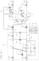
- the blood purification apparatus may include an air-trap chamber D provided at the connection between the arterial blood circuit 2 and the substitution line La, and a liquid-level-adjusting pump M that adjusts the surface level of a liquid layer in the air-trap chamber D by introducing or discharging air into or from an air layer in the air-trap chamber D.
- the control unit 17 may activate the liquid-level-adjusting pump M together with or instead of the blood pump 4 in the suction step.
- the negative pressure to be generated in the negative-pressure-generating step may be generated by utilizing the liquid-level-adjusting pump M, which is intended for the adjustment of the liquid level in the air-trap chamber D.
- reference signs Vd and S respectively denotes a clamp unit provided to a flow route for the introduction or discharge of air into or from the air-trap chamber D, and a pressure-measurement unit for measuring the pressure in the flow route.
- a volume of water that corresponds to the volume of the substitution fluid calculated by the calculation unit 19 be removed from the blood of the patient through the dialyzer 1 (the blood purification unit).
- the ultrafiltration by the dialyzer 1 may be executed either in the drug introduction mode or in the treatment mode. In either mode, the volume of water corresponding to the volume of the substitution fluid introduced into the patient's body together with the liquid drug is removed assuredly.
- the negative-pressure-generating step (the pressure-controlling step) is not limited to a step of generating a negative pressure and only needs to be a step of controlling, when the drug introduction mode is executed, the pressure at the connection between the blood circuit (the arterial blood circuit 2 or the venous blood circuit 3) and the substitution line (La or Lb) to be equal to or lower than the fluid pressure in the substitution line (La or Lb).
- the fluid pressure may be controlled with reference to the atmospheric pressure (0 kPa) by closing the clamp unit Va (the arterial-blood-circuit opening-closing unit) and the clamp unit Vc (the substitution-line opening-closing unit) to establish a closed system and then rotating the blood pump 4 normally or reversely.
- the pressure is controllable by controlling the driving speed of the duplex pump 7.
- the pressure at the connection between the blood circuit and the substitution line Lb is controlled by the control unit 17 at the execution of the drug introduction mode, the occurrence of backflow of the blood into the substitution line Lb is avoided.
- the present invention is also applicable to a blood purification apparatus having additional functions, as long as the apparatus includes a control unit that executes a drug introduction mode in which a substitution fluid in a substitution line is introduced into a blood circuit, the control unit causing a liquid drug infused from an infusion portion in the drug introduction mode to be introduced into the blood circuit together with the substitution fluid; and a calculation unit that calculates a volume of the substitution fluid introduced from the substitution line into the blood circuit with the execution of the drug introduction mode.
Landscapes
- Health & Medical Sciences (AREA)
- Heart & Thoracic Surgery (AREA)
- Vascular Medicine (AREA)
- Animal Behavior & Ethology (AREA)
- Anesthesiology (AREA)
- Biomedical Technology (AREA)
- Hematology (AREA)
- Life Sciences & Earth Sciences (AREA)
- Engineering & Computer Science (AREA)
- General Health & Medical Sciences (AREA)
- Public Health (AREA)
- Veterinary Medicine (AREA)
- Urology & Nephrology (AREA)
- Cardiology (AREA)
- Emergency Medicine (AREA)
- External Artificial Organs (AREA)
Claims (14)
- Ein Blutreinigungsapparat, der folgendes beinhalteteinen Blutkreislauf, der einen arteriellen Blutkreislauf (2) und einen venösen Blutkreislauf (3) beinhaltet und durch den das Blut eines Patienten extrakorporal zirkulieren kann;eine Blutreinigungseinheit, die mit dem arteriellen Blutkreislauf (2) und dem venösen Blutkreislauf (3) verbunden und zwischen diesen vorgesehen ist und die das durch den Blutkreislauf fließende Blut reinigt;eine Blutpumpe (4), die mit dem arteriellen Blutkreislauf (2) verbunden ist und das Blut des Patienten von einem distalen Ende des arteriellen Blutkreislaufs (2) zu einem distalen Ende des venösen Blutkreislaufs (3) befördert;eine Substitutionsleitung (La, Lb), durch die ein Substitutionsfluid in den Blutkreislauf eingeführt werden kann; undeinen Infusionsabschnitt, der an der Substitutionsleitung (La, Lb) angebracht ist und aus dem ein vorbestimmtes flüssiges Medikament, das dem Patienten verabreicht werden soll, in die Substitutionsleitung (La, Lb) infundiert werden kann,dadurch gekennzeichnet, dass der Blutreinigungsapparat ferner umfassteine Steuereinheit (17), die einen Medikamenteneinführungsmodus ausführt, in dem das Substitutionsfluid in der Substitutionsleitung (La, Lb) in den Blutkreislauf eingeführt wird, wobei die Steuereinheit (17) bewirkt, dass das flüssige Medikament, das im Medikamenteneinführungsmodus aus dem Infusionsabschnitt infundiert wird, zusammen mit dem Substitutionsfluid in den Blutkreislauf eingeführt wird; undeine Berechnungseinheit (19), die ein Volumen des Substitutionsfluids, das von der Substitutionsleitung (La, Lb) in den Blutkreislauf eingeführt wird, bei der Ausführung des Medikamenteneinführungsmodus berechnet.
- Der Blutreinigungsapparat nach Anspruch 1, wobei ein Wasservolumen, das dem von der Berechnungseinheit (19) berechneten Volumen des Substitutionsfluids entspricht, durch die Blutreinigungseinheit aus dem Blut des Patienten entfernt wird.
- Der Blutreinigungsapparat nach Anspruch 1 oder 2, wobei die Steuerung (17) bei Ausführung des Medikamenteneinführungsmodus einen Druck an einer Verbindung zwischen dem Blutkreislauf und der Substitutionsleitung (La, Lb) so steuert, dass er gleich oder niedriger ist als ein Fluiddruck in der Substitutionsleitung (La, Lb).
- Der Blutreinigungsapparat nach einem der Ansprüche 1 bis 3, der ferner umfasst:eine Öffnungs-Schließ-Einheit für den arteriellen Blutkreislauf, die in der Nähe eines distalen Teils des arteriellen Blutkreislaufs (2) vorgesehen ist und die in der Lage ist, einen Strömungsweg für Flüssigkeiten beliebig zu öffnen oder zu schließen; undeine Öffnungs-Schließ-Einheit für die Substitutionsleitung, die in der Nähe einer Verbindung zwischen der Substitutionsleitung (La, Lb) und dem arteriellen Blutkreislauf (2) vorgesehen ist und die in der Lage ist, einen Strömungsweg für die Flüssigkeit wahlweise zu öffnen oder zu schließen,wobei die Steuereinheit (17) den Medikamenteneinführungsmodus ausführt durch Ausführen von einen Unterdruck-Erzeugungsschritt zum Erzeugen eines Unterdrucks in einem Abschnitt des arteriellen Blutkreislaufs (2), der sich zwischen dem distalen Teil und der Blutpumpe (4) befindet, durch Schließen der Öffnungs-Schließ-Einheit der Substitutionsleitung und der Öffnungs-Schließ-Einheit des arteriellen Blutkreislaufs;einen Ansaugschritt des Ansaugens des Substitutionsfluids in der Substitutionsleitung (La, Lb) in den arteriellen Blutkreislauf (2) durch Öffnen der Öffnungs-Schließ-Einheit der Substitutionsleitung nach dem Unterdruck-Erzeugungsschritt; undeinen Einführungsschritt des Einführens des Substitutionsfluids in die Substitutionsleitung (La, Lb) in den arteriellen Blutkreislauf (2) durch Aktivieren der Blutpumpe (4) nach dem Ansaugschritt, undwobei das flüssige Medikament, das aus dem Infusionsabschnitt infundiert wird, zusammen mit dem Substitutionsfluid in dem Ansaugschritt oder dem Einführungsschritt in den Blutkreislauf gesaugt oder eingeführt wird.
- Der Blutreinigungsapparat nach einem der Ansprüche 1 bis 4, wobei die Steuerung (17) den Medikamenteneinführungsmodus ausführt, wenn eine vorbestimmte Startoperation durchgeführt wird.
- Der Blutreinigungsapparat nach Anspruch 4 oder 5, wobei die Steuereinheit (17) das Einleiten des Substitutionsfluids in der Substitutionsleitung (La, Lb) in den arteriellen Blutkreislauf (2) bewirkt, indem sie die Blutpumpe (4) im Ansaugschritt zur Erzeugung des Unterdrucks aktiviert und im Einführungsschritt aktiv hält.
- Der Blutreinigungsapparat nach einem der Ansprüche 4 bis 6, der ferner umfasst:eine Luftabscheidekammer (D), die an der Verbindung zwischen dem arteriellen Blutkreislauf (2) und der Substitutionsleitung (La, Lb) vorgesehen ist; undeine Flüssigkeitsniveau-Einstellpumpe (M), die ein Oberflächenniveau einer Flüssigkeitsschicht in der Luftabscheidekammer (D) einstellt, indem sie Luft in eine Luftschicht in der Luftabscheidekammer (D) einleitet oder aus dieser ablässt,wobei die Steuereinheit (17) den Unterdruck erzeugt, indem sie die Flüssigkeitsniveau-Einstellpumpe (M) zusammen mit oder anstelle der Blutpumpe (4) im Ansaugschritt aktiviert.
- Der Blutreinigungsapparat nach einem der Ansprüche 1 bis 3, der ferner eine Substitutionspumpe (20) umfasst, die an der Substitutionsleitung (La, Lb) vorgesehen ist und die das Substitutionsfluid in den Blutkreislauf liefert, wobei die Steuereinheit (17) den Medikamenteneinführungsmodus ausführt, indem sie einen Einführungsschritt ausführt, bei dem das Substitutionsfluid in der Substitutionsleitung (La, Lb) in den Blutkreislauf eingeführt wird, indem sie die Substitutionspumpe (20) aktiviert, und wobei das flüssige Medikament, das aus dem Infusionsabschnitt infundiert wird, zusammen mit dem Substitutionsfluid in dem Einführungsschritt in den Blutkreislauf eingeführt wird.
- Der Blutreinigungsapparat nach einem der Ansprüche 1 bis 8, wobei ein Ziel-Ultrafiltrationsvolumen für die Wasserentfernung aus dem Blut des Patienten durch die Blutreinigungseinheit einstellbar ist, und wobei, wenn der Medikamenteneinführungsmodus ausgeführt wird, das Ziel-Ultrafiltrationsvolumen mit einer Addition des Volumens des Substitutionsfluids korrigiert wird, das von der Berechnungseinheit (19) berechnet wird.
- Der Blutreinigungsapparat nach einem der Ansprüche 1 bis 9, der ferner umfasst:eine Dialysateinführungsleitung (L1), durch die Dialysat in die Blutreinigungseinheit eingeführt wird;eine Ablassflüssigkeitsleitung (L2), in die Ablassflüssigkeit aus der Blutreinigungseinheit abgeleitet wird; undeine Bypass-Leitung (L3, L4), die mit der Dialysat-Zuführungsleitung (L1) und der Ablassflüssigkeitsleitung (L2) verbunden ist und mit diesen kommuniziert, und durch die das Dialysat in der Dialysat-Zuführungsleitung (L1) die Blutreinigungseinheit umgehen und in die Ablassflüssigkeitsleitung (L2) fließen kann,wobei die Substitutionsleitung (La, Lb) mit der Dialysateinführungsleitung (L1) und mit dem Blutkreislauf derart verbunden ist, dass das Dialysat in der Dialysateinführungsleitung (L1) als Substitutionsfluid in den Blutkreislauf eingeführt werden kann, und wobei, wenn der Medikamenteneinführungsmodus ausgeführt wird, die Steuereinheit (17) einen Bypass-Schritt ausführt, bei dem die Steuereinheit (17) das Dialysat veranlasst, durch die Bypass-Leitung (L3, L4) zu fließen, indem sie Strömungswege schließt, die es dem Dialysat ermöglichen, durch die Dialysateinführungsleitung (L1) in die Blutreinigungseinheit eingeführt und aus der Blutreinigungseinheit in die Ablassflüssigkeitsleitung (L2) abgeführt zu werden.
- Ein Blutreinigungsapparat nach einem der Ansprüche 1 bis 9, der ferner umfasst:eine Dialysateinführungsleitung (L1), durch die Dialysat in die Blutreinigungseinheit eingeführt wird; undeine Ablassflüssigkeitsleitung (L2), in die Ablassflüssigkeit aus der Blutreinigungseinheit abgelassen wird,wobei die Substitutionsleitung (La, Lb) mit der Dialysateinführungsleitung (L1) und mit dem Blutkreislauf derart verbunden ist, dass das Dialysat in der Dialysateinführungsleitung (L1) als Substitutionsfluid in den Blutkreislauf eingeführt werden kann, und wobei die Steuereinheit (17) bei Ausführung des Medikamenteneinführungsmodus bewirkt, dass ein Wasservolumen, das dem Volumen des in den Blutkreislauf eingeführten Substitutionsfluids entspricht, durch die Blutreinigungseinheit entfernt wird.
- Blutreinigungsapparat nach Anspruch 11, der ferner eine Duplexpumpe (7) umfasst, die rittlings auf der Dialysatzuführleitung (L1) und der Ablassflüssigkeitsleitung (L2) angeordnet ist und die das Dialysat in der Dialysatzuführleitung (L1) zur Ablassflüssigkeitsleitung (L2) fördert, wobei die Duplexpumpe (7) ein Volumen des durch die Dialysatzuführleitung (L1) zu fördernden Dialysats und ein Volumen der durch die Ablassflüssigkeitsleitung (L2) zu fördernden Abflussflüssigkeit ausgleicht.
- Ein Blutreinigungsapparat nach einem der Ansprüche 1 bis 12, wobei ein Anzeichen, das die Ausführung des Medikamenteneinführungsmodus veranlasst, oder ein Anzeichen, das die Infusion des flüssigen Medikaments aus dem Infusionsabschnitt veranlasst, angezeigt wird.
- Ein Blutreinigungsapparat nach einem der Ansprüche 1 bis 13, wobei bei Ausführung des Medikamenteneinführungsmodus das Volumen des aus der Substitutionsleitung (La, Lb) in den Blutkreislauf eingeführten Substitutionsfluids oder eine Anzahl der Male der Infusion des flüssigen Medikaments aus dem Infusionsabschnitt angezeigt wird.
Applications Claiming Priority (2)
| Application Number | Priority Date | Filing Date | Title |
|---|---|---|---|
| JP2019089299A JP6783897B1 (ja) | 2019-05-09 | 2019-05-09 | 血液浄化装置 |
| PCT/JP2020/018303 WO2020226123A1 (ja) | 2019-05-09 | 2020-04-30 | 血液浄化装置 |
Publications (3)
| Publication Number | Publication Date |
|---|---|
| EP3936170A1 EP3936170A1 (de) | 2022-01-12 |
| EP3936170A4 EP3936170A4 (de) | 2022-11-02 |
| EP3936170B1 true EP3936170B1 (de) | 2024-11-20 |
Family
ID=73043481
Family Applications (1)
| Application Number | Title | Priority Date | Filing Date |
|---|---|---|---|
| EP20802240.0A Active EP3936170B1 (de) | 2019-05-09 | 2020-04-30 | Blutreinigungsgerät |
Country Status (5)
| Country | Link |
|---|---|
| US (1) | US11944734B2 (de) |
| EP (1) | EP3936170B1 (de) |
| JP (1) | JP6783897B1 (de) |
| CN (1) | CN113811338B (de) |
| WO (1) | WO2020226123A1 (de) |
Family Cites Families (11)
| Publication number | Priority date | Publication date | Assignee | Title |
|---|---|---|---|---|
| FR2680975B1 (fr) * | 1991-09-10 | 1998-12-31 | Hospal Ind | Rein artificiel muni de moyens pour doser une substance dans le sang. |
| CA2156721C (en) * | 1993-03-16 | 1999-06-01 | Thomas B. Okarma | Removal of selected factors from whole blood or its components |
| EP2305204A1 (de) | 2009-09-30 | 2011-04-06 | Fresenius Medical Care Deutschland GmbH | Tubussatz mit Einsatz zur Einführung von Medikamenten |
| JP5548001B2 (ja) * | 2010-03-25 | 2014-07-16 | 日機装株式会社 | 血液浄化装置 |
| ITMI20110441A1 (it) * | 2011-03-21 | 2012-09-22 | Gambro Lundia Ab | Apparecchiatura per il trattamento extracorporeo di sangue. |
| EP3539586B1 (de) * | 2014-10-10 | 2022-08-24 | NxStage Medical Inc. | Flussausgleichsverfahren |
| WO2016125820A1 (ja) * | 2015-02-03 | 2016-08-11 | 日機装株式会社 | クランプ装置 |
| JP5986258B1 (ja) * | 2015-04-20 | 2016-09-06 | 日機装株式会社 | 血液浄化装置 |
| JP6245706B2 (ja) * | 2015-06-25 | 2017-12-13 | 日機装株式会社 | 血液浄化装置及び血液浄化システム |
| CN106215263A (zh) * | 2016-08-31 | 2016-12-14 | 中国科学院苏州生物医学工程技术研究所 | 一种超滤平衡控制装置和方法以及连续血液净化装置 |
| JP6998112B2 (ja) * | 2016-09-12 | 2022-01-18 | 日機装株式会社 | 血液浄化装置 |
-
2019
- 2019-05-09 JP JP2019089299A patent/JP6783897B1/ja active Active
-
2020
- 2020-04-30 WO PCT/JP2020/018303 patent/WO2020226123A1/ja not_active Ceased
- 2020-04-30 EP EP20802240.0A patent/EP3936170B1/de active Active
- 2020-04-30 CN CN202080034481.1A patent/CN113811338B/zh active Active
-
2021
- 2021-09-30 US US17/489,899 patent/US11944734B2/en active Active
Also Published As
| Publication number | Publication date |
|---|---|
| US11944734B2 (en) | 2024-04-02 |
| US20220016326A1 (en) | 2022-01-20 |
| EP3936170A1 (de) | 2022-01-12 |
| CN113811338A (zh) | 2021-12-17 |
| CN113811338B (zh) | 2025-03-14 |
| JP6783897B1 (ja) | 2020-11-11 |
| EP3936170A4 (de) | 2022-11-02 |
| JP2020185023A (ja) | 2020-11-19 |
| WO2020226123A1 (ja) | 2020-11-12 |
Similar Documents
| Publication | Publication Date | Title |
|---|---|---|
| US11690942B2 (en) | Blood purification apparatus with a bypass line that bypasses an ultrafiltration pump | |
| CN1946440B (zh) | 具有紧急情况激活措施的血液透析仪 | |
| US10300191B2 (en) | Blood purification apparatus | |
| WO2017001358A1 (en) | Extracorporeal blood circuit for single-needle treatments | |
| NO833440L (no) | Hemodialyseanordning | |
| WO2017001357A1 (en) | Extracorporeal blood treatment apparatus for single-needle treatments | |
| WO2018202661A1 (en) | Method for operating a blood treatment apparatus, control unit and treatment apparatus for executing the method | |
| US10220133B2 (en) | Method of purging gas bubbles in an extracorporeal blood circuit | |
| EP2415491B1 (de) | Vorrichtung zur extrakorporalen Behandlung von Blut | |
| CN117202948A (zh) | 用于控制血液治疗设备的方法和设备 | |
| US11554202B2 (en) | Blood purification apparatus and method of discharging bubbles therefrom | |
| CN112399864A (zh) | 用于从血液过滤器去除流体的控制和/或调节装置 | |
| EP3834859B1 (de) | Blutreinigungsvorrichtung | |
| EP2465555A1 (de) | Verfahren und System zur Bereitstellung von Füll- und Restitutionsflüssigkeiten für eine extrakorporale Blutbehandlung | |
| EP3936170B1 (de) | Blutreinigungsgerät | |
| DK3088020T3 (en) | BLOOD HOSE KIT FOR DIALYSIS AND METHOD OF USE | |
| US11806460B2 (en) | Syringe warmer | |
| EP4494669A1 (de) | Blutreinigungsvorrichtung | |
| CN108697838B (zh) | 用于执行体外的血液治疗的设备 | |
| EP1722837B1 (de) | Einzelnadelvorrichtung für die extrakorporale behandlung von blut | |
| CN107073194A (zh) | 用于制备体外血液回路以用于血液治疗的方法和设备 | |
| JP7695156B2 (ja) | 血液浄化装置 | |
| EP3195890A1 (de) | Blutreinigungsvorrichtung |
Legal Events
| Date | Code | Title | Description |
|---|---|---|---|
| STAA | Information on the status of an ep patent application or granted ep patent |
Free format text: STATUS: THE INTERNATIONAL PUBLICATION HAS BEEN MADE |
|
| PUAI | Public reference made under article 153(3) epc to a published international application that has entered the european phase |
Free format text: ORIGINAL CODE: 0009012 |
|
| STAA | Information on the status of an ep patent application or granted ep patent |
Free format text: STATUS: REQUEST FOR EXAMINATION WAS MADE |
|
| 17P | Request for examination filed |
Effective date: 20211005 |
|
| AK | Designated contracting states |
Kind code of ref document: A1 Designated state(s): AL AT BE BG CH CY CZ DE DK EE ES FI FR GB GR HR HU IE IS IT LI LT LU LV MC MK MT NL NO PL PT RO RS SE SI SK SM TR |
|
| DAV | Request for validation of the european patent (deleted) | ||
| DAX | Request for extension of the european patent (deleted) | ||
| A4 | Supplementary search report drawn up and despatched |
Effective date: 20221006 |
|
| RIC1 | Information provided on ipc code assigned before grant |
Ipc: A61M 60/109 20210101ALI20220929BHEP Ipc: A61M 1/34 20060101ALI20220929BHEP Ipc: A61M 1/16 20060101ALI20220929BHEP Ipc: A61M 1/14 20060101AFI20220929BHEP |
|
| P01 | Opt-out of the competence of the unified patent court (upc) registered |
Effective date: 20230523 |
|
| GRAP | Despatch of communication of intention to grant a patent |
Free format text: ORIGINAL CODE: EPIDOSNIGR1 |
|
| STAA | Information on the status of an ep patent application or granted ep patent |
Free format text: STATUS: GRANT OF PATENT IS INTENDED |
|
| INTG | Intention to grant announced |
Effective date: 20240709 |
|
| RIN1 | Information on inventor provided before grant (corrected) |
Inventor name: KATAYAMA, YUKI |
|
| GRAS | Grant fee paid |
Free format text: ORIGINAL CODE: EPIDOSNIGR3 |
|
| GRAA | (expected) grant |
Free format text: ORIGINAL CODE: 0009210 |
|
| STAA | Information on the status of an ep patent application or granted ep patent |
Free format text: STATUS: THE PATENT HAS BEEN GRANTED |
|
| AK | Designated contracting states |
Kind code of ref document: B1 Designated state(s): AL AT BE BG CH CY CZ DE DK EE ES FI FR GB GR HR HU IE IS IT LI LT LU LV MC MK MT NL NO PL PT RO RS SE SI SK SM TR |
|
| REG | Reference to a national code |
Ref country code: GB Ref legal event code: FG4D |
|
| REG | Reference to a national code |
Ref country code: CH Ref legal event code: EP |
|
| REG | Reference to a national code |
Ref country code: DE Ref legal event code: R096 Ref document number: 602020041759 Country of ref document: DE |
|
| REG | Reference to a national code |
Ref country code: IE Ref legal event code: FG4D |
|
| REG | Reference to a national code |
Ref country code: SE Ref legal event code: TRGR |
|
| REG | Reference to a national code |
Ref country code: LT Ref legal event code: MG9D |
|
| REG | Reference to a national code |
Ref country code: NL Ref legal event code: MP Effective date: 20241120 |
|
| PGFP | Annual fee paid to national office [announced via postgrant information from national office to epo] |
Ref country code: SE Payment date: 20250311 Year of fee payment: 6 |
|
| PG25 | Lapsed in a contracting state [announced via postgrant information from national office to epo] |
Ref country code: PT Free format text: LAPSE BECAUSE OF FAILURE TO SUBMIT A TRANSLATION OF THE DESCRIPTION OR TO PAY THE FEE WITHIN THE PRESCRIBED TIME-LIMIT Effective date: 20250320 Ref country code: HR Free format text: LAPSE BECAUSE OF FAILURE TO SUBMIT A TRANSLATION OF THE DESCRIPTION OR TO PAY THE FEE WITHIN THE PRESCRIBED TIME-LIMIT Effective date: 20241120 Ref country code: IS Free format text: LAPSE BECAUSE OF FAILURE TO SUBMIT A TRANSLATION OF THE DESCRIPTION OR TO PAY THE FEE WITHIN THE PRESCRIBED TIME-LIMIT Effective date: 20250320 |
|
| PG25 | Lapsed in a contracting state [announced via postgrant information from national office to epo] |
Ref country code: FI Free format text: LAPSE BECAUSE OF FAILURE TO SUBMIT A TRANSLATION OF THE DESCRIPTION OR TO PAY THE FEE WITHIN THE PRESCRIBED TIME-LIMIT Effective date: 20241120 Ref country code: NL Free format text: LAPSE BECAUSE OF FAILURE TO SUBMIT A TRANSLATION OF THE DESCRIPTION OR TO PAY THE FEE WITHIN THE PRESCRIBED TIME-LIMIT Effective date: 20241120 |
|
| REG | Reference to a national code |
Ref country code: AT Ref legal event code: MK05 Ref document number: 1743009 Country of ref document: AT Kind code of ref document: T Effective date: 20241120 |
|
| PG25 | Lapsed in a contracting state [announced via postgrant information from national office to epo] |
Ref country code: BG Free format text: LAPSE BECAUSE OF FAILURE TO SUBMIT A TRANSLATION OF THE DESCRIPTION OR TO PAY THE FEE WITHIN THE PRESCRIBED TIME-LIMIT Effective date: 20241120 |
|
| PG25 | Lapsed in a contracting state [announced via postgrant information from national office to epo] |
Ref country code: ES Free format text: LAPSE BECAUSE OF FAILURE TO SUBMIT A TRANSLATION OF THE DESCRIPTION OR TO PAY THE FEE WITHIN THE PRESCRIBED TIME-LIMIT Effective date: 20241120 |
|
| PG25 | Lapsed in a contracting state [announced via postgrant information from national office to epo] |
Ref country code: NO Free format text: LAPSE BECAUSE OF FAILURE TO SUBMIT A TRANSLATION OF THE DESCRIPTION OR TO PAY THE FEE WITHIN THE PRESCRIBED TIME-LIMIT Effective date: 20250220 |
|
| PG25 | Lapsed in a contracting state [announced via postgrant information from national office to epo] |
Ref country code: LV Free format text: LAPSE BECAUSE OF FAILURE TO SUBMIT A TRANSLATION OF THE DESCRIPTION OR TO PAY THE FEE WITHIN THE PRESCRIBED TIME-LIMIT Effective date: 20241120 Ref country code: GR Free format text: LAPSE BECAUSE OF FAILURE TO SUBMIT A TRANSLATION OF THE DESCRIPTION OR TO PAY THE FEE WITHIN THE PRESCRIBED TIME-LIMIT Effective date: 20250221 Ref country code: AT Free format text: LAPSE BECAUSE OF FAILURE TO SUBMIT A TRANSLATION OF THE DESCRIPTION OR TO PAY THE FEE WITHIN THE PRESCRIBED TIME-LIMIT Effective date: 20241120 |
|
| PG25 | Lapsed in a contracting state [announced via postgrant information from national office to epo] |
Ref country code: PL Free format text: LAPSE BECAUSE OF FAILURE TO SUBMIT A TRANSLATION OF THE DESCRIPTION OR TO PAY THE FEE WITHIN THE PRESCRIBED TIME-LIMIT Effective date: 20241120 |
|
| PG25 | Lapsed in a contracting state [announced via postgrant information from national office to epo] |
Ref country code: RS Free format text: LAPSE BECAUSE OF FAILURE TO SUBMIT A TRANSLATION OF THE DESCRIPTION OR TO PAY THE FEE WITHIN THE PRESCRIBED TIME-LIMIT Effective date: 20250220 |
|
| PG25 | Lapsed in a contracting state [announced via postgrant information from national office to epo] |
Ref country code: SM Free format text: LAPSE BECAUSE OF FAILURE TO SUBMIT A TRANSLATION OF THE DESCRIPTION OR TO PAY THE FEE WITHIN THE PRESCRIBED TIME-LIMIT Effective date: 20241120 |
|
| PGFP | Annual fee paid to national office [announced via postgrant information from national office to epo] |
Ref country code: DE Payment date: 20250423 Year of fee payment: 6 |
|
| PG25 | Lapsed in a contracting state [announced via postgrant information from national office to epo] |
Ref country code: DK Free format text: LAPSE BECAUSE OF FAILURE TO SUBMIT A TRANSLATION OF THE DESCRIPTION OR TO PAY THE FEE WITHIN THE PRESCRIBED TIME-LIMIT Effective date: 20241120 |
|
| PGFP | Annual fee paid to national office [announced via postgrant information from national office to epo] |
Ref country code: GB Payment date: 20250423 Year of fee payment: 6 |
|
| PGFP | Annual fee paid to national office [announced via postgrant information from national office to epo] |
Ref country code: IT Payment date: 20250430 Year of fee payment: 6 |
|
| PG25 | Lapsed in a contracting state [announced via postgrant information from national office to epo] |
Ref country code: EE Free format text: LAPSE BECAUSE OF FAILURE TO SUBMIT A TRANSLATION OF THE DESCRIPTION OR TO PAY THE FEE WITHIN THE PRESCRIBED TIME-LIMIT Effective date: 20241120 |
|
| PGFP | Annual fee paid to national office [announced via postgrant information from national office to epo] |
Ref country code: FR Payment date: 20250422 Year of fee payment: 6 |
|
| PG25 | Lapsed in a contracting state [announced via postgrant information from national office to epo] |
Ref country code: RO Free format text: LAPSE BECAUSE OF FAILURE TO SUBMIT A TRANSLATION OF THE DESCRIPTION OR TO PAY THE FEE WITHIN THE PRESCRIBED TIME-LIMIT Effective date: 20241120 |
|
| PG25 | Lapsed in a contracting state [announced via postgrant information from national office to epo] |
Ref country code: SK Free format text: LAPSE BECAUSE OF FAILURE TO SUBMIT A TRANSLATION OF THE DESCRIPTION OR TO PAY THE FEE WITHIN THE PRESCRIBED TIME-LIMIT Effective date: 20241120 |
|
| PG25 | Lapsed in a contracting state [announced via postgrant information from national office to epo] |
Ref country code: CZ Free format text: LAPSE BECAUSE OF FAILURE TO SUBMIT A TRANSLATION OF THE DESCRIPTION OR TO PAY THE FEE WITHIN THE PRESCRIBED TIME-LIMIT Effective date: 20241120 |
|
| REG | Reference to a national code |
Ref country code: DE Ref legal event code: R097 Ref document number: 602020041759 Country of ref document: DE |
|
| PLBE | No opposition filed within time limit |
Free format text: ORIGINAL CODE: 0009261 |
|
| STAA | Information on the status of an ep patent application or granted ep patent |
Free format text: STATUS: NO OPPOSITION FILED WITHIN TIME LIMIT |
|
| 26N | No opposition filed |
Effective date: 20250821 |
|
| REG | Reference to a national code |
Ref country code: CH Ref legal event code: H13 Free format text: ST27 STATUS EVENT CODE: U-0-0-H10-H13 (AS PROVIDED BY THE NATIONAL OFFICE) Effective date: 20251125 |
|
| PG25 | Lapsed in a contracting state [announced via postgrant information from national office to epo] |
Ref country code: LU Free format text: LAPSE BECAUSE OF NON-PAYMENT OF DUE FEES Effective date: 20250430 |
|
| PG25 | Lapsed in a contracting state [announced via postgrant information from national office to epo] |
Ref country code: MC Free format text: LAPSE BECAUSE OF FAILURE TO SUBMIT A TRANSLATION OF THE DESCRIPTION OR TO PAY THE FEE WITHIN THE PRESCRIBED TIME-LIMIT Effective date: 20241120 |
|
| REG | Reference to a national code |
Ref country code: BE Ref legal event code: MM Effective date: 20250430 |
|
| PG25 | Lapsed in a contracting state [announced via postgrant information from national office to epo] |
Ref country code: BE Free format text: LAPSE BECAUSE OF NON-PAYMENT OF DUE FEES Effective date: 20250430 |
|
| PG25 | Lapsed in a contracting state [announced via postgrant information from national office to epo] |
Ref country code: CH Free format text: LAPSE BECAUSE OF NON-PAYMENT OF DUE FEES Effective date: 20250430 |
|
| PG25 | Lapsed in a contracting state [announced via postgrant information from national office to epo] |
Ref country code: IE Free format text: LAPSE BECAUSE OF NON-PAYMENT OF DUE FEES Effective date: 20250430 |