EP3945158B1 - Rouleau tandem à traverse pivotante et procédé de fonctionnement de tels rouleaux - Google Patents
Rouleau tandem à traverse pivotante et procédé de fonctionnement de tels rouleaux Download PDFInfo
- Publication number
- EP3945158B1 EP3945158B1 EP21183242.3A EP21183242A EP3945158B1 EP 3945158 B1 EP3945158 B1 EP 3945158B1 EP 21183242 A EP21183242 A EP 21183242A EP 3945158 B1 EP3945158 B1 EP 3945158B1
- Authority
- EP
- European Patent Office
- Prior art keywords
- cooling air
- cooler
- tandem roller
- fan
- machine
- Prior art date
- Legal status (The legal status is an assumption and is not a legal conclusion. Google has not performed a legal analysis and makes no representation as to the accuracy of the status listed.)
- Active
Links
Images


Classifications
-
- E—FIXED CONSTRUCTIONS
- E01—CONSTRUCTION OF ROADS, RAILWAYS, OR BRIDGES
- E01C—CONSTRUCTION OF, OR SURFACES FOR, ROADS, SPORTS GROUNDS, OR THE LIKE; MACHINES OR AUXILIARY TOOLS FOR CONSTRUCTION OR REPAIR
- E01C19/00—Machines, tools or auxiliary devices for preparing or distributing paving materials, for working the placed materials, or for forming, consolidating, or finishing the paving
- E01C19/22—Machines, tools or auxiliary devices for preparing or distributing paving materials, for working the placed materials, or for forming, consolidating, or finishing the paving for consolidating or finishing laid-down unset materials
- E01C19/23—Rollers therefor; Such rollers usable also for compacting soil
- E01C19/26—Rollers therefor; Such rollers usable also for compacting soil self-propelled or fitted to road vehicles
-
- B—PERFORMING OPERATIONS; TRANSPORTING
- B60—VEHICLES IN GENERAL
- B60K—ARRANGEMENT OR MOUNTING OF PROPULSION UNITS OR OF TRANSMISSIONS IN VEHICLES; ARRANGEMENT OR MOUNTING OF PLURAL DIVERSE PRIME-MOVERS IN VEHICLES; AUXILIARY DRIVES FOR VEHICLES; INSTRUMENTATION OR DASHBOARDS FOR VEHICLES; ARRANGEMENTS IN CONNECTION WITH COOLING, AIR INTAKE, GAS EXHAUST OR FUEL SUPPLY OF PROPULSION UNITS IN VEHICLES
- B60K11/00—Arrangement in connection with cooling of propulsion units
- B60K11/02—Arrangement in connection with cooling of propulsion units with liquid cooling
- B60K11/04—Arrangement or mounting of radiators, radiator shutters, or radiator blinds
-
- B—PERFORMING OPERATIONS; TRANSPORTING
- B60—VEHICLES IN GENERAL
- B60K—ARRANGEMENT OR MOUNTING OF PROPULSION UNITS OR OF TRANSMISSIONS IN VEHICLES; ARRANGEMENT OR MOUNTING OF PLURAL DIVERSE PRIME-MOVERS IN VEHICLES; AUXILIARY DRIVES FOR VEHICLES; INSTRUMENTATION OR DASHBOARDS FOR VEHICLES; ARRANGEMENTS IN CONNECTION WITH COOLING, AIR INTAKE, GAS EXHAUST OR FUEL SUPPLY OF PROPULSION UNITS IN VEHICLES
- B60K11/00—Arrangement in connection with cooling of propulsion units
- B60K11/06—Arrangement in connection with cooling of propulsion units with air cooling
Definitions
- the invention relates to a pivot-steered tandem roller for soil compaction and a method for operating such a tandem roller.
- Tandem rollers of this type are used for subsoil compaction, in particular in road and path construction, for example, and in the construction of squares and runways. They are typically used in particular for compacting asphalt. Tandem rollers typically comprise a machine frame with a driver's cab, which has a cabin to protect the driver of the roller and corresponding operating elements. In addition, tandem rollers of this type typically comprise two compactor rollers spaced apart from one another in the longitudinal direction of the machine, which are also commonly referred to as drums. The compactor rollers are in particular cylindrical steel drums, which have, for example, smooth or structured outer surfaces.
- a compactor roller is arranged at the front when viewed in a forward direction and a compactor roller is arranged at the back when viewed in this forward direction.
- the driver's cab is usually located in between.
- One or more compactor rollers can also be split. In the present case, a compactor roller is therefore a whole rotating about a common axis of rotation.
- the compactor rollers are each rotatable and steerable via a pivot steering system mounted on the machine frame.
- pivot steering means that the compactor rollers are designed to be rotatable via a pivot about a vertical steering axis that runs through the compactor roller and in particular intersects the axis of rotation of the compactor roller, about which the compactor roller rotates to roll on the outer surface while the tandem roller is traveling.
- a tandem roller with two pivot-steered compactor rollers is known from DE 296 20 847 U1 known to the applicant.
- it can also be provided to cause one or both of the compactor rollers to vibrate during operation via an unbalance exciter, for example a vibration or oscillation exciter.
- Tandem rollers of this type therefore usually also have at least one liquid tank in order to keep the corresponding liquids, in particular water, in stock during operation.
- a drive motor which is for example a diesel combustion engine, is typically used to supply the tandem rollers of this type with energy.
- these usually also have a cooler, for example a hydraulic fluid and/or a coolant and/or a charge air cooler. This cooler is assigned a fan that conveys a flow of cooling air, which conveys cooling air through the cooler and thereby cools the medium contained in the cooler.
- the cooler and the fan associated with the cooler are typically located in the engine compartment under the driver's cab, where the drive motor is also located, or at least in the immediate vicinity of the engine compartment.
- Ever stricter exhaust gas legislation has resulted in changes to engines and exhaust gas aftertreatment components over the years. For example, ever larger and/or an ever larger number of components, such as SCR systems, have to be installed in the machines, since diesel combustion engines with sufficient power today largely have to be equipped with exhaust gas aftertreatment to reduce nitrogen oxide emissions. The requirements for cooling performance have also increased, which makes larger coolers necessary and/or a more efficient cooling concept required.
- rollers with cooling systems are, for example, DE 26 34 672 A1 and the JP 2019 039 255 A known.
- the object of the present invention is to optimize the operation of a generic tandem roller and in particular to enable particularly effective cooling air management.
- the solution is achieved in the case of a pivot-steered tandem roller of the generic type mentioned at the beginning by arranging the cooler vertically above and/or in the machine's longitudinal direction at the height of one of the compactor rollers. It is particularly preferred that the cooler is arranged both vertically above and in the machine's longitudinal direction at the height of one of the compactor rollers.
- the existing installation space can be used to accommodate at least one cooler. This is spatially separated from the drive motor, which is usually arranged below the driver's cab. However, this can be accepted in view of the advantages gained.
- the core of the invention is therefore that the cooler is relocated from the engine compartment, which is typically located in the middle of the machine under the driver's cab, to another machine compartment assigned to one of the compactor rollers.
- the cooler is therefore located outside the engine compartment.
- space is freed up in the engine compartment, which can be used for additional components, for example an exhaust gas aftertreatment system (for example SCR: "selective catalytic reduction") .
- the cooler which also requires space, is moved to an area of the tandem roller where it can be dimensioned to the necessary size without having to significantly limit the size and associated efficiency of other machine components.
- the vertical direction is understood to be a direction perpendicular to a flat, horizontal floor on which the tandem roller is standing.
- the machine longitudinal direction is the horizontal direction that is usually referred to as the forward or backward direction, especially in normal operation of the tandem roller when driving straight ahead.
- the rotation axes of the compactor rollers run in the horizontal plane perpendicular to the machine's longitudinal axis.
- the machine's longitudinal direction runs parallel to a flat floor on which the tandem roller is standing. If the tandem roller is operated in crab steering, the machine's longitudinal direction runs diagonally. to forward direction.
- the fact that the cooler is located vertically above one of the compactor rollers means that a projection of the contours of the compactor roller and the cooler at least partially overlap in the vertical direction.
- the fact that the cooler is arranged at the level of one of the compactor rollers in the machine's longitudinal direction means that the contours of the compactor roller and the cooler at least partially overlap in a projection transverse to the machine's longitudinal direction.
- the compactor rollers can be steered via a pivot mounted on the machine frame.
- the pivot is therefore located vertically above the compactor roller and centrally on the rear or front of the machine or on the first or second steering part, as explained in more detail below.
- installation space can be created above the pivot to accommodate the cooler, which is why it is preferred that the cooler is arranged vertically not only above a pivot but above a pivot of the pivot steering of one of the compactor rollers.
- the cooler can be designed to cool any operating medium of the tandem roller.
- the cooler can be designed as a hydraulic fluid cooler, a coolant cooler or a charge air cooler.
- the cooler cools several operating media of the tandem roller simultaneously (combination cooler) or is part of a cooler package consisting of several individual coolers.
- the cooler is designed as a cooler package and comprises at least two, in particular all three, of the following coolers: a hydraulic fluid cooler, a coolant cooler and/or a charge air cooler. Since not all modern diesel engines require a charge air cooler, it is particularly preferred that the cooler designed as a cooler package comprises, for example, a hydraulic fluid cooler and a coolant cooler.
- a fan is assigned to the cooler, which promotes a flow of cooling air, whereby this flow of cooling air is passed through the cooler.
- the fan is therefore designed, for example, as an air-promoting fan.
- the fan assigned to the cooler thus supplies cooling air to the cooler. They are thus functionally related to one another. This means that it can be preferred if the cooler and the fan are arranged in spatial proximity to one another. For example, it can therefore be provided that the fan assigned to the cooler, analogous to the cooler, is arranged in the vertical direction. above and/or in the longitudinal direction of the machine at the level of one of the compressor rollers, i.e. in the same machine compartment. In this embodiment, the fan is therefore still in the immediate spatial proximity of the cooler.
- the fan is located in the same compartment of the machine or in the same machine room. This results in a particularly short flow path between the fan and the cooler, which contributes to efficient cooling.
- the fan is arranged on a power take-off of the drive motor.
- the fan is therefore arranged in spatial proximity to the drive motor, for example still in the engine compartment.
- the fan and the cooler are therefore basically spatially separated from one another, since the cooler is located outside the engine compartment. In this way, both the installation space in the engine compartment and the installation space outside the engine compartment can be optimally used to accommodate the cooling components.
- the fan can be arranged behind the cooler in the flow direction of the cooling air, so that it sucks cooling air through the cooler.
- the fan can be arranged in front of the cooler in the direction of flow of the cooling air so that it blows cooling air through the cooler.
- the fan can basically be driven in different ways.
- the fan can be assigned a separate, dedicated fan drive, such as a hydraulic or an electric fan drive.
- the fan can be positioned particularly flexibly.
- it can also be driven by a power take-off of the drive motor, in particular via a belt drive, especially if the fan is arranged in the area of the power take-off of the drive motor.
- a direct drive of the fan via a power take-off of the drive motor is often particularly energy efficient.
- Pivot-steered tandem rollers are constructed almost symmetrically in the longitudinal direction of the machine in terms of their machine and functional areas.
- Three parts can be distinguished in particular: a first, front steering part with the first compactor roller, a second rear steering part with the second compactor roller and a drive and operating part between the two steering parts, whereby the drive and operating part typically comprises the driver's cab and the engine compartment with the drive motor arranged under the driver's cab.
- the steering parts also comprise enclosed machine compartments in which components of the tandem roller can be accommodated.
- the invention provides that in In the longitudinal direction of the machine, both in front of and behind the driver's cab there is a machine room that is at least partially enclosed or substantially surrounded by a cover, which in particular belongs to the respective steering part and is located in particular in the vertical direction above one of the compactor rollers.
- the cover can, for example, comprise a hood, for example made of plastic, which can, for example, be designed to be pivotable in order to provide access to the respective machine room.
- the cover delimits the machine room, for example in the vertical direction upwards and/or transversely to and/or in the longitudinal direction of the machine. It is possible, for example, for the cover to represent part of the outer skin or outer contour of the tandem roller.
- Both steering parts can each have such a cover and a machine room that is at least partially enclosed by the cover.
- the covers can, for example, be designed in such a way that they slope away from the driver's cab and downwards in the vertical direction in order to give the driver a better view of the ground in front of or behind the tandem roller from the driver's cab.
- the front cover and the rear cover have ventilation openings on their vertically upper side for the cooling air flow conveyed by the fan.
- the ventilation openings can be designed or used, for example, for cooling air to enter the machine room from the outside environment of the tandem roller or for cooling air to exit from the machine room into the outside environment of the tandem roller.
- both the front and the rear cover each have such ventilation openings, with the ventilation openings of one cover being designed for the cooling air to enter and the ventilation openings of the other cover being designed for the cooling air to exit.
- the ventilation openings of one cover being designed for the cooling air to enter
- the ventilation openings of the other cover being designed for the cooling air to exit.
- the cooler according to the invention is accommodated in particular in one of the machine rooms above or above the steering parts or the turntables.
- the cooler can be arranged in the front machine room or in the rear machine room.
- the fan associated with the cooler is also accommodated in one of the machine rooms above the steering parts or a turntable, for example in the front machine room or in the rear machine room.
- the cooler and fan can be in different machine rooms. It is preferred for this arrangement to position the fan in the front machine room above the front compactor roller and the at least one cooler in the rear machine room above the rear compactor roller. It is particularly preferred if the cooler and the fan associated with the cooler are both arranged in the same, in particular the rear, machine room, ie in the machine room above the rear compactor roller.
- a flow channel which connects the two machine rooms of the steering parts, i.e. the front and rear machine rooms, through the engine room in the drive and operating part of the tandem roller.
- a flow channel can also be provided if the fan and cooler are arranged in the same machine room.
- a flow channel is present which is designed in such a way that the cooling air flow conveyed by the fan is conveyed from the outside environment of the tandem roller into the front machine room. From there, the cooling air flow is then conveyed vertically downwards and backwards into the engine room arranged under the driver's cab.
- the cooling air flow is then guided essentially horizontally through the engine room and conveyed from there in a vertical direction upwards and backwards into the rear machine room. From the rear machine room, the cooling air flow is then blown out again into the outside environment of the tandem roller.
- This type of cooling air flow in combination with the positioning of the cooler according to the invention, as described above, enables particularly efficient cooling air flow, improves the efficiency of the cooling compared to conventional systems and thus allows, among other things, comparatively environmentally friendly operation.
- the conveying direction can also be reversed according to the invention, so that the cooling air flow is conveyed from the outside environment via the rear engine compartment, the engine compartment, then the front engine compartment and back into the outside environment. At one point in the flow channel, the cooling air flow flows through the cooler.
- the cooling air flow flows through the cooler in an at least partially upward direction, in particular in an ascending and obliquely rearward direction with respect to the machine's longitudinal direction.
- the cooler which is generally designed as a substantially cuboid-shaped body with two mutually opposite, essentially flat flow surfaces (cooling air inlet and cooling air outlet), is therefore preferably positioned in an inclined position.
- "Inclined position" refers to an arrangement in which the planes of the flow surfaces run at an angle to a vertical or intersect it.
- the inclined position for the cooler is selected in particular such that the cooler rises in the longitudinal direction of the machine towards the driver's cab and falls away from the driver's cab.
- the area of the cooler further away from the driver's cab is therefore lower in the vertical direction than the area of the cooler oriented towards the driver's cab.
- the direction of flow should deviate from the vertical direction by a maximum of 40°, preferably a maximum of 30°, more preferably a maximum of 20° and particularly preferably a maximum of 10°.
- a maximum of 40° preferably a maximum of 30°, more preferably a maximum of 20° and particularly preferably a maximum of 10°.
- This allows the plane of the main extension of the cooler to approach the horizontal in a corresponding manner.
- This allows the cooler to be arranged in a particularly space-saving manner under the cover of the machine rooms of the steering parts of the tandem roller and at the same time optimized visibility is possible.
- the preferred upward flow direction also leads to further advantages, which are described in more detail below.
- tandem rollers of this type typically have liquid tanks, in particular water tanks, which are used to wet the compactor rollers to prevent the material to be compacted from sticking.
- the liquid tanks are preferably arranged in the area of the engine compartment or at least below the driver's cab on the drive and operating part of the tandem roller.
- access to the engine compartment for maintenance work must be ensured.
- the engine compartment is delimited on both sides transversely to the longitudinal direction of the machine by an engine compartment door, wherein the engine compartment doors each have a liquid tank, preferably for storing water for the sprinkler system.
- the liquid tank is designed to be pivotable with the respective engine compartment door or is arranged on it.
- the liquid tanks are therefore located opposite each other transversely to the longitudinal direction of the machine on the respective machine sides.
- the air generated by the fan The cooling air flow conveyed is conveyed between the two liquid tanks, with the cooler being arranged outside the area between the two liquid tanks.
- the flow channel through the engine compartment requires significantly less space as long as the cooler is not also arranged in the engine compartment. In this way, the liquid tanks can therefore be equipped with a sufficient volume for a long working time without filling.
- the cooling performance of the cooler does not suffer as a result, as it is arranged in another machine compartment, outside the engine compartment.
- the invention leads to an advantageous use of the installation space, particularly in the case when one, several or in particular all of the liquid tanks of the tandem roller are arranged in the drive and operating part, for example in the engine compartment, and the cooler is arranged in one of the steering parts, for example in one of the machine compartments.
- a preferred embodiment provides that an intake channel, in particular an additional intake channel, is arranged between the driver's cab and the ventilation openings through which the cooling air flow conveyed by the fan exits into the outside environment of the tandem roller, through which air is sucked in from the outside environment of the tandem roller and added to the cooling air flow.
- the intake channel can also be arranged, for example, in the cover or any other component of the tandem roller, in particular in an area between the driver's cab and the area of the cover facing the driver's cab. Air from the outside environment of the tandem roller that has not yet been heated by the engine is sucked in through the intake channel.
- This air drawn in through the intake duct is preferably guided into the flow duct and to the radiator, bypassing the engine compartment.
- the radiator is preferably flowed through by a mixture of cooling air that has passed through the engine compartment and cooling air that has not passed through the engine compartment.
- the intake duct significantly supports the cooling efficiency.
- cooling air flow used for cooling the radiator by completely bypassing the engine compartment, in particular by using a cooling air inlet in the longitudinal direction of the machine in the area of the cover that covers the radiator. covered or in the machine area in front of or behind the driver's cab in the longitudinal direction of the machine in which the cooler is arranged. It is also possible to arrange the cooling air inlet between the driver's cab and the cover covering the cooler. This therefore basically includes an arrangement in which, in particular bypassing the engine compartment, both the cooling air inlet and the cooling air outlet are arranged in the front or rear machine part, particularly preferably each formed by one cover.
- the cooling air flow flows through the cooler in an at least partially upward direction. It is particularly advantageous if the cooler is arranged in such a way that the cooling air flow conveyed by the fan flows through it in an upward direction and away from the driver's cab.
- the ventilation openings through which the cooling air flow conveyed by the fan exits into the outside environment of the tandem roller can preferably also be designed in such a way that the cooling air flow conveyed by the fan is directed upwards and away from the driver's cab when it exits through the ventilation openings. Both the arrangement of the cooler and the design of the ventilation openings ensure that the cooling air or the cooling air flow is directed in the same direction, specifically preferably diagonally upwards and away from the driver's cab.
- guide vanes are arranged in the cooler or on the ventilation openings of the cover, which guide or redirect the air flow accordingly.
- the cooling air flow can be directed with very little resistance, which reduces the necessary performance of the fan.
- the direction of the cooling air flow away from the driver's cab ensures that the highly heated cooling air coming from inside the tandem roller is distributed in the outside environment and does not negatively affect the driver of the tandem roller. This prevents hot cooling air from entering even when the driver's cab window is open.
- the outgoing cooling air flow or the targeted arrangement and/or routing of the outgoing cooling air flow can be further advantageously designed and integrated into the present system.
- the outgoing cooling air flow can form a flow carpet or flow curtain directed upwards and away from the driver's cab, which prevents exhaust gases from the tandem roller from reaching the driver's cab.
- the cooling air flow can be directed in such a way, for example via a corresponding arrangement and design of the cooling air outlet. and/or by additional guide devices, such as guide vanes, so that it at least partially captures the exhaust gases of the tandem roller and removes them from the driver's cab.
- the ventilation openings through which the cooling air flow conveyed by the fan exits into the outside environment of the tandem roller and a tailpipe of an exhaust system of the drive motor are arranged on the same cover, and that the ventilation openings are at least partially arranged closer to the driver's cab than the tailpipe.
- the cooling air outlet openings are thus positioned in the cover in the longitudinal direction of the machine between the exhaust outlet of the tailpipe and the driver's cab.
- the tailpipe refers to the pipe socket from which the exhaust gases of the exhaust system escape ("exhaust").
- the tailpipe is arranged further away from the driver's cab than at least some of the ventilation openings through which the cooling air flow exits.
- the cooling air captures the exhaust gases and at least partially entrains them or at least counteracts the exhaust gases from flowing into the driver's cab.
- an exhaust gas aftertreatment system such as an SCR system
- a rear silencer can be dispensed with, which means that the tailpipe can be designed as a particularly short tailpipe stub.
- the tailpipe stub is preferably arranged in such a way that it does not protrude vertically beyond the upper edge of the cover or does not completely protrude vertically beyond the cooling air outlet openings in the cover, which is particularly important in the case of a cover that slopes downwards away from the driver's cab.
- the tailpipe does not protrude more than 30 cm, preferably no more than 20 cm, particularly preferably no more than 15 cm, from the cover.
- the outlet opening of the tailpipe is preferably arranged vertically below or at most at the same height as the ventilation openings from which the cooling air emerges.
- the tailpipe stub is designed in such a way that the exhaust gases also exit from the outlet of the tailpipe at an angle upwards and in the direction away from the driver's cab.
- Another particularly advantageous embodiment provides that the tailpipe is surrounded by the ventilation openings through which the cooling air flow escapes, which ensures particularly reliable capture of the exhaust gas flow by the cooling air flow. If the ventilation openings are designed as a sieve-like sheet, for example, the tailpipe can penetrate this sheet in the middle.
- the cooler and the fan can be arranged relative to each other in such a way that the fan sucks or pushes the cooling air through the cooler.
- the method according to the invention comprises the steps of: sucking in cooling air from the outside environment of the tandem roller into a front or rear machine room; directing the cooling air downwards into an engine room and along the machine's longitudinal direction; directing the cooling air upwards into the other front or rear machine room; flowing the cooling air through a cooler arranged in the front or rear machine room; and blowing the cooling air out into the outside environment of the tandem roller.
- a preferred development of the method according to the invention is characterized by the intake of cooling air through an intake duct between a driver's cab and ventilation openings through which the cooling air flow conveyed by the fan exits into the outside environment of the tandem roller.
- An independent, separate cooling air circuit can also be created via the intake duct, which leads, for example, via the intake duct, through the machine room arranged on this side of the tandem roller, here through the radiator, and then through the ventilation openings in the cover of the machine room into the outside environment. In this way, this separate cooling air circuit would bypass the engine compartment and ensure increased cooling efficiency at the radiator.
- the cooling air is sucked in and blown out as well as the flow through the cooler, if possible, takes place in the direction in which the cooling air flow is directed at the respective location in order to achieve the lowest possible flow resistance. It is therefore preferred that the cooling air is sucked in diagonally downwards and/or the cooling air flows through the cooler diagonally upwards and/or the The cooling air is blown out diagonally upwards and away from the driver's cab.
- the appropriate alignment of the components involved, in particular the radiator and the fan also saves installation space.
- the cooling air is blown out into the outside environment of the tandem roller in such a way that the cooling air flow is directed towards a tailpipe of an exhaust system of the drive motor.
- both the cooling air flow and the exhaust gas flow are blown out of the tailpipe in the same direction, with the cooling air flow being blown out at least partially closer to the driver's cab than the exhaust gas flow.
- the cooling air flow and the exhaust gas flow are directed together in the outside environment of the tandem roller, in a direction diagonally upwards and away from the driver's cab.
- FIG. 1 shows a pivot-steered tandem roller 1.
- the tandem roller 1 has a machine frame 3, which is supported by two compactor rollers 5.
- the compactor rollers 5 are each rotatable about a vertical steering axis via a pivot 15 on the Machine frame 3 is mounted.
- a driver's station 2 which contains, for example, the operating elements of the tandem roller 1 and in which an operator is located during operation of the tandem roller 1.
- the tandem roller 1 moves in a forward or backward direction, which correspond to the machine's longitudinal direction a without steering angle, over the ground 8 and compacts it.
- the in Figure 1 The side of the tandem roller 1 shown on the left is typically referred to as the front side, the side shown on the right as the rear side, even though the tandem roller 1 can work both forwards and backwards and has a comparatively symmetrical structure.
- the tandem roller 1 can be divided, for example, in terms of its basic structure and in particular also in terms of its frame design, into a first steering part 23, a second steering part 24 and a drive and operating part 25.
- the two steering parts 23, 24 each comprise a compactor roller 5 and a part of the machine frame 3. They have, for example, a front cover 16 and a rear cover 17, which each at least partially enclose or surround a front machine room 18 and a rear machine room 19.
- the front and rear steering parts 23 and 24 are designed in such a way that a type of structure, comprising a part of the machine frame and a cover, is provided above the respective compactor roller.
- the central drive and operating part 25 is located between the two steering parts 23, 24.
- This has the driver's cab 2 and an engine compartment 20 located below the driver's cab, which is bordered on both sides by an engine compartment door 7 transversely to the longitudinal direction a of the machine.
- the engine compartment is at the height of the front and rear compactor rollers when viewed vertically. Furthermore, the engine compartment is essentially located vertically below the two structures described above or the interior spaces covered by the respective cover.
- Liquid tanks 14, for example water tanks, can be accommodated in the engine compartment doors 7.
- the drive motor 4 is located in the engine compartment 20, between the liquid tanks 14 and the engine compartment doors 7 (see Figures 2-6 ), which is designed, for example, as a diesel internal combustion engine and can, for example, comprise an exhaust gas aftertreatment device, in particular an SCR device 21.
- a first embodiment of a cooling system according to the invention for the tandem roller 1 is based on Figure 2
- the cooler 10 which can be used as a hydraulic oil cooler, water cooler or charge air cooler or a combination of two or three this cooler is designed, arranged in the rear engine room 19.
- Other coolers can also be provided, for example for an air conditioning system, etc.
- the cooler 10 By arranging the cooler 10 in the rear engine room 19, the cooler 10 does not have to be accommodated in the engine compartment 20 together with the drive motor 4 as usual. In this way, the space in the engine compartment 20 can be used by other components, for example the SCR device 21.
- the cooler 10 can also be designed with a sufficient size, since there is less of a lack of space in the rear engine room 19 than in the engine room 20. Furthermore, this allows for particularly efficient cooling air flow, since overall a significantly improved cooling air flow channel is obtained.
- the black arrows in Figure 2 the flow direction of the cooling air within the machine frame 3 of the tandem roller 1 is shown.
- cooling air from the outside environment of the tandem roller 1 is sucked into the front machine room 18 through ventilation openings 9 on the vertically upper side of the front cover 16. From there, the cooling air is transported downwards and backwards in the machine's longitudinal direction a into the engine room 20. The cooling air flows through this essentially horizontally, i.e. backwards in the machine's longitudinal direction a, and brushes past the drive motor 4. From the engine room 20, the cooling air is then transported vertically upwards and further backwards in the machine's longitudinal direction a until it reaches the rear machine room 19.
- the cooling air flow or the conveyance of the cooling air is achieved by the fan 11, which is driven, for example, by a separate fan drive 12, which in the embodiment shown can be, for example, a hydraulic drive or an electric drive.
- the fan 11 is arranged together with the cooler 10 on the second ("rear") steering part 24, specifically in the rear machine room 19. It sucks the cooling air through the ventilation openings 9 on the first steering part 23 into the front machine room 18, from there into the machine room 20 in the drive and operating part 25, past the drive motor 4 and further in the longitudinal direction a of the machine to the rear into the rear machine room 19.
- the fan 11 blows the cooling air first through the cooler 10 and then through the ventilation openings 9 of the rear cover 17 into the outside environment of the tandem roller 1.
- the fan 11 is therefore arranged upstream of the cooler 10 in relation to the flow direction of the cooling air.
- the cooling air duct could, however, also be designed so that the The flow direction of the cooling air is exactly the opposite, i.e. it is sucked in at the rear cover 17 and blown out at the front cover 16.
- FIG. 2 additionally shows an optional addition and/or alternative solution to the cooling described.
- an intake duct 22 can be formed through which, in particular additional, cooling air passes into the cooling air duct and to the radiator 10, bypassing the engine compartment 20.
- the intake duct 22 is arranged on the rear or second steering part 24 and also runs, for example, through the rear cover 17 or in an area between the driver's cab and the rear cover 17.
- the cooling air supplied, in particular additionally, through the intake duct 22 and bypassing the engine compartment 20 lowers the temperature of the cooling air flow overall, so that the cooling efficiency of the radiator 10 increases.
- the air flow through the front engine compartment 18 and the engine compartment 20 is completely dispensed with and a circuit is created solely via the intake duct 22 and the rear engine compartment 19. In this way, particularly cool cooling air flows through the radiator 10, so that its efficiency is particularly high.
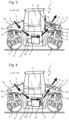
- FIG 3 shows an alternative embodiment in which, in contrast to the embodiment of the Figure 2 the cooler 10 is arranged upstream of the fan 11 in relation to the flow direction of the cooling air.
- the fan 11 sucks the cooling air through the cooler 10 and then blows it out through the ventilation openings 9 of the rear cover 17 into the outside environment of the tandem roller 1.
- the fan 11 is still arranged together with the cooler 10 in the rear machine room 19 and is operated by a separate fan drive 12.
- the cooler 10 and the fan 11 are no longer arranged in close proximity to one another and in a common interior compartment, as in the previous embodiments, but are spatially separated from one another.
- the fan 11 is arranged on a power take-off 13 of the drive motor 4 and is driven by it, for example via a belt drive.
- the fan 11 is therefore located in the drive and operating part 25 of the tandem roller 1, specifically in the engine compartment 20.
- the cooler 10, on the other hand, is still arranged in the rear machine compartment 19, i.e. outside the engine compartment 20.
- the air flow corresponds to that of the previous embodiments. In this context, it is also possible to To position the fan below the front cover and the cooler below the rear cover or vice versa.
- the flow direction of the cooling air can basically be reversed. However, it is advantageous if the cooling air is blown out at the same machine part as the exhaust gases from the combustion engine.
- a tailpipe 6 of the exhaust system of the tandem roller 1 is arranged on the second steering part 24, in other words on the rear machine part.
- the exhaust gases from the drive motor 4 are discharged from the tailpipe 6 into the outside environment of the tandem roller 1.
- the tailpipe 6 also directs the exhaust gases, for example, through the rear cover 17.
- the rear cover 17 slopes away from the driver's cab 2 and vertically downwards.
- the tailpipe 6 can be designed without a rear silencer by using the SCR device and can therefore be particularly short.
- the tail pipe 6 is designed such that the outlet opening for the exhaust gases is located vertically below or at most at the same height as the ventilation openings 9 through which the cooling air exits the machine room 19.
- the corresponding ventilation openings 9 are in turn arranged closer to the driver's cab 2 than the tail pipe 6.
- the ventilation openings 9 are located between the driver's cab 2 and the tail pipe 6.
- it can also be provided that the tail pipe 6 is surrounded on both sides by the ventilation openings 9, in particular when viewed in and/or transversely to the machine's longitudinal direction a.
- the fan 11, the cooler 10 and the ventilation openings 9 through which the cooling air exits into the outside environment of the tandem roller 1 are designed such that the cooling air is blown out in the direction away from the driver's cab 2 and diagonally upwards.
- the tail pipe 6 is also designed such that the exhaust gases exit the tail pipe 6 in this direction.
- the escaping cooling air forms a flow carpet that is located between the driver's cab 2 and the tailpipe 6 and therefore shields the driver of the tandem roller 1 from the exhaust gases. Due to the higher volume flow and the higher speed of the escaping cooling air compared to the exhaust gas flow, the exhaust gases are also captured by the escaping cooling air flow and transported further away from the driver's cab 2 and distributed in the outside environment. This also leads to a lower exhaust gas load for the driver of the tandem roller 1.
- FIGS 5 and 6 show a top view of the tandem roller 1, whereby For reasons of clarity, driver's cab 2 has been omitted.
- the Figures 5 and 6 illustrate in particular how the cooling air is guided through the tandem roller 1 via the first steering part 23, the drive and operating part 25 and the second steering part 24.
- a summary of the Figures 1 and 5 how the two liquid tanks 14 arranged on the engine compartment doors 7 are arranged. These are located on opposite sides of the tandem roller 1 and can be pivoted with the engine compartment doors 7.
- the center of gravity of the tandem roller 1 is particularly low when the liquid tanks 14 are full, which is advantageous for reasons of stability.
- the liquid tanks 14 can be easily refilled by an operator standing on the floor 8.
- a key point of the invention is that in order to enlarge the cooler 10, there is no need to reduce the size of the liquid tanks 14, but rather that the cooler 10 is arranged outside the engine compartment 20, specifically in one of the machine rooms 18, 19. In this way, only the cooling air flow has to be guided through the engine compartment 20 and in particular between the liquid tanks 14. For this purpose, a comparatively small gap between the drive motor 4 and the liquid tanks 14 is sufficient.
- the flow through the cooler 10 itself then takes place in another area of the tandem roller 1.
- Figure 6 it is an example that in principle a reverse flow of cooling air through the tandem roller 1 can also be used.
- FIG. 7 shows a flow chart of the method 30 according to the invention.
- the method 30 begins with the suction 31 of cooling air from the outside environment of the tandem roller 1 into a front or rear machine room 18, 19, preferably into the front machine room 18.
- the cooling air is then guided 32 downwards into the engine room 20 and along the machine's longitudinal axis a, preferably to the rear.
- the cooling air is then guided 33 upwards and preferably backwards in the machine's longitudinal direction a into the other front or rear machine room 18, 19, preferably the rear machine room 19.
- This is followed by the cooling air flowing 34 through a cooler 10 arranged in the front or rear machine room 18, 19, preferably in the rear machine room 19, and finally the cooling air is blown out 35 into the outside environment of the tandem roller 1.
- cooling air can be sucked in 36 through an intake duct 22 between the driver's cab 2 and ventilation openings 9, through which the cooling air flow conveyed by the fan 11 exits the outside environment of the tandem roller 1.
- the cooling air can also be blown out 35 in such a way that it is directed in the direction of the outlet of the exhaust gases from the tailpipe 6 of the exhaust system and therefore transports these exhaust gases away from the driver's cab 2 and actively mixes them with the air of the outside environment.
- the invention makes optimal use of the installation space of the tandem roller 1, particularly in the interior of the machine rooms 18, 19 and the engine room 20.
- This makes it possible to design several components of the tandem roller 1, for example the cooler 10 and the liquid tanks 14, with the largest possible volume and therefore to increase the efficiency of the machine.
- the invention makes it possible to use the cooling air flow advantageously to protect the driver of the tandem roller 1 from exhaust gases from the machine.
Landscapes
- Engineering & Computer Science (AREA)
- Architecture (AREA)
- Civil Engineering (AREA)
- Structural Engineering (AREA)
- Chemical & Material Sciences (AREA)
- Combustion & Propulsion (AREA)
- Transportation (AREA)
- Mechanical Engineering (AREA)
- Road Paving Machines (AREA)
- Cooling, Air Intake And Gas Exhaust, And Fuel Tank Arrangements In Propulsion Units (AREA)
Claims (15)
- Rouleau tandem (1) à direction articulée pour le compactage du sol, comprenant- un bâti pour machines (3) comportant un poste de conduite (2),- deux rouleaux compresseurs (5) espacés l'un de l'autre dans la direction longitudinale des machines (a) qui sont respectivement montés sur le bâti pour machines (3) de manière à pouvoir être dirigés par l'intermédiaire d'une direction articulée,- un moteur d'entraînement (4),- un refroidisseur (10), et- un ventilateur (11) associé au refroidisseur (10) et transportant un flux d'air de refroidissement,caractérisé en ce
que le refroidisseur (10) est disposé en direction verticale au-dessus de l'un des rouleaux compresseurs (5) et/ou dans la direction longitudinale des machines (a) à hauteur de l'un des rouleaux compresseurs, que, dans la direction longitudinale des machines (a), aussi bien devant que derrière le poste de conduite (2), un espace des machines (18, 19) au moins partiellement recouvert par un élément de recouvrement (16, 17) est présent, dans lequel l'élément de recouvrement avant (16) et l'élément de recouvrement arrière (17) présentent sur leur côté situé verticalement en haut des ouvertures d'aération (9) pour le flux d'air de refroidissement transporté par le ventilateur (11), et qu'un canal d'écoulement est présent, lequel est conçu de telle sorte que le flux d'air de refroidissement transporté par le ventilateur (11) est transporté depuis l'environnement extérieur du rouleau tandem (1) dans l'espace des machines avant (18), puis, depuis celui-ci, verticalement vers le bas et vers l'arrière dans un espace moteur (20) disposé sous le poste de conduite (2), puis sensiblement horizontalement à travers l'espace moteur (20), depuis celui-ci, en direction verticale vers le haut et vers l'arrière dans l'espace des machines arrière (19) et, depuis celui-ci, à nouveau dans l'environnement extérieur du rouleau tandem (1), ou inversement. - Rouleau tandem (1) selon la revendication 1,
caractérisé en ce
que le refroidisseur (10) est disposé en direction verticale au-dessus d'une articulation rotative (15) de la direction articulée de l'un des rouleaux compresseurs (5). - Rouleau tandem (1) selon l'une des revendications précédentes,
caractérisé en ce
que le refroidisseur (10) est réalisé sous forme de bloc-refroidisseurs et comprend au moins deux des refroidisseurs suivants, en particulier les trois : un refroidisseur de liquide hydraulique, un refroidisseur de liquide de refroidissement, un refroidisseur d'air de suralimentation. - Rouleau tandem (1) selon l'une des revendications précédentes,
caractérisé en ce
que le ventilateur (11) associé au refroidisseur (10) présente au moins l'une des caractéristiques suivantes :- il est disposé en direction verticale au-dessus de l'un des rouleaux compresseurs (5) et/ou dans la direction longitudinale des machines (a) au niveau de l'un des rouleaux compresseurs,- il est disposé sur un entraînement auxiliaire (13) du moteur d'entraînement (4),- il est disposé avant le refroidisseur (10) dans le sens de l'écoulement de l'air de refroidissement et souffle de l'air de refroidissement à travers le refroidisseur (10),- il est disposé derrière le refroidisseur (10) dans le sens de l'écoulement de l'air de refroidissement et aspire de l'air de refroidissement à travers le refroidisseur (10),- il peut être entraîné par un entraînement de ventilateur (12) séparé, en particulier hydraulique ou électrique, ou par un entraînement auxiliaire (13) du moteur d'entraînement (4), en particulier par l'intermédiaire d'un entraînement à courroie. - Rouleau tandem (1) selon l'une des revendications précédentes,
caractérisé en ce
que le refroidisseur (10) est disposé dans l'espace des machines avant (18) ou dans l'espace des machines arrière (19) et que le ventilateur (11) associé au refroidisseur (10) est disposé dans l'espace des machines avant (18) ou dans l'espace des machines arrière (19), dans lequel de préférence le refroidisseur (10) et le ventilateur (11) associé au refroidisseur (10) sont disposés dans l'espace des machines arrière (19). - Rouleau tandem (1) selon l'une des revendications précédentes,
caractérisé en ce
que l'espace moteur (20) est délimité des deux côtés, transversalement à la direction longitudinale des machines (a), par respectivement une porte d'espace moteur (7), dans lequel les portes d'espace moteur (7) présentent respectivement un réservoir de liquide (14), et que le flux d'air de refroidissement transporté par le ventilateur (11) est transporté entre les deux réservoirs de liquide (14), dans lequel le refroidisseur (10) est disposé à l'extérieur de la zone située entre les deux réservoirs de liquide (14). - Rouleau tandem (1) selon l'une des revendications précédentes,
caractérisé en ce
qu'entre le poste de conduite (2) et les ouvertures d'aération (9) par lesquelles le flux d'air de refroidissement transporté par le ventilateur (11) sort dans l'environnement extérieur du rouleau tandem (1) est disposé un canal d'aspiration (22) par lequel de l'air est aspiré depuis l'environnement extérieur du rouleau tandem (1) et est ajouté au flux d'air de refroidissement. - Rouleau tandem (1) selon l'une des revendications précédentes,
caractérisé en ce
que le refroidisseur (10) est disposé de telle sorte que le flux d'air de refroidissement transporté par le ventilateur (11) s'écoule à travers celui-ci en direction oblique vers le haut et à l'écart du poste de conduite (2). - Rouleau tandem (1) selon l'une des revendications précédentes,
caractérisé en ce
que les ouvertures d'aération (9) par lesquelles le flux d'air de refroidissement transporté par le ventilateur (11) sort dans l'environnement extérieur du rouleau tandem (1) sont réalisées de telle sorte que le flux d'air de refroidissement transporté par le ventilateur (11) est dirigé en direction oblique vers le haut et à l'écart du poste de conduite (2) lors de sa sortie par les ouvertures d'aération (9). - Rouleau tandem (1) selon l'une des revendications précédentes,
caractérisé en ce
que les ouvertures d'aération (9) par lesquelles le flux d'air de refroidissement transporté par le ventilateur (11) sort dans l'environnement extérieur du rouleau tandem (1) et un tuyau d'extrémité (6) d'un système d'échappement du moteur d'entraînement (4) sont disposés sur le même élément de recouvrement (16, 17), et que les ouvertures d'aération (9) sont disposées au moins partiellement plus près du poste de conduite (2) que le tuyau d'extrémité (6). - Rouleau tandem (1) selon l'une des revendications précédentes,
caractérisé en ce
que le refroidisseur (10), en particulier les refroidisseurs, sont disposés de telle sorte que le flux d'air de refroidissement s'écoule à travers ceux-ci dans une direction au moins partiellement orientée vers le haut. - Procédé (30) permettant de faire fonctionner un rouleau tandem (1) à direction articulée selon les revendications précédentes, comprenant les étapes consistant à :a) aspirer (31) de l'air de refroidissement depuis l'environnement extérieur du rouleau tandem (1) dans l'espace des moteurs avant ou arrière (18, 19) ;b) diriger (32) l'air de refroidissement vers le bas dans l'espace moteur (20) et le long de la direction longitudinale des machines (a) ;c) diriger (33) l'air de refroidissement vers le haut dans l'autre espace des machines avant ou arrière (18, 19) respectif ;d) faire s'écouler (34) l'air de refroidissement à travers le refroidisseur (10) disposé dans l'espace des machines avant ou arrière (18, 19) ; ete) souffler (35) l'air de refroidissement dans l'environnement extérieur du rouleau tandem (1).
- Procédé (30) selon la revendication 12,
caractérisé par
une aspiration (36) d'air de refroidissement par un canal d'aspiration (22) entre un poste de conduite (2) et des ouvertures d'aération (9) par lesquelles le flux d'air de refroidissement transporté par le ventilateur (11) sort dans l'environnement extérieur du rouleau tandem (1). - Procédé (30) selon l'une des revendications 12 à 13,
caractérisé en ce
que l'aspiration (31) de l'air de refroidissement est effectuée de manière oblique vers le bas et/ou l'écoulement (34) de l'air de refroidissement est effectué de manière oblique vers le haut et/ou le soufflage (35) de l'air de refroidissement est effectué de manière oblique vers le haut et à l'écart du poste de conduite (2). - Procédé (30) selon l'une des revendications 12 à 14,
caractérisé en ce
que le soufflage (35) de l'air de refroidissement dans l'environnement extérieur du rouleau tandem (1) est effectué de telle sorte que le flux d'air de refroidissement est dirigé en direction d'un tuyau d'extrémité (6) d'un système d'échappement du moteur d'entraînement (4).
Applications Claiming Priority (1)
| Application Number | Priority Date | Filing Date | Title |
|---|---|---|---|
| DE102020004615.0A DE102020004615A1 (de) | 2020-07-29 | 2020-07-29 | Schemelgelenkte tandemwalze und verfahren zum betrieb derartiger walzen |
Publications (2)
| Publication Number | Publication Date |
|---|---|
| EP3945158A1 EP3945158A1 (fr) | 2022-02-02 |
| EP3945158B1 true EP3945158B1 (fr) | 2025-02-19 |
Family
ID=76744753
Family Applications (1)
| Application Number | Title | Priority Date | Filing Date |
|---|---|---|---|
| EP21183242.3A Active EP3945158B1 (fr) | 2020-07-29 | 2021-07-01 | Rouleau tandem à traverse pivotante et procédé de fonctionnement de tels rouleaux |
Country Status (4)
| Country | Link |
|---|---|
| US (1) | US12180659B2 (fr) |
| EP (1) | EP3945158B1 (fr) |
| CN (1) | CN114059418A (fr) |
| DE (1) | DE102020004615A1 (fr) |
Families Citing this family (3)
| Publication number | Priority date | Publication date | Assignee | Title |
|---|---|---|---|---|
| US20210329855A1 (en) * | 2020-04-22 | 2021-10-28 | Richard Charles Kalil, JR. | Apparatus for the Automated Repair of Pitch Marks |
| DE102021212546A1 (de) * | 2021-11-08 | 2023-05-11 | Bomag Gmbh | Tandemwalze zur Verdichtung eines Bodenuntergrundes |
| JP7759265B2 (ja) * | 2022-01-20 | 2025-10-23 | 株式会社やまびこ | 動力作業機 |
Family Cites Families (20)
| Publication number | Priority date | Publication date | Assignee | Title |
|---|---|---|---|---|
| US3868194A (en) * | 1974-02-06 | 1975-02-25 | Iowa Mfg Co | Expandable articulated tandem roller |
| US3947142A (en) * | 1975-02-06 | 1976-03-30 | Raygo, Inc. | Articulated pavement compacting machine |
| CS178671B1 (en) | 1975-09-23 | 1977-10-31 | Stanislav Venc | Frame for vibrating tandem roller |
| US4046485A (en) * | 1975-12-09 | 1977-09-06 | William H. Clark | Earth and road roller with oppositely skewed tandem steering drums |
| AT363120B (de) * | 1978-03-03 | 1981-07-10 | Voest Alpine Ag | Strassenwalze |
| US4266884A (en) * | 1979-05-07 | 1981-05-12 | Dynapac Maskin Ab | Resiliently mounted steering yoke for road roller |
| US5337833A (en) * | 1992-11-30 | 1994-08-16 | Rizzo Salvatore J | Machine for smoothing ground surfaces |
| AUPO241496A0 (en) * | 1996-09-18 | 1996-10-10 | Pioneer Road Services Pty. Ltd. | Method and apparatus for asphalt compaction |
| DE29620847U1 (de) | 1996-11-30 | 1997-01-23 | Bomag GmbH, 56154 Boppard | Motorbetriebenes Bodenverdichtungsgerät |
| DE29805539U1 (de) * | 1998-03-26 | 1998-06-18 | Vibromax Bodenverdichtungsmaschinen GmbH, 06466 Gatersleben | Bodenverdichtungsmaschine |
| JP4450298B2 (ja) * | 2000-01-12 | 2010-04-14 | 株式会社小松製作所 | 建設機械のエンジン冷却風路 |
| DE20020088U1 (de) * | 2000-11-27 | 2001-02-15 | Vibromax Bodenverdichtungsmaschinen GmbH, 06466 Gatersleben | Bodenverdichtungsmaschine |
| US8104559B2 (en) * | 2008-09-22 | 2012-01-31 | Clark Equipment Company | Multiple air flow paths using single axial fan |
| DE102009002998A1 (de) * | 2009-05-11 | 2010-11-18 | Robert Bosch Gmbh | Kraftfahrzeug-Kühleinrichtung und Kühlsystem |
| DE102010035131A1 (de) * | 2010-08-23 | 2012-02-23 | Bomag Gmbh | Vorrichtung zur gelenkigen Verbindung von zwei Fahrzeugrahmen einer Baumaschine |
| DE102011005275A1 (de) * | 2011-03-09 | 2012-09-13 | Hamm Ag | Selbstfahrendes Baugerät, insbesondere Bodenverdichter |
| EP2698305B1 (fr) * | 2012-08-13 | 2015-11-04 | BOMAG GmbH | Rouleau compresseur |
| CN104590002B (zh) * | 2015-01-09 | 2017-02-22 | 徐工集团工程机械股份有限公司道路机械分公司 | 一种车辆动力舱空气导流装置 |
| CN106956587B (zh) * | 2017-01-20 | 2020-03-20 | 徐工集团工程机械有限公司 | 车辆动力舱及具有其的工程车辆 |
| JP6685261B2 (ja) * | 2017-08-28 | 2020-04-22 | 日立建機株式会社 | 転圧機械 |
-
2020
- 2020-07-29 DE DE102020004615.0A patent/DE102020004615A1/de active Pending
-
2021
- 2021-07-01 EP EP21183242.3A patent/EP3945158B1/fr active Active
- 2021-07-28 US US17/443,835 patent/US12180659B2/en active Active
- 2021-07-29 CN CN202110862360.2A patent/CN114059418A/zh active Pending
Also Published As
| Publication number | Publication date |
|---|---|
| CN114059418A (zh) | 2022-02-18 |
| EP3945158A1 (fr) | 2022-02-02 |
| US12180659B2 (en) | 2024-12-31 |
| US20220034047A1 (en) | 2022-02-03 |
| DE102020004615A1 (de) | 2022-02-03 |
Similar Documents
| Publication | Publication Date | Title |
|---|---|---|
| EP3945158B1 (fr) | Rouleau tandem à traverse pivotante et procédé de fonctionnement de tels rouleaux | |
| DE69401565T2 (de) | Schallgedämpfte Anlage für wassergekühlte Brennkraftmaschine mit Stromgenerator | |
| EP0515924B1 (fr) | Unité d'échangeur de chaleur-ventilateur compacte | |
| DE60200266T2 (de) | Motorgenerator | |
| DE3825071C1 (fr) | ||
| DE112012000007B4 (de) | Baumaschine | |
| DE2041163C3 (de) | Motorverkleidung zur Führung von angesaugter Kühlluft für eine Brennkraftmaschine eines Mähdreschers | |
| DE60132150T2 (de) | Motorfahrzeug mit Lufteinlass | |
| DE7801352U1 (de) | Zugmaschine mit einem mehrfach unterteilten brennkraftmaschinenraum | |
| DE102014008749A1 (de) | Bodenfräsmaschine mit kühlsystem, kühlsystem und verfahren zur kühlung einer bodenfräsmaschine | |
| DE2620774A1 (de) | Kraftfahrzeug mit schalldaemmend verkleidetem motor | |
| EP2479398B1 (fr) | Finisseur de route ou chargeur | |
| DE102008037934B4 (de) | Maschine mit Kühlsystem und Verfahren dafür | |
| WO1999048716A1 (fr) | Compacteur routier | |
| EP4067575B1 (fr) | Machine de traitement du sol automotrice à refroidissement de l'échangeur de chaleur et à aération du compartiment moteur combinés | |
| DE2912386C2 (fr) | ||
| DE2757966A1 (de) | Luftfuehrung fuer ein kraftfahrzeug | |
| DE3110447C2 (fr) | ||
| DE602005005148T2 (de) | Kühlvorrichtung für eine Antriebsmaschine eines Fahrzeugs | |
| DE10247704B4 (de) | Kraftfahrzeug mit Motorvollkapselung | |
| EP3060417A1 (fr) | Véhicule automobile muni d'un refroidissement supplémentaire | |
| AT511972A2 (de) | Leitblech oder Kanal für eine Kühlbaugruppe | |
| EP4071302B1 (fr) | Fraiseuse autonome pour découper les sols | |
| DE2261026A1 (de) | Bewetterung fuer einen stollen oder dergl | |
| DE112015000025T5 (de) | Hydraulikbagger |
Legal Events
| Date | Code | Title | Description |
|---|---|---|---|
| PUAI | Public reference made under article 153(3) epc to a published international application that has entered the european phase |
Free format text: ORIGINAL CODE: 0009012 |
|
| STAA | Information on the status of an ep patent application or granted ep patent |
Free format text: STATUS: THE APPLICATION HAS BEEN PUBLISHED |
|
| AK | Designated contracting states |
Kind code of ref document: A1 Designated state(s): AL AT BE BG CH CY CZ DE DK EE ES FI FR GB GR HR HU IE IS IT LI LT LU LV MC MK MT NL NO PL PT RO RS SE SI SK SM TR |
|
| STAA | Information on the status of an ep patent application or granted ep patent |
Free format text: STATUS: REQUEST FOR EXAMINATION WAS MADE |
|
| 17P | Request for examination filed |
Effective date: 20220429 |
|
| RBV | Designated contracting states (corrected) |
Designated state(s): AL AT BE BG CH CY CZ DE DK EE ES FI FR GB GR HR HU IE IS IT LI LT LU LV MC MK MT NL NO PL PT RO RS SE SI SK SM TR |
|
| STAA | Information on the status of an ep patent application or granted ep patent |
Free format text: STATUS: EXAMINATION IS IN PROGRESS |
|
| 17Q | First examination report despatched |
Effective date: 20230323 |
|
| GRAP | Despatch of communication of intention to grant a patent |
Free format text: ORIGINAL CODE: EPIDOSNIGR1 |
|
| STAA | Information on the status of an ep patent application or granted ep patent |
Free format text: STATUS: GRANT OF PATENT IS INTENDED |
|
| INTG | Intention to grant announced |
Effective date: 20241017 |
|
| GRAS | Grant fee paid |
Free format text: ORIGINAL CODE: EPIDOSNIGR3 |
|
| GRAA | (expected) grant |
Free format text: ORIGINAL CODE: 0009210 |
|
| STAA | Information on the status of an ep patent application or granted ep patent |
Free format text: STATUS: THE PATENT HAS BEEN GRANTED |
|
| AK | Designated contracting states |
Kind code of ref document: B1 Designated state(s): AL AT BE BG CH CY CZ DE DK EE ES FI FR GB GR HR HU IE IS IT LI LT LU LV MC MK MT NL NO PL PT RO RS SE SI SK SM TR |
|
| REG | Reference to a national code |
Ref country code: GB Ref legal event code: FG4D Free format text: NOT ENGLISH |
|
| REG | Reference to a national code |
Ref country code: CH Ref legal event code: EP |
|
| REG | Reference to a national code |
Ref country code: IE Ref legal event code: FG4D Free format text: LANGUAGE OF EP DOCUMENT: GERMAN |
|
| REG | Reference to a national code |
Ref country code: DE Ref legal event code: R096 Ref document number: 502021006676 Country of ref document: DE |
|
| P01 | Opt-out of the competence of the unified patent court (upc) registered |
Free format text: CASE NUMBER: APP_7638/2025 Effective date: 20250214 |
|
| REG | Reference to a national code |
Ref country code: NL Ref legal event code: MP Effective date: 20250219 |
|
| PG25 | Lapsed in a contracting state [announced via postgrant information from national office to epo] |
Ref country code: RS Free format text: LAPSE BECAUSE OF FAILURE TO SUBMIT A TRANSLATION OF THE DESCRIPTION OR TO PAY THE FEE WITHIN THE PRESCRIBED TIME-LIMIT Effective date: 20250519 |
|
| PG25 | Lapsed in a contracting state [announced via postgrant information from national office to epo] |
Ref country code: FI Free format text: LAPSE BECAUSE OF FAILURE TO SUBMIT A TRANSLATION OF THE DESCRIPTION OR TO PAY THE FEE WITHIN THE PRESCRIBED TIME-LIMIT Effective date: 20250219 |
|
| PG25 | Lapsed in a contracting state [announced via postgrant information from national office to epo] |
Ref country code: PL Free format text: LAPSE BECAUSE OF FAILURE TO SUBMIT A TRANSLATION OF THE DESCRIPTION OR TO PAY THE FEE WITHIN THE PRESCRIBED TIME-LIMIT Effective date: 20250219 |
|
| PG25 | Lapsed in a contracting state [announced via postgrant information from national office to epo] |
Ref country code: ES Free format text: LAPSE BECAUSE OF FAILURE TO SUBMIT A TRANSLATION OF THE DESCRIPTION OR TO PAY THE FEE WITHIN THE PRESCRIBED TIME-LIMIT Effective date: 20250219 |
|
| REG | Reference to a national code |
Ref country code: LT Ref legal event code: MG9D |
|
| PG25 | Lapsed in a contracting state [announced via postgrant information from national office to epo] |
Ref country code: IS Free format text: LAPSE BECAUSE OF FAILURE TO SUBMIT A TRANSLATION OF THE DESCRIPTION OR TO PAY THE FEE WITHIN THE PRESCRIBED TIME-LIMIT Effective date: 20250619 Ref country code: NO Free format text: LAPSE BECAUSE OF FAILURE TO SUBMIT A TRANSLATION OF THE DESCRIPTION OR TO PAY THE FEE WITHIN THE PRESCRIBED TIME-LIMIT Effective date: 20250519 |
|
| PG25 | Lapsed in a contracting state [announced via postgrant information from national office to epo] |
Ref country code: NL Free format text: LAPSE BECAUSE OF FAILURE TO SUBMIT A TRANSLATION OF THE DESCRIPTION OR TO PAY THE FEE WITHIN THE PRESCRIBED TIME-LIMIT Effective date: 20250219 |
|
| PG25 | Lapsed in a contracting state [announced via postgrant information from national office to epo] |
Ref country code: HR Free format text: LAPSE BECAUSE OF FAILURE TO SUBMIT A TRANSLATION OF THE DESCRIPTION OR TO PAY THE FEE WITHIN THE PRESCRIBED TIME-LIMIT Effective date: 20250219 |
|
| PG25 | Lapsed in a contracting state [announced via postgrant information from national office to epo] |
Ref country code: LV Free format text: LAPSE BECAUSE OF FAILURE TO SUBMIT A TRANSLATION OF THE DESCRIPTION OR TO PAY THE FEE WITHIN THE PRESCRIBED TIME-LIMIT Effective date: 20250219 Ref country code: PT Free format text: LAPSE BECAUSE OF FAILURE TO SUBMIT A TRANSLATION OF THE DESCRIPTION OR TO PAY THE FEE WITHIN THE PRESCRIBED TIME-LIMIT Effective date: 20250620 |
|
| PG25 | Lapsed in a contracting state [announced via postgrant information from national office to epo] |
Ref country code: GR Free format text: LAPSE BECAUSE OF FAILURE TO SUBMIT A TRANSLATION OF THE DESCRIPTION OR TO PAY THE FEE WITHIN THE PRESCRIBED TIME-LIMIT Effective date: 20250520 Ref country code: BG Free format text: LAPSE BECAUSE OF FAILURE TO SUBMIT A TRANSLATION OF THE DESCRIPTION OR TO PAY THE FEE WITHIN THE PRESCRIBED TIME-LIMIT Effective date: 20250219 |
|
| PGFP | Annual fee paid to national office [announced via postgrant information from national office to epo] |
Ref country code: CZ Payment date: 20250619 Year of fee payment: 5 |
|
| PG25 | Lapsed in a contracting state [announced via postgrant information from national office to epo] |
Ref country code: SE Free format text: LAPSE BECAUSE OF FAILURE TO SUBMIT A TRANSLATION OF THE DESCRIPTION OR TO PAY THE FEE WITHIN THE PRESCRIBED TIME-LIMIT Effective date: 20250219 |
|
| PG25 | Lapsed in a contracting state [announced via postgrant information from national office to epo] |
Ref country code: SM Free format text: LAPSE BECAUSE OF FAILURE TO SUBMIT A TRANSLATION OF THE DESCRIPTION OR TO PAY THE FEE WITHIN THE PRESCRIBED TIME-LIMIT Effective date: 20250219 |
|
| PG25 | Lapsed in a contracting state [announced via postgrant information from national office to epo] |
Ref country code: DK Free format text: LAPSE BECAUSE OF FAILURE TO SUBMIT A TRANSLATION OF THE DESCRIPTION OR TO PAY THE FEE WITHIN THE PRESCRIBED TIME-LIMIT Effective date: 20250219 |
|
| PG25 | Lapsed in a contracting state [announced via postgrant information from national office to epo] |
Ref country code: IT Free format text: LAPSE BECAUSE OF FAILURE TO SUBMIT A TRANSLATION OF THE DESCRIPTION OR TO PAY THE FEE WITHIN THE PRESCRIBED TIME-LIMIT Effective date: 20250219 |
|
| PGFP | Annual fee paid to national office [announced via postgrant information from national office to epo] |
Ref country code: AT Payment date: 20251020 Year of fee payment: 5 |
|
| PGFP | Annual fee paid to national office [announced via postgrant information from national office to epo] |
Ref country code: CH Payment date: 20250801 Year of fee payment: 5 |
|
| PG25 | Lapsed in a contracting state [announced via postgrant information from national office to epo] |
Ref country code: EE Free format text: LAPSE BECAUSE OF FAILURE TO SUBMIT A TRANSLATION OF THE DESCRIPTION OR TO PAY THE FEE WITHIN THE PRESCRIBED TIME-LIMIT Effective date: 20250219 |
|
| PG25 | Lapsed in a contracting state [announced via postgrant information from national office to epo] |
Ref country code: RO Free format text: LAPSE BECAUSE OF FAILURE TO SUBMIT A TRANSLATION OF THE DESCRIPTION OR TO PAY THE FEE WITHIN THE PRESCRIBED TIME-LIMIT Effective date: 20250219 |
|
| PG25 | Lapsed in a contracting state [announced via postgrant information from national office to epo] |
Ref country code: SK Free format text: LAPSE BECAUSE OF FAILURE TO SUBMIT A TRANSLATION OF THE DESCRIPTION OR TO PAY THE FEE WITHIN THE PRESCRIBED TIME-LIMIT Effective date: 20250219 |
|
| REG | Reference to a national code |
Ref country code: DE Ref legal event code: R097 Ref document number: 502021006676 Country of ref document: DE |
|
| PLBE | No opposition filed within time limit |
Free format text: ORIGINAL CODE: 0009261 |
|
| STAA | Information on the status of an ep patent application or granted ep patent |
Free format text: STATUS: NO OPPOSITION FILED WITHIN TIME LIMIT |
|
| 26N | No opposition filed |
Effective date: 20251120 |
|
| PG25 | Lapsed in a contracting state [announced via postgrant information from national office to epo] |
Ref country code: LU Free format text: LAPSE BECAUSE OF NON-PAYMENT OF DUE FEES Effective date: 20250701 |
|
| GBPC | Gb: european patent ceased through non-payment of renewal fee |
Effective date: 20250701 |
|
| REG | Reference to a national code |
Ref country code: BE Ref legal event code: MM Effective date: 20250731 |
|
| PG25 | Lapsed in a contracting state [announced via postgrant information from national office to epo] |
Ref country code: GB Free format text: LAPSE BECAUSE OF NON-PAYMENT OF DUE FEES Effective date: 20250701 |
|
| PGFP | Annual fee paid to national office [announced via postgrant information from national office to epo] |
Ref country code: DE Payment date: 20260120 Year of fee payment: 5 |
|
| PG25 | Lapsed in a contracting state [announced via postgrant information from national office to epo] |
Ref country code: BE Free format text: LAPSE BECAUSE OF NON-PAYMENT OF DUE FEES Effective date: 20250731 |
|
| PG25 | Lapsed in a contracting state [announced via postgrant information from national office to epo] |
Ref country code: FR Free format text: LAPSE BECAUSE OF NON-PAYMENT OF DUE FEES Effective date: 20250731 |