EP3948002B1 - Rotationsvorrichtung mit kupplung mit zeitbasiertem schlupf und verfahren zur bereitstellung von zeitbasiertem schlupf für eine rotationsvorrichtung - Google Patents
Rotationsvorrichtung mit kupplung mit zeitbasiertem schlupf und verfahren zur bereitstellung von zeitbasiertem schlupf für eine rotationsvorrichtung Download PDFInfo
- Publication number
- EP3948002B1 EP3948002B1 EP20777522.2A EP20777522A EP3948002B1 EP 3948002 B1 EP3948002 B1 EP 3948002B1 EP 20777522 A EP20777522 A EP 20777522A EP 3948002 B1 EP3948002 B1 EP 3948002B1
- Authority
- EP
- European Patent Office
- Prior art keywords
- decoupler
- clutch
- input member
- wrap spring
- acceleration
- Prior art date
- Legal status (The legal status is an assumption and is not a legal conclusion. Google has not performed a legal analysis and makes no representation as to the accuracy of the status listed.)
- Active
Links
Images


Classifications
-
- B—PERFORMING OPERATIONS; TRANSPORTING
- B60—VEHICLES IN GENERAL
- B60K—ARRANGEMENT OR MOUNTING OF PROPULSION UNITS OR OF TRANSMISSIONS IN VEHICLES; ARRANGEMENT OR MOUNTING OF PLURAL DIVERSE PRIME-MOVERS IN VEHICLES; AUXILIARY DRIVES FOR VEHICLES; INSTRUMENTATION OR DASHBOARDS FOR VEHICLES; ARRANGEMENTS IN CONNECTION WITH COOLING, AIR INTAKE, GAS EXHAUST OR FUEL SUPPLY OF PROPULSION UNITS IN VEHICLES
- B60K25/00—Auxiliary drives
- B60K25/02—Auxiliary drives directly from an engine shaft
-
- F—MECHANICAL ENGINEERING; LIGHTING; HEATING; WEAPONS; BLASTING
- F02—COMBUSTION ENGINES; HOT-GAS OR COMBUSTION-PRODUCT ENGINE PLANTS
- F02B—INTERNAL-COMBUSTION PISTON ENGINES; COMBUSTION ENGINES IN GENERAL
- F02B67/00—Engines characterised by the arrangement of auxiliary apparatus not being otherwise provided for, e.g. the apparatus having different functions; Driving auxiliary apparatus from engines, not otherwise provided for
- F02B67/04—Engines characterised by the arrangement of auxiliary apparatus not being otherwise provided for, e.g. the apparatus having different functions; Driving auxiliary apparatus from engines, not otherwise provided for of mechanically-driven auxiliary apparatus
- F02B67/06—Engines characterised by the arrangement of auxiliary apparatus not being otherwise provided for, e.g. the apparatus having different functions; Driving auxiliary apparatus from engines, not otherwise provided for of mechanically-driven auxiliary apparatus driven by means of chains, belts, or like endless members
-
- F—MECHANICAL ENGINEERING; LIGHTING; HEATING; WEAPONS; BLASTING
- F16—ENGINEERING ELEMENTS AND UNITS; GENERAL MEASURES FOR PRODUCING AND MAINTAINING EFFECTIVE FUNCTIONING OF MACHINES OR INSTALLATIONS; THERMAL INSULATION IN GENERAL
- F16D—COUPLINGS FOR TRANSMITTING ROTATION; CLUTCHES; BRAKES
- F16D13/00—Friction clutches
- F16D13/12—Friction clutches with an expansible band or coil co-operating with the inner surface of a drum or the like
-
- F—MECHANICAL ENGINEERING; LIGHTING; HEATING; WEAPONS; BLASTING
- F16—ENGINEERING ELEMENTS AND UNITS; GENERAL MEASURES FOR PRODUCING AND MAINTAINING EFFECTIVE FUNCTIONING OF MACHINES OR INSTALLATIONS; THERMAL INSULATION IN GENERAL
- F16D—COUPLINGS FOR TRANSMITTING ROTATION; CLUTCHES; BRAKES
- F16D41/00—Freewheels or freewheel clutches
- F16D41/20—Freewheels or freewheel clutches with expandable or contractable clamping ring or band
- F16D41/206—Freewheels or freewheel clutches with expandable or contractable clamping ring or band having axially adjacent coils, e.g. helical wrap-springs
-
- F—MECHANICAL ENGINEERING; LIGHTING; HEATING; WEAPONS; BLASTING
- F16—ENGINEERING ELEMENTS AND UNITS; GENERAL MEASURES FOR PRODUCING AND MAINTAINING EFFECTIVE FUNCTIONING OF MACHINES OR INSTALLATIONS; THERMAL INSULATION IN GENERAL
- F16D—COUPLINGS FOR TRANSMITTING ROTATION; CLUTCHES; BRAKES
- F16D7/00—Slip couplings, e.g. slipping on overload, for absorbing shock
- F16D7/02—Slip couplings, e.g. slipping on overload, for absorbing shock of the friction type
-
- F—MECHANICAL ENGINEERING; LIGHTING; HEATING; WEAPONS; BLASTING
- F16—ENGINEERING ELEMENTS AND UNITS; GENERAL MEASURES FOR PRODUCING AND MAINTAINING EFFECTIVE FUNCTIONING OF MACHINES OR INSTALLATIONS; THERMAL INSULATION IN GENERAL
- F16H—GEARING
- F16H7/00—Gearings for conveying rotary motion by endless flexible members
- F16H7/18—Means for guiding or supporting belts, ropes, or chains
- F16H7/20—Mountings for rollers or pulleys
-
- B—PERFORMING OPERATIONS; TRANSPORTING
- B60—VEHICLES IN GENERAL
- B60K—ARRANGEMENT OR MOUNTING OF PROPULSION UNITS OR OF TRANSMISSIONS IN VEHICLES; ARRANGEMENT OR MOUNTING OF PLURAL DIVERSE PRIME-MOVERS IN VEHICLES; AUXILIARY DRIVES FOR VEHICLES; INSTRUMENTATION OR DASHBOARDS FOR VEHICLES; ARRANGEMENTS IN CONNECTION WITH COOLING, AIR INTAKE, GAS EXHAUST OR FUEL SUPPLY OF PROPULSION UNITS IN VEHICLES
- B60K25/00—Auxiliary drives
- B60K25/02—Auxiliary drives directly from an engine shaft
- B60K2025/022—Auxiliary drives directly from an engine shaft by a mechanical transmission
-
- F—MECHANICAL ENGINEERING; LIGHTING; HEATING; WEAPONS; BLASTING
- F16—ENGINEERING ELEMENTS AND UNITS; GENERAL MEASURES FOR PRODUCING AND MAINTAINING EFFECTIVE FUNCTIONING OF MACHINES OR INSTALLATIONS; THERMAL INSULATION IN GENERAL
- F16D—COUPLINGS FOR TRANSMITTING ROTATION; CLUTCHES; BRAKES
- F16D3/00—Yielding couplings, i.e. with means permitting movement between the connected parts during the drive
- F16D3/02—Yielding couplings, i.e. with means permitting movement between the connected parts during the drive adapted to specific functions
- F16D3/14—Yielding couplings, i.e. with means permitting movement between the connected parts during the drive adapted to specific functions combined with a friction coupling for damping vibration or absorbing shock
-
- F—MECHANICAL ENGINEERING; LIGHTING; HEATING; WEAPONS; BLASTING
- F16—ENGINEERING ELEMENTS AND UNITS; GENERAL MEASURES FOR PRODUCING AND MAINTAINING EFFECTIVE FUNCTIONING OF MACHINES OR INSTALLATIONS; THERMAL INSULATION IN GENERAL
- F16D—COUPLINGS FOR TRANSMITTING ROTATION; CLUTCHES; BRAKES
- F16D43/00—Automatic clutches
- F16D43/02—Automatic clutches actuated entirely mechanically
- F16D43/20—Automatic clutches actuated entirely mechanically controlled by torque, e.g. overload-release clutches, slip-clutches with means by which torque varies the clutching pressure
- F16D43/21—Automatic clutches actuated entirely mechanically controlled by torque, e.g. overload-release clutches, slip-clutches with means by which torque varies the clutching pressure with friction members
- F16D43/211—Automatic clutches actuated entirely mechanically controlled by torque, e.g. overload-release clutches, slip-clutches with means by which torque varies the clutching pressure with friction members with radially applied torque-limiting friction surfaces
-
- F—MECHANICAL ENGINEERING; LIGHTING; HEATING; WEAPONS; BLASTING
- F16—ENGINEERING ELEMENTS AND UNITS; GENERAL MEASURES FOR PRODUCING AND MAINTAINING EFFECTIVE FUNCTIONING OF MACHINES OR INSTALLATIONS; THERMAL INSULATION IN GENERAL
- F16D—COUPLINGS FOR TRANSMITTING ROTATION; CLUTCHES; BRAKES
- F16D7/00—Slip couplings, e.g. slipping on overload, for absorbing shock
- F16D7/02—Slip couplings, e.g. slipping on overload, for absorbing shock of the friction type
- F16D7/021—Slip couplings, e.g. slipping on overload, for absorbing shock of the friction type with radially applied torque-limiting friction surfaces
-
- F—MECHANICAL ENGINEERING; LIGHTING; HEATING; WEAPONS; BLASTING
- F16—ENGINEERING ELEMENTS AND UNITS; GENERAL MEASURES FOR PRODUCING AND MAINTAINING EFFECTIVE FUNCTIONING OF MACHINES OR INSTALLATIONS; THERMAL INSULATION IN GENERAL
- F16D—COUPLINGS FOR TRANSMITTING ROTATION; CLUTCHES; BRAKES
- F16D7/00—Slip couplings, e.g. slipping on overload, for absorbing shock
- F16D7/02—Slip couplings, e.g. slipping on overload, for absorbing shock of the friction type
- F16D7/022—Slip couplings, e.g. slipping on overload, for absorbing shock of the friction type with a helical band or equivalent member co-operating with a cylindrical torque limiting coupling surface
Definitions
- the invention relates generally to rotary devices with clutches that are mounted on accessory drives for engines.
- the invention relates to decouplers on accessory drives for vehicular engines.
- the present invention provides a decoupler having the features defined in claim 1. Further it is provided a method for controlling torque to an accessories in an accessory drive on an engine. The method has the features defined in claim 5. Further preferred embodiments are defined in the dependent claims.
- FIG. 1 shows an engine 10 for a vehicle.
- the engine 10 includes a crankshaft 12 which drives an endless drive element, which may be, for example, a belt 14. Via the belt 14, the engine 10 drives a plurality of accessories 16 (shown in dashed outlines), such as an alternator and an air conditioning compressor.
- Each accessory 16 includes an accessory shaft 15 with a pulley 13 thereon, which is driven by the belt 14.
- shown in the present embodiment is an idler pulley shown at 17a on an idler shaft 17b, and a tensioner pulley 19a rotatably mounted on a tensioner arm 19b, which form part of a tensioner 19.
- the functions of the idler pulley 17a and the tensioner 19 are well known to one of skill in the art.
- a decoupler 20 may be provided instead of a pulley, between the belt 14 and the accessory shaft 15 of any one or more of the belt driven accessories 16.
- a decoupler 20 provided on the accessory shaft 15 of the alternator (shown at 16a).
- the decoupler 20 transfers torque between the belt 14 and the accessory shaft 15 but automatically decouples the accessory shaft 15 from the belt 14 when the belt 14 decelerates relative to the accessory shaft 15.
- the decoupler 20 allows the speed of the belt 14 to oscillate relative to the accessory shaft 15. Oscillations in the speed of the belt 14 are the result of oscillations in the speed of the crankshaft 12, which is inherent to internal combustion piston engines. These oscillations are isolated from the accessory shaft 15 by the decoupler 20, and as a result, the stresses that would otherwise be incurred by the accessory shaft 15 and the accessory 16 are reduced.
- FIG. 2 shows an exploded view of the decoupler 20, and Figure 3 , which shows a sectional view of the decoupler 20.
- the decoupler 20 includes a shaft adapter 22, a pulley 24, an isolation spring 28, and a wrap spring clutch 32.
- the decoupler 20 further includes optional elements including a bearing 26, a bushing 27, a sleeve 29, a carrier 30, an end cap 34 and a thrust plate 35.
- the shaft adapter 22 is adapted to mount to the accessory shaft 15 in any suitable way.
- the shaft adapter 22 may have a shaft-mounting aperture 36 therethrough that defines a rotational axis A for the decoupler 20.
- the shaft mounting aperture 36 may be configured to snugly receive the end of the accessory shaft 15.
- the shaft in Figure 3 is shown only partially inserted into the shaft-mounting aperture 36.
- a shaft-mounting fastener (not shown) may be inserted through a distal end 38 of the aperture 36 to fixedly mount the shaft adapter 22 to the accessory shaft 15 so that the two co-rotate together about the axis A.
- the pulley 24 is rotatably coupled to the shaft adapter 22.
- the pulley 24 has an outer surface which includes a belt engagement surface 40 that is configured to engage the belt 14 ( Figure 1 ).
- the belt 14 may thus be a multiple-V belt.
- the pulley 24 further includes an inner surface 43.
- the bearing 26 and the bushing 27 engage the inner surface 43 of the pulley 24 and rotatably support the pulley 24 on the shaft adapter 22.
- the bearing 26 may be any suitable type of bearing, such as a sealed ball bearing.
- the isolation spring 28 is provided to accommodate oscillations in the speed of the belt 14 relative to the accessory shaft 15.
- the isolation spring 28 is a helical torsion spring that has a first end 49 ( Figure 2 ) that is held in an annular slot 50 and that abuts a radial wall (not shown) in the shaft adapter 22 for torque transfer therewith.
- the isolation spring 28 has a second end 52 that is positioned in the carrier 30 to transfer torque with an end of the wrap spring clutch, as described further below.
- the isolation spring 28 further includes a plurality of coils 58 between the first and second ends 49 and 52.
- An example of a suitable engagement between the isolation spring 28, the shaft adapter 22 and the carrier 30 is shown and described in US Patent 7,712,592 .
- the isolation spring 28 in the embodiment shown is an opening spring, which means that, as the torque transmitted through the isolation spring 28 increases, the isolation spring 28 opens or expands radially.
- the isolation spring 28 may be compressed axially slightly in the decoupler 20 such that it urges the carrier 30 axially into abutment with the thrust plate 35, which is in abutment with the bearing 26, which is itself press-fit between the shaft adapter 22 and the pulley 24.
- the wrap spring clutch 32 is a helical member that has a first end 60 ( Figure 4 ), also referred to as a spring engagement end 60, that is held in the carrier 30 for engagement with the second end 52 of the isolation spring 28, for torque transfer therewith.
- the wrap spring clutch 32 has a second end 64 that may be referred to as the free end 64 that is, broadly speaking, positioned to transfer torque with the inner surface 43 of the pulley 24, and a plurality of coils 66 between the first and second ends 60 and 64.
- the wrap spring clutch 32 has a radially outer surface 67, which is an outer surface of the plurality of coils 66, and a radially inner surface 69, which is an inner surface of the plurality of coils 66.
- the wrap spring clutch 32 permits the pulley 24 to drive the accessory shaft during rotation of the pulley 24 in a drive direction, while permitting the accessory shaft to overrun the pulley 24 in the drive direction (e.g. during shut down of the engine 10).
- a torque path is provided from the pulley 24 through the wrap spring clutch 32, through the isolation spring 29 and into the shaft adapter 22.
- the wrap spring clutch and the isolation spring act in series in a torque path between the pulley 24 and the shaft adapter 22.
- the pulley 24 may be considered to be just an example of a suitable decoupler input member
- the shaft adapter 22 may be considered to be just an example of a suitable decoupler output member.
- the wrap spring clutch 32 and the isolation spring 28 act in series in a torque path between the decoupler input member and the decoupler output member.
- the isolation spring 28 is radially spaced from the wrap spring clutch 32 by the sleeve 57.
- the sleeve 57 is, in the embodiment shown, a polymeric member having a hollow cylindrical shape with an axial slot 68 therethrough, so as to permit the sleeve 57 to expand and contract as needed.
- the sleeve 57 could have any other suitable shape, such as a shape formed by a helically coiled wire.
- the sleeve 57 acts as a torque limiter by limiting the amount of room available for radial expansion of the isolation spring 28 (in embodiments wherein the isolation spring 28 is an opening spring).
- the isolation spring 28 expands and engages the sleeve 57.
- the isolation spring 28 then expands further, causing expansion of the sleeve 57 until the sleeve 57 engages the radially inner 69 of the wrap spring clutch 32, which constrains the sleeve 57 from further expansion.
- the sleeve 57 then constrains the isolation spring 28 against further radial expansion.
- the sleeve 57 may be made from any suitable material such as a polymeric material, such as a nylon, for example. An example of a suitable sleeve 57 is shown and described in US Patent 7,766,774 .
- one of the radially inner and outer surfaces 67 and 69 of the wrap spring clutch engages a surface of the pulley 24 in an interference fit.
- the radially outer surface 67 of the wrap spring clutch engages the inner surface 43 of the pulley in the aforementioned interference fit.
- the inner surface of the pulley may thus be referred to as a clutch engagement surface.
- the pulley 24 it is possible for the pulley 24 to have a radially outer surface that is the clutch engagement surface and which is engaged by the radially inner surface 69 of the wrap spring clutch 32 in an interference fit.
- the first end 60 of the wrap spring clutch 32 transmits the torque from the pulley 24 to the isolation spring 28, which in turn transmits the torque to the shaft adapter 22.
- the shaft adapter 22 is brought up to the speed of the pulley 24.
- the wrap spring clutch 32 operatively connects the pulley 24 to the carrier and therefore to the shaft adapter 22.
- a volume of lubricant shown at 70 is provided in an interior space 72 in the decoupler 20.
- the lubricant 70 may be any suitable lubricant such as Krytox TM .
- some of the lubricant is positioned between the radially outer surface 67 of the wrap spring clutch 32 and the clutch engagement surface to lubricate the wrap spring clutch and the clutch engagement surface. For example, when the vehicle is turned off, there will be lubricant 70 between the wrap spring clutch 32 and the clutch engagement surface.
- a torque will be applied to the decoupler input member which causes an acceleration of the decoupler input member relative to the decoupler output member.
- the torque is transmitted through the wrap spring clutch 32 and the isolation spring 28 to the decoupler output member (i.e. the shaft adapter 22 in the present embodiment).
- the lubricant 70 generates slippage between the wrap spring clutch 32 and the clutch engagement surface for some time. In the embodiment shown, this slippage occurs as a result of the following actions, with reference to Figures 5 and 6 .
- the torque is transferred to the wrap spring clutch 32 and from the wrap spring clutch 32 into the second end 52 of the isolation spring 28.
- the torque passes through the isolation spring 28 to the first end 49 thereof, and into the shaft adapter 22.
- the isolation spring 28 expands radially.
- first end 49 of the isolation spring 28 is positioned axially adjacent the free end 64 of the wrap spring clutch 32. It will be understood that the first end 49 of the isolation spring 28 is not just the helical tip at one end of the isolation spring 28 but is intended to mean just that tip in some embodiments, or the endmost coil 58 of the isolation spring 28 in some embodiments, or the endmost few coils 58 of the isolation spring 28 in some other embodiments.
- the first end 49 of the isolation spring includes all of the coils that are closer to the helical tip that engages the aforementioned radial wall of the shaft adapter 22, and the second end 52 includes the other coils of the isolation spring 28, which are closer to the opposing helical tip that is positioned in the carrier 30.
- the isolation spring 28 As the isolation spring 28 expands, it drives the sleeve 57 to pinch the coils 66 of the wrap spring clutch 32.
- the coils 58 of the isolation spring 28 closest to the first end 49 cause pinching of the coils 66 of the wrap spring clutch 32 closest to the free end 64.
- radial movement of the first end 49 of the isolation spring 28 drives radial movement of the sleeve 57 so as to frictionally engage the free end 64 of the wrap spring clutch 32 so as to cause resistance to rotational movement of the free end 64 of the wrap spring clutch 32 in the first rotational direction D1 relative to the carrier 30.
- the isolation spring 28 thus incurs a first force F1 into it from the spring engagement end 60 of the wrap spring clutch 32 and a second force F2 into it from the radial wall (not shown) of the shaft adapter 22 (which is a reaction force resulting from the torque transfer from the isolation spring 28 into the shaft adapter 22).
- first and second forces F1 and F2 are shown in Figure 4 .
- the positions of the first and second ends 49 and 52 of the isolation spring 28 determine the positions of these first and second forces F1 and F2. In the present embodiment, these forces F1 and F2 combine to cause the isolation spring 28 to be canted slightly.
- Figure 5 shows the isolation spring 28 with its axis AS at a slight angle to the axis A of the shaft adapter 22.
- first and second ends 49 and 52 can be arranged such that the isolation spring 28 is canted in a direction to further pinch the free end 64 of the wrap spring clutch 32, thereby further inhibiting the free end 64 from being dragged by the pulley 24 in an opening direction.
- Inhibiting the free end 64 of the wrap spring clutch 32 from moving in the opening direction restricts the radially directed force of engagement that exists between the wrap spring clutch 32 and the pulley 24, which in turn restricts the amount of torque that can be transferred between the wrap spring clutch 32 and the pulley 24.
- Figures 7A, 7B and 7C illustrate, at a highly magnified level, what is taking place in this regard.
- Figure 7A represents a situation where the decoupler 20 is in the first state, which is when there is no torque applied to the pulley 24 relative to the rest of the decoupler 20 (e.g. when the engine 10 is off).
- the interface between the wrap spring clutch 32 and the pulley 24 is shown in Figures 7A, 7B, and 7C . As can be seen, a relatively large layer of lubricant 70 is present between the wrap spring clutch 32 and the pulley 24.
- the wrap spring clutch 32 If the acceleration of the pulley 24 is beyond a threshold acceleration, some torque is transmitted to the wrap spring clutch 32 causing the wrap spring clutch 32 to expand radially into stronger engagement with the pulley 24, however the presence of the lubricant 70 initially provides a low coefficient of friction between the wrap spring clutch 32 and the pulley 24, which permits the movement of the isolation spring 28 and the sleeve 57 to inhibit movement of the free end 64 of the wrap spring clutch, thereby causing slippage between the wrap spring clutch 32 and the pulley 24, and in turn limiting the amount of torque that is transferred through the decoupler 20.
- the amount of interference and the lubricant are selected such that, when the decoupler 20 is in the first state and the decoupler input member is accelerated at an acceleration that is beyond the threshold acceleration, the lubricant 70 generates slippage between the wrap spring clutch 32 and the clutch engagement surface for a selected period of time. After the selected period of time, the wrap spring clutch 32 engages the clutch engagement surface without slippage.
- the selected period of time is selected such that, when the engine 10 is turned on, the decoupler input member is accelerated at a startup acceleration that is beyond the threshold acceleration, but for a period of time that is less than the selected period of time, such that there is slippage between the wrap spring clutch 32 and the clutch engagement surface throughout when the decoupler input member is accelerated at the startup acceleration.
- the volume of lubricant generates slippage between wrap spring clutch 32 and the pulley 24 for the selected period of time and then, after the first period of time, the wrap spring clutch 32 would engage the pulley 24 without slippage. In other words, during continued acceleration beyond the threshold acceleration after the first period of time, the wrap spring clutch 32 would engage the pulley 24 without slippage.
- FIG 8 is a graph illustrating the output torque (curve 100) from the decoupler 20, during simulated operation of an engine.
- curve 100 the output torque
- FIG. 8 The spikes in the torque in torque curve 100 are instants where an input torque 60 Nm was transmitted to the decoupler 20 by a belt.
- the output torque did not exceed 22 Nm.
- An example of such a situation is during start up of the vehicle in which the engine 10 sits.
- the decoupler 20 is in the first state (such as is shown in Figure 7A ).
- the decoupler input member (the pulley 24) is accelerated at a startup acceleration that is beyond the threshold acceleration, but for a period of time that is less than the selected period of time.
- the decoupler input member is accelerated at the startup acceleration, thereby preventing the decoupler 20 from transmitting all of the associated torque to the alternator shaft.
- This reduces the amount of stress is incurred by the components of the decoupler 20 itself including the wrap spring clutch 32, the carrier 30, the isolation spring 20 and the shaft adapter 22, as well as the components of the driven accessory.
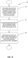
- Figure 9 shows the torque-displacement curve 120 for the decoupler 20, when the torque at any instant is less than the threshold acceleration. As can be seen, there is no slippage that occurs - the torque-displacement curve is similar to that of other decoupling devices.
- Figure 10 illustrates a method 150 of controlling torque to an accessory (e.g. the alternator 16a) in an accessory drive on an engine (e.g. engine 10).
- the method includes a step 152 of providing a decoupler (such as the decoupler 20) including a decoupler input member (e.g. the pulley 24) and a decoupler output member (e.g. the shaft adapter 22).
- a decoupler such as the decoupler 20
- the decoupler further includes a wrap spring clutch (e.g. wrap spring clutch 32) and an isolation spring (e.g. isolation spring 28) that act in series in a torque path between the decoupler input member and the decoupler output member.
- the wrap spring clutch has a radially inner surface and a radially outer surface. One of the radially inner and outer surfaces engages the clutch engagement surface. A volume of lubricant is provided, and, in a first state of the decoupler, is positioned between said one of the radially inner and outer surfaces and the clutch engagement surface to lubricate the wrap spring clutch and the clutch engagement surface.
- Step 154 includes, while the decoupler is in the first state and the engine is on, accelerating the decoupler input member at an acceleration that is beyond a threshold acceleration, during which the volume of lubricant generates slippage between said one of the radially inner and outer surfaces and the clutch engagement surface for a period of time that is greater than a selected period of time, wherein, after the first period of time, said one of the radially inner and outer surfaces engages the clutch engagement surface without slippage.
- Step 156 includes, while the decoupler is in the first state and the engine is off, turning the engine on and accelerating the decoupler input member at a startup acceleration that is beyond the threshold acceleration, but for a period of time that is less than the selected period of time, such that there is slippage throughout when the decoupler input member is accelerated at the startup acceleration.
- the wrap spring clutch 32 is formed from a wire that has an axial dimension DA that is greater than a radial dimension DR.
- DA axial dimension
- DR radial dimension
- the lubricant 70 could be other types of grease. It is theorized that a grease having a relatively low viscosity is preferred.
Landscapes
- Engineering & Computer Science (AREA)
- General Engineering & Computer Science (AREA)
- Mechanical Engineering (AREA)
- Chemical & Material Sciences (AREA)
- Combustion & Propulsion (AREA)
- Transportation (AREA)
- Mechanical Operated Clutches (AREA)
- Pulleys (AREA)
Claims (5)
- Entkoppler (20) für einen Hilfsantrieb für einen Motor (10), umfassend:ein Entkoppler-Eingangselement (24) und ein Entkoppler-Ausgangselement (22), wobei entweder das Entkoppler-Eingangselement (24) oder das Entkoppler-Ausgangselement (22) eine Kupplungseingriffsfläche (43) aufweist;eine Schlingfederkupplung (32) und eine Isolationsfeder (28), die in Reihe in einem Drehmomentpfad zwischen dem Entkoppler-Eingangselement (24) und dem Entkoppler-Ausgangselement (22) wirken, wobei die Schlingfederkupplung (32) eine radial innere Oberfläche (69) und eine radial äußere Oberfläche (67) aufweist, wobei eine der radial inneren und äußeren Oberflächen (69, 67) mit der Kupplungseingriffsfläche (43) in einem Interferenzsitz mit der Kupplungseingriffsfläche in Eingriff steht; undein Schmiermittelvolumen (70), das in einem ersten Zustand des Entkopplers (20) zwischen der einen der radial inneren und äußeren Flächen (69, 67) und der Kupplungseingriffsfläche (43) angeordnet ist, um die Schlingfederkupplung (32) und die Kupplungseingriffsfläche (43) zu schmieren,wobei das Ausmaß der Interferenz und das Schmiermittel so gewählt sind, dass, wenn sich der Entkoppler im ersten Zustand befindet und das Entkoppler-Eingangselement mit einer Beschleunigung beschleunigt wird, die über einer Schwellenbeschleunigung liegt, das Schmiermittelvolumen für eine ausgewählte Zeitdauer einen Schlupf zwischen der einen der radial inneren und äußeren Oberflächen (69, 67) und der Kupplungseingriffsfläche (43) erzeugt,wobei nach der ausgewählten Zeitdauer die eine der radial inneren und äußeren Oberflächen (69, 67) die Kupplungseingriffsfläche (43) ohne Schlupf in Eingriff nimmt;wobei, wenn der Entkoppler mit einem Motor verbunden ist, sich der Entkoppler in dem ersten Zustand befindet, wenn der Motor ausgeschaltet ist, und wobei, wenn der Motor eingeschaltet ist, das Entkoppler-Eingangselement mit einer Anfahrbeschleunigung beschleunigt wird, die über der Schwellenbeschleunigung liegt, jedoch für eine Zeitdauer, die geringer ist als die ausgewählte Zeitdauer, so dass durchgehend Schlupf vorhanden ist, wenn das Entkoppler-Eingangselement mit der Anfahrbeschleunigung beschleunigt wird, wobei die Isolationsfeder (28) eine schraubenförmige Torsionsfeder ist, die von der Schlingfederkupplung (32) durch eine Hülse (57) radial beabstandet ist, wobei die Schlingfederkupplung (32) ein Federeingriffsende (60), das in einem Träger (30) gehalten wird, und ein freies Ende (64) aufweist, wobei das freie Ende (64) so positioniert ist, dass es ein Drehmoment mit der Kupplungseingriffsfläche während der Beschleunigung des Entkoppler-Eingangselements (24) relativ zu dem Entkoppler-Ausgangselement überträgt,und wobei die Isolationsfeder ein erstes Ende und ein zweites Ende (49, 52) hat, wobei das zweite Ende (52) in dem Träger (30) positioniert ist, um ein Drehmoment mit dem Federeingriffsende (60) der Schlingfederkupplung (32) zu übertragen, und das erste Ende (49) positioniert ist, um ein Drehmoment mit dem anderen des Entkoppler-Eingangselements (24) und des Entkoppler-Ausgangselements (22) zu übertragen,wobei das erste Ende (49) der Isolationsfeder (28) axial neben dem freien Ende (64) der Schlingfederkupplung (32) angeordnet ist,wobei während der Beschleunigung des Entkoppler-Eingangselements (24) relativ zu dem Entkoppler-Ausgangselement (22) eine Relativbewegung des freien Endes (64) der Schlingfederkupplung (32) relativ zu dem Träger in einer ersten Drehrichtung (91) stattfindet und eine Relativbewegung des zweiten Endes (52) der Isolationsfeder (28) relativ zu dem Träger in einer zweiten Drehrichtung (D2) stattfindet,und wobei während einer Beschleunigung des Entkoppler-Eingangselements (24) relativ zu dem Entkoppler-Ausgangselement (22), die größer als die Schwellenbeschleunigung ist, eine radiale Bewegung des ersten Endes (49) der Isolationsfeder eine radiale Bewegung der Hülse (57) antreibt, um so mit dem freien Ende der Schlingfederkupplung reibschlüssig in Eingriff zu kommen, um einen Widerstand gegen eine Drehbewegung des freien Endes der Schlingfederkupplung in der ersten Drehrichtung relativ zu dem Träger zu bewirken, wobei die Schlingfederkupplung (32) aus einem Draht mit einer Querschnittsform mit einer radialen Abmessung und einer axialen Abmessung, die größer als die radiale Abmessung ist, hergestellt ist.
- Entkoppler nach Anspruch 1, wobei die eine der radial inneren und äußeren Oberflächen (69, 67) die radial äußere Oberfläche (67) ist und die Kupplungseingriffsfläche (43) eine radial innere Oberfläche des Entkoppler-Eingangselements ist.
- Entkoppler nach Anspruch 2, wobei das Entkoppler-Eingangselement eine Riemenscheibe ist und das Entkoppler-Ausgangselement ein Wellenadapter ist, der zur Montage an einem Zubehörteil für den Motor konfiguriert ist.
- Entkoppler nach Anspruch 1, wobei das Entkoppler-Eingangselement eine Riemenscheibe ist und das Entkoppler-Ausgangselement ein Wellenadapter ist, der für die Montage an einer Lichtmaschine für den Motor konfiguriert ist.
- Verfahren zum Steuern des Drehmoments an einem Zubehörteil (16) in einem Hilfsantrieb an einem Motor (10), umfassend:a) Bereitstellen eines Entkopplers (20) mit einem Entkoppler-Eingangselement (22) und einem Entkoppler-Ausgangselement (24), wobei entweder das Entkoppler-Eingangselement (22) oder das Entkoppler-Ausgangselement (24) eine Kupplungseingriffsfläche (43) aufweist, und ferner mit einer Schlingfederkupplung (32) und einer Isolationsfeder (28), die in einem Drehmomentweg zwischen dem Entkoppler-Eingangselement (22) und dem Entkoppler-Ausgangselement (24) in Reihe wirken, wobei die Schlingfederkupplung (32) eine radial innere Oberfläche (69) und eine radial äußere Oberfläche (67) aufweist, wobei eine der radial inneren und äußeren Oberflächen (69, 67) mit der Kupplungseingriffsfläche (43) in Eingriff steht, und ferner ein Schmiermittelvolumen (70) enthält, das in einem ersten Zustand des Entkopplers (20) zwischen der einen der radial inneren und äußeren Oberflächen (69, 67) und der Kupplungseingriffsfläche (43) angeordnet ist, um die Schlingfederkupplung und die Kupplungseingriffsfläche zu schmieren;b) während sich der Entkoppler (20) im ersten Zustand befindet und der Motor (10) eingeschaltet ist, Beschleunigen des Entkoppler-Eingangselements (22) mit einer Beschleunigung, die jenseits einer Schwellenbeschleunigung liegt, während der das Schmiermittelvolumen Schlupf zwischen der radial inneren oder der radial äußeren Oberfläche (69, 67) und der Kupplungseingriffsfläche (43) für eine ausgewählte Zeitdauer erzeugt, und dann während einer fortgesetzten Beschleunigung über die Schwellenbeschleunigung hinaus nach der ersten Zeitdauer die eine der radial inneren und äußeren Oberflächen mit der Kupplungseingriffsfläche (43) ohne Schlupf in Eingriff kommt; undc) während sich der Entkoppler (20) im ersten Zustand befindet und der Motor abgestellt ist, den Motor einschalten und das Entkoppler-Eingangselement (22) mit einer Anfahrbeschleunigung beschleunigen, die über der Schwellenbeschleunigung liegt, jedoch für eine Zeitdauer, die kürzer als die ausgewählte Zeitdauer ist, so dass durchgehend Schlupf auftritt, wenn das Entkoppler-Eingangselement (22) mit der Anfahrbeschleunigung beschleunigt wird.
Applications Claiming Priority (3)
| Application Number | Priority Date | Filing Date | Title |
|---|---|---|---|
| US201962823662P | 2019-03-26 | 2019-03-26 | |
| US201962930255P | 2019-11-04 | 2019-11-04 | |
| PCT/CA2020/050398 WO2020191495A1 (en) | 2019-03-26 | 2020-03-26 | Rotary device with clutch with time-based slip and method of providing time-based slip for a rotary device |
Publications (3)
| Publication Number | Publication Date |
|---|---|
| EP3948002A1 EP3948002A1 (de) | 2022-02-09 |
| EP3948002A4 EP3948002A4 (de) | 2022-12-21 |
| EP3948002B1 true EP3948002B1 (de) | 2024-04-03 |
Family
ID=72608405
Family Applications (1)
| Application Number | Title | Priority Date | Filing Date |
|---|---|---|---|
| EP20777522.2A Active EP3948002B1 (de) | 2019-03-26 | 2020-03-26 | Rotationsvorrichtung mit kupplung mit zeitbasiertem schlupf und verfahren zur bereitstellung von zeitbasiertem schlupf für eine rotationsvorrichtung |
Country Status (4)
| Country | Link |
|---|---|
| US (1) | US12005779B2 (de) |
| EP (1) | EP3948002B1 (de) |
| CN (1) | CN113474570B (de) |
| WO (1) | WO2020191495A1 (de) |
Families Citing this family (1)
| Publication number | Priority date | Publication date | Assignee | Title |
|---|---|---|---|---|
| IT202000030395A1 (it) * | 2020-12-10 | 2022-06-10 | Dayco Europe Srl | Puleggia filtrante migliorata |
Family Cites Families (51)
| Publication number | Priority date | Publication date | Assignee | Title |
|---|---|---|---|---|
| US2899193A (en) | 1959-08-11 | Low gradient spring motor | ||
| US2559400A (en) | 1945-01-08 | 1951-07-03 | Eaton Mfg Co | Spring testing machine |
| US2761547A (en) | 1954-10-22 | 1956-09-04 | Fortuna Werke Spezialmaschinen | Rollers |
| US3047280A (en) | 1959-02-25 | 1962-07-31 | Ametek Inc | Spring motor |
| US3602205A (en) | 1969-05-13 | 1971-08-31 | Eaton Yale & Towne | Dual beam valve spring |
| US3618730A (en) | 1969-12-12 | 1971-11-09 | Vari Typer Corp | Torque-limiting clutch |
| US4750087A (en) | 1984-03-26 | 1988-06-07 | The Boeing Company | Ventilated instrument panel support rail |
| CN85102855B (zh) | 1985-04-01 | 1987-09-23 | 曹培生 | 一种非线性电磁振动装置 |
| US4750871A (en) | 1987-03-10 | 1988-06-14 | Mechanical Technology Incorporated | Stabilizing means for free piston-type linear resonant reciprocating machines |
| US5139463A (en) | 1991-06-05 | 1992-08-18 | Litens Automotive Partnership | Serpentine drive with coil spring alternator connection |
| DE4426666A1 (de) | 1994-07-28 | 1996-02-01 | Schaeffler Waelzlager Kg | Einrichtung zur Dämpfung von Federschwingungen |
| JPH09117721A (ja) | 1994-09-28 | 1997-05-06 | Seiko Instr Inc | 振動モジュール |
| GB9420741D0 (en) | 1994-10-14 | 1994-11-30 | Litens Automotive Inc | Crankshaft decoupler |
| US5722909A (en) * | 1995-09-27 | 1998-03-03 | Litens Automotive Partnership | Series type decoupling device |
| US5749449A (en) | 1996-12-16 | 1998-05-12 | Sikorsky Aircraft Corporation | Coil spring for overrunning spring clutches |
| JP4535517B2 (ja) | 1997-05-07 | 2010-09-01 | ライテンズ オートモーティブ パートナーシップ | 改良したオーバーラン・オルタネータ・デカプラーを備えるサーペンタインベルト駆動システム |
| US6047811A (en) | 1997-08-21 | 2000-04-11 | David R. Zittel | Method and vibratory conveyor |
| US6161512A (en) | 1998-09-17 | 2000-12-19 | Morse Tec Europe S.P.A. | Sprocket system with internal torsional damper |
| US7191880B2 (en) | 2000-05-31 | 2007-03-20 | Ntn Corporation | Over-running clutch pulley with increased surface microhardness |
| US6394248B1 (en) | 2000-05-31 | 2002-05-28 | Ntn Corporation | Compression spring complaint one-way over-running clutch pulley |
| JP2002227973A (ja) | 2001-02-05 | 2002-08-14 | Ntn Corp | スプリングクラッチ |
| US6710489B1 (en) | 2001-08-30 | 2004-03-23 | Indigo Energy, Inc. | Axially free flywheel system |
| JP2003278790A (ja) | 2002-03-20 | 2003-10-02 | Suncall Corp | 摩擦式回転運動伝達装置 |
| US7153227B2 (en) * | 2002-04-18 | 2006-12-26 | Litens Automotive | Isolator for alternator pulley |
| RU2005102818A (ru) | 2002-07-26 | 2005-08-10 | Литенс Аутомотив (Ca) | Расщепляющий узел для передачи вращающего момента |
| CA2759773C (en) | 2002-11-22 | 2013-05-28 | Litens Automotive | Flexible coupling with misalignment compensation |
| PL210159B1 (pl) * | 2003-02-04 | 2011-12-30 | Litens Automotive | Mechanizm odprzęgania |
| BRPI0414587A (pt) | 2003-09-22 | 2006-11-07 | Litens Automotive Inc | conjunto desacoplador para transferir torque de rotação entre um eixo de acionamento e um elemento de acionamento sem-fim de um motor automotivo |
| BRPI0417395B1 (pt) | 2003-12-09 | 2016-06-07 | Litens Automotive Inc | conjunto desacoplador para transferir torque entre um eixo motor e um elemento de transmissão sem fim de um motor automotivo |
| JP4549098B2 (ja) | 2004-05-10 | 2010-09-22 | Ntn株式会社 | ばねクラッチ |
| US7318776B2 (en) | 2004-05-24 | 2008-01-15 | Ntn Corporation | Torque limiter |
| FR2878305B1 (fr) | 2004-11-24 | 2008-05-30 | Hutchinson Sa | Poulie d'organe de transmission de puissance, alterno-demarreur separe equipe d'une telle poulie et systeme d'entrainement de moteur thermique |
| JP5057997B2 (ja) | 2005-02-03 | 2012-10-24 | ライテンズ オートモーティブ パートナーシップ | デカップラアセンブリ |
| JP2009500571A (ja) | 2005-07-05 | 2009-01-08 | ライテンズ オートモーティブ パートナーシップ | ロック機構を有するオーバーランニング・デカップラー |
| FR2891039B1 (fr) | 2005-09-19 | 2009-05-22 | Hutchinson Sa | Poulie de transmission de puissance |
| JP5008928B2 (ja) | 2005-10-31 | 2012-08-22 | 三ツ星ベルト株式会社 | プーリ構造体 |
| US7878315B2 (en) | 2006-04-14 | 2011-02-01 | Ntn Corporation | Spring clutch |
| EP2010792B1 (de) | 2006-04-26 | 2015-03-25 | Litens Automotive Partnership | Einrichtungsisolator für vorrichtungen mit hohem drehmoment |
| DE112007002873A5 (de) | 2006-12-11 | 2009-10-08 | Luk Lamellen Und Kupplungsbau Beteiligungs Kg | Decoupler-Anordnung |
| US8888619B2 (en) | 2008-10-27 | 2014-11-18 | Litens Automotive Partnership | Over-running decoupler with torque limiter |
| US8485331B2 (en) * | 2008-11-17 | 2013-07-16 | Litens Automotive Partnership | Driven accessory with low-power clutch for activating or de-activating same |
| CN102985716B (zh) * | 2010-06-25 | 2016-08-10 | 利滕斯汽车合伙公司 | 超速解耦器 |
| CA2829076A1 (en) * | 2010-06-25 | 2011-12-29 | Litens Automotive Partnership | Isolation pulley with overrunning and vibration damping capabilities |
| US8813928B2 (en) * | 2011-10-14 | 2014-08-26 | The Gates Corporation | Alternator isolating decoupler |
| WO2014022912A1 (en) * | 2012-08-07 | 2014-02-13 | Litens Automotive Partnership | Decoupler carrier with balanced forces |
| US9140319B2 (en) | 2012-11-20 | 2015-09-22 | Litens Automotive Partnership | Decoupler with concentric clutching members |
| EP3036450A4 (de) * | 2013-08-19 | 2017-04-26 | Litens Automotive Partnership | Entkopplerkupplungseingrifffläche mit ausgewählter oberflächenbeschichtung |
| US9033832B1 (en) * | 2014-01-23 | 2015-05-19 | Gates Corporation | Isolating decoupler |
| US9206892B2 (en) * | 2014-04-08 | 2015-12-08 | Gates Corporation | Isolating decoupler |
| US10024415B2 (en) * | 2015-11-02 | 2018-07-17 | Gates Corporation | Isolating decoupler |
| US10520039B2 (en) * | 2017-08-28 | 2019-12-31 | Gates Corporation | Isolating decoupler |
-
2020
- 2020-03-26 US US17/593,289 patent/US12005779B2/en active Active
- 2020-03-26 WO PCT/CA2020/050398 patent/WO2020191495A1/en not_active Ceased
- 2020-03-26 EP EP20777522.2A patent/EP3948002B1/de active Active
- 2020-03-26 CN CN202080016765.8A patent/CN113474570B/zh active Active
Also Published As
| Publication number | Publication date |
|---|---|
| EP3948002A4 (de) | 2022-12-21 |
| CN113474570B (zh) | 2024-08-30 |
| US20220194225A1 (en) | 2022-06-23 |
| US12005779B2 (en) | 2024-06-11 |
| WO2020191495A1 (en) | 2020-10-01 |
| CN113474570A (zh) | 2021-10-01 |
| EP3948002A1 (de) | 2022-02-09 |
Similar Documents
| Publication | Publication Date | Title |
|---|---|---|
| CN102203450B (zh) | 具有转矩限制器的超越解耦器 | |
| US7070033B2 (en) | Flexible coupling with misalignment compensation | |
| US8132657B2 (en) | Torque limited decoupler | |
| JP5945630B2 (ja) | アイソレータ・デカップラ | |
| EP1692409B1 (de) | Federhubbegrenzer für überlaufentkoppler | |
| EP2715171B1 (de) | Isolatorentkoppler | |
| EP2823192B1 (de) | Isolatorentkoppler mit drehmomentbegrenzer | |
| CN107532653B (zh) | 隔离断开器 | |
| KR20050039832A (ko) | 베어 와이어 스프링 및 그리스 윤활제를 갖는 오버러닝교류기 디커플러 풀리 | |
| US20100116617A1 (en) | Isolator with one-way clutch | |
| JP6906514B2 (ja) | アイソレーティング・デカップラ | |
| CN103221704A (zh) | 具有限定的超越能力的去耦器组件 | |
| EP3948002B1 (de) | Rotationsvorrichtung mit kupplung mit zeitbasiertem schlupf und verfahren zur bereitstellung von zeitbasiertem schlupf für eine rotationsvorrichtung | |
| JP2021169831A (ja) | 動力伝達装置 | |
| CN118749047A (zh) | 具有扭矩限制特征以保护其部件的解耦器 |
Legal Events
| Date | Code | Title | Description |
|---|---|---|---|
| STAA | Information on the status of an ep patent application or granted ep patent |
Free format text: STATUS: THE INTERNATIONAL PUBLICATION HAS BEEN MADE |
|
| PUAI | Public reference made under article 153(3) epc to a published international application that has entered the european phase |
Free format text: ORIGINAL CODE: 0009012 |
|
| STAA | Information on the status of an ep patent application or granted ep patent |
Free format text: STATUS: REQUEST FOR EXAMINATION WAS MADE |
|
| 17P | Request for examination filed |
Effective date: 20210913 |
|
| AK | Designated contracting states |
Kind code of ref document: A1 Designated state(s): AL AT BE BG CH CY CZ DE DK EE ES FI FR GB GR HR HU IE IS IT LI LT LU LV MC MK MT NL NO PL PT RO RS SE SI SK SM TR |
|
| DAV | Request for validation of the european patent (deleted) | ||
| DAX | Request for extension of the european patent (deleted) | ||
| A4 | Supplementary search report drawn up and despatched |
Effective date: 20221118 |
|
| RIC1 | Information provided on ipc code assigned before grant |
Ipc: F16D 41/20 20060101ALI20221114BHEP Ipc: F16H 7/20 20060101ALI20221114BHEP Ipc: F16D 43/02 20060101ALI20221114BHEP Ipc: F16D 3/14 20060101ALI20221114BHEP Ipc: F16D 13/12 20060101ALI20221114BHEP Ipc: F02B 67/06 20060101ALI20221114BHEP Ipc: B60K 25/02 20060101ALI20221114BHEP Ipc: F16D 7/02 20060101AFI20221114BHEP |
|
| RIC1 | Information provided on ipc code assigned before grant |
Ipc: F16D 41/20 20060101ALI20230901BHEP Ipc: F16H 7/20 20060101ALI20230901BHEP Ipc: F16D 43/02 20060101ALI20230901BHEP Ipc: F16D 3/14 20060101ALI20230901BHEP Ipc: F16D 13/12 20060101ALI20230901BHEP Ipc: F02B 67/06 20060101ALI20230901BHEP Ipc: B60K 25/02 20060101ALI20230901BHEP Ipc: F16D 7/02 20060101AFI20230901BHEP |
|
| GRAP | Despatch of communication of intention to grant a patent |
Free format text: ORIGINAL CODE: EPIDOSNIGR1 |
|
| STAA | Information on the status of an ep patent application or granted ep patent |
Free format text: STATUS: GRANT OF PATENT IS INTENDED |
|
| INTG | Intention to grant announced |
Effective date: 20231121 |
|
| GRAS | Grant fee paid |
Free format text: ORIGINAL CODE: EPIDOSNIGR3 |
|
| GRAA | (expected) grant |
Free format text: ORIGINAL CODE: 0009210 |
|
| STAA | Information on the status of an ep patent application or granted ep patent |
Free format text: STATUS: THE PATENT HAS BEEN GRANTED |
|
| P01 | Opt-out of the competence of the unified patent court (upc) registered |
Effective date: 20240130 |
|
| AK | Designated contracting states |
Kind code of ref document: B1 Designated state(s): AL AT BE BG CH CY CZ DE DK EE ES FI FR GB GR HR HU IE IS IT LI LT LU LV MC MK MT NL NO PL PT RO RS SE SI SK SM TR |
|
| REG | Reference to a national code |
Ref country code: CH Ref legal event code: EP |
|
| REG | Reference to a national code |
Ref country code: DE Ref legal event code: R096 Ref document number: 602020028421 Country of ref document: DE |
|
| REG | Reference to a national code |
Ref country code: IE Ref legal event code: FG4D |
|
| REG | Reference to a national code |
Ref country code: LT Ref legal event code: MG9D |
|
| REG | Reference to a national code |
Ref country code: NL Ref legal event code: MP Effective date: 20240403 |
|
| REG | Reference to a national code |
Ref country code: AT Ref legal event code: MK05 Ref document number: 1672627 Country of ref document: AT Kind code of ref document: T Effective date: 20240403 |
|
| PG25 | Lapsed in a contracting state [announced via postgrant information from national office to epo] |
Ref country code: NL Free format text: LAPSE BECAUSE OF FAILURE TO SUBMIT A TRANSLATION OF THE DESCRIPTION OR TO PAY THE FEE WITHIN THE PRESCRIBED TIME-LIMIT Effective date: 20240403 |
|
| PG25 | Lapsed in a contracting state [announced via postgrant information from national office to epo] |
Ref country code: NL Free format text: LAPSE BECAUSE OF FAILURE TO SUBMIT A TRANSLATION OF THE DESCRIPTION OR TO PAY THE FEE WITHIN THE PRESCRIBED TIME-LIMIT Effective date: 20240403 |
|
| PG25 | Lapsed in a contracting state [announced via postgrant information from national office to epo] |
Ref country code: IS Free format text: LAPSE BECAUSE OF FAILURE TO SUBMIT A TRANSLATION OF THE DESCRIPTION OR TO PAY THE FEE WITHIN THE PRESCRIBED TIME-LIMIT Effective date: 20240803 |
|
| PG25 | Lapsed in a contracting state [announced via postgrant information from national office to epo] |
Ref country code: BG Free format text: LAPSE BECAUSE OF FAILURE TO SUBMIT A TRANSLATION OF THE DESCRIPTION OR TO PAY THE FEE WITHIN THE PRESCRIBED TIME-LIMIT Effective date: 20240403 |
|
| PG25 | Lapsed in a contracting state [announced via postgrant information from national office to epo] |
Ref country code: HR Free format text: LAPSE BECAUSE OF FAILURE TO SUBMIT A TRANSLATION OF THE DESCRIPTION OR TO PAY THE FEE WITHIN THE PRESCRIBED TIME-LIMIT Effective date: 20240403 Ref country code: FI Free format text: LAPSE BECAUSE OF FAILURE TO SUBMIT A TRANSLATION OF THE DESCRIPTION OR TO PAY THE FEE WITHIN THE PRESCRIBED TIME-LIMIT Effective date: 20240403 |
|
| PG25 | Lapsed in a contracting state [announced via postgrant information from national office to epo] |
Ref country code: GR Free format text: LAPSE BECAUSE OF FAILURE TO SUBMIT A TRANSLATION OF THE DESCRIPTION OR TO PAY THE FEE WITHIN THE PRESCRIBED TIME-LIMIT Effective date: 20240704 |
|
| PG25 | Lapsed in a contracting state [announced via postgrant information from national office to epo] |
Ref country code: PT Free format text: LAPSE BECAUSE OF FAILURE TO SUBMIT A TRANSLATION OF THE DESCRIPTION OR TO PAY THE FEE WITHIN THE PRESCRIBED TIME-LIMIT Effective date: 20240805 |
|
| PG25 | Lapsed in a contracting state [announced via postgrant information from national office to epo] |
Ref country code: ES Free format text: LAPSE BECAUSE OF FAILURE TO SUBMIT A TRANSLATION OF THE DESCRIPTION OR TO PAY THE FEE WITHIN THE PRESCRIBED TIME-LIMIT Effective date: 20240403 |
|
| PG25 | Lapsed in a contracting state [announced via postgrant information from national office to epo] |
Ref country code: CZ Free format text: LAPSE BECAUSE OF FAILURE TO SUBMIT A TRANSLATION OF THE DESCRIPTION OR TO PAY THE FEE WITHIN THE PRESCRIBED TIME-LIMIT Effective date: 20240403 |
|
| PG25 | Lapsed in a contracting state [announced via postgrant information from national office to epo] |
Ref country code: AT Free format text: LAPSE BECAUSE OF FAILURE TO SUBMIT A TRANSLATION OF THE DESCRIPTION OR TO PAY THE FEE WITHIN THE PRESCRIBED TIME-LIMIT Effective date: 20240403 |
|
| PG25 | Lapsed in a contracting state [announced via postgrant information from national office to epo] |
Ref country code: PL Free format text: LAPSE BECAUSE OF FAILURE TO SUBMIT A TRANSLATION OF THE DESCRIPTION OR TO PAY THE FEE WITHIN THE PRESCRIBED TIME-LIMIT Effective date: 20240403 |
|
| PG25 | Lapsed in a contracting state [announced via postgrant information from national office to epo] |
Ref country code: LV Free format text: LAPSE BECAUSE OF FAILURE TO SUBMIT A TRANSLATION OF THE DESCRIPTION OR TO PAY THE FEE WITHIN THE PRESCRIBED TIME-LIMIT Effective date: 20240403 |
|
| PG25 | Lapsed in a contracting state [announced via postgrant information from national office to epo] |
Ref country code: PT Free format text: LAPSE BECAUSE OF FAILURE TO SUBMIT A TRANSLATION OF THE DESCRIPTION OR TO PAY THE FEE WITHIN THE PRESCRIBED TIME-LIMIT Effective date: 20240805 Ref country code: PL Free format text: LAPSE BECAUSE OF FAILURE TO SUBMIT A TRANSLATION OF THE DESCRIPTION OR TO PAY THE FEE WITHIN THE PRESCRIBED TIME-LIMIT Effective date: 20240403 Ref country code: NO Free format text: LAPSE BECAUSE OF FAILURE TO SUBMIT A TRANSLATION OF THE DESCRIPTION OR TO PAY THE FEE WITHIN THE PRESCRIBED TIME-LIMIT Effective date: 20240703 Ref country code: LV Free format text: LAPSE BECAUSE OF FAILURE TO SUBMIT A TRANSLATION OF THE DESCRIPTION OR TO PAY THE FEE WITHIN THE PRESCRIBED TIME-LIMIT Effective date: 20240403 Ref country code: IS Free format text: LAPSE BECAUSE OF FAILURE TO SUBMIT A TRANSLATION OF THE DESCRIPTION OR TO PAY THE FEE WITHIN THE PRESCRIBED TIME-LIMIT Effective date: 20240803 Ref country code: HR Free format text: LAPSE BECAUSE OF FAILURE TO SUBMIT A TRANSLATION OF THE DESCRIPTION OR TO PAY THE FEE WITHIN THE PRESCRIBED TIME-LIMIT Effective date: 20240403 Ref country code: GR Free format text: LAPSE BECAUSE OF FAILURE TO SUBMIT A TRANSLATION OF THE DESCRIPTION OR TO PAY THE FEE WITHIN THE PRESCRIBED TIME-LIMIT Effective date: 20240704 Ref country code: FI Free format text: LAPSE BECAUSE OF FAILURE TO SUBMIT A TRANSLATION OF THE DESCRIPTION OR TO PAY THE FEE WITHIN THE PRESCRIBED TIME-LIMIT Effective date: 20240403 Ref country code: ES Free format text: LAPSE BECAUSE OF FAILURE TO SUBMIT A TRANSLATION OF THE DESCRIPTION OR TO PAY THE FEE WITHIN THE PRESCRIBED TIME-LIMIT Effective date: 20240403 Ref country code: CZ Free format text: LAPSE BECAUSE OF FAILURE TO SUBMIT A TRANSLATION OF THE DESCRIPTION OR TO PAY THE FEE WITHIN THE PRESCRIBED TIME-LIMIT Effective date: 20240403 Ref country code: BG Free format text: LAPSE BECAUSE OF FAILURE TO SUBMIT A TRANSLATION OF THE DESCRIPTION OR TO PAY THE FEE WITHIN THE PRESCRIBED TIME-LIMIT Effective date: 20240403 Ref country code: AT Free format text: LAPSE BECAUSE OF FAILURE TO SUBMIT A TRANSLATION OF THE DESCRIPTION OR TO PAY THE FEE WITHIN THE PRESCRIBED TIME-LIMIT Effective date: 20240403 Ref country code: RS Free format text: LAPSE BECAUSE OF FAILURE TO SUBMIT A TRANSLATION OF THE DESCRIPTION OR TO PAY THE FEE WITHIN THE PRESCRIBED TIME-LIMIT Effective date: 20240703 |
|
| REG | Reference to a national code |
Ref country code: DE Ref legal event code: R097 Ref document number: 602020028421 Country of ref document: DE |
|
| PG25 | Lapsed in a contracting state [announced via postgrant information from national office to epo] |
Ref country code: DK Free format text: LAPSE BECAUSE OF FAILURE TO SUBMIT A TRANSLATION OF THE DESCRIPTION OR TO PAY THE FEE WITHIN THE PRESCRIBED TIME-LIMIT Effective date: 20240403 |
|
| PG25 | Lapsed in a contracting state [announced via postgrant information from national office to epo] |
Ref country code: EE Free format text: LAPSE BECAUSE OF FAILURE TO SUBMIT A TRANSLATION OF THE DESCRIPTION OR TO PAY THE FEE WITHIN THE PRESCRIBED TIME-LIMIT Effective date: 20240403 |
|
| PG25 | Lapsed in a contracting state [announced via postgrant information from national office to epo] |
Ref country code: SK Free format text: LAPSE BECAUSE OF FAILURE TO SUBMIT A TRANSLATION OF THE DESCRIPTION OR TO PAY THE FEE WITHIN THE PRESCRIBED TIME-LIMIT Effective date: 20240403 Ref country code: RO Free format text: LAPSE BECAUSE OF FAILURE TO SUBMIT A TRANSLATION OF THE DESCRIPTION OR TO PAY THE FEE WITHIN THE PRESCRIBED TIME-LIMIT Effective date: 20240403 |
|
| PG25 | Lapsed in a contracting state [announced via postgrant information from national office to epo] |
Ref country code: SM Free format text: LAPSE BECAUSE OF FAILURE TO SUBMIT A TRANSLATION OF THE DESCRIPTION OR TO PAY THE FEE WITHIN THE PRESCRIBED TIME-LIMIT Effective date: 20240403 |
|
| PG25 | Lapsed in a contracting state [announced via postgrant information from national office to epo] |
Ref country code: SM Free format text: LAPSE BECAUSE OF FAILURE TO SUBMIT A TRANSLATION OF THE DESCRIPTION OR TO PAY THE FEE WITHIN THE PRESCRIBED TIME-LIMIT Effective date: 20240403 Ref country code: SK Free format text: LAPSE BECAUSE OF FAILURE TO SUBMIT A TRANSLATION OF THE DESCRIPTION OR TO PAY THE FEE WITHIN THE PRESCRIBED TIME-LIMIT Effective date: 20240403 Ref country code: RO Free format text: LAPSE BECAUSE OF FAILURE TO SUBMIT A TRANSLATION OF THE DESCRIPTION OR TO PAY THE FEE WITHIN THE PRESCRIBED TIME-LIMIT Effective date: 20240403 Ref country code: EE Free format text: LAPSE BECAUSE OF FAILURE TO SUBMIT A TRANSLATION OF THE DESCRIPTION OR TO PAY THE FEE WITHIN THE PRESCRIBED TIME-LIMIT Effective date: 20240403 Ref country code: DK Free format text: LAPSE BECAUSE OF FAILURE TO SUBMIT A TRANSLATION OF THE DESCRIPTION OR TO PAY THE FEE WITHIN THE PRESCRIBED TIME-LIMIT Effective date: 20240403 |
|
| PLBE | No opposition filed within time limit |
Free format text: ORIGINAL CODE: 0009261 |
|
| STAA | Information on the status of an ep patent application or granted ep patent |
Free format text: STATUS: NO OPPOSITION FILED WITHIN TIME LIMIT |
|
| 26N | No opposition filed |
Effective date: 20250106 |
|
| PG25 | Lapsed in a contracting state [announced via postgrant information from national office to epo] |
Ref country code: SI Free format text: LAPSE BECAUSE OF FAILURE TO SUBMIT A TRANSLATION OF THE DESCRIPTION OR TO PAY THE FEE WITHIN THE PRESCRIBED TIME-LIMIT Effective date: 20240403 |
|
| PG25 | Lapsed in a contracting state [announced via postgrant information from national office to epo] |
Ref country code: SE Free format text: LAPSE BECAUSE OF FAILURE TO SUBMIT A TRANSLATION OF THE DESCRIPTION OR TO PAY THE FEE WITHIN THE PRESCRIBED TIME-LIMIT Effective date: 20240403 |
|
| PG25 | Lapsed in a contracting state [announced via postgrant information from national office to epo] |
Ref country code: MC Free format text: LAPSE BECAUSE OF FAILURE TO SUBMIT A TRANSLATION OF THE DESCRIPTION OR TO PAY THE FEE WITHIN THE PRESCRIBED TIME-LIMIT Effective date: 20240403 |
|
| REG | Reference to a national code |
Ref country code: CH Ref legal event code: H13 Free format text: ST27 STATUS EVENT CODE: U-0-0-H10-H13 (AS PROVIDED BY THE NATIONAL OFFICE) Effective date: 20251024 |
|
| PG25 | Lapsed in a contracting state [announced via postgrant information from national office to epo] |
Ref country code: LU Free format text: LAPSE BECAUSE OF NON-PAYMENT OF DUE FEES Effective date: 20250326 |
|
| REG | Reference to a national code |
Ref country code: BE Ref legal event code: MM Effective date: 20250331 |
|
| PGFP | Annual fee paid to national office [announced via postgrant information from national office to epo] |
Ref country code: FR Payment date: 20251231 Year of fee payment: 7 |
|
| PG25 | Lapsed in a contracting state [announced via postgrant information from national office to epo] |
Ref country code: BE Free format text: LAPSE BECAUSE OF NON-PAYMENT OF DUE FEES Effective date: 20250331 |
|
| PG25 | Lapsed in a contracting state [announced via postgrant information from national office to epo] |
Ref country code: CH Free format text: LAPSE BECAUSE OF NON-PAYMENT OF DUE FEES Effective date: 20250331 |
|
| PG25 | Lapsed in a contracting state [announced via postgrant information from national office to epo] |
Ref country code: IE Free format text: LAPSE BECAUSE OF NON-PAYMENT OF DUE FEES Effective date: 20250326 |
|
| PG25 | Lapsed in a contracting state [announced via postgrant information from national office to epo] |
Ref country code: IT Free format text: LAPSE BECAUSE OF FAILURE TO SUBMIT A TRANSLATION OF THE DESCRIPTION OR TO PAY THE FEE WITHIN THE PRESCRIBED TIME-LIMIT Effective date: 20240403 |
|
| PGFP | Annual fee paid to national office [announced via postgrant information from national office to epo] |
Ref country code: GB Payment date: 20260106 Year of fee payment: 7 |
|
| PGFP | Annual fee paid to national office [announced via postgrant information from national office to epo] |
Ref country code: DE Payment date: 20260102 Year of fee payment: 7 |