EP3960482B1 - Élément optique anti-contrefaçon et son procédé de fabrication - Google Patents
Élément optique anti-contrefaçon et son procédé de fabrication Download PDFInfo
- Publication number
- EP3960482B1 EP3960482B1 EP20794469.5A EP20794469A EP3960482B1 EP 3960482 B1 EP3960482 B1 EP 3960482B1 EP 20794469 A EP20794469 A EP 20794469A EP 3960482 B1 EP3960482 B1 EP 3960482B1
- Authority
- EP
- European Patent Office
- Prior art keywords
- layer
- optical anti
- counterfeiting element
- alloy
- grating
- Prior art date
- Legal status (The legal status is an assumption and is not a legal conclusion. Google has not performed a legal analysis and makes no representation as to the accuracy of the status listed.)
- Active
Links
Images


Classifications
-
- B—PERFORMING OPERATIONS; TRANSPORTING
- B42—BOOKBINDING; ALBUMS; FILES; SPECIAL PRINTED MATTER
- B42D—BOOKS; BOOK COVERS; LOOSE LEAVES; PRINTED MATTER CHARACTERISED BY IDENTIFICATION OR SECURITY FEATURES; PRINTED MATTER OF SPECIAL FORMAT OR STYLE NOT OTHERWISE PROVIDED FOR; DEVICES FOR USE THEREWITH AND NOT OTHERWISE PROVIDED FOR; MOVABLE-STRIP WRITING OR READING APPARATUS
- B42D25/00—Information-bearing cards or sheet-like structures characterised by identification or security features; Manufacture thereof
- B42D25/30—Identification or security features, e.g. for preventing forgery
- B42D25/324—Reliefs
-
- B—PERFORMING OPERATIONS; TRANSPORTING
- B42—BOOKBINDING; ALBUMS; FILES; SPECIAL PRINTED MATTER
- B42D—BOOKS; BOOK COVERS; LOOSE LEAVES; PRINTED MATTER CHARACTERISED BY IDENTIFICATION OR SECURITY FEATURES; PRINTED MATTER OF SPECIAL FORMAT OR STYLE NOT OTHERWISE PROVIDED FOR; DEVICES FOR USE THEREWITH AND NOT OTHERWISE PROVIDED FOR; MOVABLE-STRIP WRITING OR READING APPARATUS
- B42D25/00—Information-bearing cards or sheet-like structures characterised by identification or security features; Manufacture thereof
- B42D25/30—Identification or security features, e.g. for preventing forgery
- B42D25/328—Diffraction gratings; Holograms
-
- B—PERFORMING OPERATIONS; TRANSPORTING
- B42—BOOKBINDING; ALBUMS; FILES; SPECIAL PRINTED MATTER
- B42D—BOOKS; BOOK COVERS; LOOSE LEAVES; PRINTED MATTER CHARACTERISED BY IDENTIFICATION OR SECURITY FEATURES; PRINTED MATTER OF SPECIAL FORMAT OR STYLE NOT OTHERWISE PROVIDED FOR; DEVICES FOR USE THEREWITH AND NOT OTHERWISE PROVIDED FOR; MOVABLE-STRIP WRITING OR READING APPARATUS
- B42D25/00—Information-bearing cards or sheet-like structures characterised by identification or security features; Manufacture thereof
- B42D25/30—Identification or security features, e.g. for preventing forgery
- B42D25/351—Translucent or partly translucent parts, e.g. windows
-
- B—PERFORMING OPERATIONS; TRANSPORTING
- B42—BOOKBINDING; ALBUMS; FILES; SPECIAL PRINTED MATTER
- B42D—BOOKS; BOOK COVERS; LOOSE LEAVES; PRINTED MATTER CHARACTERISED BY IDENTIFICATION OR SECURITY FEATURES; PRINTED MATTER OF SPECIAL FORMAT OR STYLE NOT OTHERWISE PROVIDED FOR; DEVICES FOR USE THEREWITH AND NOT OTHERWISE PROVIDED FOR; MOVABLE-STRIP WRITING OR READING APPARATUS
- B42D25/00—Information-bearing cards or sheet-like structures characterised by identification or security features; Manufacture thereof
- B42D25/30—Identification or security features, e.g. for preventing forgery
- B42D25/36—Identification or security features, e.g. for preventing forgery comprising special materials
- B42D25/373—Metallic materials
-
- B—PERFORMING OPERATIONS; TRANSPORTING
- B42—BOOKBINDING; ALBUMS; FILES; SPECIAL PRINTED MATTER
- B42D—BOOKS; BOOK COVERS; LOOSE LEAVES; PRINTED MATTER CHARACTERISED BY IDENTIFICATION OR SECURITY FEATURES; PRINTED MATTER OF SPECIAL FORMAT OR STYLE NOT OTHERWISE PROVIDED FOR; DEVICES FOR USE THEREWITH AND NOT OTHERWISE PROVIDED FOR; MOVABLE-STRIP WRITING OR READING APPARATUS
- B42D25/00—Information-bearing cards or sheet-like structures characterised by identification or security features; Manufacture thereof
- B42D25/40—Manufacture
- B42D25/405—Marking
- B42D25/415—Marking using chemicals
-
- B—PERFORMING OPERATIONS; TRANSPORTING
- B42—BOOKBINDING; ALBUMS; FILES; SPECIAL PRINTED MATTER
- B42D—BOOKS; BOOK COVERS; LOOSE LEAVES; PRINTED MATTER CHARACTERISED BY IDENTIFICATION OR SECURITY FEATURES; PRINTED MATTER OF SPECIAL FORMAT OR STYLE NOT OTHERWISE PROVIDED FOR; DEVICES FOR USE THEREWITH AND NOT OTHERWISE PROVIDED FOR; MOVABLE-STRIP WRITING OR READING APPARATUS
- B42D25/00—Information-bearing cards or sheet-like structures characterised by identification or security features; Manufacture thereof
- B42D25/40—Manufacture
- B42D25/405—Marking
- B42D25/425—Marking by deformation, e.g. embossing
-
- B—PERFORMING OPERATIONS; TRANSPORTING
- B42—BOOKBINDING; ALBUMS; FILES; SPECIAL PRINTED MATTER
- B42D—BOOKS; BOOK COVERS; LOOSE LEAVES; PRINTED MATTER CHARACTERISED BY IDENTIFICATION OR SECURITY FEATURES; PRINTED MATTER OF SPECIAL FORMAT OR STYLE NOT OTHERWISE PROVIDED FOR; DEVICES FOR USE THEREWITH AND NOT OTHERWISE PROVIDED FOR; MOVABLE-STRIP WRITING OR READING APPARATUS
- B42D25/00—Information-bearing cards or sheet-like structures characterised by identification or security features; Manufacture thereof
- B42D25/40—Manufacture
- B42D25/405—Marking
- B42D25/43—Marking by removal of material
- B42D25/445—Marking by removal of material using chemical means, e.g. etching
-
- B—PERFORMING OPERATIONS; TRANSPORTING
- B42—BOOKBINDING; ALBUMS; FILES; SPECIAL PRINTED MATTER
- B42D—BOOKS; BOOK COVERS; LOOSE LEAVES; PRINTED MATTER CHARACTERISED BY IDENTIFICATION OR SECURITY FEATURES; PRINTED MATTER OF SPECIAL FORMAT OR STYLE NOT OTHERWISE PROVIDED FOR; DEVICES FOR USE THEREWITH AND NOT OTHERWISE PROVIDED FOR; MOVABLE-STRIP WRITING OR READING APPARATUS
- B42D25/00—Information-bearing cards or sheet-like structures characterised by identification or security features; Manufacture thereof
- B42D25/40—Manufacture
- B42D25/45—Associating two or more layers
-
- G—PHYSICS
- G02—OPTICS
- G02B—OPTICAL ELEMENTS, SYSTEMS OR APPARATUS
- G02B5/00—Optical elements other than lenses
- G02B5/20—Filters
- G02B5/28—Interference filters
- G02B5/285—Interference filters comprising deposited thin solid films
- G02B5/286—Interference filters comprising deposited thin solid films having four or fewer layers, e.g. for achieving a colour effect
Definitions
- the disclosure relates to the technical field of optical anti-counterfeiting, in particular to an optical anti-counterfeiting element and a manufacturing method of the optical anti-counterfeiting element.
- the color changes of the anti-counterfeiting element may be realized through the optical principle, that is, when the optical anti-counterfeiting element is inclined, the color of the optical anti-counterfeiting element changes along with the change of a viewing angle. This color changes are very easy to identify and do not require extensive training for a user.
- Colors and color changes may be realized in various ways, for example, adopting a metal reflecting layer or coating a layer with colors on the metal reflecting layer to obtain colors, and the colors do not change with the change of the viewing angle.
- the principle of a Fabry-Perot filter may also be adopted, the structure of 'absorbing layer/dielectric layer/reflecting layer' is adopted, and an optically variable plating layer with the colors changing along with the change of the viewing angle is formed.
- the optical color of the plating layer or the optical anti-counterfeiting element changes during inclining, and therefore, the above structure and the corresponding product are collectively referred to as an 'optically variable film' in the following content of the patent application.
- the corresponding optically variable film is removed, so that an effect which is different from that of the optically variable film may be formed, and through reasonable design, patterns or numbers with specific meanings may be formed.
- the color changes, the dynamic features and hollow image-text are combined, so that when the optical anti-counterfeiting element is moved or inclined, while the color changes and the dynamic changes occur, the optical anti-counterfeiting element is provided with fixed patterns or numbers, and a determined meaning is shown.
- a determined meaning is shown.
- banknotes, banknote denominations, or symbols of countries and regions, or the like are formed.
- An existing optically variable film generally adopts the structure of 'absorbing layer/dielectric layer/reflecting layer', the absorbing layer serves as a semi-reflecting and semi-transmitting layer, gray metal with the refractive index n similar to the extinction coefficient k is generally adopted, and the common gray metal is nickel, chromium and the like.
- the dielectric layer generally adopts a transparent dielectric material, such as cryolite, magnesium fluoride and silicon oxide.
- the reflecting layer generally adopts a metal material with relatively small refractive index n and relatively large extinction coefficient k, such as silver and aluminum.
- the absorbing layer adopts metal chromium
- the dielectric layer adopts magnesium fluoride
- the reflecting layer adopts metal aluminum.
- the optically variable film adopts the structure of 'substrate/absorbing layer/dielectric layer/reflecting layer', that is, when the color of the optically variable film needs to be observed through a substrate, if a traditional alkali washing hollowing mode is adopted, as chromium of the absorbing layer may not be corroded by alkali liquor, the optically variable film on the substrate may not be completely removed, and metal chromium and magnesium fluoride thereon still remain on the substrate.
- a hollow area may show a gray black appearance when being observed through the substrate, and the expression of the hollowing effect is influenced.
- metal aluminum may be used for replacing metal chromium, and under this circumstance, an optically variable film with a certain optically variable effect may be formed.
- the refractive index n of metal aluminum is far smaller than the extinction coefficient k, so that the color saturation of the front surface of the optically variable film is relatively low, and the anti-counterfeiting effect is reduced.
- DE102015010744A1 discloses a method for producing a security element, comprising the Steps of: a) providing a support which has an embossing lacquer layer that has a first, diffractive structure-forming relief structure, and a second, micro mirror arrangement-forming relief structure; b) imprinting the first, diffractive structure-forming relief structure with a printing ink which is based on metallic platelet pigments that are designed in such a way that they spatially align themselves along the relief structure of o the embossing lacquer layer; c) imprinting with a soluble wash ink such that the regions of the first, diffractive structure-forming relief structure and the second, micro mirror arrangement-forming relief structure form recesses in the applied wash ink; d) applying a colored thin-film element over the whole surface and then washing off the wash ink such that the colored thin-film element remains o in the regions of the first, diffractive structure-forming relief structure and the second, micro mirror arrangement-forming relief structure in a
- EP3208099A1 discloses an optical anti-counterfeiting component and an optical anti-counterfeiting product.
- the optical anti-counterfeiting component comprises: a substrate; a sub-wavelength surface micro-structure and an optical reflection facet formed on an upper surface of the substrate; and a multi-layer structured coating formed on the sub-wavelength surface micro-structure and the optical reflection facet.
- a contrasting optical characteristic is formed between the region in which the sub-wavelength surface micro-structure and the multi-layer structured coating lie and the region in which the optical reflection facet and the multi-layer structured coating lie, so that the optical anti-counterfeiting component or the optical anti-counterfeiting product that includes the optical anti-counterfeiting component can be identified easily and has high anti-counterfeiting capability.
- EP1715392A1 discloses an optical structure which includes a light transmissive substrate (22) having a surface relief pattern applied thereon, such as a hologram.
- a light transmissive substrate (22) having a surface relief pattern applied thereon, such as a hologram.
- One or more layers are patterned corresponding to materials playing the role of absorbers (26) or reflectors (29) on a Fabry-Perot type of optical structure. These materials are applied over portions of the surface relief pattern so as to form alphanumeric characters, bars codes, or pictorial or graphical designs.
- Additional layers (28) may be applied to the patterned layer of the reflective (29) or absorber (26) materials and exposed portions of the surface relief pattern in order to provide desirable optical effects to the exposed portions of the surface relief pattern.
- the optically active coating is a color shifting thin film, or contains color shifting flakes based on Fabry Perot interference filter designs.
- the material of the optically active coating is either index matched or not index matched to the light transmissive substrate (22) in order to optically erase or enhance the effect of the surface relief pattern in the portions of the surface relief pattern not covered by the reflective (29) or absorber (26) materials.
- An optical anti-counterfeiting element according to the invention is defined in claim 1.
- An alternative optical anti-counterfeiting element according to the invention is defined in claim 2.
- a manufacturing method of the optical anti-counterfeiting element according to the invention is defined in claim 7.
- the alloy is adopted as the absorbing layer, so that the optical anti-counterfeiting element may successfully realize all hollowing of the optically variable film while keeping high color saturation, the contradiction between color saturation and hollowing in the prior art is solved, and the combination of multiple optical anti-counterfeiting effects is realized.
- the optical anti-counterfeiting element may include a substrate, the substrate has a first surface and a second surface which are opposite to each other; and an interference color layer, The interference color layer is located on the first surface of the substrate, the interference color layers are located in a non-hollow area of the optical anti-counterfeiting element and are not located in a hollow area, the interference color layer is a Fabry-Perot filter structure, an absorbing layer of the Fabry-Perot filter structure is in contact with the substrate, and a material of the absorbing layer is an alloy.
- the Fabry-Perot filter structure is also referred to as an optically variable film, and the two are used interchangeably with each other.
- An alloy is adopted as the absorbing layer, so that the optical anti-counterfeiting element may successfully realize all hollowing-out of the optically variable film while keeping high color saturation, the contradiction between color saturation and hollowing-out in the prior art is solved, and the combination of multiple optical anti-counterfeiting effects is realized.
- the substrate may be configured to be transparent or semitransparent to facilitate observation of the optical features of the optical anti-counterfeiting element by an observer through the second surface of the substrate.
- the Fabry-Perot filter structure is 'absorbing layer/dielectric layer/reflecting layer' from the direction of the substrate, that is, the absorbing layer of the Fabry-Perot filter structure is in direct contact with the substrate or a surface relief structure described later.
- the absorbing layer serves as a beam splitter, reflecting half of light (referred to as a light beam 1) and enabling half of light to transmit. After passing through the dielectric layer, the transmitting light is reflected by the reflecting layer and then is emitted through the absorbing layer (referred to as a light beam 2), the light beam 1 and the light beam 2 interact to generate interference, selection enhancement of specific wavelength is formed, and thus colors may be observed.
- the Fabry-Perot filter structure may be metal chromium/silicon dioxide/(metal aluminum or metal aluminum/aluminum trioxide/metallic aluminum), and the colors of the Fabry-Perot filter may change when the viewing angle is changed.
- the absorbing layer of the Fabry-Perot filter structure may be an alloy formed of at least two metals, such as aluminum/chromium alloy, aluminum/nickel alloy, aluminum/silicon alloy, iron/chromium, and aluminum/iron/chromium alloy.
- the alloy of the absorbing layer is an alloy formed by at least two metals, one of the metals may be a gray metal, a refractive index n and an extinction coefficient k in optical parameters of the metal are similar, and the metal includes but is not limited to chromium, nickel, copper, cobalt, titanium, vanadium, tungsten, tin, silicon, germanium and a combination of chromium, nickel, copper, cobalt, titanium, vanadium, tungsten, tin, silicon and germanium.
- the other metal may be a metal that is susceptible to corrosion by solution, such as aluminum and iron, wherein, as a thin film material, aluminum is susceptible to corrosion by alkali liquor and iron is susceptible to corrosion by acid liquor.
- a thickness of the absorbing layer may optionally range from 2 nm to 30 nm.
- the dielectric layer may be a low-refraction dielectric layer material with the refractive index n smaller than 1.8, and may be an oxide such as silicon dioxide, silicon oxide, cryolite and aluminum oxide, or a fluoride such as magnesium fluoride, or other metal compounds.
- the thickness of the dielectric layer depends on the desired color and is generally greater than 200 nm.
- the dielectric layer may also be a high-refractive-index dielectric material with the refractive index n not smaller than 1.8, and may be an oxide such as TiO 2 and ZrO 2 , or a sulfide such as ZnS, or other metal compounds such as titanium nitride.
- the thickness is generally greater than 100 nm. It is to be noted that due to the fact that the refractive index of the high-refractive-index material is high, the color change is small when the optical anti-counterfeiting element is inclined, but certain change is still reflected in the aspects of saturation and hue angle, and therefore, the Fabry-Perot filter structure with the dielectric layer may still be referred to as the optically variable film.
- the reflecting layer requires a metallic material or a non-metallic material having a relatively high reflectivity, including but not limited to any of aluminum, silver, tin, nickel, chromium, platinum, copper, gold, silicon, or a combination of aluminum, silver, tin, nickel, chromium, platinum, copper, gold and silicon, with a thickness greater than or equal to 10 nm.
- the substrate may be, for example, polyethylene terephthalate (PET).
- PET polyethylene terephthalate
- the observer needs to observe the optically variable film from the direction of the absorbing layer, and the optically variable film is referred to as the 'positive structure' optically variable film; and on the contrary, when the product structure is 'PET/absorbing layer/dielectric layer/reflecting layer', the observer needs to observe the absorbing layer through the PET from the side of the PET, and the optically variable film is referred to as the 'reverse structure' optically variable film.
- an absorbing layer In a conventional optically variable film, an absorbing layer generally adopts a single gray metal, this is because the refractive index n of the gray metal is similar to the extinction coefficient k of the gray metal, the absorbing layer may be used as a good semi-reflecting and semi-transmitting film and further applied to a Fabry-Perot interference plating layer to form an optically variable film with high saturation, and bright and vivid colors may be realized under the conditions of vertical observation and oblique observation.
- metal chromium is generally adopted as the material of the absorbing layer.
- chromium has extremely good physical and chemical resistance, so that certain difficulty exists when hollowed-out patterns are formed by adopting traditional alkali liquor corrosion.
- metal chromium of the absorbing layer in the 'reverse structure' optically variable film when metal chromium of the absorbing layer in the 'reverse structure' optically variable film is in contact with the substrate, corrosion of metal chromium may not be basically achieved in an alkali liquor corrosion mode, and only metal aluminum on the surface may be corroded.
- metal chromium is still reserved on the substrate and the semi-reflecting and semi-transmitting property of metal chromium, no matter viewing through the transparent substrate or from the aluminum face, a hollow area is gray black, and complete transparency may not be realized. In this way, it is limited that the designed patterns may not be well expressed.
- Aluminum is used as a common material and may be corroded by alkali liquor, so that aluminum is commonly used in a pattern plating layer, aluminum covers the plating layer in a mode of printing a dealuminizing protection layer to play a protection role, and the unprotected and exposed part may be quickly corroded by hot alkali liquor.
- the optically variable film is poor in color saturation, and thus vivid colors may not be realized.
- the gray metal capable of achieving high saturation color is combined with the metal capable of being corroded by a corrosive solution is combined to form an alloy as the absorbing layer.
- the optically variable film adopting the alloy absorbing layer not only may obtain a color with relatively high saturation, but also may perform corrosion hollowing of the 'reverse structure' optically variable film in a specific common corrosive solution.
- the embodiment of the disclosure further provides a manufacturing method of the optical anti-counterfeiting element, including: providing a substrate, and the substrate has a first surface and a second surface which are opposite to each other; sequentially depositing an absorbing layer, a dielectric layer and a reflecting layer which are formed by an alloy on the first surface of the substrate, and the absorbing layer, the dielectric layer and the reflecting layer form an interference color layer of a Fabry-Perot filter structure; printing a protection layer on the reflecting layer, and the protection layer has an image-text information with specific meaning to form a non-hollow area of the anti-counterfeiting element; immersing the structure formed in the preceding step into a corrosive solution so that the interference color layer in a hollow area of the optical anti-counterfeiting element is corroded; taking out and washing the corroded structure, and thus the optical anti-counterfeiting element is obtained.
- the protection layer may be protective glue.
- Each layer of the interference color layer of the Fabry-Perot filter structure is formed by one or more of the following methods: an evaporation deposition method, an electron beam evaporation deposition method, or a magnetron sputtering deposition method.
- an evaporation deposition method an electron beam evaporation deposition method, or a magnetron sputtering deposition method.
- the selection of the substrate, the absorbing layer, the dielectric layer, the reflecting layer and the like please refer to the above description of the optical anti-counterfeiting element and will not be elaborated here.
- the Fabry-Perot filter structure of which the material of the absorbing layer is an alloy may also be combined with a surface relief structure layer, in-situ hollowing of the reverse structure optically variable film in a specific area is realized through the modulation effect of a microstructure in the surface relief structure layer, and thus better hollowing precision and pattern positioning precision are obtained.
- the optical anti-counterfeiting element includes a substrate, and the substrate has a first surface and a second surface which are opposite to each other; a surface relief structure layer located on the first surface of the substrate, the surface relief structure layer includes a first area aligned with a hollow area of the optical anti-counterfeiting element and a second area aligned with a non-hollow area of the optical anti-counterfeiting element, the first area includes a first grating microstructure, the second area includes a second grating microstructure and/or a flat structure, wherein a depth-to-width ratio of the first grating microstructure is greater than a depth-to-width ratio of the second grating microstructure, and/or a specific volume-to-surface of the first grating microstructure is greater than the specific volume-to-surface of the second grating microstructure; an interference color layer covering the second area in the same shape, the interference color layer ise located in the non-hollow area of the optical anti-counterf
- the manufacturing method may include: providing a substrate, and the substrate has a first surface and a second surface which are opposite to each other; forming a surface relief structure layer on the first surface of the substrate, and the surface relief structure layer includes a first area aligned with a hollow area of the optical anti-counterfeiting element and a second area aligned with a non-hollow area of the optical anti-counterfeiting element, the first area includes a first grating microstructure, the second area includes a second grating microstructure and/or a flat structure, wherein a depth-to-width ratio of the first grating microstructure is greater than a depth-to-width ratio of the second grating microstructure, and/or a specific volume-to-surface of the first grating microstructure is greater than a specific volume-to-surface of the second grating microstructure; sequentially depositing an absorbing layer, a dielectric
- Each layer of the interference color layer of the Fabry-Perot filter structure is formed by one or more of the following methods: an evaporation deposition method, an electron beam evaporation deposition method, or a magnetron sputtering deposition method.
- the specific volume-to-surface of the grating microstructure refers to the ratio of the volume of liquid which just completely covers the surface of the grating microstructure to the projection area of the surface of the grating microstructure on the horizontal plane under the condition that the grating microstructure is in a horizontal state.
- An optically variable film or other coating materials such as a dielectric layer or an absorption layer, do not exist in the hollow area of the optical anti-counterfeiting element, the transmittance of the hollow area is 85% or above, the Fabry-Perot filter structure is arranged on the non-hollow area, and features with specific dynamic and/or other colors different from that of the optically variable plating layer may be formed.
- a product structure and method for obtaining a hollowing effect through a special microstructure and a coating process are disclosed in the Chinese patent with the publication number CN106891637A .
- a precise hollowing method is disclosed, a covering protection layer is formed on an area with a specific microstructure in a manner of coating the protection layer, no protection layers or few protection layers are formed on other areas, so that protection for a plating layer in a specific area and hollowing of plating layers in other areas are realized, and a final precise hollowing effect is obtained.
- a hollowed-out material and the product structure still have abovementioned problems, that is, when an optically variable film is combined with the structure, especially when a reverse structure optically variable film is combined with a dynamic microstructure, a specific optical effect needs to be observed through a transparent substrate, and if an absorbing layer adopts a traditional chromium layer at this point, the chromium layer may not be corroded and hollowed out by common alkali liquor corrosion. If an alloy is adopted as the absorbing layer, high color saturation may be realized, and the absorbing layer also may be hollowed and corroded by a corresponding corrosive solution, especially hot alkali liquor commonly used in the industry.
- the surface plating layer only in the area occupied by the hollowing grating microstructure may be completely hollowed out, and the positioning precision and the hollowing precision are higher than those of hollowing in an existing mode of printing a hollowed-out protection layer.
- a thickness of the plating layer deposited on the grating is relatively small, but a thickness of the plating layer deposited on the low-aspect-ratio grating or the flat surface of the non-hollow area is relatively large.
- the plating layer in the hollow area is more easily corroded by the corrosive solution, and the plating layer in the non-hollow area may be reserved due to the fact that the thickness is large, so that hollowing of the specific area is formed.
- a grating in a hollow area has a relatively large specific volume-to-surface.
- the protection layer more fills the bottom of a microstructure in grating area with a large specific volume-to-surface, and the filling amount of the protection layer is small relative to the size of the microstructure.
- the protection layer may fully fill the surface of the grating microstructure or cover the surface of a flat area to form protection for a reserved area.
- the corrosive solution When passing through a corresponding corrosive solution, the corrosive solution may corrode an unprotected or insufficiently protected plating layer in the hollow area, and the plating layer in the reserved area is fully protected by the protection layer and reserved, so that the hollowing of a specific area may be formed.
- a feature size of the first grating microstructure and/or the second grating microstructure of the hollow area may optionally range from 100 nm to 100 ⁇ m.
- the depth-to-width ratio of the second grating microstructure of the non-hollow area may be smaller than 0.2, and/or the specific volume-to-surface of the second grating microstructure is smaller than 0.2.
- the first grating microstructure or the second grating microstructure is one or more of the following: a sub-wavelength grating, a holographic grating, a blazed grating, a ball lens, or a cylindrical lens
- the first grating microstructure and the second grating microstructure are one or more of the following: a sub-wavelength grating, a holographic grating, a blazed grating, a ball lens, or a cylindrical lens.
- the optical anti-counterfeiting element may successfully realize accurate hollowing of an optically variable film while keeping high color saturation, the contradiction between color saturation and hollowing in the related art is solved, and the combination of multiple optical anti-counterfeiting effects is realized.
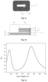
- Fig. 1a shows a schematic diagram of an optical anti-counterfeiting element according to an embodiment of the disclosure.
- the optical anti-counterfeiting element 1 has a hollow area 31 and a non-hollow area 32.
- a graphic arrow formed by the hollow area 31 may be seen, and the non-hollow area is an optically variable film, so that obvious contrast is formed.
- Fig. 1b shows a schematic diagram of a cross-sectional view of the optical anti-counterfeiting element as shown in Fig. 1a .
- a substrate 2 is a transparent substrate.
- an Fabry-Perot filter structure hereinafter referred to as an 'optically variable film'
- the substrate 2 is PET, and the substrate 2 is transparent.
- the absorbing layer 41 is aluminum-chromium alloy (Al/Cr) having an atomic ratio of metal aluminum to metal chromium of 9: 1 and a thickness of about 8 nm.
- the dielectric layer 42 is silicon dioxide and has a thickness of about 400 nm.
- the reflecting layer 43 is metal aluminum and has a thickness of 30 nm.
- Fig. 2a shows a reflection spectrogram of an optically variable film with chromium as an absorbing layer
- Fig. 2b shows a reflection spectrogram of an optically variable film with aluminum-chromium alloy as an absorbing layer
- Fig. 2c shows a reflection spectrogram of an optically variable film with aluminum as an absorbing layer.
- Table 1 shows color parameters of the optically variable film when the above three materials are used as the absorbing layers respectively.
- Table 1 Absorbing layer types h (Hue/Hue angle) C (Saturation) L (Brightness) Cr 85.9° 64.4 72.7 Al/Cr 80.9° 48.7 74 Al 111° 28 83.8
- Figs. 3a-3c illustrate schematic diagrams of manufacturing process of the optical anti-counterfeiting element. The specific flow is as follows.
- an alloy absorbing layer 41 for example, Al/Cr alloy
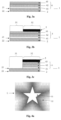
- Fig. 4a shows a schematic diagram of another optical anti-counterfeiting element according to an embodiment of the disclosure.
- a hollow area 31 is in a pentagram shape and is hollowed-out and light-transmitting integrally;
- a non-hollow area 32 has an optically variable film which is colorful, and on the basis of the colorful feature, light and shade difference is achieved.
- Fig. 4b is a schematic diagram of a cross-sectional view of the optical anti-counterfeiting element as shown in Fig. 4a .
- a surface relief structure layer 6 is arranged on a transparent substrate 2 (for example, PET), the surface relief structure layer includes a first area aligned with a hollow area 31 of the optical anti-counterfeiting element and a second area aligned with a non-hollow area 32 of the optical anti-counterfeiting element, the first area includes a first grating microstructure 61 (for example, symmetric wedge-shaped gratings), and the second area includes a grating microstructure 62 (for example, a blazed grating).
- a transparent substrate 2 for example, PET
- the surface relief structure layer includes a first area aligned with a hollow area 31 of the optical anti-counterfeiting element and a second area aligned with a non-hollow area 32 of the optical anti-counterfeiting element
- the first area includes
- a Fabry-Perot filter structure 4 (namely, an optically variable film) covering the grating microstructure (62) of the second area in a same shape is provided, an alloy absorbing layer (41) (for example, Cr/Fe alloy) in the Fabry-Perot filter structure is in contact with the second area, a dielectric layer (42) is cryolite, for example, and a reflecting layer is silver, for example. No optically variable film is arranged on the grating microstructure 61.
- a protection layer 5 may be formed on the reflecting layer 43.
- the surface relief structure layer 6 may be an ultraviolet curing material or a thermoforming material, and the required microstructure may be formed on the transparent substrate 2 under specific conditions.
- the grating microstructure 61 in the hollow area 31 may be symmetric wedge-shaped gratings with a feature period (or feature size) of 20 ⁇ m and a depth of 8 ⁇ m.
- the grating microstructure 62 in the non-hollow area 32 is a blazed grating with a feature period of 15 ⁇ m, and a depth changing from 0.1 ⁇ m to 5 ⁇ m according to a certain arrangement mode.
- the change rule may be seen in the Chinese patent application with the publication number of CN102712207B , and various features such as dynamic sense, relief and three-dimensional sense may be formed.
- the dielectric layer 42 is cryolite with a thickness of about 520 nm; and
- the reflecting layer 43 is metal silver with a thickness of about 50 nm.
- the optical anti-counterfeiting element 1 When viewed from the front, the optical anti-counterfeiting element 1 shows the pattern as shown in the first figure (1 ) in Fig. 4c , the five-pointed star of the middle hollow area 31 shows a completely hollowed-out transparent state, the outline of the innermost five-pointed star of the non-hollow area 32 shows a bright magenta color, and the brightness of the other areas is relatively low.
- the reason is that through proper adjustment and setting of the angle of the blazed grating, only light reflected by the blazed grating on the innermost enters the eyes of an observer during front observation, then only the pattern on the innermost shows bright magenta, the blazed grating in other areas reflects the light to other positions so that the light may not enter the eyes of the observer, therefore, the brightness is relatively low, and obvious light-shade contrast is formed.
- the optical anti-counterfeiting element 1 is inclined, at another angle, the blazed grating in the middle may reflect light into the eyes of the observer, so that the brightness of the middle becomes relatively strong and the brightness at other positions is relatively low.
- the outermost blazed grating reflects light into the eyes of the observer, and then the outermost circle becomes the brightest.
- the bright magenta profile spreads from the center to the outside with the action of inclining throughout the course of inclining change (referring to the second figure (2 ) and the third figure (3 ) in Fig. 4c ), and a dynamic change with the inclining process is formed.
- the hollow area is determined by a specific microstructure, the appearance of which is represented by a dynamic contour having a hollowed-out shape, the dynamic contour may not be overlapped with the hollowed-out shape, or the hollow area and the dynamic area are strictly defined and positioned, and there is no superposition interference between the two.
- the hollow area is free of any optically variable plating layer, and the appearance effect of complete transparency is shown.
- Fig. 5a shows a schematic diagram of a cross-sectional view of an optical anti-counterfeiting element with a release layer and a lacquer layer according to an embodiment of the disclosure.
- the structure of the optical anti-counterfeiting element 1 is similar to that of Figs. 4a-4b , with the exception that a release layer 7 is formed between a substrate 2 and a surface relief structure layer 6, with a lacquer layer 8 on the outermost layer of the element, and with the surface of the lacquer layer 8 planarized.
- the release layer 7 may be an acrylate material or the like and is characterized by being able to be stripped from the substrate 2 when heated, the lacquer layer 8 allows the optical anti-counterfeiting element 1 to be bonded to a product bearing substrate 9 (for example, paper or BOPP or the like), the optical anti-counterfeiting element 1 is transferred to a product bearing substrate 9 (for example, paper or BOPP), and the surface originally in contact with the substrate 2 directly faces an observer, as shown in Fig. 5b .
- a product bearing substrate 9 for example, paper or BOPP or the like
- an absorbing layer of a common optically variable film is metal chromium
- the absorbing layer is still reserved, so that after transferring, the observer may still observe the absorbing layer chromium, the whole appearance is dark gray, and the appearance effect is affected.
- the absorbing layer of an alloy is adopted, a hollow area is completely corroded and is in a completely transparent state, so that a better optical effect may be realized.
- Figs. 6a-6d show a manufacturing method of an optical anti-counterfeiting element 1.
- the method may include the following steps. (a): providing a transparent substrate 2; (b): forming a surface relief structure layer 6 on the substrate 2 in a thermal forming or ultraviolet curing manner, as shown in Fig. 6a; (c) : sequentially depositing an alloy absorbing layer 41, a dielectric layer 42 and a reflecting layer 43 are sequentially on the surface relief structure layer 6, so that interference color layers of a Fabry-Perot filter structure are formed, as shown in Fig. 6b ; (d) : coating a protection layer 5 on one side of the reflecting layer 43, and the protection layer, for example, may be protective glue, as shown in Fig.
- the manufacturing method of the optical anti-counterfeiting element according to the embodiment is the same as or similar to the specific implementation details and benefits of the optical anti-counterfeiting element according to the above embodiment, and will not be elaborated here.
- optical anti-counterfeiting element may also be used as a label, a logo, a wide strip, a transparent window, a coating film and the like, and may be adhered to various articles by various bonding mechanisms, for example, transferred to high security products such as banknotes and credit cards and high added value products.
- the embodiment of the disclosure also provides anti-counterfeiting products, such as banknotes, credit cards, passports and securities, including the optical anti-counterfeiting element described above.
- the foregoing storage medium includes any medium that be store program codes, such as a U disk, a removable hard disk, a Read-Only Memory (ROM), a Random Access Memory (RAM), a magnetic disk, or an optical disc.
Landscapes
- Engineering & Computer Science (AREA)
- Manufacturing & Machinery (AREA)
- Chemical & Material Sciences (AREA)
- Chemical Kinetics & Catalysis (AREA)
- General Chemical & Material Sciences (AREA)
- Physics & Mathematics (AREA)
- General Physics & Mathematics (AREA)
- Optics & Photonics (AREA)
- Credit Cards Or The Like (AREA)
- Optical Filters (AREA)
- Spectroscopy & Molecular Physics (AREA)
Claims (13)
- Élément anti-contrefaçon optique, comprenant :un substrat (2), ayant une première surface (21) et une deuxième surface (22) qui sont opposées l'une à l'autre ; etune couche de couleur d'interférence située sur la première surface (21) du substrat (2), la couche de couleur d'interférence étant située dans une zone non creuse (32) de l'élément anti-contrefaçon optique et n'étant pas située dans une zone creuse (31), la couche de couleur d'interférence étant une structure de filtre de Fabry-Perot (4), une couche absorbante (41) de la structure de filtre de Fabry-Perot (4) étant en contact avec le substrat (2), et un matériau de la couche absorbante (41) étant un alliage,caractérisé en ce que l'alliage est formé par au moins deux métaux, un métal formant l'alliage est un métal gris, et un autre métal est un métal susceptible à la corrosion par solution, de sorte que lors de la fabrication de l'élément anti-contrefaçon optique, la couche de couleur d'interférence dans une zone creuse (31) soit corrodée complètement pour réaliser tout le creusement de la couche de couleur d'interférence tout en maintenant une saturation de couleur élevée de l'élément anti-contrefaçon optique.
- Élément anti-contrefaçon optique, comprenant :un substrat (2), ayant une première surface (21) et une deuxième surface (22) qui sont opposées l'une à l'autre ;une couche de structure de relief de surface (6) située sur la première surface (21) du substrat (2), comprenant une première zone alignée avec une zone creuse (31) de l'élément anti-contrefaçon optique et une deuxième zone alignée avec une zone non creuse (32) de l'élément anti-contrefaçon optique, la première zone comprenant une première microstructure de réseau, la deuxième zone comprenant une deuxième microstructure de réseau et/ou une structure plate, un rapport profondeur-sur-largeur de la première microstructure de réseau étant supérieur à un rapport profondeur-sur-largeur de la deuxième microstructure de réseau, et/ou un volume-sur-surface spécifique de la première microstructure de réseau étant supérieur à un volume-sur-surface spécifique de la deuxième microstructure de réseau ; etune couche de couleur d'interférence recouvrant la deuxième zone dans la même forme, la couche de couleur d'interférence étant située dans la zone non creuse (32) de l'élément anti-contrefaçon optique et n'étant pas située dans la zone creuse (31), la couche de couleur d'interférence étant une structure de filtre de Fabry-Perot (4), une couche absorbante (41) de la structure de filtre de Fabry-Perot (4) étant en contact avec la deuxième zone, et un matériau de la couche absorbante étant un alliage,caractérisé en ce que l'alliage est formé par au moins deux métaux, un métal formant l'alliage est un métal gris, et un autre métal est un métal susceptible à la corrosion par solution, de sorte que lors de la fabrication de l'élément anti-contrefaçon optique, la couche de couleur d'interférence dans une zone creuse (31) soit corrodée complètement pour réaliser tout le creusement de la couche de couleur d'interférence tout en maintenant une saturation de couleur élevée de l'élément anti-contrefaçon optique.
- Élément anti-contrefaçon optique selon la revendication 1 ou 2,l'alliage étant un ou plusieurs parmi les suivants : alliage aluminium/chrome, alliage aluminium/nickel, alliage aluminium/silicium, fer/chrome ou alliage aluminium/fer/chrome ; et/ouune épaisseur de la couche absorbante (41) se situant dans la plage de 2 nm à 30 nm ; et/ouun matériau d'une couche diélectrique (42) dans la structure de filtre de Fabry-Perot (4) étant un matériau à indice de réfraction bas ayant un indice de réfraction plus petit que 1,8 ou un matériau à indice de réfraction élevé ayant un indice de réfraction supérieur à 1,8, etun matériau d'une couche réfléchissante (43) dans la structure de filtre de Fabry-Perot (4) comprenant l'un ou plusieurs parmi les suivants : aluminium, argent, étain, nickel, chrome, platine, cuivre, or, silicium ou une combinaison d'aluminium, d'argent, d'étain, de nickel, de chrome, de platine, de cuivre, d'or et de silicium ; et/oule substrat étant transparent ou semitransparent.
- Élément anti-contrefaçon optique selon la revendication 1 ou 2, comprenant en outre une couche de protection (5) formée sur la couche de couleur d'interférence.
- Élément anti-contrefaçon optique selon la revendication 2,une taille de caractéristique de la première microstructure de réseau et/ou la deuxième microstructure de réseau se situant dans la plage de 100 nm à 100 µm ;le rapport profondeur-sur-largeur de la deuxième microstructure de réseau étant plus petit que 0,2, et/ou le volume-sur-surface spécifique de la deuxième microstructure de réseau étant plus petit que 0,2, et/oula première microstructure de réseau et/ou la deuxième microstructure de réseau étant l'un ou plusieurs parmi les suivants : un réseau sublongueur d'onde, un réseau holographique, un réseau blazé, une lentille sphérique ou une lentille cylindrique.
- Élément anti-contrefaçon optique selon la revendication 2, comprenant en outre : une couche pelée formée entre le substrat et la couche de structure de relief de surface ; et une couche de laque recouvrant la zone creuse et/ou la zone non creuse, et une surface de la couche de laque étant planarisée.
- Procédé de fabrication d'un élément anti-contrefaçon optique, comprenant :la fourniture d'un substrat (2), et le substrat (2) ayant une première surface (21) et une deuxième surface (22) qui sont opposées l'une à l'autre ;le dépôt de manière séquentielle d'une couche absorbante (41), d'une couche diélectrique (42) et d'une couche réfléchissante (43) qui sont formées par un alliage sur la première surface (21) du substrat (2), et la couche absorbante (41), la couche diélectrique (42) et la couche réfléchissante (43) formant une couche de couleur d'interférence d'une structure de filtre de Fabry-Perot (4) ;l'impression d'une couche de protection (5) sur la couche réfléchissante (43) ;l'immersion de la structure formée dans l'étape précédente dans une solution corrosive de sorte que la couche de couleur d'interférence dans une zone creuse (31) de l'élément anti-contrefaçon optique soit corrodée ; etle retrait et le lavage de la structure corrodée,caractérisé en ce que l'alliage est formé par au moins deux métaux, un métal formant l'alliage est un métal gris, et un autre métal est un métal susceptible à la corrosion par solution, de sorte que lors de la fabrication de l'élément anti-contrefaçon optique, la couche de couleur d'interférence dans une zone creuse (31) soit corrodée complètement pour réaliser tout le creusement de la couche de couleur d'interférence tout en maintenant une saturation de couleur élevée de l'élément anti-contrefaçon optique.
- Procédé de fabrication d'un élément anti-contrefaçon optique, comprenant :la fourniture d'un substrat (2), et le substrat (2) ayant une première surface (21) et une deuxième surface (22) qui sont opposées l'une à l'autre ;la formation d'une couche de structure de relief de surface (6) sur la première surface (21) du substrat (2), et la couche de structure de relief de surface (6) comprenant une première zone alignée avec une zone creuse (31) de l'élément anti-contrefaçon optique et une deuxième zone alignée avec une zone non creuse (32) de l'élément anti-contrefaçon optique, la première zone comprenant une première microstructure de réseau, la deuxième zone comprenant une deuxième microstructure de réseau et/ou une structure plate, un rapport profondeur-sur-largeur de la première microstructure de réseau étant supérieur à un rapport profondeur-sur-largeur de la deuxième microstructure de réseau, et/ou un volume-sur-surface spécifique de la première microstructure de réseau étant supérieur à un volume-sur-surface spécifique de la deuxième microstructure de réseau ;le dépôt de manière séquentielle d'une couche absorbante (41), d'une couche diélectrique (42) et d'une couche réfléchissante (43) qui sont formées par un alliage sur la couche de structure de relief de surface (6), et la couche absorbante (41), la couche diélectrique (42) et la couche réfléchissante (43) formant une couche de couleur d'interférence d'une structure de filtre de Fabry-Perot (4) ;l'impression d'une couche de protection (5) sur la couche réfléchissante (43) ;l'immersion de la structure formée dans l'étape précédente dans une solution corrosive de sorte que la couche de couleur d'interférence dans la première zone soit corrodée ; etle retrait et le lavage de la structure corrodée,caractérisé en ce que l'alliage est formé par au moins deux métaux, un métal formant l'alliage est un métal gris, et un autre métal est un métal susceptible à la corrosion par solution, de sorte que lors de la fabrication de l'élément anti-contrefaçon optique, la couche de couleur d'interférence dans une zone creuse (31) soit corrodée complètement pour réaliser tout le creusement de la couche de couleur d'interférence tout en maintenant une saturation de couleur élevée de l'élément anti-contrefaçon optique.
- Procédé de fabrication selon la revendication 7 ou 8, l'alliage étant l'un ou plusieurs parmi les suivants : alliage aluminium/chrome, alliage aluminium/nickel, alliage aluminium/silicium, fer/chrome ou alliage aluminium/fer/chrome ; et/ouune épaisseur de la couche absorbante (41) se situant dans la plage de 2 nm à 30 nm ; et/oule substrat (2) étant transparent ou semitransparent.
- Procédé de fabrication selon la revendication 7 ou 8,un matériau de la couche diélectrique (42) étant un matériau à indice de réfraction bas ayant un indice de réfraction plus petit que 1,8 ou un matériau à indice de réfraction élevé ayant un indice de réfraction supérieur à 1,8, etun matériau de la couche réfléchissante (43) comprenant l'un ou plusieurs parmi les suivants : aluminium, argent, étain, nickel, chrome, platine, cuivre, or, silicium ou une combinaison d'aluminium, d'argent, d'étain, de nickel, de chrome, de platine, de cuivre, d'or et de silicium.
- Procédé de fabrication selon la revendication 8,une taille de caractéristique de la première microstructure de réseau et/ou la deuxième microstructure de réseau se situant dans la plage de 100 nm à 100 µm ;le rapport profondeur-sur-largeur de la deuxième microstructure de réseau étant plus petit que 0,2, et/ou le volume-sur-surface spécifique de la deuxième microstructure de réseau étant plus petit que 0,2, et/oula première microstructure de réseau et/ou la deuxième microstructure de réseau étant l'un ou plusieurs parmi les suivants : un réseau sublongueur d'onde, un réseau holographique, un réseau blazé, une lentille sphérique ou une lentille cylindrique.
- Procédé de fabrication selon la revendication 7 ou 8, chaque couche de la couche de couleur d'interférence de la structure de filtre de Fabry-Perot (4) étant formée par l'un ou plusieurs des procédés suivants : un procédé de dépôt par évaporation, un procédé de dépôt par évaporation par faisceau d'électrons ou un procédé de dépôt par pulvérisation par magnétron.
- Produit anti-contrefaçon optique, comprenant l'élément anti-contrefaçon optique selon l'une quelconque des revendications 1 à 6.
Applications Claiming Priority (2)
| Application Number | Priority Date | Filing Date | Title |
|---|---|---|---|
| CN201910336073.0A CN111845148B (zh) | 2019-04-24 | 2019-04-24 | 光学防伪元件及其制作方法 |
| PCT/CN2020/083197 WO2020216043A1 (fr) | 2019-04-24 | 2020-04-03 | Élément optique anti-contrefaçon et son procédé de fabrication |
Publications (3)
| Publication Number | Publication Date |
|---|---|
| EP3960482A1 EP3960482A1 (fr) | 2022-03-02 |
| EP3960482A4 EP3960482A4 (fr) | 2023-01-11 |
| EP3960482B1 true EP3960482B1 (fr) | 2024-09-25 |
Family
ID=72940698
Family Applications (1)
| Application Number | Title | Priority Date | Filing Date |
|---|---|---|---|
| EP20794469.5A Active EP3960482B1 (fr) | 2019-04-24 | 2020-04-03 | Élément optique anti-contrefaçon et son procédé de fabrication |
Country Status (4)
| Country | Link |
|---|---|
| US (1) | US12257857B2 (fr) |
| EP (1) | EP3960482B1 (fr) |
| CN (1) | CN111845148B (fr) |
| WO (1) | WO2020216043A1 (fr) |
Families Citing this family (2)
| Publication number | Priority date | Publication date | Assignee | Title |
|---|---|---|---|---|
| CN113625383A (zh) * | 2021-08-30 | 2021-11-09 | 奥斯特原点(广东)科技有限公司 | 一种光学防伪元件、其加工方法以及光学防伪产品 |
| DE102022002765A1 (de) | 2022-07-29 | 2024-02-01 | Giesecke+Devrient Currency Technology Gmbh | Sicherheitselement und mit dem Sicherheitselement ausgestattetes Wertdokument |
Family Cites Families (19)
| Publication number | Priority date | Publication date | Assignee | Title |
|---|---|---|---|---|
| US7667895B2 (en) | 1999-07-08 | 2010-02-23 | Jds Uniphase Corporation | Patterned structures with optically variable effects |
| US7645510B2 (en) * | 2002-09-13 | 2010-01-12 | Jds Uniphase Corporation | Provision of frames or borders around opaque flakes for covert security applications |
| CN1597334B (zh) * | 2003-07-14 | 2011-03-30 | Jds尤尼费斯公司 | 防伪线和在薄板上制造光学可变装置的方法 |
| CN1854944B (zh) * | 2005-04-20 | 2011-02-09 | Jds尤尼弗思公司 | 具有光学可变效果的图案化结构 |
| DE102008036402B3 (de) * | 2008-08-01 | 2009-09-17 | Bundesdruckerei Gmbh | Goniolumineszentes Sicherheitselement und Verfahren zu dessen Herstellung |
| DE102009056933A1 (de) * | 2009-12-04 | 2011-06-09 | Giesecke & Devrient Gmbh | Sicherheitselement mit Farbfilter, Wertdokument mit so einem solchen Sicherheitselement sowie Herstellungsverfahren eines solchen Sicherheitselementes |
| DE102010047250A1 (de) | 2009-12-04 | 2011-06-09 | Giesecke & Devrient Gmbh | Sicherheitselement, Wertdokument mit einem solchen Sicherheitselement sowie Herstellungsverfahren eines Sicherheitselementes |
| CN101767511B (zh) | 2010-01-12 | 2012-11-28 | 中钞特种防伪科技有限公司 | 光学防伪元件及带有该防伪元件的产品 |
| EP3351981B1 (fr) * | 2011-06-23 | 2025-04-02 | Viavi Solutions Inc. | Dispositifs à variations chromatiques multiples |
| CN103963510B (zh) * | 2013-01-29 | 2015-12-23 | 中钞特种防伪科技有限公司 | 一种制备光学防伪元件的方法 |
| US20140367957A1 (en) | 2013-06-13 | 2014-12-18 | Ad Lucem Corp. | Moiré magnification systems |
| CN104647937B (zh) * | 2013-11-22 | 2017-04-12 | 中钞特种防伪科技有限公司 | 一种制备光学防伪元件的方法 |
| CN105015216B (zh) * | 2014-04-29 | 2017-06-16 | 中钞特种防伪科技有限公司 | 一种光学防伪元件及制备光学防伪元件的方法 |
| CN104385800B (zh) | 2014-10-16 | 2017-10-24 | 中钞特种防伪科技有限公司 | 光学防伪元件及光学防伪产品 |
| US20180170093A1 (en) | 2015-06-30 | 2018-06-21 | Spectral Devices Inc. | Flexible pixelated fabry-perot filter |
| DE102015010744A1 (de) | 2015-08-17 | 2017-02-23 | Giesecke & Devrient Gmbh | Sicherheitselement, Verfahren zum Herstellen desselben und mit dem Sicherheitselement ausgestatteter Datenträger |
| CN106891637B (zh) * | 2015-12-17 | 2018-12-21 | 中钞特种防伪科技有限公司 | 光学防伪元件及其制备方法 |
| CN108693582A (zh) * | 2017-04-12 | 2018-10-23 | 中钞特种防伪科技有限公司 | 一种光学防伪元件和产品 |
| CN108773229B (zh) | 2018-06-12 | 2019-11-15 | 王海宇 | 防伪装置及制造方法和安全票证 |
-
2019
- 2019-04-24 CN CN201910336073.0A patent/CN111845148B/zh active Active
-
2020
- 2020-04-03 WO PCT/CN2020/083197 patent/WO2020216043A1/fr not_active Ceased
- 2020-04-03 EP EP20794469.5A patent/EP3960482B1/fr active Active
- 2020-04-03 US US17/594,579 patent/US12257857B2/en active Active
Also Published As
| Publication number | Publication date |
|---|---|
| US12257857B2 (en) | 2025-03-25 |
| CN111845148B (zh) | 2022-04-05 |
| EP3960482A1 (fr) | 2022-03-02 |
| EP3960482A4 (fr) | 2023-01-11 |
| US20220184992A1 (en) | 2022-06-16 |
| WO2020216043A1 (fr) | 2020-10-29 |
| CN111845148A (zh) | 2020-10-30 |
Similar Documents
| Publication | Publication Date | Title |
|---|---|---|
| US5009486A (en) | Form depicting, optical interference authenticating device | |
| EP0341002B1 (fr) | Structure de couches minces ayant de propriétés magnétiques et de modification de couleur | |
| JP4256343B2 (ja) | 様々な層厚を有するスペーサ層を備えた光学可変素子 | |
| US9308774B2 (en) | Security element comprising a screened layer | |
| CN111823749B (zh) | 光学防伪元件及其制作方法、光学防伪产品 | |
| CN103921582B (zh) | 一种变色烫印膜及其制造方法 | |
| HK1005756B (en) | Thin film structure having magnetic and colour shifting properties | |
| US20120242075A1 (en) | Gold-colored thin-film element with multilayer structure | |
| CN102112325A (zh) | 具有可光变元件的安全元件 | |
| JP2006504545A (ja) | 薄膜層配列を備えた光学的に変化する素子 | |
| CN110520304B (zh) | 具有浮雕结构的防伪元件及其生产方法 | |
| KR20050006251A (ko) | 부분적인 투명 소자를 구비한 광학적 가변 소자 | |
| EP3960482B1 (fr) | Élément optique anti-contrefaçon et son procédé de fabrication | |
| JP2018509313A (ja) | 多層体及び多層体の製造方法 | |
| EP4019271A1 (fr) | Élément anti-contrefaçon optique et produit anti-contrefaçon optique | |
| CN111098620A (zh) | 光学防伪元件、光学防伪元件的制备方法及光学防伪产品 | |
| EP3535134B1 (fr) | Dispositifs de sécurité et leurs procédés de fabrication | |
| CN111716935A (zh) | 光学防伪元件及光学防伪产品 | |
| EP4011637B1 (fr) | Élément anti-contrefaçon optique et produit anti-contrefaçon optique | |
| WO2020187287A1 (fr) | Élément anti-contrefaçon optique et produit anti-contrefaçon optique | |
| US20240239129A1 (en) | Functional element, a method for producing a functional element, and a product | |
| CN112606588A (zh) | 一种光学变色烫金材料 | |
| CN116075435B (zh) | 光学可变的防伪元件 | |
| CN118276207A (zh) | 一种光学防伪元件及光学防伪产品 | |
| KR19990026684A (ko) | 다양한 색상을 나타내는 색거울 및 이의 제조방법 |
Legal Events
| Date | Code | Title | Description |
|---|---|---|---|
| STAA | Information on the status of an ep patent application or granted ep patent |
Free format text: STATUS: THE INTERNATIONAL PUBLICATION HAS BEEN MADE |
|
| PUAI | Public reference made under article 153(3) epc to a published international application that has entered the european phase |
Free format text: ORIGINAL CODE: 0009012 |
|
| STAA | Information on the status of an ep patent application or granted ep patent |
Free format text: STATUS: REQUEST FOR EXAMINATION WAS MADE |
|
| 17P | Request for examination filed |
Effective date: 20211103 |
|
| AK | Designated contracting states |
Kind code of ref document: A1 Designated state(s): AL AT BE BG CH CY CZ DE DK EE ES FI FR GB GR HR HU IE IS IT LI LT LU LV MC MK MT NL NO PL PT RO RS SE SI SK SM TR |
|
| DAV | Request for validation of the european patent (deleted) | ||
| DAX | Request for extension of the european patent (deleted) | ||
| REG | Reference to a national code |
Free format text: PREVIOUS MAIN CLASS: B42D0025400000 Ipc: B42D0025324000 Ref country code: DE Ref legal event code: R079 Ref document number: 602020038386 Country of ref document: DE |
|
| A4 | Supplementary search report drawn up and despatched |
Effective date: 20221214 |
|
| RIC1 | Information provided on ipc code assigned before grant |
Ipc: B42D 25/45 20140101ALI20221208BHEP Ipc: B42D 25/445 20140101ALI20221208BHEP Ipc: B42D 25/425 20140101ALI20221208BHEP Ipc: B42D 25/373 20140101ALI20221208BHEP Ipc: B42D 25/351 20140101ALI20221208BHEP Ipc: B42D 25/328 20140101ALI20221208BHEP Ipc: B42D 25/324 20140101AFI20221208BHEP |
|
| GRAP | Despatch of communication of intention to grant a patent |
Free format text: ORIGINAL CODE: EPIDOSNIGR1 |
|
| STAA | Information on the status of an ep patent application or granted ep patent |
Free format text: STATUS: GRANT OF PATENT IS INTENDED |
|
| INTG | Intention to grant announced |
Effective date: 20240628 |
|
| GRAS | Grant fee paid |
Free format text: ORIGINAL CODE: EPIDOSNIGR3 |
|
| GRAA | (expected) grant |
Free format text: ORIGINAL CODE: 0009210 |
|
| STAA | Information on the status of an ep patent application or granted ep patent |
Free format text: STATUS: THE PATENT HAS BEEN GRANTED |
|
| AK | Designated contracting states |
Kind code of ref document: B1 Designated state(s): AL AT BE BG CH CY CZ DE DK EE ES FI FR GB GR HR HU IE IS IT LI LT LU LV MC MK MT NL NO PL PT RO RS SE SI SK SM TR |
|
| REG | Reference to a national code |
Ref country code: GB Ref legal event code: FG4D |
|
| REG | Reference to a national code |
Ref country code: CH Ref legal event code: EP |
|
| P01 | Opt-out of the competence of the unified patent court (upc) registered |
Free format text: CASE NUMBER: APP_48295/2024 Effective date: 20240822 |
|
| REG | Reference to a national code |
Ref country code: DE Ref legal event code: R096 Ref document number: 602020038386 Country of ref document: DE |
|
| REG | Reference to a national code |
Ref country code: IE Ref legal event code: FG4D |
|
| REG | Reference to a national code |
Ref country code: LT Ref legal event code: MG9D |
|
| PG25 | Lapsed in a contracting state [announced via postgrant information from national office to epo] |
Ref country code: NO Free format text: LAPSE BECAUSE OF FAILURE TO SUBMIT A TRANSLATION OF THE DESCRIPTION OR TO PAY THE FEE WITHIN THE PRESCRIBED TIME-LIMIT Effective date: 20241225 |
|
| PG25 | Lapsed in a contracting state [announced via postgrant information from national office to epo] |
Ref country code: GR Free format text: LAPSE BECAUSE OF FAILURE TO SUBMIT A TRANSLATION OF THE DESCRIPTION OR TO PAY THE FEE WITHIN THE PRESCRIBED TIME-LIMIT Effective date: 20241226 Ref country code: FI Free format text: LAPSE BECAUSE OF FAILURE TO SUBMIT A TRANSLATION OF THE DESCRIPTION OR TO PAY THE FEE WITHIN THE PRESCRIBED TIME-LIMIT Effective date: 20240925 |
|
| PG25 | Lapsed in a contracting state [announced via postgrant information from national office to epo] |
Ref country code: BG Free format text: LAPSE BECAUSE OF FAILURE TO SUBMIT A TRANSLATION OF THE DESCRIPTION OR TO PAY THE FEE WITHIN THE PRESCRIBED TIME-LIMIT Effective date: 20240925 |
|
| PG25 | Lapsed in a contracting state [announced via postgrant information from national office to epo] |
Ref country code: LV Free format text: LAPSE BECAUSE OF FAILURE TO SUBMIT A TRANSLATION OF THE DESCRIPTION OR TO PAY THE FEE WITHIN THE PRESCRIBED TIME-LIMIT Effective date: 20240925 |
|
| PG25 | Lapsed in a contracting state [announced via postgrant information from national office to epo] |
Ref country code: RS Free format text: LAPSE BECAUSE OF FAILURE TO SUBMIT A TRANSLATION OF THE DESCRIPTION OR TO PAY THE FEE WITHIN THE PRESCRIBED TIME-LIMIT Effective date: 20241225 |
|
| REG | Reference to a national code |
Ref country code: NL Ref legal event code: MP Effective date: 20240925 |
|
| PG25 | Lapsed in a contracting state [announced via postgrant information from national office to epo] |
Ref country code: RS Free format text: LAPSE BECAUSE OF FAILURE TO SUBMIT A TRANSLATION OF THE DESCRIPTION OR TO PAY THE FEE WITHIN THE PRESCRIBED TIME-LIMIT Effective date: 20241225 Ref country code: NO Free format text: LAPSE BECAUSE OF FAILURE TO SUBMIT A TRANSLATION OF THE DESCRIPTION OR TO PAY THE FEE WITHIN THE PRESCRIBED TIME-LIMIT Effective date: 20241225 Ref country code: LV Free format text: LAPSE BECAUSE OF FAILURE TO SUBMIT A TRANSLATION OF THE DESCRIPTION OR TO PAY THE FEE WITHIN THE PRESCRIBED TIME-LIMIT Effective date: 20240925 Ref country code: GR Free format text: LAPSE BECAUSE OF FAILURE TO SUBMIT A TRANSLATION OF THE DESCRIPTION OR TO PAY THE FEE WITHIN THE PRESCRIBED TIME-LIMIT Effective date: 20241226 Ref country code: FI Free format text: LAPSE BECAUSE OF FAILURE TO SUBMIT A TRANSLATION OF THE DESCRIPTION OR TO PAY THE FEE WITHIN THE PRESCRIBED TIME-LIMIT Effective date: 20240925 Ref country code: BG Free format text: LAPSE BECAUSE OF FAILURE TO SUBMIT A TRANSLATION OF THE DESCRIPTION OR TO PAY THE FEE WITHIN THE PRESCRIBED TIME-LIMIT Effective date: 20240925 |
|
| REG | Reference to a national code |
Ref country code: AT Ref legal event code: MK05 Ref document number: 1726363 Country of ref document: AT Kind code of ref document: T Effective date: 20240925 |
|
| PG25 | Lapsed in a contracting state [announced via postgrant information from national office to epo] |
Ref country code: NL Free format text: LAPSE BECAUSE OF FAILURE TO SUBMIT A TRANSLATION OF THE DESCRIPTION OR TO PAY THE FEE WITHIN THE PRESCRIBED TIME-LIMIT Effective date: 20240925 |
|
| PG25 | Lapsed in a contracting state [announced via postgrant information from national office to epo] |
Ref country code: PT Free format text: LAPSE BECAUSE OF FAILURE TO SUBMIT A TRANSLATION OF THE DESCRIPTION OR TO PAY THE FEE WITHIN THE PRESCRIBED TIME-LIMIT Effective date: 20250127 Ref country code: IS Free format text: LAPSE BECAUSE OF FAILURE TO SUBMIT A TRANSLATION OF THE DESCRIPTION OR TO PAY THE FEE WITHIN THE PRESCRIBED TIME-LIMIT Effective date: 20250125 |
|
| PG25 | Lapsed in a contracting state [announced via postgrant information from national office to epo] |
Ref country code: RO Free format text: LAPSE BECAUSE OF FAILURE TO SUBMIT A TRANSLATION OF THE DESCRIPTION OR TO PAY THE FEE WITHIN THE PRESCRIBED TIME-LIMIT Effective date: 20240925 Ref country code: SM Free format text: LAPSE BECAUSE OF FAILURE TO SUBMIT A TRANSLATION OF THE DESCRIPTION OR TO PAY THE FEE WITHIN THE PRESCRIBED TIME-LIMIT Effective date: 20240925 |
|
| PG25 | Lapsed in a contracting state [announced via postgrant information from national office to epo] |
Ref country code: ES Free format text: LAPSE BECAUSE OF FAILURE TO SUBMIT A TRANSLATION OF THE DESCRIPTION OR TO PAY THE FEE WITHIN THE PRESCRIBED TIME-LIMIT Effective date: 20240925 |
|
| PG25 | Lapsed in a contracting state [announced via postgrant information from national office to epo] |
Ref country code: AT Free format text: LAPSE BECAUSE OF FAILURE TO SUBMIT A TRANSLATION OF THE DESCRIPTION OR TO PAY THE FEE WITHIN THE PRESCRIBED TIME-LIMIT Effective date: 20240925 Ref country code: EE Free format text: LAPSE BECAUSE OF FAILURE TO SUBMIT A TRANSLATION OF THE DESCRIPTION OR TO PAY THE FEE WITHIN THE PRESCRIBED TIME-LIMIT Effective date: 20240925 |
|
| PG25 | Lapsed in a contracting state [announced via postgrant information from national office to epo] |
Ref country code: PL Free format text: LAPSE BECAUSE OF FAILURE TO SUBMIT A TRANSLATION OF THE DESCRIPTION OR TO PAY THE FEE WITHIN THE PRESCRIBED TIME-LIMIT Effective date: 20240925 Ref country code: CZ Free format text: LAPSE BECAUSE OF FAILURE TO SUBMIT A TRANSLATION OF THE DESCRIPTION OR TO PAY THE FEE WITHIN THE PRESCRIBED TIME-LIMIT Effective date: 20240925 |
|
| PG25 | Lapsed in a contracting state [announced via postgrant information from national office to epo] |
Ref country code: IT Free format text: LAPSE BECAUSE OF FAILURE TO SUBMIT A TRANSLATION OF THE DESCRIPTION OR TO PAY THE FEE WITHIN THE PRESCRIBED TIME-LIMIT Effective date: 20240925 Ref country code: SK Free format text: LAPSE BECAUSE OF FAILURE TO SUBMIT A TRANSLATION OF THE DESCRIPTION OR TO PAY THE FEE WITHIN THE PRESCRIBED TIME-LIMIT Effective date: 20240925 |
|
| REG | Reference to a national code |
Ref country code: DE Ref legal event code: R097 Ref document number: 602020038386 Country of ref document: DE |
|
| PGFP | Annual fee paid to national office [announced via postgrant information from national office to epo] |
Ref country code: DE Payment date: 20250417 Year of fee payment: 6 |
|
| PG25 | Lapsed in a contracting state [announced via postgrant information from national office to epo] |
Ref country code: DK Free format text: LAPSE BECAUSE OF FAILURE TO SUBMIT A TRANSLATION OF THE DESCRIPTION OR TO PAY THE FEE WITHIN THE PRESCRIBED TIME-LIMIT Effective date: 20240925 |
|
| PGFP | Annual fee paid to national office [announced via postgrant information from national office to epo] |
Ref country code: GB Payment date: 20250423 Year of fee payment: 6 |
|
| PGFP | Annual fee paid to national office [announced via postgrant information from national office to epo] |
Ref country code: FR Payment date: 20250428 Year of fee payment: 6 |
|
| PGFP | Annual fee paid to national office [announced via postgrant information from national office to epo] |
Ref country code: CH Payment date: 20250501 Year of fee payment: 6 |
|
| PLBE | No opposition filed within time limit |
Free format text: ORIGINAL CODE: 0009261 |
|
| STAA | Information on the status of an ep patent application or granted ep patent |
Free format text: STATUS: NO OPPOSITION FILED WITHIN TIME LIMIT |
|
| 26N | No opposition filed |
Effective date: 20250626 |
|
| PG25 | Lapsed in a contracting state [announced via postgrant information from national office to epo] |
Ref country code: SE Free format text: LAPSE BECAUSE OF FAILURE TO SUBMIT A TRANSLATION OF THE DESCRIPTION OR TO PAY THE FEE WITHIN THE PRESCRIBED TIME-LIMIT Effective date: 20240925 |
|
| PG25 | Lapsed in a contracting state [announced via postgrant information from national office to epo] |
Ref country code: LU Free format text: LAPSE BECAUSE OF NON-PAYMENT OF DUE FEES Effective date: 20250403 |
|
| PG25 | Lapsed in a contracting state [announced via postgrant information from national office to epo] |
Ref country code: MC Free format text: LAPSE BECAUSE OF FAILURE TO SUBMIT A TRANSLATION OF THE DESCRIPTION OR TO PAY THE FEE WITHIN THE PRESCRIBED TIME-LIMIT Effective date: 20240925 |
|
| REG | Reference to a national code |
Ref country code: BE Ref legal event code: MM Effective date: 20250430 |
|
| PG25 | Lapsed in a contracting state [announced via postgrant information from national office to epo] |
Ref country code: HR Free format text: LAPSE BECAUSE OF FAILURE TO SUBMIT A TRANSLATION OF THE DESCRIPTION OR TO PAY THE FEE WITHIN THE PRESCRIBED TIME-LIMIT Effective date: 20240925 |
|
| PG25 | Lapsed in a contracting state [announced via postgrant information from national office to epo] |
Ref country code: BE Free format text: LAPSE BECAUSE OF NON-PAYMENT OF DUE FEES Effective date: 20250430 |
|
| PG25 | Lapsed in a contracting state [announced via postgrant information from national office to epo] |
Ref country code: IE Free format text: LAPSE BECAUSE OF NON-PAYMENT OF DUE FEES Effective date: 20250403 |