EP3964660B1 - Verbesserte ankerbolzenbaugruppe und fixiervorrichtung einer deckenverkleidungsplatte damit - Google Patents
Verbesserte ankerbolzenbaugruppe und fixiervorrichtung einer deckenverkleidungsplatte damit Download PDFInfo
- Publication number
- EP3964660B1 EP3964660B1 EP20798927.8A EP20798927A EP3964660B1 EP 3964660 B1 EP3964660 B1 EP 3964660B1 EP 20798927 A EP20798927 A EP 20798927A EP 3964660 B1 EP3964660 B1 EP 3964660B1
- Authority
- EP
- European Patent Office
- Prior art keywords
- anchor
- finishing panel
- ceiling
- panel fixing
- bolt assembly
- Prior art date
- Legal status (The legal status is an assumption and is not a legal conclusion. Google has not performed a legal analysis and makes no representation as to the accuracy of the status listed.)
- Active
Links
Images


Classifications
-
- E—FIXED CONSTRUCTIONS
- E04—BUILDING
- E04B—GENERAL BUILDING CONSTRUCTIONS; WALLS, e.g. PARTITIONS; ROOFS; FLOORS; CEILINGS; INSULATION OR OTHER PROTECTION OF BUILDINGS
- E04B9/00—Ceilings; Construction of ceilings, e.g. false ceilings; Ceiling construction with regard to insulation
- E04B9/06—Ceilings; Construction of ceilings, e.g. false ceilings; Ceiling construction with regard to insulation characterised by constructional features of the supporting construction, e.g. cross section or material of framework members
- E04B9/12—Connections between non-parallel members of the supporting construction
- E04B9/16—Connections between non-parallel members of the supporting construction the members lying in different planes
-
- E—FIXED CONSTRUCTIONS
- E04—BUILDING
- E04B—GENERAL BUILDING CONSTRUCTIONS; WALLS, e.g. PARTITIONS; ROOFS; FLOORS; CEILINGS; INSULATION OR OTHER PROTECTION OF BUILDINGS
- E04B1/00—Constructions in general; Structures which are not restricted either to walls, e.g. partitions, or floors or ceilings or roofs
- E04B1/38—Connections for building structures in general
- E04B1/41—Connecting devices specially adapted for embedding in concrete or masonry
- E04B1/4114—Elements with sockets
- E04B1/4121—Elements with sockets with internal threads or non-adjustable captive nuts
-
- E—FIXED CONSTRUCTIONS
- E04—BUILDING
- E04B—GENERAL BUILDING CONSTRUCTIONS; WALLS, e.g. PARTITIONS; ROOFS; FLOORS; CEILINGS; INSULATION OR OTHER PROTECTION OF BUILDINGS
- E04B9/00—Ceilings; Construction of ceilings, e.g. false ceilings; Ceiling construction with regard to insulation
- E04B9/04—Ceilings; Construction of ceilings, e.g. false ceilings; Ceiling construction with regard to insulation comprising slabs, panels, sheets or the like
- E04B9/0478—Ceilings; Construction of ceilings, e.g. false ceilings; Ceiling construction with regard to insulation comprising slabs, panels, sheets or the like of the tray type
-
- E—FIXED CONSTRUCTIONS
- E04—BUILDING
- E04B—GENERAL BUILDING CONSTRUCTIONS; WALLS, e.g. PARTITIONS; ROOFS; FLOORS; CEILINGS; INSULATION OR OTHER PROTECTION OF BUILDINGS
- E04B9/00—Ceilings; Construction of ceilings, e.g. false ceilings; Ceiling construction with regard to insulation
- E04B9/06—Ceilings; Construction of ceilings, e.g. false ceilings; Ceiling construction with regard to insulation characterised by constructional features of the supporting construction, e.g. cross section or material of framework members
- E04B9/065—Ceilings; Construction of ceilings, e.g. false ceilings; Ceiling construction with regard to insulation characterised by constructional features of the supporting construction, e.g. cross section or material of framework members comprising supporting beams having a folded cross-section
-
- E—FIXED CONSTRUCTIONS
- E04—BUILDING
- E04B—GENERAL BUILDING CONSTRUCTIONS; WALLS, e.g. PARTITIONS; ROOFS; FLOORS; CEILINGS; INSULATION OR OTHER PROTECTION OF BUILDINGS
- E04B9/00—Ceilings; Construction of ceilings, e.g. false ceilings; Ceiling construction with regard to insulation
- E04B9/18—Means for suspending the supporting construction
- E04B9/20—Means for suspending the supporting construction adjustable
-
- E—FIXED CONSTRUCTIONS
- E04—BUILDING
- E04B—GENERAL BUILDING CONSTRUCTIONS; WALLS, e.g. PARTITIONS; ROOFS; FLOORS; CEILINGS; INSULATION OR OTHER PROTECTION OF BUILDINGS
- E04B9/00—Ceilings; Construction of ceilings, e.g. false ceilings; Ceiling construction with regard to insulation
- E04B9/22—Connection of slabs, panels, sheets or the like to the supporting construction
- E04B9/24—Connection of slabs, panels, sheets or the like to the supporting construction with the slabs, panels, sheets or the like positioned on the upperside of, or held against the underside of the horizontal flanges of the supporting construction or accessory means connected thereto
- E04B9/241—Connection of slabs, panels, sheets or the like to the supporting construction with the slabs, panels, sheets or the like positioned on the upperside of, or held against the underside of the horizontal flanges of the supporting construction or accessory means connected thereto with the slabs, panels, sheets or the like positioned on the upperside of the horizontal flanges of the supporting construction
- E04B9/242—Connection of slabs, panels, sheets or the like to the supporting construction with the slabs, panels, sheets or the like positioned on the upperside of, or held against the underside of the horizontal flanges of the supporting construction or accessory means connected thereto with the slabs, panels, sheets or the like positioned on the upperside of the horizontal flanges of the supporting construction with separate retaining elements
-
- E—FIXED CONSTRUCTIONS
- E04—BUILDING
- E04B—GENERAL BUILDING CONSTRUCTIONS; WALLS, e.g. PARTITIONS; ROOFS; FLOORS; CEILINGS; INSULATION OR OTHER PROTECTION OF BUILDINGS
- E04B9/00—Ceilings; Construction of ceilings, e.g. false ceilings; Ceiling construction with regard to insulation
- E04B9/22—Connection of slabs, panels, sheets or the like to the supporting construction
- E04B9/24—Connection of slabs, panels, sheets or the like to the supporting construction with the slabs, panels, sheets or the like positioned on the upperside of, or held against the underside of the horizontal flanges of the supporting construction or accessory means connected thereto
- E04B9/245—Connection of slabs, panels, sheets or the like to the supporting construction with the slabs, panels, sheets or the like positioned on the upperside of, or held against the underside of the horizontal flanges of the supporting construction or accessory means connected thereto by means of screws, bolts or clamping strips held against the underside of the supporting construction
-
- E—FIXED CONSTRUCTIONS
- E04—BUILDING
- E04B—GENERAL BUILDING CONSTRUCTIONS; WALLS, e.g. PARTITIONS; ROOFS; FLOORS; CEILINGS; INSULATION OR OTHER PROTECTION OF BUILDINGS
- E04B9/00—Ceilings; Construction of ceilings, e.g. false ceilings; Ceiling construction with regard to insulation
- E04B9/22—Connection of slabs, panels, sheets or the like to the supporting construction
- E04B9/24—Connection of slabs, panels, sheets or the like to the supporting construction with the slabs, panels, sheets or the like positioned on the upperside of, or held against the underside of the horizontal flanges of the supporting construction or accessory means connected thereto
- E04B9/26—Connection of slabs, panels, sheets or the like to the supporting construction with the slabs, panels, sheets or the like positioned on the upperside of, or held against the underside of the horizontal flanges of the supporting construction or accessory means connected thereto by means of snap action of elastically deformable elements held against the underside of the supporting construction
-
- F—MECHANICAL ENGINEERING; LIGHTING; HEATING; WEAPONS; BLASTING
- F16—ENGINEERING ELEMENTS AND UNITS; GENERAL MEASURES FOR PRODUCING AND MAINTAINING EFFECTIVE FUNCTIONING OF MACHINES OR INSTALLATIONS; THERMAL INSULATION IN GENERAL
- F16B—DEVICES FOR FASTENING OR SECURING CONSTRUCTIONAL ELEMENTS OR MACHINE PARTS TOGETHER, e.g. NAILS, BOLTS, CIRCLIPS, CLAMPS, CLIPS OR WEDGES; JOINTS OR JOINTING
- F16B5/00—Joining sheets or plates, e.g. panels, to one another or to strips or bars parallel to them
- F16B5/02—Joining sheets or plates, e.g. panels, to one another or to strips or bars parallel to them by means of fastening members using screw-thread
-
- E—FIXED CONSTRUCTIONS
- E04—BUILDING
- E04B—GENERAL BUILDING CONSTRUCTIONS; WALLS, e.g. PARTITIONS; ROOFS; FLOORS; CEILINGS; INSULATION OR OTHER PROTECTION OF BUILDINGS
- E04B9/00—Ceilings; Construction of ceilings, e.g. false ceilings; Ceiling construction with regard to insulation
- E04B9/30—Ceilings; Construction of ceilings, e.g. false ceilings; Ceiling construction with regard to insulation characterised by edge details of the ceiling; e.g. securing to an adjacent wall
-
- F—MECHANICAL ENGINEERING; LIGHTING; HEATING; WEAPONS; BLASTING
- F16—ENGINEERING ELEMENTS AND UNITS; GENERAL MEASURES FOR PRODUCING AND MAINTAINING EFFECTIVE FUNCTIONING OF MACHINES OR INSTALLATIONS; THERMAL INSULATION IN GENERAL
- F16B—DEVICES FOR FASTENING OR SECURING CONSTRUCTIONAL ELEMENTS OR MACHINE PARTS TOGETHER, e.g. NAILS, BOLTS, CIRCLIPS, CLAMPS, CLIPS OR WEDGES; JOINTS OR JOINTING
- F16B5/00—Joining sheets or plates, e.g. panels, to one another or to strips or bars parallel to them
- F16B5/02—Joining sheets or plates, e.g. panels, to one another or to strips or bars parallel to them by means of fastening members using screw-thread
- F16B5/0216—Joining sheets or plates, e.g. panels, to one another or to strips or bars parallel to them by means of fastening members using screw-thread the position of the plates to be connected being adjustable
- F16B5/0233—Joining sheets or plates, e.g. panels, to one another or to strips or bars parallel to them by means of fastening members using screw-thread the position of the plates to be connected being adjustable allowing for adjustment perpendicular to the plane of the plates
-
- F—MECHANICAL ENGINEERING; LIGHTING; HEATING; WEAPONS; BLASTING
- F16—ENGINEERING ELEMENTS AND UNITS; GENERAL MEASURES FOR PRODUCING AND MAINTAINING EFFECTIVE FUNCTIONING OF MACHINES OR INSTALLATIONS; THERMAL INSULATION IN GENERAL
- F16B—DEVICES FOR FASTENING OR SECURING CONSTRUCTIONAL ELEMENTS OR MACHINE PARTS TOGETHER, e.g. NAILS, BOLTS, CIRCLIPS, CLAMPS, CLIPS OR WEDGES; JOINTS OR JOINTING
- F16B7/00—Connections of rods or tubes, e.g. of non-circular section, mutually, including resilient connections
- F16B7/04—Clamping or clipping connections
- F16B7/044—Clamping or clipping connections for rods or tubes being in angled relationship
- F16B7/048—Clamping or clipping connections for rods or tubes being in angled relationship for rods or for tubes without using the innerside thereof
- F16B7/0493—Clamping or clipping connections for rods or tubes being in angled relationship for rods or for tubes without using the innerside thereof forming a crossed-over connection
Definitions
- the present invention relates to an anchor bolt assembly and a ceiling finishing panel fixing device including the same and, more particularly, to an anchor bolt assembly and a ceiling finishing panel fixing device including the same, the anchor bolt assembly being configured such that the anchor bolt assembly is easily combined with and fixed to a ceiling slab, a fixing anchor bolt is not removed even by vibration, an anchor body is prevented from spinning in place with no traction during installation, installation time taken due to tightening or loosening action of a tightening member is reduced, an anchor shell is strongly fixed to a wall after the installation, and a lower part of the anchor body is prevented from shaking.
- a finishing panel is installed on a ceiling of a building to shield a rough ceiling surface of concrete and the like, keep building indoors warm, or prevent electric wiring and the like installed on the ceiling from being exposed.
- finishing panel gypsum board, plywood, gypsum cement ceiling panel, a synthetic resin (i.e., thermosetting resin) decorative ceiling panel, an aluminum finishing panel, a stainless steel finishing panel, and the like are used.
- Finishing panels are constructed by installing a separate fixing device on a lower surface part of a ceiling foundation concrete layer of a building, and as for an installation and construction structure of such finishing panels, until recently, various techniques have been proposed and used in various ways.
- the existing fixing devices for ceiling finishing panels include: a fixing anchor bolt combined with and fixed to a lower surface part of a ceiling slab; a channel bar screwed to the fixing anchor bolt and arranged at a predetermined interval along one direction; and a panel fixing bar provided with a finishing panel attached to a lower surface part thereof and being arranged at a predetermined interval at an angle of 90 degrees to the channel bar, so as to be coupled to the channel bar.
- Document KR20170100095A discloses the features of the preamble of claim 1.
- the finishing panel is bolted with a screw bolt and the like from a lower part thereof and is fixed and attached to the panel fixing bar, but there are problems in that when separating the finishing panel from the panel fixing bar for repair, the separating work is difficult, an exposed screw bolt is not good aesthetically, and when a cover is provided under the finishing panel to cover the exposed screw bolt, the installation is more difficult and time-consuming.
- the fixing anchor bolt in a case where a strong anchor 10 is used for a finishing panel to be coupled and fixed to a ceiling slab 90, firstly, an installation hole into which the strong anchor 10 may be inserted is formed on the ceiling slab 90, and then the strong anchor 10 provided with a conical wedge 40, a sleeve pipe 30, a full-threaded bolt 20, a nut 21, a hanger 110, and the like is completely assembled.
- a conventional set anchor when a conventional set anchor is installed on a ceiling slab, the installation requires complicated and time-consuming work in sequence, including: disassembling a spring washer and a nut from a full-threaded bolt of the set anchor sold on the market; inserting a hitting pipe into the full-threaded bolt; hammering the hitting pipe three to four times with a separate hitting means such as a hammer; fixing the set anchor to a ceiling; separating the hitting pipe from the full-threaded bolt; reinserting the spring washer and nut to the full-threaded bolt; and completely fixing the nut by tightening the nut with a spanner and the like.
- the present invention is devised to solve the problems of the related art, and an objective of the present invention is to provide an improved anchor bolt assembly and a ceiling finishing panel fixing device including the same, the anchor bolt assembly not disassembling assembly parts and easily fixing an anchor body to a ceiling slab without use of tools such as a hammer.
- Another objective of the present invention is to provide an improved anchor bolt assembly and a ceiling finishing panel fixing device including the same, the anchor bolt assembly preventing an anchor body from spinning in place with no traction during installation.
- Yet another objective of the present invention is to provide an improved anchor bolt assembly and a ceiling finishing panel fixing device including the same, the anchor bolt assembly being able to reduce installation time taken due to tightening or loosening action of a tightening member.
- Still another objective of the present invention is to provide an improved anchor bolt assembly and a ceiling finishing panel fixing device including the same, the anchor bolt assembly being provided with an incised part that has a shape of a barb and is drilled into a wall as an expansion piece of an anchor shell is opened, so as to strongly fix the anchor shell to the wall.
- Still another objective of the present invention is to provide an improved anchor bolt assembly and a ceiling finishing panel fixing device including the same, the anchor bolt assembly preventing a lower part of an anchor body from shaking through a processing part provided in the tightening member.
- Still another objective of the present invention is to provide an improved anchor bolt assembly and a ceiling finishing panel fixing device including the same, the anchor bolt assembly being not bent by vibration or wind pressure even when a full-threaded bolt is long, and not transmitting vibration of a hanger to an upper part of an anchor body.
- Still another objective of the present invention is to provide an improved anchor bolt assembly and a ceiling finishing panel fixing device including the same, the anchor bolt assembly reducing time for installation or disassembly of a finishing panel, and being able to improve exterior aesthetic of a ceiling finished with the finishing panel.
- a ceiling finishing panel fixing device as defined in claim 2.
- a screw bolt may be fixed through the panel fixing bar between the finishing panel and adjacent finishing panel, and a magnet may be attached to a head part of the screw bolt.
- the improved anchor bolt assembly and the ceiling finishing panel fixing device including the same according to the present invention have the following effects.
- an anchor body may be easily fixed to a ceiling slab without disassembling assembly parts and without using tools such as a hammer.
- an anchor body is prevented from spinning in place with no traction during installation through a number of pointed protrusions provided on the upper surface of the anchor body.
- an incised part is drilled into a wall in the form of a barb, and the anchor shell is strongly fixed to the wall.
- a screw bolt is fixed to a position between adjacent finishing panels, so as to penetrate a panel fixing bar, and a magnet is attached to a head part of the screw bolt so that the head part of the screw bolt is not exposed, thereby reducing the installation or disassembly time for the finished panel, and improving the exterior aesthetic of a finished ceiling.
- FIG. 2 is a perspective view showing an installed state of a ceiling finishing panel fixing device according to an exemplary embodiment of the present invention
- FIG. 3 is a cross-sectional view of the ceiling finishing panel fixing device shown in FIG. 2
- FIG. 4 is an enlarged view showing an "A" part of FIG. 2 .
- FIG. 5 is a partial exploded perspective view showing the ceiling finishing panel fixing device shown in FIG. 2
- FIG. 6 is an exploded perspective view showing a configuration of an anchor bolt assembly in the ceiling finishing panel fixing device according to the present invention
- FIG. 7 is a perspective view showing the exemplary embodiment of fixing a finishing panel of the ceiling finishing panel fixing device shown in FIG. 2 to a wall.
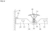
- FIG. 8 is a perspective view showing another exemplary embodiment of fixing a finishing panel of the ceiling finishing panel fixing device shown in FIG. 2 to a wall
- FIG. 9 is a partial exploded perspective view showing the ceiling finishing panel fixing device according to another exemplary embodiment of the present invention
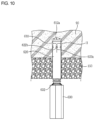
- FIGS. 10 and 11 are cross-sectional views showing a use state of the present invention
- FIG. 12 is a plan view showing a tightening member according to the exemplary embodiment of the present invention
- FIG. 13 is a plan view showing a reinforcing pipe according to the exemplary embodiment of the present invention
- FIG. 14 is a photograph of a hammer drill for forming an installation hole in a ceiling slab in order to fix an anchor bolt assembly to a ceiling according to the exemplary embodiment of the present invention.
- the ceiling finishing panel fixing device includes: a finishing panel 200, a channel bar 300, a panel fixing bar 400, and an anchor bolt assembly 600.
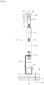
- the anchor bolt assembly 600 has an upper part thereof fixed to a ceiling slab and has a lower part thereof coupled to the channel bar 300 to be described later, and is provided with an anchor body 610 (aka, anchor bolt), an anchor shell 620, a tightening member 630, a full-threaded bolt 660, a reinforcing pipe 670, and a hanger 680.
- an anchor body 610 aka, anchor bolt
- an anchor shell 620 aka, an anchor shell 620
- a tightening member 630 a full-threaded bolt 660
- a reinforcing pipe 670 a hanger 680.
- a plurality of triangular pyramid-shaped protrusions 612a is provided on the upper surface of the anchor body 610, is integrated with the anchor body 610 at intervals of 90 degrees, and is formed at a predetermined height, so that the anchor body 610 does not rotate (i.e., so as not to spin in place with no traction) by contacting the interior of the installation hole (H in FIG. 10 ) of the ceiling slab during installation. Accordingly, when the tightening member 630 to be described later is tightened, the protrusion 612a is embedded in the deepest part of the installation hole H of the ceiling slab, thereby preventing the rotation (i.e., a phenomenon of spinning in place with no traction) of the anchor body 610.
- the protrusion 612a is shown to have a triangular pyramid shape, but the present invention is not limited thereto, and a protrusion may be used as long as the protrusion has a shape of a pointed tip.
- a double steppedjaw612b having a " ⁇ >" (angle brackets) shaped side thereof is provided as an outer diameter thereof widens downward from an upper end of the anchor body 610 provided with the protrusion 612a and then narrows downward again.
- a screw thread for screwing with the tightening member 630 is formed on the lower part of the double stepped jaw 612b, that is, on the outer circumferential surface of a trunk part of the anchor body 610.
- a double screw thread 614 is formed at a predetermined height from the lower end of the anchor body 610 toward the upper side thereof, so that even when the tightening member 630 is allowed to be rotated less, tightening or loosening action is done by means of the double screw thread 614, thereby reducing installation time.
- the anchor shell 620 is a part having open upper and lower sides thereof, is extrapolated to the lower side of the anchor body 610, and is configured such that first incised parts 622a having a "Y" shape are formed at equal intervals along the circumference of the anchor shell 620, and a plurality of second incised parts 622b having a "v" shape is formed at equal intervals along the longitudinal direction of the first incised parts 622a so that the plurality of expansion pieces 622 are separated from each other.
- each expansion piece 622 is configured to be separated from each other at a predetermined interval by the first incised part 622a and second incised part 622b, so that each expansion piece 622 is opened as the double stepped jaw 612b of the anchor body 610 is inserted into the inner side of the anchor shell 620 by the tightening action of the tightening member 630.
- each first incised part 622a of the anchor shell 620 is opened in the " ⁇ >" shape to the left and right due to the " ⁇ >" shape structure of the double stepped jaw 612b of the anchor body 610 and the " ⁇ " (circumflex symbol) shape structure of the deepest part of the installation hole H, and in this case, each second incised part 622b of the anchor shell 620 positioned on a side of a wall of the installation hole H has the same shape as a barb, and each barb-shaped part is drilled into the wall of the installation hole H, whereby the anchor shell 620 is strongly fixed to the wall.
- the " ⁇ " shape structure at the deepest part of the installation hole H is thus formed due to the " ⁇ " shape of a tip protrusion 810 formed in the center of the tip of a hammer drill 800 for forming an installation hole H.
- the anchor bolt assembly may be easily fixed to a ceiling slab, installation time is also reduced, and after the installation, the anchor bolt assembly may be prevented from falling out of the ceiling slab by vibration and the like.
- an upper end of the anchor body 610 is embedded in the ceiling slab 90 by protrusions 612a on the upper end of the anchor body 610, so that when rotating a tightening member 630 to the right with an impact drill (not shown) while pressing the tightening member 630 screwed to the lower side of the anchor body 610, the anchor body 610 is not rotated, but only the anchor shell 620 is opened while the anchor shell 620 is tightened by the tightening member 630, whereby the anchor body 610 and the anchor shell 620 are fixed to the ceiling slab 90.
- the tightening member 630 is generally in the form of a nut and is screwed to the anchor body 610 through a screwthread provided on the inner circumferential surface thereof, and is provided with a processing part 632 formed along a circumference of the upper part of the tightening member 630 in order to increase frictional force. That is, when the tightening member 630 rotates and approaches an installation hole H of the ceiling slab 90, the processing part 632 having an uneven shape closely adheres to the opening of the installation hole H, thereby preventing the lower part of the anchor body 610 from shaking.
- the processing part 632 may be configured to have a tooth shape of a knurling or a straight bevel gear.
- the full-threaded bolt 660 has a screw thread formed on the entire outer circumferential surface of the bolt having no head part.
- the upper side of such a full-threaded bolt 660 is screwed to a lower side of the tightening member 630, and a lower side of the anchor body 610 is screwed to an upper side of the tightening member 630.
- the reinforcing pipe 670 having a square pipe shape is opened at the top and bottom thereof and surrounds the outer side of a full-threaded bolt 660, in particular, the full-threaded bolt 660 having a long length, thereby preventing the full-threaded bolt 660 from bending.
- the hanger 680 is screwed to the lower side of the full-threaded bolt 660 by a pair of upper and lower nuts 640 provided in a horizontal bent part of the upper end of the hanger 680, and a lower end part of the hanger 680 is bent in double in the form of a "L"-shaped cross section, thereby being coupled to a channel bar 300 to be described later.
- the double bent part of the hanger 680 is provided with a hanger pin 682 inserted horizontally to hold the double bent part, and the channel bar 300 in the form of a "C" shape is combined between the hanger pin 682 and the hanger 680.
- each of the channel bars 300 is arranged long at a regular interval along a single direction on the upper part of each panel fixing bar 400, and is combined to the panel fixing bar 400, so as not to be removed, by a locking clip 420 having opposite ends thereof locked to the panel fixing bar 400.
- the part in which the channel bar 300, the panel fixing bar 400, and the locking clip 420 contact is combined with a screw bolt 710, whereby in the case where the locking clip 420 is removed, the panel fixing bar 400 is prevented from being separated from the channel bar 300.
- a cushioning material 684 is attached to the inside of the hanger 680 to prevent vibration of the hanger from being transmitted to the upper part of the anchor body 610 through other parts.
- the panel fixing bar 400 has a substantially inverted triangle shape, wherein left and right vertices of the upper part of the panel fixing bar 400 respectively have outer edges bent downward in a state where each of the left and right vertices is folded in two layers, so that each bent part of the outer edge is locked by each of the opposite ends of the locking clip 420.
- vertex parts having a concave-convex shape at the bottom center of the panel fixing bar 400 are in contact with each other, so that a fitting protrusion 220 formed at each end of adjacent finishing panels 200 is inserted into a position between the vertex parts having the concave-convex shape.
- a magnet 720 is placed at (i.e., attached to) a lower part of the screw bolt 710, thereby covering the head part of the screw bolt 710. In this way, it is possible to disassemble and install the finishing panel 200 when replacing a finishing panel 200 easier than when using a conventional cover.
- the exterior aesthetic of the ceiling finished with the finishing panel is also improved.
- the panel fixing bar 400 is arranged long at a right angle with respect to the channel bar under the channel bar 300 and is coupled to the channel bar 300 through the locking clip 420 as described above.
- a joint 430 having the same shape as the panel fixing bar, that is, an inverted triangle shape, may be further provided on the inside of the panel fixing bar.
- the finishing panel 200 attached to the panel fixing bar 400 is made of a non-combustible iron plate, an aluminum plate, a thermosetting resin plate, or a PVC-based plate, wherein protrusions 210 are formed upwardly at a predetermined height on both front and rear sides of the finishing panel 200, and fitting protrusions 220 are formed upwardly on both left and right sides of the finishing panel 200.
- the fitting protrusion 220 of the finishing panel 200 has a thick upper part so as not to fall out while being inserted into the position between the vertex parts of the bottom center of the panel fixing bar 400.
- the protrusion 210 is tapered toward the end thereof, so that half grooves 214 in which the panel fixing bar 400 is positioned are formed at left and right ends of the protrusion 210, and one half groove 214 together with the other half groove of an adjacent finishing panel 200 completely form a groove.
- Each locking hole 212 with a long length is provided in the protrusion 210, so that one end of a locking clip 410 is locked in a locking hole 212 of one finishing panel 200 in a state where the panel fixed bar 400 is placed on the groove between the adjacent finishing panels 200, and the other end of the locking clip 410 diagonally crosses the upper part of the panel fixing bar 400 and is locked in a locking hole 212 of the other finish panel 200, whereby the finishing panel 200 is attached to the panel fixing bar 400, and accordingly, the locking clip 410 is not exposed at the lower part of the finishing panel 200.
- a sound-absorbing material 500 having an insulating material or a sound-absorbing groove 502 formed therein may be coupled to the upper part of the finishing panel 200.
- the insulating material or sound-absorbing material 500 may be made in a plate shape by combining pulp or nonwoven fabric with recycled paper.
- a side end of the finishing panel 200 positioned at the outermost side thereof is fixed to one side wall, and the finishing panel 200 is forwardly fixed to the other side wall by using the above-described device and method.
- finishing panel 200 In the case of reaching the other side wall, when the finishing panel 200 adequately contacts the other side wall, there is no problem, but when the finishing panel 200 manufactured collectively in a predetermined size does not contact the other side wall, the finishing panel 200 must be cut partially and fixed to the other side wall.
- a "C"-shaped molding 130 made of aluminum, PVC, or iron is attached to the wall, and a cut finishing panel 200 is placed on the bottom of the "C"-shaped molding 130, wherein a hold-down clip 140 which is PVC-based and elastic is used and pressed from above to prevent the cut finishing panel 200 from moving.
- a slit 142 in FIG. 7 is formed in the hold-down clip 140 to stably press the finishing panel 200 in a state of being fitted on the upper part of the "C"-shaped molding 130.
- the "C"-shaped molding 130 made of aluminum is attached to the wall 120 and the finishing panel 200 is inserted into the "C"-shaped molding 130.
- a screw bolt 710 passes through the panel fixing bar 400, and then a magnet 720 is attached to the screw bolt 710.
- an insulation material 150 made of Styrofoam material is installed at a lower part of a ceiling slab 90 made of concrete
- installation work is performed by fitting an anchor shell 620 longer than the thickness of the insulation material 150 into an anchor body 610 and tightening a tightening member 630.
- an anchor bolt assembly 600 made of a material that does not rust is used for the ceiling of an indoor swimming pool, bath, or sauna, which are continuously exposed to moisture.
- the improved anchor bolt assembly and the ceiling finishing panel fixing device including the same according to the present invention is necessary for shielding a rough ceiling surface such as concrete, or for heat insulating the interior of a building, or for finishing a ceiling so that the electric wiring and the like installed on the ceiling is not exposed, and thus the present invention has industrial applicability.
Landscapes
- Engineering & Computer Science (AREA)
- Architecture (AREA)
- Physics & Mathematics (AREA)
- Electromagnetism (AREA)
- Civil Engineering (AREA)
- Structural Engineering (AREA)
- General Engineering & Computer Science (AREA)
- Mechanical Engineering (AREA)
- Joining Of Building Structures In Genera (AREA)
Claims (3)
- Ankerbolzenbaugruppe mit einem oberen Teil, der dazu ausgestaltet ist, an einer Deckenplatte befestigt zu werden, die ein Installationsloch umfasst, und einem unteren Teil, der dazu ausgestaltet ist, mit einer Kanalstange gekoppelt zu werden, wobei die Ankerbolzenbaugruppe Folgendes umfasst:einen Ankerkörper (610), der mit einer Mehrzahl von spitzen Vorsprüngen (612a) auf seiner oberen Oberfläche versehen ist;eine Ankerhülse (620), die mit einer offenen Ober- und Unterseite versehen ist, extrapoliert zu einer Unterseite des Ankerkörpers (610), die mit einem ersten eingeschnittenen Teil (622a) mit einer "Y"-Form in einem gleichen Abstand entlang eines Umfangs der Ankerhülse (620) versehen ist, undein Spannelement (630),wobei die Ankerbolzenbaugruppe dadurch gekennzeichnet ist, dassder Ankerkörper (610) mit einer doppelstufigen Backe (612b) versehen ist, die eine Seite mit einer Form von "spitzen Klammern" "<>" aufweist, während ein Außendurchmesser davon von einem oberen Ende des Ankerkörpers (610) nach unten breiter und dann wieder nach unten schmaler wird;die Ankerhülse (620) mit einem zweiten eingeschnittenen Teil (622b) mit einer "v"-Form in einem gleichen Abstand entlang einer Längsrichtung des ersten eingeschnittenen Teils versehen ist; und dassdas Spannelement (630) mit dem Ankerkörper (610) über ein Schraubgewinde verschraubt wird, das an einer inneren Umfangsfläche des Spannelementes (630) vorgesehen ist und das die doppelstufige Backe (612b) des Ankerkörpers (610) spannt und ermöglicht, dass diese in die Ankerhülse (620) eingeführt wird, um ein Spreizteil (622) zu spreizen, und mit einem Verarbeitungsteil (632) zum Erhöhen der Reibungskraft entlang eines Umfangs eines oberen Endes des Spannelementes (630) versehen ist,
und dasswenn die Ankerhülse (620) durch das Spannelement (630) in Richtung eines tiefsten Teils eines Installationslochs (H) angehoben wird, aufgrund einer Struktur der Form von "spitzen Klammern" "<>" der doppelstufigen Backe (612b) des Ankerkörpers (610) und einer Struktur der Form eines "Zirkumflex-Symbols" "^" des tiefsten Teils des Installationslochs (H) der erste eingeschnittene Teil (622a) der Ankerhülse (620) nach links und rechts in einer Form von "spitzen Klammern" "<>" geöffnet wird, so dass ein oberer Teil der Ankerhülse (620) in Richtung eines dreieckigen Pyramidenvorsprungs (612a) des Ankerkörpers (610) gebogen und gerafft wird,wobei gleichzeitig der zweite eingeschnittene Teil (622b) der Ankerhülse (620), der auf einer Wandseite des Installationslochs (H) angeordnet ist, die gleiche Form wie ein Widerhaken aufweist und dieser widerhakenförmige Teil in eine Wand des Installationslochs (H) gebohrt wird, wodurch die Ankerhülse (620) fest an der Wand fixiert wird. - Fixiervorrichtung einer Deckenverkleidungsplatte, die die Ankerbolzenbaugruppe nach Anspruch 1 umfasst und ferner Folgendes umfasst:einen Vollgewindebolzen (660), der auf seiner gesamten Außenumfangsfläche ein Schraubgewinde aufweist und mit seiner Oberseite an das Spannelement (630) der Ankerbolzenbaugruppe geschraubt ist;einen Aufhänger (680), der an eine Unterseite des Vollgewindebolzens (660) geschraubt ist;eine Kanalstange (300), die mit einer Stelle zwischen einem Aufhängebolzen (682) des Aufhängers (680) und dem Aufhänger (680) gekoppelt und in einem vorbestimmten Abstand entlang einer Richtung angeordnet ist;eine Plattenfixierstange (400), die an einem unteren Teil der Kanalstange (300) in einem rechten Winkel in Bezug auf die Kanalstange angeordnet und mit der Kanalstange (300) über eine Verschlussklemme (420) gekoppelt ist; undeine Verkleidungsplatte (200) mit Vorsprüngen (210), die in einer vorbestimmten Höhe sowohl von der Vorder- als auch von der Rückseite zu einer Oberseite der Verkleidungsplatte (200) ausgebildet sind, mit Passvorsprüngen (220), die von der linken und der rechten Seite davon zur Oberseite der Verkleidungsplatte (200) vorgesehen sind, und die an der Plattenfixierstange (400) angebracht ist, um eine Deckenfläche abzuschirmen.
- Fixiervorrichtung einer Deckenverkleidungsplatte nach Anspruch 2, wobei ein Schraubenbolzen (710) durch die Plattenfixierstange (400) hindurch zwischen der Verkleidungsplatte (200) und der benachbarten Verkleidungsplatte (200) befestigt ist und ein Magnet (720) an einem Kopfteil des Schraubenbolzens (710) angebracht ist.
Applications Claiming Priority (2)
| Application Number | Priority Date | Filing Date | Title |
|---|---|---|---|
| KR1020190050787A KR102132677B1 (ko) | 2018-10-10 | 2019-04-30 | 개선된 앵커볼트 조립체 및 이를 포함하는 천장 마감패널 고정장치 |
| PCT/KR2020/005687 WO2020222535A1 (ko) | 2019-04-30 | 2020-04-29 | 개선된 앵커볼트 조립체 및 이를 포함하는 천장 마감패널 고정장치 |
Publications (3)
| Publication Number | Publication Date |
|---|---|
| EP3964660A1 EP3964660A1 (de) | 2022-03-09 |
| EP3964660A4 EP3964660A4 (de) | 2023-01-25 |
| EP3964660B1 true EP3964660B1 (de) | 2024-07-17 |
Family
ID=73029751
Family Applications (1)
| Application Number | Title | Priority Date | Filing Date |
|---|---|---|---|
| EP20798927.8A Active EP3964660B1 (de) | 2019-04-30 | 2020-04-29 | Verbesserte ankerbolzenbaugruppe und fixiervorrichtung einer deckenverkleidungsplatte damit |
Country Status (5)
| Country | Link |
|---|---|
| US (1) | US11987980B2 (de) |
| EP (1) | EP3964660B1 (de) |
| JP (1) | JP7038920B2 (de) |
| CN (1) | CN112204200B (de) |
| WO (1) | WO2020222535A1 (de) |
Families Citing this family (2)
| Publication number | Priority date | Publication date | Assignee | Title |
|---|---|---|---|---|
| CN115262849B (zh) * | 2022-08-12 | 2023-08-18 | 广州市第一装修有限公司 | 一种木纹石膏天花板的饰板安装结构及安装方法 |
| CN117230926B (zh) * | 2023-11-10 | 2024-02-27 | 中国建筑一局(集团)有限公司 | 一种装配式铝扣板吊顶及其施工方法 |
Family Cites Families (32)
| Publication number | Priority date | Publication date | Assignee | Title |
|---|---|---|---|---|
| DE19507058A1 (de) * | 1995-01-28 | 1996-08-01 | Heinrich Liebig | Formschlüssig setzbarer Hinterschnitt-Anker |
| PT1275860E (pt) | 2001-07-12 | 2004-06-30 | Fischer Artur Werke Gmbh | Bucha expansivel para fixacao de materiais de construcao ocos ou macicos |
| US7287733B2 (en) * | 2002-05-14 | 2007-10-30 | Sullivan, Bazinet, Bongio, Inc. | Ceiling suspension structure |
| DE20303557U1 (de) * | 2003-03-06 | 2003-07-24 | Hlubek, Mavek, 83512 Wasserburg | Express-Hülsenanker |
| KR200385156Y1 (ko) | 2005-03-14 | 2005-05-24 | 김용길 | 앵커 볼트의 고정장치 |
| DE102006053226A1 (de) * | 2006-11-11 | 2008-05-15 | Fischerwerke Artur Fischer Gmbh & Co. Kg | Spreizdübel mit in axialer Richtung nachgiebiger Hülse |
| JP4294694B2 (ja) | 2007-01-29 | 2009-07-15 | 株式会社ケー・エフ・シー | ボルト接続用ナットおよびそれを用いたアンカー施工方法 |
| CN100497887C (zh) * | 2007-06-19 | 2009-06-10 | 郑晓雯 | 套管涨壳型自钻式中空锚杆 |
| CN101655120A (zh) * | 2008-08-20 | 2010-02-24 | 兴化华康不锈钢制品有限公司 | 膨胀组合件 |
| CN201513451U (zh) * | 2009-09-23 | 2010-06-23 | 伊玛精密电子(苏州)有限公司 | 膨胀螺母 |
| DE102009045345A1 (de) * | 2009-10-06 | 2011-04-07 | Hilti Aktiengesellschaft | Spreizdübel |
| KR101051265B1 (ko) * | 2010-10-26 | 2011-07-21 | 기세진 | 셋트 앵커볼트의 슬리브 성형방법 및 그 제품 |
| CN202326581U (zh) * | 2011-11-04 | 2012-07-11 | 沈一军 | 一种自攻膨胀螺栓 |
| US8905697B2 (en) * | 2012-04-23 | 2014-12-09 | Illinois Tool Works Inc. | Thermal break fastener |
| US8690222B2 (en) * | 2012-05-25 | 2014-04-08 | Winfield Consumer Products, Inc. | Vehicle floor mat or floor liner kit having a clip |
| US8661766B2 (en) * | 2012-06-22 | 2014-03-04 | Mitek Holdings, Inc. | Anchor with angular adjustment |
| US9260857B2 (en) * | 2013-03-14 | 2016-02-16 | Columbia Insurance Company | Fail-safe anchoring systems for cavity walls |
| CN103204302B (zh) * | 2013-04-24 | 2015-07-22 | 广东华恒盛重包装集团有限公司 | 一种子母扣件 |
| US20150121792A1 (en) * | 2013-11-06 | 2015-05-07 | Owens Corning Intellectual Capital, Llc | Composite thermal isolating masonry tie fastener |
| CN104110423B (zh) * | 2014-03-13 | 2017-11-17 | 徐发煌 | 槽折膨胀螺栓 |
| CN204458717U (zh) * | 2015-01-20 | 2015-07-08 | 山东陶氏新材料有限公司 | 一种保温外墙锚固件 |
| US10781844B2 (en) * | 2015-11-02 | 2020-09-22 | Lee Kunken | Substrate anchoring device |
| KR101617779B1 (ko) * | 2015-11-20 | 2016-05-03 | 차주병 | 천장 마감패널 고정장치 |
| US20170159285A1 (en) * | 2015-12-04 | 2017-06-08 | Columbia Insurance Company | Thermal wall anchor |
| US9945414B1 (en) * | 2016-01-08 | 2018-04-17 | Rodenhouse, Inc. | Thermal break washer system and method for building construction |
| KR101845007B1 (ko) * | 2016-02-24 | 2018-04-04 | 대천볼트(주) | 앵커볼트 조립체 |
| KR101823555B1 (ko) * | 2016-03-09 | 2018-01-30 | 차주병 | 천장 마감패널 고정장치 |
| CN205689543U (zh) * | 2016-05-31 | 2016-11-16 | 温州君浩实业有限公司 | 新型六点式膨胀螺栓 |
| CN109538595A (zh) * | 2017-09-21 | 2019-03-29 | 贵港市厚顺信息技术有限公司 | 一种可拆卸的膨胀螺丝 |
| KR102132677B1 (ko) | 2018-10-10 | 2020-07-13 | 차주병 | 개선된 앵커볼트 조립체 및 이를 포함하는 천장 마감패널 고정장치 |
| US11698095B1 (en) * | 2019-04-25 | 2023-07-11 | Altenloh, Brinck & Co. Us, Inc. | Wall system fastener with seal member |
| US10968638B1 (en) * | 2020-01-16 | 2021-04-06 | Ronald Hohmann, Jr. | Systems and methods for an insulated thermal wall anchor |
-
2020
- 2020-04-29 WO PCT/KR2020/005687 patent/WO2020222535A1/ko not_active Ceased
- 2020-04-29 JP JP2021539324A patent/JP7038920B2/ja active Active
- 2020-04-29 US US17/291,439 patent/US11987980B2/en active Active
- 2020-04-29 EP EP20798927.8A patent/EP3964660B1/de active Active
- 2020-04-29 CN CN202080001776.9A patent/CN112204200B/zh active Active
Also Published As
| Publication number | Publication date |
|---|---|
| CN112204200A (zh) | 2021-01-08 |
| US20220002995A1 (en) | 2022-01-06 |
| EP3964660A4 (de) | 2023-01-25 |
| CN112204200B (zh) | 2021-09-28 |
| JP7038920B2 (ja) | 2022-03-18 |
| US11987980B2 (en) | 2024-05-21 |
| JP2021535973A (ja) | 2021-12-23 |
| WO2020222535A1 (ko) | 2020-11-05 |
| EP3964660A1 (de) | 2022-03-09 |
Similar Documents
| Publication | Publication Date | Title |
|---|---|---|
| KR101784263B1 (ko) | 건축용 석재고정 앙카 지지구 | |
| US11725683B2 (en) | Multi-featured panel fastener and panel system including the multi-featured panel fastener | |
| EP3964660B1 (de) | Verbesserte ankerbolzenbaugruppe und fixiervorrichtung einer deckenverkleidungsplatte damit | |
| KR102132677B1 (ko) | 개선된 앵커볼트 조립체 및 이를 포함하는 천장 마감패널 고정장치 | |
| US5727355A (en) | Stone facing section anchor mounting system | |
| KR101492594B1 (ko) | 마감재 지지앵커 시공장치, 마감재 지지앵커 시공방법 및 마감재 지지앵커 | |
| CN215907032U (zh) | 一种建筑墙板之间固定连接结构 | |
| KR200385716Y1 (ko) | 건축물의 외장패널 코너고정장치 | |
| KR0172037B1 (ko) | 커튼월용 외벽판재의 고정구 | |
| KR100961434B1 (ko) | 자연석의 체결 구조 | |
| KR200388922Y1 (ko) | 건축물의 외장패널 고정장치 | |
| KR20070072357A (ko) | 건축물의 외장패널 고정장치 | |
| JP3231509B2 (ja) | 化粧パネル取付構造 | |
| HK40041239A (en) | Improved anchor bolt assembly and ceiling finishing panel fixing device comprising same | |
| HK40041239B (en) | Improved anchor bolt assembly and ceiling finishing panel fixing device comprising same | |
| KR101057832B1 (ko) | 건축 외장재용 고정장치 | |
| KR20190002896U (ko) | 천장용 세트앵커 | |
| KR200317808Y1 (ko) | 노출 콘크리트 패널 고정구 | |
| KR100661050B1 (ko) | 건축물의 외장패널 고정장치 | |
| KR20190038025A (ko) | 결속력을 상승시킨 건축용 앵커 어셈블리 | |
| JPH0339533Y2 (de) | ||
| KR200403580Y1 (ko) | 박막의 고정재에도 사용할 수 있도록 된 자가천공나사 | |
| KR200140850Y1 (ko) | 걸림수단이 부설된 고정구 | |
| KR20200118691A (ko) | 플랫가이드부를 갖는 패널 장착용 체결구 | |
| KR20100065751A (ko) | 구조물의 기둥 구조 |
Legal Events
| Date | Code | Title | Description |
|---|---|---|---|
| STAA | Information on the status of an ep patent application or granted ep patent |
Free format text: STATUS: THE INTERNATIONAL PUBLICATION HAS BEEN MADE |
|
| PUAI | Public reference made under article 153(3) epc to a published international application that has entered the european phase |
Free format text: ORIGINAL CODE: 0009012 |
|
| STAA | Information on the status of an ep patent application or granted ep patent |
Free format text: STATUS: REQUEST FOR EXAMINATION WAS MADE |
|
| 17P | Request for examination filed |
Effective date: 20211118 |
|
| AK | Designated contracting states |
Kind code of ref document: A1 Designated state(s): AL AT BE BG CH CY CZ DE DK EE ES FI FR GB GR HR HU IE IS IT LI LT LU LV MC MK MT NL NO PL PT RO RS SE SI SK SM TR |
|
| DAV | Request for validation of the european patent (deleted) | ||
| DAX | Request for extension of the european patent (deleted) | ||
| A4 | Supplementary search report drawn up and despatched |
Effective date: 20230104 |
|
| RIC1 | Information provided on ipc code assigned before grant |
Ipc: E04B 9/00 20060101ALI20221222BHEP Ipc: E04B 9/18 20060101ALI20221222BHEP Ipc: E04B 1/41 20060101AFI20221222BHEP |
|
| R17P | Request for examination filed (corrected) |
Effective date: 20211118 |
|
| GRAP | Despatch of communication of intention to grant a patent |
Free format text: ORIGINAL CODE: EPIDOSNIGR1 |
|
| STAA | Information on the status of an ep patent application or granted ep patent |
Free format text: STATUS: GRANT OF PATENT IS INTENDED |
|
| INTG | Intention to grant announced |
Effective date: 20240213 |
|
| GRAS | Grant fee paid |
Free format text: ORIGINAL CODE: EPIDOSNIGR3 |
|
| GRAA | (expected) grant |
Free format text: ORIGINAL CODE: 0009210 |
|
| STAA | Information on the status of an ep patent application or granted ep patent |
Free format text: STATUS: THE PATENT HAS BEEN GRANTED |
|
| AK | Designated contracting states |
Kind code of ref document: B1 Designated state(s): AL AT BE BG CH CY CZ DE DK EE ES FI FR GB GR HR HU IE IS IT LI LT LU LV MC MK MT NL NO PL PT RO RS SE SI SK SM TR |
|
| REG | Reference to a national code |
Ref country code: CH Ref legal event code: EP |
|
| REG | Reference to a national code |
Ref country code: DE Ref legal event code: R096 Ref document number: 602020034206 Country of ref document: DE |
|
| REG | Reference to a national code |
Ref country code: IE Ref legal event code: FG4D |
|
| REG | Reference to a national code |
Ref country code: LT Ref legal event code: MG9D |
|
| REG | Reference to a national code |
Ref country code: NL Ref legal event code: MP Effective date: 20240717 |
|
| PG25 | Lapsed in a contracting state [announced via postgrant information from national office to epo] |
Ref country code: PT Free format text: LAPSE BECAUSE OF FAILURE TO SUBMIT A TRANSLATION OF THE DESCRIPTION OR TO PAY THE FEE WITHIN THE PRESCRIBED TIME-LIMIT Effective date: 20241118 |
|
| REG | Reference to a national code |
Ref country code: AT Ref legal event code: MK05 Ref document number: 1704265 Country of ref document: AT Kind code of ref document: T Effective date: 20240717 |
|
| PG25 | Lapsed in a contracting state [announced via postgrant information from national office to epo] |
Ref country code: NL Free format text: LAPSE BECAUSE OF FAILURE TO SUBMIT A TRANSLATION OF THE DESCRIPTION OR TO PAY THE FEE WITHIN THE PRESCRIBED TIME-LIMIT Effective date: 20240717 |
|
| PG25 | Lapsed in a contracting state [announced via postgrant information from national office to epo] |
Ref country code: PT Free format text: LAPSE BECAUSE OF FAILURE TO SUBMIT A TRANSLATION OF THE DESCRIPTION OR TO PAY THE FEE WITHIN THE PRESCRIBED TIME-LIMIT Effective date: 20241118 Ref country code: NL Free format text: LAPSE BECAUSE OF FAILURE TO SUBMIT A TRANSLATION OF THE DESCRIPTION OR TO PAY THE FEE WITHIN THE PRESCRIBED TIME-LIMIT Effective date: 20240717 |
|
| PG25 | Lapsed in a contracting state [announced via postgrant information from national office to epo] |
Ref country code: NO Free format text: LAPSE BECAUSE OF FAILURE TO SUBMIT A TRANSLATION OF THE DESCRIPTION OR TO PAY THE FEE WITHIN THE PRESCRIBED TIME-LIMIT Effective date: 20241017 |
|
| PG25 | Lapsed in a contracting state [announced via postgrant information from national office to epo] |
Ref country code: PL Free format text: LAPSE BECAUSE OF FAILURE TO SUBMIT A TRANSLATION OF THE DESCRIPTION OR TO PAY THE FEE WITHIN THE PRESCRIBED TIME-LIMIT Effective date: 20240717 Ref country code: GR Free format text: LAPSE BECAUSE OF FAILURE TO SUBMIT A TRANSLATION OF THE DESCRIPTION OR TO PAY THE FEE WITHIN THE PRESCRIBED TIME-LIMIT Effective date: 20241018 Ref country code: FI Free format text: LAPSE BECAUSE OF FAILURE TO SUBMIT A TRANSLATION OF THE DESCRIPTION OR TO PAY THE FEE WITHIN THE PRESCRIBED TIME-LIMIT Effective date: 20240717 |
|
| PG25 | Lapsed in a contracting state [announced via postgrant information from national office to epo] |
Ref country code: BG Free format text: LAPSE BECAUSE OF FAILURE TO SUBMIT A TRANSLATION OF THE DESCRIPTION OR TO PAY THE FEE WITHIN THE PRESCRIBED TIME-LIMIT Effective date: 20240717 |
|
| PG25 | Lapsed in a contracting state [announced via postgrant information from national office to epo] |
Ref country code: LV Free format text: LAPSE BECAUSE OF FAILURE TO SUBMIT A TRANSLATION OF THE DESCRIPTION OR TO PAY THE FEE WITHIN THE PRESCRIBED TIME-LIMIT Effective date: 20240717 |
|
| PG25 | Lapsed in a contracting state [announced via postgrant information from national office to epo] |
Ref country code: IS Free format text: LAPSE BECAUSE OF FAILURE TO SUBMIT A TRANSLATION OF THE DESCRIPTION OR TO PAY THE FEE WITHIN THE PRESCRIBED TIME-LIMIT Effective date: 20241117 Ref country code: AT Free format text: LAPSE BECAUSE OF FAILURE TO SUBMIT A TRANSLATION OF THE DESCRIPTION OR TO PAY THE FEE WITHIN THE PRESCRIBED TIME-LIMIT Effective date: 20240717 |
|
| PG25 | Lapsed in a contracting state [announced via postgrant information from national office to epo] |
Ref country code: HR Free format text: LAPSE BECAUSE OF FAILURE TO SUBMIT A TRANSLATION OF THE DESCRIPTION OR TO PAY THE FEE WITHIN THE PRESCRIBED TIME-LIMIT Effective date: 20240717 |
|
| PG25 | Lapsed in a contracting state [announced via postgrant information from national office to epo] |
Ref country code: ES Free format text: LAPSE BECAUSE OF FAILURE TO SUBMIT A TRANSLATION OF THE DESCRIPTION OR TO PAY THE FEE WITHIN THE PRESCRIBED TIME-LIMIT Effective date: 20240717 Ref country code: RS Free format text: LAPSE BECAUSE OF FAILURE TO SUBMIT A TRANSLATION OF THE DESCRIPTION OR TO PAY THE FEE WITHIN THE PRESCRIBED TIME-LIMIT Effective date: 20241017 |
|
| PG25 | Lapsed in a contracting state [announced via postgrant information from national office to epo] |
Ref country code: RS Free format text: LAPSE BECAUSE OF FAILURE TO SUBMIT A TRANSLATION OF THE DESCRIPTION OR TO PAY THE FEE WITHIN THE PRESCRIBED TIME-LIMIT Effective date: 20241017 Ref country code: PL Free format text: LAPSE BECAUSE OF FAILURE TO SUBMIT A TRANSLATION OF THE DESCRIPTION OR TO PAY THE FEE WITHIN THE PRESCRIBED TIME-LIMIT Effective date: 20240717 Ref country code: NO Free format text: LAPSE BECAUSE OF FAILURE TO SUBMIT A TRANSLATION OF THE DESCRIPTION OR TO PAY THE FEE WITHIN THE PRESCRIBED TIME-LIMIT Effective date: 20241017 Ref country code: LV Free format text: LAPSE BECAUSE OF FAILURE TO SUBMIT A TRANSLATION OF THE DESCRIPTION OR TO PAY THE FEE WITHIN THE PRESCRIBED TIME-LIMIT Effective date: 20240717 Ref country code: IS Free format text: LAPSE BECAUSE OF FAILURE TO SUBMIT A TRANSLATION OF THE DESCRIPTION OR TO PAY THE FEE WITHIN THE PRESCRIBED TIME-LIMIT Effective date: 20241117 Ref country code: HR Free format text: LAPSE BECAUSE OF FAILURE TO SUBMIT A TRANSLATION OF THE DESCRIPTION OR TO PAY THE FEE WITHIN THE PRESCRIBED TIME-LIMIT Effective date: 20240717 Ref country code: GR Free format text: LAPSE BECAUSE OF FAILURE TO SUBMIT A TRANSLATION OF THE DESCRIPTION OR TO PAY THE FEE WITHIN THE PRESCRIBED TIME-LIMIT Effective date: 20241018 Ref country code: FI Free format text: LAPSE BECAUSE OF FAILURE TO SUBMIT A TRANSLATION OF THE DESCRIPTION OR TO PAY THE FEE WITHIN THE PRESCRIBED TIME-LIMIT Effective date: 20240717 Ref country code: ES Free format text: LAPSE BECAUSE OF FAILURE TO SUBMIT A TRANSLATION OF THE DESCRIPTION OR TO PAY THE FEE WITHIN THE PRESCRIBED TIME-LIMIT Effective date: 20240717 Ref country code: BG Free format text: LAPSE BECAUSE OF FAILURE TO SUBMIT A TRANSLATION OF THE DESCRIPTION OR TO PAY THE FEE WITHIN THE PRESCRIBED TIME-LIMIT Effective date: 20240717 Ref country code: AT Free format text: LAPSE BECAUSE OF FAILURE TO SUBMIT A TRANSLATION OF THE DESCRIPTION OR TO PAY THE FEE WITHIN THE PRESCRIBED TIME-LIMIT Effective date: 20240717 |
|
| PG25 | Lapsed in a contracting state [announced via postgrant information from national office to epo] |
Ref country code: DK Free format text: LAPSE BECAUSE OF FAILURE TO SUBMIT A TRANSLATION OF THE DESCRIPTION OR TO PAY THE FEE WITHIN THE PRESCRIBED TIME-LIMIT Effective date: 20240717 Ref country code: SM Free format text: LAPSE BECAUSE OF FAILURE TO SUBMIT A TRANSLATION OF THE DESCRIPTION OR TO PAY THE FEE WITHIN THE PRESCRIBED TIME-LIMIT Effective date: 20240717 Ref country code: RO Free format text: LAPSE BECAUSE OF FAILURE TO SUBMIT A TRANSLATION OF THE DESCRIPTION OR TO PAY THE FEE WITHIN THE PRESCRIBED TIME-LIMIT Effective date: 20240717 |
|
| REG | Reference to a national code |
Ref country code: DE Ref legal event code: R097 Ref document number: 602020034206 Country of ref document: DE |
|
| PG25 | Lapsed in a contracting state [announced via postgrant information from national office to epo] |
Ref country code: EE Free format text: LAPSE BECAUSE OF FAILURE TO SUBMIT A TRANSLATION OF THE DESCRIPTION OR TO PAY THE FEE WITHIN THE PRESCRIBED TIME-LIMIT Effective date: 20240717 |
|
| PG25 | Lapsed in a contracting state [announced via postgrant information from national office to epo] |
Ref country code: CZ Free format text: LAPSE BECAUSE OF FAILURE TO SUBMIT A TRANSLATION OF THE DESCRIPTION OR TO PAY THE FEE WITHIN THE PRESCRIBED TIME-LIMIT Effective date: 20240717 |
|
| PG25 | Lapsed in a contracting state [announced via postgrant information from national office to epo] |
Ref country code: SK Free format text: LAPSE BECAUSE OF FAILURE TO SUBMIT A TRANSLATION OF THE DESCRIPTION OR TO PAY THE FEE WITHIN THE PRESCRIBED TIME-LIMIT Effective date: 20240717 |
|
| PLBE | No opposition filed within time limit |
Free format text: ORIGINAL CODE: 0009261 |
|
| STAA | Information on the status of an ep patent application or granted ep patent |
Free format text: STATUS: NO OPPOSITION FILED WITHIN TIME LIMIT |
|
| 26N | No opposition filed |
Effective date: 20250422 |
|
| PGFP | Annual fee paid to national office [announced via postgrant information from national office to epo] |
Ref country code: DE Payment date: 20250414 Year of fee payment: 6 |
|
| PGFP | Annual fee paid to national office [announced via postgrant information from national office to epo] |
Ref country code: GB Payment date: 20250423 Year of fee payment: 6 |
|
| PGFP | Annual fee paid to national office [announced via postgrant information from national office to epo] |
Ref country code: FR Payment date: 20250422 Year of fee payment: 6 |
|
| PG25 | Lapsed in a contracting state [announced via postgrant information from national office to epo] |
Ref country code: SE Free format text: LAPSE BECAUSE OF FAILURE TO SUBMIT A TRANSLATION OF THE DESCRIPTION OR TO PAY THE FEE WITHIN THE PRESCRIBED TIME-LIMIT Effective date: 20240717 |
|
| REG | Reference to a national code |
Ref country code: CH Ref legal event code: H13 Free format text: ST27 STATUS EVENT CODE: U-0-0-H10-H13 (AS PROVIDED BY THE NATIONAL OFFICE) Effective date: 20251125 |
|
| PG25 | Lapsed in a contracting state [announced via postgrant information from national office to epo] |
Ref country code: LU Free format text: LAPSE BECAUSE OF NON-PAYMENT OF DUE FEES Effective date: 20250429 |
|
| PG25 | Lapsed in a contracting state [announced via postgrant information from national office to epo] |
Ref country code: MC Free format text: LAPSE BECAUSE OF FAILURE TO SUBMIT A TRANSLATION OF THE DESCRIPTION OR TO PAY THE FEE WITHIN THE PRESCRIBED TIME-LIMIT Effective date: 20240717 |
|
| REG | Reference to a national code |
Ref country code: BE Ref legal event code: MM Effective date: 20250430 |
|
| PG25 | Lapsed in a contracting state [announced via postgrant information from national office to epo] |
Ref country code: BE Free format text: LAPSE BECAUSE OF NON-PAYMENT OF DUE FEES Effective date: 20250430 |
|
| PG25 | Lapsed in a contracting state [announced via postgrant information from national office to epo] |
Ref country code: CH Free format text: LAPSE BECAUSE OF NON-PAYMENT OF DUE FEES Effective date: 20250430 |
|
| PG25 | Lapsed in a contracting state [announced via postgrant information from national office to epo] |
Ref country code: IT Free format text: LAPSE BECAUSE OF FAILURE TO SUBMIT A TRANSLATION OF THE DESCRIPTION OR TO PAY THE FEE WITHIN THE PRESCRIBED TIME-LIMIT Effective date: 20240717 |
|
| PG25 | Lapsed in a contracting state [announced via postgrant information from national office to epo] |
Ref country code: IE Free format text: LAPSE BECAUSE OF NON-PAYMENT OF DUE FEES Effective date: 20250429 |