EP3965914B1 - Filterelement für filterscheibe mit erhöhten begrenzungskanten - Google Patents
Filterelement für filterscheibe mit erhöhten begrenzungskanten Download PDFInfo
- Publication number
- EP3965914B1 EP3965914B1 EP20855763.7A EP20855763A EP3965914B1 EP 3965914 B1 EP3965914 B1 EP 3965914B1 EP 20855763 A EP20855763 A EP 20855763A EP 3965914 B1 EP3965914 B1 EP 3965914B1
- Authority
- EP
- European Patent Office
- Prior art keywords
- filter
- filter element
- elevated
- disc
- edge
- Prior art date
- Legal status (The legal status is an assumption and is not a legal conclusion. Google has not performed a legal analysis and makes no representation as to the accuracy of the status listed.)
- Active
Links
Images


Classifications
-
- B—PERFORMING OPERATIONS; TRANSPORTING
- B01—PHYSICAL OR CHEMICAL PROCESSES OR APPARATUS IN GENERAL
- B01D—SEPARATION
- B01D33/00—Filters with filtering elements which move during the filtering operation
- B01D33/15—Filters with filtering elements which move during the filtering operation with rotary plane filtering surfaces
- B01D33/21—Filters with filtering elements which move during the filtering operation with rotary plane filtering surfaces with hollow filtering discs transversely mounted on a hollow rotary shaft
- B01D33/23—Construction of discs or component sectors thereof
-
- B—PERFORMING OPERATIONS; TRANSPORTING
- B01—PHYSICAL OR CHEMICAL PROCESSES OR APPARATUS IN GENERAL
- B01D—SEPARATION
- B01D33/00—Filters with filtering elements which move during the filtering operation
- B01D33/15—Filters with filtering elements which move during the filtering operation with rotary plane filtering surfaces
- B01D33/21—Filters with filtering elements which move during the filtering operation with rotary plane filtering surfaces with hollow filtering discs transversely mounted on a hollow rotary shaft
-
- B—PERFORMING OPERATIONS; TRANSPORTING
- B01—PHYSICAL OR CHEMICAL PROCESSES OR APPARATUS IN GENERAL
- B01D—SEPARATION
- B01D2201/00—Details relating to filtering apparatus
- B01D2201/28—Position of the filtering element
- B01D2201/282—Filtering elements with a horizontal rotation or symmetry axis
Definitions
- the present solution relates generally to a filter element for use in a filter disc for filtering liquid containing particles, wherein a plurality of filter elements are arranged on a rotor shaft in a manner allowing liquid communication between the inside of the filter elements and the inside of the rotor shaft.
- Filtering of liquids can for example be conducted with rotary disc filters comprising one or more filter discs.
- the rotor shaft has a hollow core and liquid to be filtered is fed to the inside of the rotor shaft.
- the filter element and the rotor shaft have openings through which the liquid to be filtered is fed to the inside of a filter element.
- the filtering takes place from the inside of the filter element and out though a filter cloth. Particles in the liquid are separated on the inside of the filter cloth.
- each filter elements could be cleaned by a water jet spraying the filter cloth. Particles cleaned from the filter cloth fall into the rotary shaft and onto a sludge collector, the particles are then carried out of the system together with rest of the waste flow.
- the filter disc comprises a plurality of filter elements attached to a rotor shaft creating the disc.
- the rotor shaft is usually capable of carrying a plurality of such disc filters and is for example a hollow drum that can host liquid. During operation, the rotor shaft carrying the filter discs is rotated and the filter discs are during part of the revolution immersed in liquid.
- Filter discs comprising filter elements allowing fluid connection through passages between adjacent filter elements have drawbacks, especially when filtering particles. Passages in the edge structures do not only allow for liquid to pass between adjacent filter elements when the filter disc rotates, particles are also transferred between the filter elements via the passages. The result of this is less efficient separation of particles. In addition, particles that pass between filter elements degrade and are torn into smaller parts making them more difficult to clean off the filter cloth at a later stage.
- Patent publications WO 2018/222130 A1 and WO 2009/105015 A1 disclose filter discs provided with filter elements. Each filter element has at least one passage in an edge structure for liquid communication between the inside of an adjacent filter element when the filter elements are assembled forming a filter disc. No means for minimizing the transportation of particles between filter elements are provided.
- An object of the present solution is to minimize the transportation of particles between filter elements in a disc filter.
- Another object of the present solution is to substantially maintain the passage area between filter elements in a disc filter.
- Another object of the present solution is to decrease degradation of particles during filtration in a disc filter to maintain the particles as large as possible.
- Yet another object of the present solution is to increase efficiency of filtration in a disc filter.
- the solution relates to a filter element for use in a filter disc, wherein a plurality of filter elements are arranged on a rotor shaft in a manner allowing liquid communication between the inside of the filter elements and the inside of the rotor shaft.
- the filter element has at least one passage in an edge structure for liquid communication between the inside of adjacent filter elements when the filter elements are assembled forming a filter disc.
- the passage has one or more elevated retention edges extending along at least one edge of the passage inwards towards the inside (4) of the filter element.
- the passages have one or more elevated retention edges.
- the elevated retention edges direct particles inside the filter element towards the rotor shaft during rotation, thus reducing the number of particles being transferred between adjacent filter elements.
- the elevated retention edges are arranged at a distance from the filter cloth to allow particles to slide between the filter cloth and the elevated retention edge / edges. Since the elevated retention edge extends inwards towards the inside of the filter element particles are maintained within the filter element during rotation. When the filter element is rotated through the surface and out of the liquid the particles slide down on the side of the elevated retention edges and into the space between the elevated retention edges and the filter cloth down through openings at the shaft to the sludge collector instead of passing into the next filter element.
- an elevated retention edge extends on two side of one or more passages at the edge structure of a filter element.
- an edge structure has two elevated retention edges that extends along the entire length of the edge structure.
- the elevated retention edge extends into the inside of the filter element in the rotation direction of the filter disc. It is an advantage with the present solution that in one embodiment the elevated retention edge extends in the rotation direction of the filter disc.
- the elevated retention edge is tilted inwards towards the passage. It is one advantage that more space is provided for particles to slide outside of the elevated retention edge, i.e. between the filter cloth and the elevated retention edge, when the elevated retention edge is tilted inwards towards the passage. Another advantage is that the passage area is substantially maintained.
- the elevated retention edge is a separate insert adapted to fit in the passage. It is an advantage with a separate insert that elevated retention edges can be retrofitted to filter elements.
- the elevated retention edge comprises openings to reduce liquid disturbance.
- the elevated retention edge is made of a mesh, net, or similar material allowing liquid to pass through while retaining particles.
- the solution relates to a filter element for use in a filter disc.
- a plurality of filter elements is arranged on a rotor shaft in a manner allowing liquid communication between the inside of the filter elements and the inside of the rotor shaft.
- the filter elements are further adapted to allow liquid communication between adjacent filter elements via passages in edge structures of said filter elements.
- the passages have elevated retention edges to reduce the number of particles that passes through the passages.
- Figure 1 illustrates a disc filter 1 comprising a plurality of filter discs 25 arranged on a rotor shaft 3.
- the plurality of filter discs 25 together creates a disc filter 1 being the assembled structure used for filtering liquids.
- the filter discs 25 each comprises multiple filter elements 2 that are arranged around the rotor shaft 3. Normally, each filter element 2 is attached to the rotor shaft 3 via some form of attachment means 18. However, the attachment looks different depending on the model of disc filter.
- the number of filter elements 2 in each filter disc 25 as illustrated in figure 1 is only an example and any number of filter elements 2 can be arranged on the rotor shaft 3 creating a filter disc 25.
- a filter disc 25 based on a filter element 2 according to the present solution comprise at least two filter elements 2.
- Figure 1 further illustrates the rotor shaft 3 with openings 9 for liquid communication between filter elements 2 and rotor shaft 3.
- the rotor shaft 3 is any form of drum or hollow shaft that can host liquid and is illustrated for example in figure 1 .
- different numbers of openings 9 could be adapted for liquid connection between a filter element 2 and the rotor shaft 3.
- the number of openings 9 may in different embodiments be for example one, two, or three openings 9 per filter element 2. However, any number of opening 9 suitable for the solution could be used.
- the rotor shaft 3 is at least in part hollow and thereby has an inside 5 wherein liquid can flow.
- the filter elements 2 can be fastened in different ways to the rotor shaft 3, for example in one embodiment via a long bolt fastened into a threaded opening 20 in the shaft.
- a fastening means 18, such as a nut or bolt is further arranged in the opposite end of the long bolt to secure the filter element 2.
- multiple bolts are used to attach each filter element 2.
- a gasket is arranged between the filter element 2 and the rotor shaft 3.
- a filter element 2 is according to one embodiment a single component comprising a framework 6, a filter cloth 7 (not shown in figures 2 and 3 ), two edge structures 22 and in in this embodiment a central edge structure 22a, and a number of passages 21a, 21b, 21c, 21d, 21e, and 21f adapted to allow liquid connections to adjacent filter elements 2 and if a central edge structure 22a exists also allow liquid connection within a filter element 2.
- the central edge structure 22a comprises no passages and instead comprises a single open area, as shown in the embodiment of figure 10 .
- the inside 4 of a filter element 2 is a compartment created by the space between two edge structures 22 of a filter element 2 independently if said edge structures 22 are part of the same unit as illustrated in figure 3 or if it is comprised by two units as illustrated in figure 9 wherein the unit only has one edge structure 22.
- the framework 6 is covered with the filtration cloth (not shown) covering the open areas in the framework 6 and enclosing the inside 4.
- the embodiment as shown in figure 2 has elevated retention edges 30a, 30b both in the passages 21a, 21b that are in liquid communication with an adjacent filter element being subsequent in a flow direction of liquid and elevated retention edges 30c, 30d in the passages 21c, 21d in a center member 22a of the filter element 2.
- the elevated retention edges 30a-d could be either produced as part of the framework 6 or as a separate part.
- the elevated retention edges each surround the passages, in another embodiment an elevated retention edge extends along the edge of multiple passages 21.
- the elevated retention edges extend along the entire length of an edge structure 22.
- the elevated retention edges extend along multiple passages 21.
- the elevated retention edges extend in the extension direction of the edge structure, preferably as one retention edge at each side of the passages 21.
- Figure 3 illustrates an embodiment wherein the elevated retention edges are part of an insert 31 being a separate part adapted to fit in the passages 21a-f of filter element 2.
- the elevated retention edges can thus be retrofitted to already existing filter elements 2.
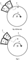
- FIG 4 is an overall view that illustrates a prior art solution without any elevated retention edges.
- the filter element 2 is part of a filter disc 25 as illustrated for example in figure 1 .
- the rotor shaft 3 rotates in a rotation direction R as illustrated in figure 2 .
- the water level (or level of liquid, not shown) is such that the filter element 2 is submerged during part of the rotary shaft 3 revolution, in the position as illustrated in figure 2 the filter element 2 is emerging through the surface of the liquid. Particles 35 fall both into the rotary shaft 3 where they are collected by a sludge collector and into the next filter element 2.
- next filter element 2 is actually another inside 4 of the same filter element 2, as in the embodiment shown in figures 2 and 3 .
- the filter elements 2 can have different shapes and forms within the scope of the solution as disclosed herein.
- FIG. 5 illustrates an embodiment of the present solution wherein elevated retention edges 30 as disclosed herein have been implemented to the prior art solution as illustrated in figure 4 .
- the elevated retention edges 30 are arranged in a center member of the filter element 2. As can be seen, the number of particles 35 passing through the passages 21 is significantly reduced. Instead, the particles 35 are restricted by the elevated retention edges 30 and slide down into the rotary shaft 3 wherein they are collected and separated from the filtration liquid.
- Figure 6 illustrates another embodiment of a filter element 2, wherein elevated retention edges 30a, 30b only are arranged for the passages 21a, 21b that are in liquid communication with an adjacent filter element being subsequent in a flow direction of liquid.
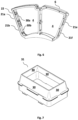
- Figure 7 illustrates one embodiment of an insert 31 adapted to fit in a passage.
- the insert 31 has elevated edges 30 arranged at an angle.
- Figure 8 illustrates another embodiment of an insert 31 adapted to fit in a passage 21, wherein the insert 31 comprises an aperture 33 for attachment means 18, such as a long bolt. It shall be noted that the appended figures only disclose examples of possible embodiments of the solution as disclosed herein.
- Figure 9 illustrates a module 36 that, when put together with another module 36, creates a filter element.
- the space delimited by two modules is covered by two filter cloth frames (not shown), one on each side of the space, thereby creating the filter element.
- the edge structure is arranged as a center member 22a.
- the filter elements may have different shape and form within the scope of the solution as disclosed herein.
- Figure 10 illustrates a filter element 2 wherein elevated retention edges 30a, 30b, 30c, and 30d are provided in passages 21a, 21b, 21c, and 21d, respectively, only for the passages that are in liquid communication with an adjacent filter element being subsequent in a flow direction of liquid.
- This filter element has one single inside 4 since the central structure 22a is essentially an opening, allowing free flow of water within the space defined by the edge structure 22 and the filter cloths (not shown) attached thereto.
- this design is similar to the one shown in the overall view of figure 1 .
Landscapes
- Chemical & Material Sciences (AREA)
- Chemical Kinetics & Catalysis (AREA)
- Filtration Of Liquid (AREA)
- Filtering Of Dispersed Particles In Gases (AREA)
- Food-Manufacturing Devices (AREA)
- Filtering Materials (AREA)
- Separation Using Semi-Permeable Membranes (AREA)
Claims (6)
- Filterelement (2) zur Verwendung in einer Filterscheibe (25), wobei eine Vielzahl von Filterelementen (2) auf einer Rotorwelle (3) in einer Weise angeordnet ist, die eine Flüssig-Verbindung zwischen der Innenseite (4) der Filterelemente (2) und einem Inneren (5) der Rotorwelle (3) ermöglicht, wobei jedes Filterelement (2) mindestens einen Durchgang (21) in einer Randstruktur (22) für eine Flüssig-Verbindung zwischen der Innenseite (4) eines benachbarten Filterelements (2) aufweist, wenn die Filterelemente (2) zu einer Filterscheibe (25) zusammengesetzt sind, dadurch gekennzeichnet, dass der Durchgang (21) einen erhöhten Rückhalterand (30) aufweist, der sich entlang mindestens eines Rands des Durchgangs (21) nach innen in Richtung der Innenseite (4) des Filterelements (2) erstreckt.
- Filterelement (2) nach Anspruch 1, wobei sich der erhöhte Rückhalterand (30) in die Innenseite (4) des Filterelements (2) in einer Drehrichtung (R) der Filterscheibe (25) erstreckt.
- Filterelement (2) nach einem der Ansprüche 1 bis 2, wobei der erhöhte Rückhalterand (30) nach innen zum Durchgang (21) hin geneigt ist.
- Filterelement (2) nach einem der Ansprüche 1 bis 3, wobei der erhöhte Rückhalterand (30) ein in den Durchgang (21) passender separater Einsatz (31) ist.
- Filterelement (2) nach einem der Ansprüche 1 bis 4, wobei der erhöhte Rückhalterand (3) Öffnungen zur Verringerung von Flüssigkeitsstörungen aufweist.
- Filterelement (2) nach einem der Ansprüche 1 bis 5, wobei sich der erhöhte Rückhalterand (30) entlang der Ränder mehrerer Durchgänge (21) erstreckt.
Applications Claiming Priority (2)
| Application Number | Priority Date | Filing Date | Title |
|---|---|---|---|
| SE1950945A SE543498C2 (en) | 2019-08-19 | 2019-08-19 | Filter element for filter disc comprising elevated restriction edges |
| PCT/SE2020/050795 WO2021034258A1 (en) | 2019-08-19 | 2020-08-17 | Filter element for filter disc comprising elevated restriction edges |
Publications (3)
| Publication Number | Publication Date |
|---|---|
| EP3965914A1 EP3965914A1 (de) | 2022-03-16 |
| EP3965914A4 EP3965914A4 (de) | 2022-04-27 |
| EP3965914B1 true EP3965914B1 (de) | 2023-04-12 |
Family
ID=74660347
Family Applications (1)
| Application Number | Title | Priority Date | Filing Date |
|---|---|---|---|
| EP20855763.7A Active EP3965914B1 (de) | 2019-08-19 | 2020-08-17 | Filterelement für filterscheibe mit erhöhten begrenzungskanten |
Country Status (6)
| Country | Link |
|---|---|
| US (1) | US20220161164A1 (de) |
| EP (1) | EP3965914B1 (de) |
| ES (1) | ES2942741T3 (de) |
| FI (1) | FI3965914T3 (de) |
| SE (1) | SE543498C2 (de) |
| WO (1) | WO2021034258A1 (de) |
Families Citing this family (1)
| Publication number | Priority date | Publication date | Assignee | Title |
|---|---|---|---|---|
| WO2025018930A1 (en) * | 2023-07-20 | 2025-01-23 | N P Innovation Ab | Disc panel unit, disc filter disc and disc filter apparatus |
Family Cites Families (9)
| Publication number | Priority date | Publication date | Assignee | Title |
|---|---|---|---|---|
| US3425149A (en) * | 1967-08-07 | 1969-02-04 | Sonoco Products Co | Identification insert for textile carrier |
| DE3722327A1 (de) * | 1987-07-07 | 1989-02-09 | Nova Pro Attachment Gmbh | Matrize fuer eine druckknopfpatrize |
| CN102527134B (zh) * | 2006-08-14 | 2014-12-10 | 伊沃夸水处理技术有限责任公司 | 高流量盘式过滤器 |
| KR100728307B1 (ko) * | 2006-09-28 | 2007-06-13 | 주식회사 유천엔바이로 | 융모형 여과막이 적용된 엘레먼트 및 이러한 엘레먼트가적용된 오폐수 여과용 디스크 필터장치 |
| US8118175B2 (en) * | 2007-07-18 | 2012-02-21 | Siemens Industry, Inc. | Venting device for a disc filter |
| SE533036C2 (sv) * | 2008-02-22 | 2010-06-15 | Nordic Water Prod Ab | Filterelement för skivfilter |
| KR101692162B1 (ko) * | 2015-08-10 | 2017-01-02 | 두산중공업 주식회사 | 고속 침전조 및 이를 포함하는 수처리 장치 |
| SE540721C2 (en) * | 2017-06-02 | 2018-10-23 | Nordic Water Prod Ab | Filter element for use in a filter disc |
| US11000791B2 (en) | 2019-03-06 | 2021-05-11 | Veolia Water Solutions & Technologies Support | Rotary disc filter having backwash guides |
-
2019
- 2019-08-19 SE SE1950945A patent/SE543498C2/en not_active IP Right Cessation
-
2020
- 2020-08-17 FI FIEP20855763.7T patent/FI3965914T3/fi active
- 2020-08-17 US US17/620,249 patent/US20220161164A1/en not_active Abandoned
- 2020-08-17 EP EP20855763.7A patent/EP3965914B1/de active Active
- 2020-08-17 WO PCT/SE2020/050795 patent/WO2021034258A1/en not_active Ceased
- 2020-08-17 ES ES20855763T patent/ES2942741T3/es active Active
Also Published As
| Publication number | Publication date |
|---|---|
| EP3965914A4 (de) | 2022-04-27 |
| FI3965914T3 (fi) | 2023-06-29 |
| WO2021034258A1 (en) | 2021-02-25 |
| ES2942741T3 (es) | 2023-06-06 |
| US20220161164A1 (en) | 2022-05-26 |
| EP3965914A1 (de) | 2022-03-16 |
| SE1950945A1 (en) | 2021-02-20 |
| SE543498C2 (en) | 2021-03-09 |
Similar Documents
| Publication | Publication Date | Title |
|---|---|---|
| US9339745B2 (en) | Trash tolerant filter support for a disc filter | |
| EP2164947B1 (de) | Entlüftungsvorrichtung für einen scheibenfilter | |
| EP2051791B1 (de) | Scheibenfilter mit hohem durchfluss | |
| EP2244802B1 (de) | Filterelement für einen scheibenfilter | |
| EP3630330B1 (de) | Filterscheibe | |
| AU2016284836B2 (en) | Filter panel with structures support grid and drum filter with said filter panel | |
| EP3965914B1 (de) | Filterelement für filterscheibe mit erhöhten begrenzungskanten | |
| EP2750781B1 (de) | Filtersegmente mit leichtem rahmen | |
| HK1197899A (zh) | 用於液体处理尤其是用於盘式废水过滤器设备的过滤器板 | |
| HK1197899B (en) | Filter panel for the treatment of liquids, especially for disc wastewater filter equipment |
Legal Events
| Date | Code | Title | Description |
|---|---|---|---|
| STAA | Information on the status of an ep patent application or granted ep patent |
Free format text: STATUS: THE INTERNATIONAL PUBLICATION HAS BEEN MADE |
|
| PUAI | Public reference made under article 153(3) epc to a published international application that has entered the european phase |
Free format text: ORIGINAL CODE: 0009012 |
|
| STAA | Information on the status of an ep patent application or granted ep patent |
Free format text: STATUS: REQUEST FOR EXAMINATION WAS MADE |
|
| 17P | Request for examination filed |
Effective date: 20211207 |
|
| AK | Designated contracting states |
Kind code of ref document: A1 Designated state(s): AL AT BE BG CH CY CZ DE DK EE ES FI FR GB GR HR HU IE IS IT LI LT LU LV MC MK MT NL NO PL PT RO RS SE SI SK SM TR |
|
| STAA | Information on the status of an ep patent application or granted ep patent |
Free format text: STATUS: EXAMINATION IS IN PROGRESS |
|
| A4 | Supplementary search report drawn up and despatched |
Effective date: 20220330 |
|
| RIC1 | Information provided on ipc code assigned before grant |
Ipc: B01D 33/21 20060101ALI20220324BHEP Ipc: B01D 33/23 20060101AFI20220324BHEP |
|
| 17Q | First examination report despatched |
Effective date: 20220411 |
|
| GRAP | Despatch of communication of intention to grant a patent |
Free format text: ORIGINAL CODE: EPIDOSNIGR1 |
|
| STAA | Information on the status of an ep patent application or granted ep patent |
Free format text: STATUS: GRANT OF PATENT IS INTENDED |
|
| DAV | Request for validation of the european patent (deleted) | ||
| DAX | Request for extension of the european patent (deleted) | ||
| INTG | Intention to grant announced |
Effective date: 20221116 |
|
| TPAC | Observations filed by third parties |
Free format text: ORIGINAL CODE: EPIDOSNTIPA |
|
| RAP1 | Party data changed (applicant data changed or rights of an application transferred) |
Owner name: SULZER MANAGEMENT AG |
|
| GRAS | Grant fee paid |
Free format text: ORIGINAL CODE: EPIDOSNIGR3 |
|
| GRAA | (expected) grant |
Free format text: ORIGINAL CODE: 0009210 |
|
| STAA | Information on the status of an ep patent application or granted ep patent |
Free format text: STATUS: THE PATENT HAS BEEN GRANTED |
|
| AK | Designated contracting states |
Kind code of ref document: B1 Designated state(s): AL AT BE BG CH CY CZ DE DK EE ES FI FR GB GR HR HU IE IS IT LI LT LU LV MC MK MT NL NO PL PT RO RS SE SI SK SM TR |
|
| REG | Reference to a national code |
Ref country code: GB Ref legal event code: FG4D |
|
| REG | Reference to a national code |
Ref country code: CH Ref legal event code: EP |
|
| REG | Reference to a national code |
Ref country code: DE Ref legal event code: R096 Ref document number: 602020009757 Country of ref document: DE |
|
| REG | Reference to a national code |
Ref country code: IE Ref legal event code: FG4D |
|
| REG | Reference to a national code |
Ref country code: AT Ref legal event code: REF Ref document number: 1559469 Country of ref document: AT Kind code of ref document: T Effective date: 20230515 |
|
| REG | Reference to a national code |
Ref country code: ES Ref legal event code: FG2A Ref document number: 2942741 Country of ref document: ES Kind code of ref document: T3 Effective date: 20230606 |
|
| P01 | Opt-out of the competence of the unified patent court (upc) registered |
Effective date: 20230412 |
|
| REG | Reference to a national code |
Ref country code: FI Ref legal event code: FGE |
|
| REG | Reference to a national code |
Ref country code: SE Ref legal event code: TRGR |
|
| REG | Reference to a national code |
Ref country code: LT Ref legal event code: MG9D |
|
| REG | Reference to a national code |
Ref country code: NL Ref legal event code: MP Effective date: 20230412 |
|
| REG | Reference to a national code |
Ref country code: AT Ref legal event code: MK05 Ref document number: 1559469 Country of ref document: AT Kind code of ref document: T Effective date: 20230412 |
|
| PG25 | Lapsed in a contracting state [announced via postgrant information from national office to epo] |
Ref country code: NL Free format text: LAPSE BECAUSE OF FAILURE TO SUBMIT A TRANSLATION OF THE DESCRIPTION OR TO PAY THE FEE WITHIN THE PRESCRIBED TIME-LIMIT Effective date: 20230412 |
|
| PG25 | Lapsed in a contracting state [announced via postgrant information from national office to epo] |
Ref country code: PT Free format text: LAPSE BECAUSE OF FAILURE TO SUBMIT A TRANSLATION OF THE DESCRIPTION OR TO PAY THE FEE WITHIN THE PRESCRIBED TIME-LIMIT Effective date: 20230814 Ref country code: NO Free format text: LAPSE BECAUSE OF FAILURE TO SUBMIT A TRANSLATION OF THE DESCRIPTION OR TO PAY THE FEE WITHIN THE PRESCRIBED TIME-LIMIT Effective date: 20230712 Ref country code: AT Free format text: LAPSE BECAUSE OF FAILURE TO SUBMIT A TRANSLATION OF THE DESCRIPTION OR TO PAY THE FEE WITHIN THE PRESCRIBED TIME-LIMIT Effective date: 20230412 |
|
| PG25 | Lapsed in a contracting state [announced via postgrant information from national office to epo] |
Ref country code: RS Free format text: LAPSE BECAUSE OF FAILURE TO SUBMIT A TRANSLATION OF THE DESCRIPTION OR TO PAY THE FEE WITHIN THE PRESCRIBED TIME-LIMIT Effective date: 20230412 Ref country code: PL Free format text: LAPSE BECAUSE OF FAILURE TO SUBMIT A TRANSLATION OF THE DESCRIPTION OR TO PAY THE FEE WITHIN THE PRESCRIBED TIME-LIMIT Effective date: 20230412 Ref country code: LV Free format text: LAPSE BECAUSE OF FAILURE TO SUBMIT A TRANSLATION OF THE DESCRIPTION OR TO PAY THE FEE WITHIN THE PRESCRIBED TIME-LIMIT Effective date: 20230412 Ref country code: LT Free format text: LAPSE BECAUSE OF FAILURE TO SUBMIT A TRANSLATION OF THE DESCRIPTION OR TO PAY THE FEE WITHIN THE PRESCRIBED TIME-LIMIT Effective date: 20230412 Ref country code: IS Free format text: LAPSE BECAUSE OF FAILURE TO SUBMIT A TRANSLATION OF THE DESCRIPTION OR TO PAY THE FEE WITHIN THE PRESCRIBED TIME-LIMIT Effective date: 20230812 Ref country code: HR Free format text: LAPSE BECAUSE OF FAILURE TO SUBMIT A TRANSLATION OF THE DESCRIPTION OR TO PAY THE FEE WITHIN THE PRESCRIBED TIME-LIMIT Effective date: 20230412 Ref country code: GR Free format text: LAPSE BECAUSE OF FAILURE TO SUBMIT A TRANSLATION OF THE DESCRIPTION OR TO PAY THE FEE WITHIN THE PRESCRIBED TIME-LIMIT Effective date: 20230713 Ref country code: AL Free format text: LAPSE BECAUSE OF FAILURE TO SUBMIT A TRANSLATION OF THE DESCRIPTION OR TO PAY THE FEE WITHIN THE PRESCRIBED TIME-LIMIT Effective date: 20230412 |
|
| REG | Reference to a national code |
Ref country code: DE Ref legal event code: R097 Ref document number: 602020009757 Country of ref document: DE |
|
| PG25 | Lapsed in a contracting state [announced via postgrant information from national office to epo] |
Ref country code: SK Free format text: LAPSE BECAUSE OF FAILURE TO SUBMIT A TRANSLATION OF THE DESCRIPTION OR TO PAY THE FEE WITHIN THE PRESCRIBED TIME-LIMIT Effective date: 20230412 |
|
| PG25 | Lapsed in a contracting state [announced via postgrant information from national office to epo] |
Ref country code: SM Free format text: LAPSE BECAUSE OF FAILURE TO SUBMIT A TRANSLATION OF THE DESCRIPTION OR TO PAY THE FEE WITHIN THE PRESCRIBED TIME-LIMIT Effective date: 20230412 Ref country code: SK Free format text: LAPSE BECAUSE OF FAILURE TO SUBMIT A TRANSLATION OF THE DESCRIPTION OR TO PAY THE FEE WITHIN THE PRESCRIBED TIME-LIMIT Effective date: 20230412 Ref country code: RO Free format text: LAPSE BECAUSE OF FAILURE TO SUBMIT A TRANSLATION OF THE DESCRIPTION OR TO PAY THE FEE WITHIN THE PRESCRIBED TIME-LIMIT Effective date: 20230412 Ref country code: EE Free format text: LAPSE BECAUSE OF FAILURE TO SUBMIT A TRANSLATION OF THE DESCRIPTION OR TO PAY THE FEE WITHIN THE PRESCRIBED TIME-LIMIT Effective date: 20230412 Ref country code: DK Free format text: LAPSE BECAUSE OF FAILURE TO SUBMIT A TRANSLATION OF THE DESCRIPTION OR TO PAY THE FEE WITHIN THE PRESCRIBED TIME-LIMIT Effective date: 20230412 Ref country code: CZ Free format text: LAPSE BECAUSE OF FAILURE TO SUBMIT A TRANSLATION OF THE DESCRIPTION OR TO PAY THE FEE WITHIN THE PRESCRIBED TIME-LIMIT Effective date: 20230412 |
|
| PLBE | No opposition filed within time limit |
Free format text: ORIGINAL CODE: 0009261 |
|
| STAA | Information on the status of an ep patent application or granted ep patent |
Free format text: STATUS: NO OPPOSITION FILED WITHIN TIME LIMIT |
|
| PG25 | Lapsed in a contracting state [announced via postgrant information from national office to epo] |
Ref country code: MC Free format text: LAPSE BECAUSE OF FAILURE TO SUBMIT A TRANSLATION OF THE DESCRIPTION OR TO PAY THE FEE WITHIN THE PRESCRIBED TIME-LIMIT Effective date: 20230412 |
|
| 26N | No opposition filed |
Effective date: 20240115 |
|
| REG | Reference to a national code |
Ref country code: CH Ref legal event code: PL |
|
| PG25 | Lapsed in a contracting state [announced via postgrant information from national office to epo] |
Ref country code: MC Free format text: LAPSE BECAUSE OF FAILURE TO SUBMIT A TRANSLATION OF THE DESCRIPTION OR TO PAY THE FEE WITHIN THE PRESCRIBED TIME-LIMIT Effective date: 20230412 |
|
| PG25 | Lapsed in a contracting state [announced via postgrant information from national office to epo] |
Ref country code: LU Free format text: LAPSE BECAUSE OF NON-PAYMENT OF DUE FEES Effective date: 20230817 |
|
| PG25 | Lapsed in a contracting state [announced via postgrant information from national office to epo] |
Ref country code: LU Free format text: LAPSE BECAUSE OF NON-PAYMENT OF DUE FEES Effective date: 20230817 Ref country code: CH Free format text: LAPSE BECAUSE OF NON-PAYMENT OF DUE FEES Effective date: 20230831 |
|
| PG25 | Lapsed in a contracting state [announced via postgrant information from national office to epo] |
Ref country code: SI Free format text: LAPSE BECAUSE OF FAILURE TO SUBMIT A TRANSLATION OF THE DESCRIPTION OR TO PAY THE FEE WITHIN THE PRESCRIBED TIME-LIMIT Effective date: 20230412 |
|
| REG | Reference to a national code |
Ref country code: BE Ref legal event code: MM Effective date: 20230831 |
|
| REG | Reference to a national code |
Ref country code: IE Ref legal event code: MM4A |
|
| PG25 | Lapsed in a contracting state [announced via postgrant information from national office to epo] |
Ref country code: SI Free format text: LAPSE BECAUSE OF FAILURE TO SUBMIT A TRANSLATION OF THE DESCRIPTION OR TO PAY THE FEE WITHIN THE PRESCRIBED TIME-LIMIT Effective date: 20230412 Ref country code: IT Free format text: LAPSE BECAUSE OF FAILURE TO SUBMIT A TRANSLATION OF THE DESCRIPTION OR TO PAY THE FEE WITHIN THE PRESCRIBED TIME-LIMIT Effective date: 20230412 |
|
| PG25 | Lapsed in a contracting state [announced via postgrant information from national office to epo] |
Ref country code: IE Free format text: LAPSE BECAUSE OF NON-PAYMENT OF DUE FEES Effective date: 20230817 |
|
| PG25 | Lapsed in a contracting state [announced via postgrant information from national office to epo] |
Ref country code: IE Free format text: LAPSE BECAUSE OF NON-PAYMENT OF DUE FEES Effective date: 20230817 |
|
| PG25 | Lapsed in a contracting state [announced via postgrant information from national office to epo] |
Ref country code: BE Free format text: LAPSE BECAUSE OF NON-PAYMENT OF DUE FEES Effective date: 20230831 |
|
| PG25 | Lapsed in a contracting state [announced via postgrant information from national office to epo] |
Ref country code: BG Free format text: LAPSE BECAUSE OF FAILURE TO SUBMIT A TRANSLATION OF THE DESCRIPTION OR TO PAY THE FEE WITHIN THE PRESCRIBED TIME-LIMIT Effective date: 20230412 |
|
| PG25 | Lapsed in a contracting state [announced via postgrant information from national office to epo] |
Ref country code: BG Free format text: LAPSE BECAUSE OF FAILURE TO SUBMIT A TRANSLATION OF THE DESCRIPTION OR TO PAY THE FEE WITHIN THE PRESCRIBED TIME-LIMIT Effective date: 20230412 |
|
| PG25 | Lapsed in a contracting state [announced via postgrant information from national office to epo] |
Ref country code: CY Free format text: LAPSE BECAUSE OF FAILURE TO SUBMIT A TRANSLATION OF THE DESCRIPTION OR TO PAY THE FEE WITHIN THE PRESCRIBED TIME-LIMIT; INVALID AB INITIO Effective date: 20200817 |
|
| PG25 | Lapsed in a contracting state [announced via postgrant information from national office to epo] |
Ref country code: HU Free format text: LAPSE BECAUSE OF FAILURE TO SUBMIT A TRANSLATION OF THE DESCRIPTION OR TO PAY THE FEE WITHIN THE PRESCRIBED TIME-LIMIT; INVALID AB INITIO Effective date: 20200817 |
|
| PGFP | Annual fee paid to national office [announced via postgrant information from national office to epo] |
Ref country code: FI Payment date: 20250822 Year of fee payment: 6 Ref country code: ES Payment date: 20250926 Year of fee payment: 6 |
|
| PGFP | Annual fee paid to national office [announced via postgrant information from national office to epo] |
Ref country code: DE Payment date: 20250820 Year of fee payment: 6 |
|
| PGFP | Annual fee paid to national office [announced via postgrant information from national office to epo] |
Ref country code: GB Payment date: 20250820 Year of fee payment: 6 |
|
| PGFP | Annual fee paid to national office [announced via postgrant information from national office to epo] |
Ref country code: FR Payment date: 20250828 Year of fee payment: 6 |
|
| PGFP | Annual fee paid to national office [announced via postgrant information from national office to epo] |
Ref country code: SE Payment date: 20250820 Year of fee payment: 6 |
|
| PG25 | Lapsed in a contracting state [announced via postgrant information from national office to epo] |
Ref country code: TR Free format text: LAPSE BECAUSE OF FAILURE TO SUBMIT A TRANSLATION OF THE DESCRIPTION OR TO PAY THE FEE WITHIN THE PRESCRIBED TIME-LIMIT Effective date: 20230412 |