EP3969766B1 - Gewindebolzenpaar, pfostenverankerungssystem und verfahren zum befestigen eines pfostens an einem pfostenanker - Google Patents
Gewindebolzenpaar, pfostenverankerungssystem und verfahren zum befestigen eines pfostens an einem pfostenanker Download PDFInfo
- Publication number
- EP3969766B1 EP3969766B1 EP20804434.7A EP20804434A EP3969766B1 EP 3969766 B1 EP3969766 B1 EP 3969766B1 EP 20804434 A EP20804434 A EP 20804434A EP 3969766 B1 EP3969766 B1 EP 3969766B1
- Authority
- EP
- European Patent Office
- Prior art keywords
- post
- threaded
- threaded fastener
- fastener
- support
- Prior art date
- Legal status (The legal status is an assumption and is not a legal conclusion. Google has not performed a legal analysis and makes no representation as to the accuracy of the status listed.)
- Active
Links
Images


Classifications
-
- F—MECHANICAL ENGINEERING; LIGHTING; HEATING; WEAPONS; BLASTING
- F16—ENGINEERING ELEMENTS AND UNITS; GENERAL MEASURES FOR PRODUCING AND MAINTAINING EFFECTIVE FUNCTIONING OF MACHINES OR INSTALLATIONS; THERMAL INSULATION IN GENERAL
- F16B—DEVICES FOR FASTENING OR SECURING CONSTRUCTIONAL ELEMENTS OR MACHINE PARTS TOGETHER, e.g. NAILS, BOLTS, CIRCLIPS, CLAMPS, CLIPS OR WEDGES; JOINTS OR JOINTING
- F16B37/00—Nuts or like thread-engaging members
- F16B37/08—Quickly-detachable or mountable nuts, e.g. consisting of two or more parts; Nuts movable along the bolt after tilting the nut
- F16B37/0807—Nuts engaged from the end of the bolt, e.g. axially slidable nuts
- F16B37/0864—Nuts engaged from the end of the bolt, e.g. axially slidable nuts with the threaded portions of the nut engaging the thread of the bolt by pressing or rotating an external retaining member such as a cap, a nut, a ring or a sleeve
-
- E—FIXED CONSTRUCTIONS
- E04—BUILDING
- E04H—BUILDINGS OR LIKE STRUCTURES FOR PARTICULAR PURPOSES; SWIMMING OR SPLASH BATHS OR POOLS; MASTS; FENCING; TENTS OR CANOPIES, IN GENERAL
- E04H12/00—Towers; Masts or poles; Chimney stacks; Water-towers; Methods of erecting such structures
- E04H12/22—Sockets or holders for poles or posts
- E04H12/2253—Mounting poles or posts to the holder
- E04H12/2276—Clamping poles or posts on a stub
-
- F—MECHANICAL ENGINEERING; LIGHTING; HEATING; WEAPONS; BLASTING
- F16—ENGINEERING ELEMENTS AND UNITS; GENERAL MEASURES FOR PRODUCING AND MAINTAINING EFFECTIVE FUNCTIONING OF MACHINES OR INSTALLATIONS; THERMAL INSULATION IN GENERAL
- F16B—DEVICES FOR FASTENING OR SECURING CONSTRUCTIONAL ELEMENTS OR MACHINE PARTS TOGETHER, e.g. NAILS, BOLTS, CIRCLIPS, CLAMPS, CLIPS OR WEDGES; JOINTS OR JOINTING
- F16B37/00—Nuts or like thread-engaging members
- F16B37/04—Devices for fastening nuts to surfaces, e.g. sheets, plates
- F16B37/045—Devices for fastening nuts to surfaces, e.g. sheets, plates specially adapted for fastening in channels, e.g. sliding bolts, channel nuts
- F16B37/047—Barrel nuts
-
- F—MECHANICAL ENGINEERING; LIGHTING; HEATING; WEAPONS; BLASTING
- F16—ENGINEERING ELEMENTS AND UNITS; GENERAL MEASURES FOR PRODUCING AND MAINTAINING EFFECTIVE FUNCTIONING OF MACHINES OR INSTALLATIONS; THERMAL INSULATION IN GENERAL
- F16B—DEVICES FOR FASTENING OR SECURING CONSTRUCTIONAL ELEMENTS OR MACHINE PARTS TOGETHER, e.g. NAILS, BOLTS, CIRCLIPS, CLAMPS, CLIPS OR WEDGES; JOINTS OR JOINTING
- F16B37/00—Nuts or like thread-engaging members
- F16B37/14—Cap nuts; Nut caps or bolt caps
- F16B37/145—Sleeve nuts, e.g. combined with bolts
-
- F—MECHANICAL ENGINEERING; LIGHTING; HEATING; WEAPONS; BLASTING
- F16—ENGINEERING ELEMENTS AND UNITS; GENERAL MEASURES FOR PRODUCING AND MAINTAINING EFFECTIVE FUNCTIONING OF MACHINES OR INSTALLATIONS; THERMAL INSULATION IN GENERAL
- F16B—DEVICES FOR FASTENING OR SECURING CONSTRUCTIONAL ELEMENTS OR MACHINE PARTS TOGETHER, e.g. NAILS, BOLTS, CIRCLIPS, CLAMPS, CLIPS OR WEDGES; JOINTS OR JOINTING
- F16B5/00—Joining sheets or plates, e.g. panels, to one another or to strips or bars parallel to them
- F16B5/02—Joining sheets or plates, e.g. panels, to one another or to strips or bars parallel to them by means of fastening members using screw-thread
-
- F—MECHANICAL ENGINEERING; LIGHTING; HEATING; WEAPONS; BLASTING
- F16—ENGINEERING ELEMENTS AND UNITS; GENERAL MEASURES FOR PRODUCING AND MAINTAINING EFFECTIVE FUNCTIONING OF MACHINES OR INSTALLATIONS; THERMAL INSULATION IN GENERAL
- F16B—DEVICES FOR FASTENING OR SECURING CONSTRUCTIONAL ELEMENTS OR MACHINE PARTS TOGETHER, e.g. NAILS, BOLTS, CIRCLIPS, CLAMPS, CLIPS OR WEDGES; JOINTS OR JOINTING
- F16B7/00—Connections of rods or tubes, e.g. of non-circular section, mutually, including resilient connections
- F16B7/18—Connections of rods or tubes, e.g. of non-circular section, mutually, including resilient connections using screw-thread elements
- F16B7/182—Connections of rods or tubes, e.g. of non-circular section, mutually, including resilient connections using screw-thread elements for coaxial connections of two rods or tubes
-
- E—FIXED CONSTRUCTIONS
- E04—BUILDING
- E04C—STRUCTURAL ELEMENTS; BUILDING MATERIALS
- E04C3/00—Structural elongated elements designed for load-supporting
- E04C3/02—Joists; Girders, trusses, or trusslike structures, e.g. prefabricated; Lintels; Transoms; Braces
- E04C3/12—Joists; Girders, trusses, or trusslike structures, e.g. prefabricated; Lintels; Transoms; Braces of wood, e.g. with reinforcements, with tensioning members
- E04C3/16—Joists; Girders, trusses, or trusslike structures, e.g. prefabricated; Lintels; Transoms; Braces of wood, e.g. with reinforcements, with tensioning members with apertured web, e.g. trusses
-
- E—FIXED CONSTRUCTIONS
- E04—BUILDING
- E04H—BUILDINGS OR LIKE STRUCTURES FOR PARTICULAR PURPOSES; SWIMMING OR SPLASH BATHS OR POOLS; MASTS; FENCING; TENTS OR CANOPIES, IN GENERAL
- E04H12/00—Towers; Masts or poles; Chimney stacks; Water-towers; Methods of erecting such structures
- E04H12/22—Sockets or holders for poles or posts
- E04H12/2253—Mounting poles or posts to the holder
- E04H12/2269—Mounting poles or posts to the holder in a socket
-
- F—MECHANICAL ENGINEERING; LIGHTING; HEATING; WEAPONS; BLASTING
- F16—ENGINEERING ELEMENTS AND UNITS; GENERAL MEASURES FOR PRODUCING AND MAINTAINING EFFECTIVE FUNCTIONING OF MACHINES OR INSTALLATIONS; THERMAL INSULATION IN GENERAL
- F16B—DEVICES FOR FASTENING OR SECURING CONSTRUCTIONAL ELEMENTS OR MACHINE PARTS TOGETHER, e.g. NAILS, BOLTS, CIRCLIPS, CLAMPS, CLIPS OR WEDGES; JOINTS OR JOINTING
- F16B37/00—Nuts or like thread-engaging members
- F16B2037/007—Nuts or like thread-engaging members with a blind hole
Definitions
- connections including for example, timber to timber connections, particularly for roof truss connections, joist connections, staircases, handrails, exposed beams, architectural timber connections, exposed rafter connections, and LVL beam connector bolts.
- a further application of such a connection is with a post support or anchor for a vertical post.
- Post supports are a convenient way of supporting and securing a vertical post to a ground surface such as concrete.
- some previous post anchors have been visually unappealing and also typically require traditional bolts extending transversely through an end of the post for securing the post to the anchor and this results, on one side of the anchor, in a nut and exposed thread being visible and exposed for unintentional contact.
- Such an arrangement is visually undesirable and unintentional contact with an exposed end of a threaded bolt has the potential to cause injury.
- US 2009/288356 A1 discloses an anchor bolt and a threaded sleeve for fixing a framing plate to a support structure, wherein the anchor bolt comprising a threaded shaft bearing threads, while the threaded sleeve member comprising internal threads compatible with the threads of the anchor bolts.
- US 4 033 243 A provides a fastener assembly for attaching a composite panel section or the like to a frame section.
- the fastener assembly comprises a bolt member having a tamperproof enlarged head portion, and a nut member engageable with the bolt member.
- KR 2009 0007770 U discloses a fixed structure for a handrail, wherein the fixed structure comprising an anchor bolt embedded in a floor and protruding upwards out of the floor, a washer and a nut screwed onto the anchor bolt.
- a threaded fastener pair including:
- the length of the first threaded fastener is at least 45mm.
- a shank of the first threaded fastener is at least 5mm long and has a diameter of at least 10mm.
- each fastener is formed with a domed head having a socket drive.
- the blade portion is centrally disposed on the support which is configured to be received in a slit formed in an end of the post.
- the slit extends along a central longitudinal axis of the post.
- the system may have two, three or four threaded fastener pairs.
- the post support may have a concealing cap to cover a bolt down portion at a lower portion of the post support.
- a method of securing a post to a post support including the steps of:
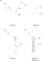
- a threaded fastener pair 10 according to a preferred embodiment of the invention is illustrated in Figure 1 .
- the fasteners are of equal length and length A2 equals length B2. Also, length A1 equals length B1, with B1 being the length of which fastener 14 extends past the midpoint or centreline x between the heads of each fastener.
- the first fastener 12 is formed with a shank 16 having an outer diameter approximately equal to an outer diameter of the second fastener 14.
- the shank 16 of the first threaded fastener 12 is at least 5mm long and has a diameter of at least 10mm.
- the second threaded fastener 14 has a length equal to or greater than that of the first threaded fastener 12 and the length of the first threaded fastener 12 is at least 45mm.
- the first threaded fastener 12 is available in lengths of 45mm, 50mm, 70mm, 110mm and 190mm, though it will be appreciated that longer lengths may also be possible.
- the female threaded portion 15 is quite long compared to prior art fasteners of this type. To allow such a deep thread to be formed, at a base of the female threaded portion is an unthreaded bore 18.
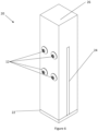
- Figures 6 , 7a and 7b illustrate the threaded fastener pair 10 in use with a post support system 20 of a first embodiment, which includes a post support 22 having an upwardly extending blade 24, and a generally vertical post 26.
- a post support 22 having an upwardly extending blade 24, and a generally vertical post 26.
- four threaded fastener pairs are used and extend through apertures 17 formed in the blade 24.
- the post support 22 is provided with apertures 23 to allow securement of the post 22 to a ground surface.
- the size of the first and second fasteners is chosen to provide a sufficient overlap, which is preferably 30mm, at the centre of the connection, i.e. the midpoint between the heads of the first and second fasteners 12, 14, so that not only the blade 24 is supported on the fastener pair 10, but the post immediately beside the blade 24 is well supported on both sides of the blade 24 and also by the shank 16 near the head of the first fastener 12.
- This provides a secure connection between the post 26 and the post support 22, with equivalent strength to a conventional bolted connection, but without suffering the above mentioned drawbacks of using conventional threaded fasteners.
- a threaded fastener pair of a male/female threaded fasteners 12, 14 allows any excess thread to be accommodated within the connection of the fasteners so that the only parts visible from outside of the system are two bolt heads, which are preferably domed heads. This provides a nice clean finish, and removes any exposed thread/nuts that can look untidy and may unintentionally cause injury. Such an arrangement also means that a limited number of sizes can be provided for multiple applications.
- the fastener heads may take other forms such as a standard hexagon head, rounded screw head, button or countersunk hexagon socket for example.
- FIG. 8 Another example of post support 122 for use with the threaded fastener pair and post support system is illustrated in Figure 8 .
- two apertures 117 are formed in the blade 124 through which a threaded fastener pair can extend to secure the post to the support 122.
- the number of threaded fastener pairs used can be varied.
- the post support 122 includes a base 128 to be received against a surface to which the post is to be secured, which is typically a concrete surface, and an aperture 130 through which a fastener can extend to secure the post support 122 to the surface.
- a stand 132 is provided to space the end of the post from the ground surface and may be any desired length.
- a plate 134 is secured to the stand 132 and provided for abutment with an end of the post.
- Figure 9a illustrates another post support 222 for use with the threaded fastener pair and a further embodiment of the post support system.
- stand 132 and plate 134 are omitted, with blade portion 224 being provided with a mounting flange 236 for securement to the surface.
- Post support 222 may be formed of a single piece of material, or from two or more pieces of material.
- a concealing cap 238 is provided to cover the flange 236 and end of the blade portion 224 to provide a clean finish. In use, after flange 236 is secured to a surface, cap 238 is passed over the bladed portion 224 before the post is secured to the post support 222.
- a slit is first cut in an end of a post to be secured.
- the slit is formed to correspond to a blade portion 24, 124, 224 of the post support.
- Transverse holes are formed in the same end of the post 12 and positioned to align with apertures 17, 117 formed in the support 22, 122, 222, which is secured to a ground surface, which may be a concrete surface for example, using commonly available concrete fasteners.
- FIGS 10 , 11a and 11b illustrate a further post support system 320.
- This system 329 uses a post support 322 having a "U" or saddle shape, having two upstanding blade portions 124, which are configured to be received on opposite external sides of the post 326.
- post support 322 has a base 328 to be received against a surface to which the post is to be secured, which is typically a concrete surface, and two apertures 330 through which a fastener can extend to secure the post support 322 to the surface.
- a stand 332 is provided to space the end of the post from the ground surface and may be any desired length.
- a support portion 334 is secured to the stand 332 and provided for abutment with an end of the post. In the illustrated embodiment, the support portion 334 and the two blade portions 324 are integrally formed.
- the post support 322 is supported on both sides by close engagement with the male/female threaded fasteners 12, 14.
- the post support 322 sits on the female fastener 14 and on the other side the post support 322 sits on the shank of the male fastener 12.
- Using a threaded fastener pair of a male/female threaded fasteners 12, 14 allows any excess thread to be accommodated within the connection of the fasteners so that the only parts visible from outside of the system are two bolt heads, which are preferably domed heads. This provides a nice clean finish, and removes any exposed thread/nuts that can look untidy and may unintentionally cause injury.
- each fastener is solid where it passes through the blade portion 324 and into the post. As such the post sits on a solid section within the fasteners so as to mimic the load support of a conventional bolt. If the female fastener was hollow in this area, it could be vulnerable to shear under high loading.
- post anchors can come in many different sizes and configurations for use in different applications and with differently sized posts.
- different post anchors may have differently sized plates and stands, number and sizes of apertures and lengths of blade.
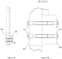
- Figures 12 , 13a and 13b illustrate the use of the fastener pair 10 in a timber to timber connection 450.
- the length of the first and second fasteners is chosen to provide a sufficient overlap, which is preferably 30mm, at the centre of the connection, i.e. the midpoint between the heads of the first and second fasteners 12, 14, so that both the bottom chord 452 and the web 454 are located/aligned with each other and well supported on the bore of the apertures formed therein.
- the female threaded fastener 14 extends through the bottom chord 452 and partially into the web 454, which is supported on one side by the female threaded fastener and at the other side, the shank 16 of the first threaded fastener 12.
- a threaded fastener pair is provided for each aperture formed in the material to be connected, which may be a post with a post anchor or a bottom chord and webs of a truss.
- the fasteners of the pair are inserted into the apertures from opposite sides of the joint. Once the fasteners are in engagement with each other, they can be tightened so that a head of each fastener clamps against an external surface of the materials to secure them together. The result is a secure, well supported and visually clean joint, without an exposed end of a threaded fastener being visible.
Landscapes
- Engineering & Computer Science (AREA)
- General Engineering & Computer Science (AREA)
- Mechanical Engineering (AREA)
- Architecture (AREA)
- Civil Engineering (AREA)
- Structural Engineering (AREA)
- Joining Of Building Structures In Genera (AREA)
- Piles And Underground Anchors (AREA)
Claims (14)
- Ein Paar von Gewindebefestigungen (10), beinhaltend:eine erste Gewindebefestigung (12) mit einem Außengewindebereich (13); undeine zweite Gewindebefestigung (14) mit einem Innengewindebereich (15), wobei der Innengewindebereich (15) so konfiguriert ist, dass er den Außengewindebereich (13) aufnimmt,dadurch gekennzeichnet, dass die erste Gewindebefestigung (12) mit einem Schaft (16) ausgebildet ist, der einen Außendurchmesser aufweist, der ungefähr gleich einem Außendurchmesser des zweiten Gewindebereichs ist, und dass die zweite Gewindebefestigung (14) eine Länge aufweist, die gleich oder größer als die der ersten Gewindebefestigung (12) ist, so dass der Außendurchmesser des zweiten Gewindebereichs eine Last an einem Mittelpunkt zwischen äußeren Enden der Gewindebefestigungen (12, 14) trägt.
- Ein Paar von Gewindebefestigungen (10) gemäß Anspruch 1, wobei sich an einer Basis des Innengewindebereichs (15) eine gewindelose zylindrische Bohrung befindet.
- Ein Paar von Gewindebefestigungen (10) gemäß Anspruch 1 oder Anspruch 2, wobei die Länge der ersten Gewindebefestigung (12) mindestens 45 mm beträgt.
- Ein Paar von Gewindebefestigungen (10) gemäß einem der vorhergehenden Ansprüche, wobei ein Schaft (16) der ersten Gewindebefestigung (12) mindestens 5 mm lang ist und einen Durchmesser von mindestens 10 mm aufweist.
- Ein Paar von Gewindebefestigungen (10) gemäß einem der vorhergehenden Ansprüche, wobei jede Gewindebefestigung (12, 14) mit einem gewölbten Kopf aufweisend einen Muffenantrieb ausgebildet ist.
- Pfostenankersystem, umfassend:eine Pfostenstütze (22, 122, 222), die an einer Bodenfläche befestigbar ist und mindestens einen Blattbereich (24, 124, 224) aufweist, der sich davon nach oben erstreckt, um mit einem im Allgemeinen vertikalen Pfosten in Eingriff zu kommen, wobei der Blattbereich (24, 124, 224) mindestens eine Öffnung (17, 117) aufweist, durch die sich eine Gewindebefestigung (12, 14) erstrecken kann, um den Pfosten an der Stütze (22, 122, 222) zu befestigen; undmindestens ein Paar von Gewindebefestigungen (10), beinhaltend:eine erste Gewindebefestigung (12) mit einem Außengewindebereich (13); undeine zweite Gewindebefestigung (14) mit einem Innengewindebereich (15), wobei der Innengewindebereich so konfiguriert ist, dass er den Außengewindebereich (13) aufnimmt,wobei die erste Gewindebefestigung (12) mit einem Schaft (16) ausgebildet ist, der einen Außendurchmesser aufweist, der ungefähr gleich einem Außendurchmesser des zweiten Gewindebereichs ist, undwobei die zweite Gewindebefestigung (14) eine Länge aufweist, die gleich oder größer ist als die der ersten Gewindebefestigung (12), so dass bei der Verwendung ein Ende der zweiten Gewindebefestigung (14) die erste Gewindebefestigung (12) an einer zentralen Stelle überlappt, um den Blattbereich (24, 124, 224) der Pfostenstütze (22, 122, 222) in Eingriff mit einer Außenfläche des zweiten Gewindebereichs zu bringen.
- System gemäß Anspruch 6, wobei die Länge der ersten Gewindebefestigung (12) mindestens 45 mm beträgt.
- System gemäß einem der Ansprüche 6 oder 7, wobei der Blattbereich (24, 124, 224) mittig auf der Stütze (22, 122, 222) angeordnet ist, die so konfiguriert ist, dass sie in einem Schlitz aufgenommen werden kann, der in einem Ende des Pfostens ausgebildet ist.
- System gemäß einem der Ansprüche 6 bis 8, wobei sich der Schlitz entlang einer zentralen Längsachse des Pfostens erstreckt.
- System gemäß einem der Ansprüche 6 bis 9, aufweisend drei oder vier Paare von Gewindebefestigungen (10).
- System gemäß einem der Ansprüche 6 bis 10, wobei die Pfostenstütze (22, 122, 222) eine Abdeckkappe (238) aufweist, um einen Verriegelungsbereich an einem unteren Bereich der Pfostenstütze (22, 122, 222) abzudecken.
- Ein Paar von Gewindebefestigungen (10), wie es in dem Pfostenankersystem gemäß einem der Ansprüche 6 bis 11 definiert ist.
- Verfahren zum Befestigen eines Pfostens an einer Pfostenstütze (22, 122, 222), beinhaltend die folgenden Schritte:Bereitstellung eines Postens;Bereitstellen einer Pfostenstütze (22, 122, 222), die an einer Bodenfläche befestigbar ist und mindestens einen Blattbereich (24, 124, 224) aufweist, der sich davon nach oben erstreckt, um mit dem Pfosten in Eingriff zu kommen, wobei der Blattbereich (24, 124, 224) mindestens eine Öffnung (17, 117) aufweist, durch die sich eine Gewindebefestigung (12, 14) erstrecken kann, um den Pfosten an der Stütze (22, 122, 222) zu befestigen;Bereitstellen mindestens eines Paars von Gewindebefestigungen (10) gemäß einem der Ansprüche 1 bis 5;Ausbilden von mindestens einem Loch quer durch ein Ende des Pfostens, durch das das Paar von Gewindebefestigungen (10) aufgenommen werden kann;In-Eingriff-Bringen des Pfostens mit der Pfostenstütze (22, 122, 222); undDurchführen jeder Gewindebefestigung (12, 14) des Paars von Gewindebefestigungen (10) durch eine gegenüberliegende Seite des Pfostens und durch den Blattbereich (24, 124, 224) und In-Eingriff-Bringen, um den Pfosten an der Stütze (22, 122, 222) zu befestigen.
- Verfahren gemäß Anspruch 13, ferner beinhaltend den Schritt des Schneidens eines Schlitzes in einem Ende des Pfostens zum Aufnehmen des Blattbereichs (24, 124, 224), wobei der Schlitz durch eine zentrale Längsachse des Pfostens verläuft.
Applications Claiming Priority (2)
| Application Number | Priority Date | Filing Date | Title |
|---|---|---|---|
| AU2019901647A AU2019901647A0 (en) | 2019-05-14 | Threaded fastener pair, post anchor system and method of securing a post to a post anchor | |
| PCT/AU2020/050470 WO2020227769A1 (en) | 2019-05-14 | 2020-05-13 | Threaded fastener pair, post anchor system and method of securing a post to a post anchor |
Publications (4)
| Publication Number | Publication Date |
|---|---|
| EP3969766A1 EP3969766A1 (de) | 2022-03-23 |
| EP3969766A4 EP3969766A4 (de) | 2023-01-18 |
| EP3969766B1 true EP3969766B1 (de) | 2024-10-16 |
| EP3969766C0 EP3969766C0 (de) | 2024-10-16 |
Family
ID=73289054
Family Applications (1)
| Application Number | Title | Priority Date | Filing Date |
|---|---|---|---|
| EP20804434.7A Active EP3969766B1 (de) | 2019-05-14 | 2020-05-13 | Gewindebolzenpaar, pfostenverankerungssystem und verfahren zum befestigen eines pfostens an einem pfostenanker |
Country Status (5)
| Country | Link |
|---|---|
| US (1) | US12085116B2 (de) |
| EP (1) | EP3969766B1 (de) |
| AU (3) | AU2020276319B2 (de) |
| CA (1) | CA3138611A1 (de) |
| WO (1) | WO2020227769A1 (de) |
Families Citing this family (2)
| Publication number | Priority date | Publication date | Assignee | Title |
|---|---|---|---|---|
| US12054960B2 (en) | 2019-07-05 | 2024-08-06 | Topaz Trading Pty Ltd | Post support and related methods |
| US20220347809A1 (en) * | 2021-04-28 | 2022-11-03 | Eric Caloura | Fence Post Jig Assembly |
Family Cites Families (94)
| Publication number | Priority date | Publication date | Assignee | Title |
|---|---|---|---|---|
| US207871A (en) * | 1878-09-10 | Improvement in elastic packings for pistons | ||
| US375350A (en) * | 1887-12-27 | Saw-screw | ||
| US1966044A (en) * | 1933-06-17 | 1934-07-10 | Charles E S Place | Cap screw or bolt |
| US2136523A (en) * | 1937-01-26 | 1938-11-15 | Rosenberg Heyman | Socket head cap screw or like fastener |
| US2283494A (en) * | 1940-07-22 | 1942-05-19 | Nat Screw & Mfg Company | Method of making screw and washer assemblies |
| US2511051A (en) * | 1946-06-19 | 1950-06-13 | Dzus William | Fastening device |
| US2722259A (en) * | 1950-11-01 | 1955-11-01 | Dana C Eckenbeck | Insert nut with ball shaped plate engaging extension |
| US2751806A (en) * | 1953-10-12 | 1956-06-26 | Hi Shear Rivet Tool Company | Fastener provided with circumferential fluid sealing ring bonded in recess |
| US2752814A (en) * | 1954-06-09 | 1956-07-03 | Joseph A Iaia | Conical headed fastener having annular sealing means positioned in said head |
| US2892650A (en) * | 1957-05-20 | 1959-06-30 | Russell Mfg Co | Sealing ring |
| US2982166A (en) * | 1958-07-24 | 1961-05-02 | Robert W Hobbs | Fastener head the underlying surface of which has means to smooth the workpiece surface |
| US3252495A (en) * | 1959-02-18 | 1966-05-24 | Lamson & Sessions Co | Bolt with a knurled barrel-shaped shank |
| US3175454A (en) * | 1963-11-26 | 1965-03-30 | Morse Milton | Threaded sealing devices having o-ring recess of asymmetrical configuration |
| US3299766A (en) * | 1964-04-30 | 1967-01-24 | Gould William | Sealing element for fastener devices |
| US3370631A (en) * | 1965-05-17 | 1968-02-27 | Diamond Expansion Bolt Co Inc | Wood fastener |
| US3462114A (en) * | 1966-11-21 | 1969-08-19 | Walden H O Dell Sr | Lug screw for construction forms |
| US3414304A (en) * | 1966-11-22 | 1968-12-03 | Hi Shear Corp | Apparatus for fastening a discontinuous body to another structure and the resulting joint |
| US3459447A (en) * | 1966-12-13 | 1969-08-05 | Huck Mfg Co | Flush fastener for panel assembly including soft core material |
| US4033243A (en) | 1976-01-30 | 1977-07-05 | Textron, Inc. | Container fastener system |
| US4199908A (en) * | 1978-08-01 | 1980-04-29 | Teeters Darrel L | Post base elevator |
| US4310273A (en) * | 1979-04-30 | 1982-01-12 | Textron Inc. | Fastener assembly |
| US4490083A (en) * | 1980-01-10 | 1984-12-25 | Russell, Burdsall, & Ward Corporation | Sealing capped nut and bolt therefor |
| US4609317A (en) * | 1985-06-12 | 1986-09-02 | Huck Manufacturing Company | Fastening system including a pull type fastener for constructing articles such as shipping containers and the like |
| JPH0542252Y2 (de) * | 1986-11-11 | 1993-10-25 | ||
| US4924648A (en) | 1989-03-09 | 1990-05-15 | Simpson Strong-Tie Company, Inc. | Standoff timber base connection |
| US5244001A (en) * | 1991-01-04 | 1993-09-14 | Lynch James P | Collapsible canopy framework having captured scissor ends with non-compressive pivots |
| US5290131A (en) * | 1991-03-22 | 1994-03-01 | Arne Henriksen | Barbed shank fastener |
| US5275410A (en) * | 1992-09-22 | 1994-01-04 | Bellehumeur Alex R | Puck for use on a non-ice surface |
| US5375384A (en) | 1993-01-22 | 1994-12-27 | Wolfson; Yehuda | Holdown apparatus for a shear wall |
| IT230922Y1 (it) * | 1993-04-22 | 1999-07-05 | Roces Srl | Struttura di vite di sicurezza,particolarmente per pattini |
| US5477929A (en) * | 1993-12-29 | 1995-12-26 | Malco Products, Inc. | Garden tool |
| DE19603887C2 (de) * | 1996-02-03 | 1998-07-02 | Lerch Karl Dieter | Anordnung zum Fixieren eines aus der Schädelkapsel zum Zwecke des operativen Eingriffs herausgetrennten Knochenstücks am verbliebenen Schädelbein |
| WO1997029708A1 (en) * | 1996-02-14 | 1997-08-21 | Walter Lorenz Surgical, Inc. | Bone fastener and instrument for insertion thereof |
| US5707373A (en) * | 1996-04-26 | 1998-01-13 | Ikonos Corporation | Bone fastener and instrument for insertion thereof |
| US6012763A (en) * | 1996-10-03 | 2000-01-11 | Anchor Bolt & Screw Company | Trailer door fastener |
| JP3870329B2 (ja) * | 1997-02-25 | 2007-01-17 | 日本機電株式会社 | 鋼管緊結金具 |
| US6039243A (en) * | 1997-10-14 | 2000-03-21 | Lickton; Robert J. | Collapsible shipping container |
| US6379363B1 (en) * | 1999-09-24 | 2002-04-30 | Walter Lorenz Surgical, Inc. | Method and apparatus for reattachment of a cranial flap using a cranial clamp |
| JP2001227523A (ja) * | 2000-02-14 | 2001-08-24 | Hitachi Ltd | 化学薬品処理設備における部材結合装置 |
| US6513290B2 (en) | 2000-12-03 | 2003-02-04 | Simpson Strong-Tie Company, Inc. | Concentric holdown |
| US6460308B1 (en) * | 2001-02-05 | 2002-10-08 | John Armstrong | Foundation bolt rework kit and method of using same |
| US6648518B2 (en) * | 2001-02-08 | 2003-11-18 | Gkn Automotive, Inc. | Constant velocity joint assembly with retention member |
| US6685707B2 (en) * | 2001-09-25 | 2004-02-03 | Walter Lorenz Surgical, Inc. | Cranial clamp and method for fixating a bone plate |
| US6854921B2 (en) * | 2002-07-10 | 2005-02-15 | The Boeing Company | Ballistic resistant cap nut |
| US7329077B2 (en) * | 2004-07-01 | 2008-02-12 | Curtis David A W | Fastener apparatus for roofing and steel building construction |
| US20060022189A1 (en) | 2004-07-30 | 2006-02-02 | Collins Earle S Iv | Fixture and mounting assembly for a fence post |
| SE527767C2 (sv) * | 2004-10-22 | 2006-05-30 | Volvo Lastvagnar Ab | Fästelement |
| DE202005008088U1 (de) | 2005-05-19 | 2005-08-18 | Gust. Alberts Gmbh & Co Kg | Abdeckung für Pfostenträger, Bodenhülsen u.dgl. |
| DE202006008339U1 (de) | 2005-05-23 | 2006-10-05 | Müller, Thomas | Bodenhülse |
| US7563063B1 (en) * | 2006-02-28 | 2009-07-21 | Steve Madej | Multipurpose fastener kit and associated accessories |
| US20070267552A1 (en) * | 2006-05-18 | 2007-11-22 | Fredrick Steven Meyer | Post stand and related method of installation |
| US8210785B1 (en) * | 2006-12-06 | 2012-07-03 | Gager Dennis J | Decorative cap and nut for toilet base |
| USD592097S1 (en) * | 2007-12-19 | 2009-05-12 | Androuais James W | Charm belt with removable decorative buttons |
| KR20090007770U (ko) * | 2008-01-28 | 2009-07-31 | (주)용신프라임 | 난간의 고정구조 |
| US20090288356A1 (en) * | 2008-05-20 | 2009-11-26 | William Fitzpatrick | Anchoring framing to support structures |
| US9033631B2 (en) * | 2009-04-17 | 2015-05-19 | United Technologies Corporation | High temperature thread locking compound |
| US10166015B2 (en) * | 2010-04-11 | 2019-01-01 | Lapiq, Inc | Implantable scaffold and method |
| CA2746029C (en) * | 2010-07-09 | 2017-04-25 | Richard Bergman | Apparatus and method for replacing a rotted portion of a support post and securing the post to surface or pier |
| US9861163B2 (en) * | 2010-08-20 | 2018-01-09 | Susan Leo | Shoe charm holder device |
| US9943137B2 (en) * | 2010-08-20 | 2018-04-17 | Susan Leo | Shoe charm holder device |
| US8544196B2 (en) * | 2010-08-20 | 2013-10-01 | Susan Leo | Shoe charm holder device |
| US10143269B2 (en) * | 2010-08-20 | 2018-12-04 | Susan Leo | Shoe charm holder device |
| JP5498903B2 (ja) * | 2010-09-27 | 2014-05-21 | メイラ株式会社 | 雄型締結具 |
| EP2511539A1 (de) * | 2011-04-11 | 2012-10-17 | Amec System GmbH | Schraubverbindung |
| US9200590B2 (en) * | 2012-03-05 | 2015-12-01 | GM Global Technology Operations LLC | Assembly with composite fastener for attaching components with sealant and method of attaching same |
| US9133874B2 (en) * | 2012-06-15 | 2015-09-15 | Oz-Post International, LLC | Mounting hardware |
| US9377047B2 (en) * | 2013-06-14 | 2016-06-28 | Oz-Post International, LLC | Through bolted connection hardware |
| US8864096B1 (en) | 2012-10-04 | 2014-10-21 | Fox Hardwood Lumber Company, L.L.C. | Anchor device for a wooden post |
| US9371738B2 (en) * | 2012-12-20 | 2016-06-21 | United Technologies Corporation | Variable outer air seal support |
| US20140263887A1 (en) * | 2013-03-13 | 2014-09-18 | Harry Miller Co., Inc. | Elevator pad hanging apparatus and method |
| US10392228B2 (en) * | 2013-03-08 | 2019-08-27 | Harry Miller Co., Llc | Button hook pad hanger |
| US9333825B2 (en) * | 2013-03-15 | 2016-05-10 | GM Global Technology Operations LLC | Vehicle front suspension lower control arm attachment system |
| US10392234B2 (en) * | 2013-05-16 | 2019-08-27 | Axion Structural Innovations, Llc | Nut and a method of use of the nut in a fastener system for crane mats |
| DE102013011655B4 (de) * | 2013-07-12 | 2016-10-27 | Knorr-Bremse Systeme für Nutzfahrzeuge GmbH | Bremsbelaghalterung einer Scheibenbremse für ein Nutzfahrzeug |
| US9610490B2 (en) * | 2013-10-29 | 2017-04-04 | Dynamic Fitness & Strength, LLC | Weight storage peg for fitness apparatus |
| US8959857B1 (en) | 2014-01-15 | 2015-02-24 | Simpson Strong-Tie Company | Single-piece standoff post base for retrofit |
| US9976591B2 (en) * | 2014-01-31 | 2018-05-22 | Kohler Co. | Bolt and cap assembly for plumbing fixture |
| US9347196B2 (en) | 2014-02-07 | 2016-05-24 | Bennie R. Wagler | Post-frame footing assembly and vertical post |
| RU2655218C1 (ru) * | 2014-04-25 | 2018-05-24 | Бюлер Аг | Отсадочная машина, имеющая разъёмное соединение |
| US9377046B1 (en) * | 2014-05-15 | 2016-06-28 | Infinite Technologies, Inc. | Fastener assembly |
| US20160069375A1 (en) * | 2014-09-10 | 2016-03-10 | Engineered Components Company | Fixed length fastener assembly |
| US9851048B2 (en) * | 2015-03-27 | 2017-12-26 | Altec Industries, Inc. | Liner retention system for an aerial device |
| EP3124362B1 (de) * | 2015-07-29 | 2017-12-13 | Autotech Engineering Deutschland GmbH | Hilfsrahmen, insbesondere hinterachshilfsrahmen, für ein personenkraftfahrzeug |
| US9759510B1 (en) * | 2016-03-09 | 2017-09-12 | James J. Kempf | Vibration dampening limb bolt |
| DE202017105045U1 (de) | 2016-10-07 | 2017-12-07 | Jing-Xin Solar Ltd. | Bodenhalterung |
| KR101879282B1 (ko) * | 2016-11-16 | 2018-07-18 | (주)신흥정밀 | 커버 열림 검출 회로를 갖는 pci 단말기 |
| US10677566B2 (en) * | 2016-12-13 | 2020-06-09 | Stone Protective Solutions, Llc | Blast panel assembly |
| FR3063121B1 (fr) * | 2017-02-22 | 2019-03-29 | Bollhoff Otalu S.A. | Insert a sertir, element et ensemble de fixation comprenant un tel insert et procedes de fabrication de telles pieces. |
| TWM572937U (zh) * | 2018-03-28 | 2019-01-11 | 世豐螺絲股份有限公司 | Screw with irregular embossing pattern |
| USD905547S1 (en) * | 2019-04-03 | 2020-12-22 | The Campion Innovation Company Pty Ltd | Screw head cap |
| USD897830S1 (en) * | 2019-04-29 | 2020-10-06 | Gestion Roberto Inc. | Nut for stud removal device |
| US11028969B2 (en) * | 2019-06-03 | 2021-06-08 | The Boeing Company | Structural interface hardware for cryogenic tanks |
| US12054960B2 (en) | 2019-07-05 | 2024-08-06 | Topaz Trading Pty Ltd | Post support and related methods |
| US11649951B1 (en) * | 2021-12-02 | 2023-05-16 | Tractor Supply Company | Manufacturing of light emitting modules |
-
2020
- 2020-05-13 EP EP20804434.7A patent/EP3969766B1/de active Active
- 2020-05-13 AU AU2020276319A patent/AU2020276319B2/en active Active
- 2020-05-13 WO PCT/AU2020/050470 patent/WO2020227769A1/en not_active Ceased
- 2020-05-13 US US17/609,499 patent/US12085116B2/en active Active
- 2020-05-13 CA CA3138611A patent/CA3138611A1/en active Pending
-
2022
- 2022-11-03 AU AU2022100153A patent/AU2022100153B4/en active Active
-
2023
- 2023-11-01 AU AU2023258383A patent/AU2023258383A1/en not_active Abandoned
Also Published As
| Publication number | Publication date |
|---|---|
| AU2023258383A1 (en) | 2023-11-23 |
| AU2020276319A1 (en) | 2022-01-06 |
| CA3138611A1 (en) | 2020-11-19 |
| WO2020227769A1 (en) | 2020-11-19 |
| AU2022100153B4 (en) | 2023-05-11 |
| EP3969766A1 (de) | 2022-03-23 |
| US12085116B2 (en) | 2024-09-10 |
| AU2020276319B2 (en) | 2023-08-17 |
| EP3969766C0 (de) | 2024-10-16 |
| AU2022100153A4 (en) | 2022-12-01 |
| US20220228612A1 (en) | 2022-07-21 |
| EP3969766A4 (de) | 2023-01-18 |
Similar Documents
| Publication | Publication Date | Title |
|---|---|---|
| US10371192B2 (en) | Weldless building structures | |
| EP1760214B1 (de) | Trägerverankerung | |
| US6230466B1 (en) | Wrap around hanger | |
| AU2010241246B2 (en) | Building frame | |
| AU2023258383A1 (en) | Threaded fastener pair, post anchor system and method of securing a post to a post anchor | |
| US7891144B2 (en) | Adjustable heavy girder tiedown | |
| US9004835B2 (en) | Weldless building structures | |
| US20030215302A1 (en) | Oversized wrenching head tension control bolt | |
| US8567743B2 (en) | System for attaching column to a structural support | |
| JP3366741B2 (ja) | 建設用部材の連結方法およびコネクタ | |
| JP2006177108A (ja) | 部材固定具 | |
| JP2706233B2 (ja) | 柱の連結構造 | |
| JPH0860676A (ja) | 鉄骨基礎梁施工構造 | |
| JPH0633514A (ja) | 鉄骨構造体を構成する方法 | |
| AU746401B2 (en) | A framing system for buildings | |
| HK1101784A (en) | Girder tiedown | |
| JPH11125003A (ja) | 石貼り用壁つなぎ補助材 | |
| JPH11350610A (ja) | 接合金物 | |
| JPH06257221A (ja) | 木造柱に対する木製合成梁の接合構造 | |
| JPH11217881A (ja) | 木質材連結構造 | |
| JPH07324381A (ja) | 柱梁接合構造 |
Legal Events
| Date | Code | Title | Description |
|---|---|---|---|
| STAA | Information on the status of an ep patent application or granted ep patent |
Free format text: STATUS: THE INTERNATIONAL PUBLICATION HAS BEEN MADE |
|
| PUAI | Public reference made under article 153(3) epc to a published international application that has entered the european phase |
Free format text: ORIGINAL CODE: 0009012 |
|
| STAA | Information on the status of an ep patent application or granted ep patent |
Free format text: STATUS: REQUEST FOR EXAMINATION WAS MADE |
|
| 17P | Request for examination filed |
Effective date: 20211130 |
|
| AK | Designated contracting states |
Kind code of ref document: A1 Designated state(s): AL AT BE BG CH CY CZ DE DK EE ES FI FR GB GR HR HU IE IS IT LI LT LU LV MC MK MT NL NO PL PT RO RS SE SI SK SM TR |
|
| DAV | Request for validation of the european patent (deleted) | ||
| DAX | Request for extension of the european patent (deleted) | ||
| A4 | Supplementary search report drawn up and despatched |
Effective date: 20221220 |
|
| RIC1 | Information provided on ipc code assigned before grant |
Ipc: E04H 12/22 20060101ALI20221214BHEP Ipc: F16B 37/14 20060101ALI20221214BHEP Ipc: F16B 7/18 20060101AFI20221214BHEP |
|
| REG | Reference to a national code |
Ref country code: DE Ref legal event code: R079 Free format text: PREVIOUS MAIN CLASS: F16B0035040000 Ipc: F16B0007180000 Ref country code: DE Ref legal event code: R079 Ref document number: 602020039626 Country of ref document: DE Free format text: PREVIOUS MAIN CLASS: F16B0035040000 Ipc: F16B0007180000 |
|
| GRAP | Despatch of communication of intention to grant a patent |
Free format text: ORIGINAL CODE: EPIDOSNIGR1 |
|
| STAA | Information on the status of an ep patent application or granted ep patent |
Free format text: STATUS: GRANT OF PATENT IS INTENDED |
|
| RIC1 | Information provided on ipc code assigned before grant |
Ipc: E04H 12/22 20060101ALI20240425BHEP Ipc: F16B 37/14 20060101ALI20240425BHEP Ipc: F16B 7/18 20060101AFI20240425BHEP |
|
| INTG | Intention to grant announced |
Effective date: 20240524 |
|
| GRAS | Grant fee paid |
Free format text: ORIGINAL CODE: EPIDOSNIGR3 |
|
| GRAA | (expected) grant |
Free format text: ORIGINAL CODE: 0009210 |
|
| STAA | Information on the status of an ep patent application or granted ep patent |
Free format text: STATUS: THE PATENT HAS BEEN GRANTED |
|
| AK | Designated contracting states |
Kind code of ref document: B1 Designated state(s): AL AT BE BG CH CY CZ DE DK EE ES FI FR GB GR HR HU IE IS IT LI LT LU LV MC MK MT NL NO PL PT RO RS SE SI SK SM TR |
|
| REG | Reference to a national code |
Ref country code: GB Ref legal event code: FG4D |
|
| REG | Reference to a national code |
Ref country code: CH Ref legal event code: EP |
|
| REG | Reference to a national code |
Ref country code: IE Ref legal event code: FG4D |
|
| REG | Reference to a national code |
Ref country code: DE Ref legal event code: R096 Ref document number: 602020039626 Country of ref document: DE |
|
| U01 | Request for unitary effect filed |
Effective date: 20241108 |
|
| U07 | Unitary effect registered |
Designated state(s): AT BE BG DE DK EE FI FR IT LT LU LV MT NL PT RO SE SI Effective date: 20241118 |
|
| PG25 | Lapsed in a contracting state [announced via postgrant information from national office to epo] |
Ref country code: HR Free format text: LAPSE BECAUSE OF FAILURE TO SUBMIT A TRANSLATION OF THE DESCRIPTION OR TO PAY THE FEE WITHIN THE PRESCRIBED TIME-LIMIT Effective date: 20241016 Ref country code: IS Free format text: LAPSE BECAUSE OF FAILURE TO SUBMIT A TRANSLATION OF THE DESCRIPTION OR TO PAY THE FEE WITHIN THE PRESCRIBED TIME-LIMIT Effective date: 20250216 |
|
| PG25 | Lapsed in a contracting state [announced via postgrant information from national office to epo] |
Ref country code: ES Free format text: LAPSE BECAUSE OF FAILURE TO SUBMIT A TRANSLATION OF THE DESCRIPTION OR TO PAY THE FEE WITHIN THE PRESCRIBED TIME-LIMIT Effective date: 20241016 |
|
| PG25 | Lapsed in a contracting state [announced via postgrant information from national office to epo] |
Ref country code: NO Free format text: LAPSE BECAUSE OF FAILURE TO SUBMIT A TRANSLATION OF THE DESCRIPTION OR TO PAY THE FEE WITHIN THE PRESCRIBED TIME-LIMIT Effective date: 20250116 |
|
| PG25 | Lapsed in a contracting state [announced via postgrant information from national office to epo] |
Ref country code: GR Free format text: LAPSE BECAUSE OF FAILURE TO SUBMIT A TRANSLATION OF THE DESCRIPTION OR TO PAY THE FEE WITHIN THE PRESCRIBED TIME-LIMIT Effective date: 20250117 |
|
| PG25 | Lapsed in a contracting state [announced via postgrant information from national office to epo] |
Ref country code: PL Free format text: LAPSE BECAUSE OF FAILURE TO SUBMIT A TRANSLATION OF THE DESCRIPTION OR TO PAY THE FEE WITHIN THE PRESCRIBED TIME-LIMIT Effective date: 20241016 |
|
| PG25 | Lapsed in a contracting state [announced via postgrant information from national office to epo] |
Ref country code: RS Free format text: LAPSE BECAUSE OF FAILURE TO SUBMIT A TRANSLATION OF THE DESCRIPTION OR TO PAY THE FEE WITHIN THE PRESCRIBED TIME-LIMIT Effective date: 20250116 |
|
| U20 | Renewal fee for the european patent with unitary effect paid |
Year of fee payment: 6 Effective date: 20250528 |
|
| PG25 | Lapsed in a contracting state [announced via postgrant information from national office to epo] |
Ref country code: SM Free format text: LAPSE BECAUSE OF FAILURE TO SUBMIT A TRANSLATION OF THE DESCRIPTION OR TO PAY THE FEE WITHIN THE PRESCRIBED TIME-LIMIT Effective date: 20241016 |
|
| PGFP | Annual fee paid to national office [announced via postgrant information from national office to epo] |
Ref country code: GB Payment date: 20250527 Year of fee payment: 6 |
|
| PG25 | Lapsed in a contracting state [announced via postgrant information from national office to epo] |
Ref country code: SK Free format text: LAPSE BECAUSE OF FAILURE TO SUBMIT A TRANSLATION OF THE DESCRIPTION OR TO PAY THE FEE WITHIN THE PRESCRIBED TIME-LIMIT Effective date: 20241016 |
|
| PG25 | Lapsed in a contracting state [announced via postgrant information from national office to epo] |
Ref country code: CZ Free format text: LAPSE BECAUSE OF FAILURE TO SUBMIT A TRANSLATION OF THE DESCRIPTION OR TO PAY THE FEE WITHIN THE PRESCRIBED TIME-LIMIT Effective date: 20241016 |
|
| PGFP | Annual fee paid to national office [announced via postgrant information from national office to epo] |
Ref country code: IE Payment date: 20250521 Year of fee payment: 6 |
|
| PLBE | No opposition filed within time limit |
Free format text: ORIGINAL CODE: 0009261 |
|
| STAA | Information on the status of an ep patent application or granted ep patent |
Free format text: STATUS: NO OPPOSITION FILED WITHIN TIME LIMIT |
|
| 26N | No opposition filed |
Effective date: 20250717 |
|
| REG | Reference to a national code |
Ref country code: CH Ref legal event code: H13 Free format text: ST27 STATUS EVENT CODE: U-0-0-H10-H13 (AS PROVIDED BY THE NATIONAL OFFICE) Effective date: 20251223 |
|
| PG25 | Lapsed in a contracting state [announced via postgrant information from national office to epo] |
Ref country code: CH Free format text: LAPSE BECAUSE OF NON-PAYMENT OF DUE FEES Effective date: 20250531 |
|
| PG25 | Lapsed in a contracting state [announced via postgrant information from national office to epo] |
Ref country code: MC Free format text: LAPSE BECAUSE OF FAILURE TO SUBMIT A TRANSLATION OF THE DESCRIPTION OR TO PAY THE FEE WITHIN THE PRESCRIBED TIME-LIMIT Effective date: 20241016 |