EP3983272B1 - Verfahren und system zur bestimmung eines bremsdrehmoments durch detektion mittels fotonischer sensoren an einer befestigungsschnittstelle zwischen einem bremssattelkörper und einem entsprechenden träger - Google Patents
Verfahren und system zur bestimmung eines bremsdrehmoments durch detektion mittels fotonischer sensoren an einer befestigungsschnittstelle zwischen einem bremssattelkörper und einem entsprechenden träger Download PDFInfo
- Publication number
- EP3983272B1 EP3983272B1 EP20740083.9A EP20740083A EP3983272B1 EP 3983272 B1 EP3983272 B1 EP 3983272B1 EP 20740083 A EP20740083 A EP 20740083A EP 3983272 B1 EP3983272 B1 EP 3983272B1
- Authority
- EP
- European Patent Office
- Prior art keywords
- fiber
- optical
- washer
- strain
- deformation
- Prior art date
- Legal status (The legal status is an assumption and is not a legal conclusion. Google has not performed a legal analysis and makes no representation as to the accuracy of the status listed.)
- Active
Links
Images


Classifications
-
- B—PERFORMING OPERATIONS; TRANSPORTING
- B60—VEHICLES IN GENERAL
- B60T—VEHICLE BRAKE CONTROL SYSTEMS OR PARTS THEREOF; BRAKE CONTROL SYSTEMS OR PARTS THEREOF, IN GENERAL; ARRANGEMENT OF BRAKING ELEMENTS ON VEHICLES IN GENERAL; PORTABLE DEVICES FOR PREVENTING UNWANTED MOVEMENT OF VEHICLES; VEHICLE MODIFICATIONS TO FACILITATE COOLING OF BRAKES
- B60T17/00—Component parts, details, or accessories of power brake systems not covered by groups B60T8/00, B60T13/00 or B60T15/00, or presenting other characteristic features
- B60T17/18—Safety devices; Monitoring
- B60T17/22—Devices for monitoring or checking brake systems; Signal devices
- B60T17/221—Procedure or apparatus for checking or keeping in a correct functioning condition of brake systems
-
- F—MECHANICAL ENGINEERING; LIGHTING; HEATING; WEAPONS; BLASTING
- F16—ENGINEERING ELEMENTS AND UNITS; GENERAL MEASURES FOR PRODUCING AND MAINTAINING EFFECTIVE FUNCTIONING OF MACHINES OR INSTALLATIONS; THERMAL INSULATION IN GENERAL
- F16D—COUPLINGS FOR TRANSMITTING ROTATION; CLUTCHES; BRAKES
- F16D65/00—Parts or details
- F16D65/005—Components of axially engaging brakes not otherwise provided for
- F16D65/0056—Brake supports
-
- F—MECHANICAL ENGINEERING; LIGHTING; HEATING; WEAPONS; BLASTING
- F16—ENGINEERING ELEMENTS AND UNITS; GENERAL MEASURES FOR PRODUCING AND MAINTAINING EFFECTIVE FUNCTIONING OF MACHINES OR INSTALLATIONS; THERMAL INSULATION IN GENERAL
- F16D—COUPLINGS FOR TRANSMITTING ROTATION; CLUTCHES; BRAKES
- F16D66/00—Arrangements for monitoring working conditions, e.g. wear, temperature
-
- G—PHYSICS
- G01—MEASURING; TESTING
- G01L—MEASURING FORCE, STRESS, TORQUE, WORK, MECHANICAL POWER, MECHANICAL EFFICIENCY, OR FLUID PRESSURE
- G01L1/00—Measuring force or stress, in general
- G01L1/24—Measuring force or stress, in general by measuring variations of optical properties of material when it is stressed, e.g. by photoelastic stress analysis using infrared, visible light, ultraviolet
- G01L1/242—Measuring force or stress, in general by measuring variations of optical properties of material when it is stressed, e.g. by photoelastic stress analysis using infrared, visible light, ultraviolet the material being an optical fibre
-
- G—PHYSICS
- G01—MEASURING; TESTING
- G01L—MEASURING FORCE, STRESS, TORQUE, WORK, MECHANICAL POWER, MECHANICAL EFFICIENCY, OR FLUID PRESSURE
- G01L5/00—Apparatus for, or methods of, measuring force, work, mechanical power, or torque, specially adapted for specific purposes
- G01L5/0028—Force sensors associated with force applying means
- G01L5/0042—Force sensors associated with force applying means applying a torque
-
- G—PHYSICS
- G01—MEASURING; TESTING
- G01L—MEASURING FORCE, STRESS, TORQUE, WORK, MECHANICAL POWER, MECHANICAL EFFICIENCY, OR FLUID PRESSURE
- G01L5/00—Apparatus for, or methods of, measuring force, work, mechanical power, or torque, specially adapted for specific purposes
- G01L5/04—Apparatus for, or methods of, measuring force, work, mechanical power, or torque, specially adapted for specific purposes for measuring tension in flexible members, e.g. ropes, cables, wires, threads, belts or bands
- G01L5/10—Apparatus for, or methods of, measuring force, work, mechanical power, or torque, specially adapted for specific purposes for measuring tension in flexible members, e.g. ropes, cables, wires, threads, belts or bands using electrical means
- G01L5/105—Apparatus for, or methods of, measuring force, work, mechanical power, or torque, specially adapted for specific purposes for measuring tension in flexible members, e.g. ropes, cables, wires, threads, belts or bands using electrical means using electro-optical means
-
- G—PHYSICS
- G01—MEASURING; TESTING
- G01L—MEASURING FORCE, STRESS, TORQUE, WORK, MECHANICAL POWER, MECHANICAL EFFICIENCY, OR FLUID PRESSURE
- G01L5/00—Apparatus for, or methods of, measuring force, work, mechanical power, or torque, specially adapted for specific purposes
- G01L5/28—Apparatus for, or methods of, measuring force, work, mechanical power, or torque, specially adapted for specific purposes for testing brakes
-
- B—PERFORMING OPERATIONS; TRANSPORTING
- B60—VEHICLES IN GENERAL
- B60Y—INDEXING SCHEME RELATING TO ASPECTS CROSS-CUTTING VEHICLE TECHNOLOGY
- B60Y2400/00—Special features of vehicle units
- B60Y2400/81—Braking systems
-
- F—MECHANICAL ENGINEERING; LIGHTING; HEATING; WEAPONS; BLASTING
- F16—ENGINEERING ELEMENTS AND UNITS; GENERAL MEASURES FOR PRODUCING AND MAINTAINING EFFECTIVE FUNCTIONING OF MACHINES OR INSTALLATIONS; THERMAL INSULATION IN GENERAL
- F16D—COUPLINGS FOR TRANSMITTING ROTATION; CLUTCHES; BRAKES
- F16D55/00—Brakes with substantially-radial braking surfaces pressed together in axial direction, e.g. disc brakes
- F16D2055/0004—Parts or details of disc brakes
- F16D2055/0008—Brake supports
-
- F—MECHANICAL ENGINEERING; LIGHTING; HEATING; WEAPONS; BLASTING
- F16—ENGINEERING ELEMENTS AND UNITS; GENERAL MEASURES FOR PRODUCING AND MAINTAINING EFFECTIVE FUNCTIONING OF MACHINES OR INSTALLATIONS; THERMAL INSULATION IN GENERAL
- F16D—COUPLINGS FOR TRANSMITTING ROTATION; CLUTCHES; BRAKES
- F16D66/00—Arrangements for monitoring working conditions, e.g. wear, temperature
- F16D2066/005—Force, torque, stress or strain
-
- F—MECHANICAL ENGINEERING; LIGHTING; HEATING; WEAPONS; BLASTING
- F16—ENGINEERING ELEMENTS AND UNITS; GENERAL MEASURES FOR PRODUCING AND MAINTAINING EFFECTIVE FUNCTIONING OF MACHINES OR INSTALLATIONS; THERMAL INSULATION IN GENERAL
- F16D—COUPLINGS FOR TRANSMITTING ROTATION; CLUTCHES; BRAKES
- F16D66/00—Arrangements for monitoring working conditions, e.g. wear, temperature
- F16D2066/006—Arrangements for monitoring working conditions, e.g. wear, temperature without direct measurement of the quantity monitored, e.g. wear or temperature calculated form force and duration of braking
-
- F—MECHANICAL ENGINEERING; LIGHTING; HEATING; WEAPONS; BLASTING
- F16—ENGINEERING ELEMENTS AND UNITS; GENERAL MEASURES FOR PRODUCING AND MAINTAINING EFFECTIVE FUNCTIONING OF MACHINES OR INSTALLATIONS; THERMAL INSULATION IN GENERAL
- F16D—COUPLINGS FOR TRANSMITTING ROTATION; CLUTCHES; BRAKES
- F16D2250/00—Manufacturing; Assembly
- F16D2250/0084—Assembly or disassembly
Definitions
- the present invention relates to a method and a system for determining a braking torque by detection made with photonic sensors (i.e., fiber-optic sensors) at a fixing interface between a brake caliper body and a respective support.
- photonic sensors i.e., fiber-optic sensors
- the present invention further relates to a sensorized brake caliper equipped to allow the aforesaid method to be implemented.
- a braking system e.g., an electronically controlled disc brake system
- Some compact sensor devices capable of detecting and/or measuring the lateral (shear) forces acting between the brake caliper support and the hub of the vehicle using strain sensors, are known in this regard.
- the result provided by such devices is not completely independent from the tightening torque of the screw used to secure the two components between which the forces are measured.
- the result is not independent of axial forces, which constitute a disturbance with respect to the accuracy of the estimate of the braking force and/or torque.
- additional requirements for the measuring device are compactness, robustness, ease of installation (e.g., using the fixing systems already provided for fixing the brake caliper), and versatility of use in the context of fixed or floating caliper disc brakes.
- German Patent Application DE 10 2017 211739 A1 relates to a disc brake for use in an electronic vehicle braking system, for use in an electronic vehicle brake system, with a screw connection for fastening a bracket of the disc brake to a steering knuckle of a vehicle or to a vehicle wheel carrier.
- the U.S. Patent Application US 5 973 317 A describes a washer having fiber optic Bragg Grating sensors for sensing a shoulder load between components in a drill string.
- German Patent Application DE 10 2017 211741 A1 discloses a force sensor for use in a vehicle braking system, having an elastic deformation body, having at least one sensory means for detecting a force acting on the deformation body.
- a method for determining a braking torque BT resulting from the actuation of a vehicle braking system, by means of a detection performed at at least one fixing interface (i, ii, iii, iv) between a brake caliper body 60 and a respective support 61 (or, in another possible application, between an axle and a suspension of a wheel) is described.
- the method firstly comprises the step of inserting at least one washer device D at the aforesaid at least one fixing interface (i, ii, iii, iv), so that the washer device D is fixed and pressed between the brake caliper body 60 and the brake caliper support 61, or between the brake caliper support 61 and a head of a clamping element 63, 64, or between the axle and the wheel suspension.
- the washer device D is subject to deformation when exposed to forces, so that the deformation and/or force S locally present at each point of the washer device D is representative of the forces acting at the at least one fixing interface, dependent on the braking torque BT.
- the aforesaid washer device D incorporates at least one deformation and/or strain sensor (FBG), at a respective detecting position, arranged to detect a deformation and/or strain representative of the three spatial vector components of the force acting on the washer device D at the detecting position.
- FBG deformation and/or strain sensor
- the at least one deformation and/or strain sensor is a fiber-optic strain sensor FBG of the fiber Bragg grating type.
- the method then comprises the step of detecting, by means of each of the at least one fiber-optic strain sensor FBG, the local deformation and/or strain S acting in the respective detecting position, and generating a respective at least one photonic signal L representative of the detected deformation and/or strain S.
- the method provides receiving the aforesaid at least one photonic signal L, by an optical reading/interrogation unit 4, optically connected to the aforesaid at least one fiber-optic strain sensor 2, and to generate, by the optical reading/ interrogation unit 4, at least one first electrical signal E representative of the detected local deformation and/or strain S, based on the aforesaid at least one received photonic signal L.
- the method comprises the step of determining the braking torque BT based on the aforesaid at least one electrical signal E representative of the deformation and/or strain S.
- the step of inserting comprises inserting a plurality of washer devices D1, D2, D3, D4, each at a respective fixing interface (i, ii, iii, iv), and each of such washer devices incorporates a plurality of deformation and/or strain sensors (FBG1, FBG2, FBG3, FBG4, FBG5, FBG6).
- the step of determining comprises determining the braking torque BT based on a plurality of electrical signals Ejk, each deriving from a respective photonic signal Ljk representative of a respective deformation and/or strain Sij, detected by a respective fiber-optic strain sensor.
- j is an index indicating one of the plurality of washer devices
- k is an index indicating one of the plurality of fiber-optic strain sensors comprised in the washer device.
- any number of washer devices D can be used.
- each washer device D may comprise any number of fiber-optic strain sensors FBG.
- the step of determining comprises: inserting a first washer device D1 at a first fixing interface (i) between the head of a first fixing bolt 63 and a first portion of the caliper support 61; inserting a second washer device D2 at a first fixing interface (ii) between the head of a second fixing bolt 64 and a second portion of the caliper support 61; inserting a third washer device D3 at a third fixing interface (iii) between a third portion of the caliper support 61 and the caliper body 60; inserting a fourth washer device D4 at a fourth fixing interface (iv) between a fourth portion of the caliper support 61 and the caliper body 60.
- the method can provide for any combination of one, two, three or four of the aforesaid washer devices, each in the respective manner shown above.
- the one or more fiber-optic strain sensors FBG are comprised in an optical fiber 14 arranged within a tangentially peripheral band 13 of the washer device D. Furthermore, each of the aforesaid fiber-optic strain sensors FBG is obtained in a respective portion of optical fiber inclined with respect to a radial plane of the washer (p) at an acute or obtuse inclination angle different from each of the values 0°, 90°, 180° and 270°, to detect a strain S in a direction different from a normal direction and from a tangential direction, with respect to the washer, so that the detected strain S depends both on the normal component and on the tangential component of the force acting on the sensor.
- the method comprises the further steps of incorporating at least one respective fiber-optic temperature sensor 5 of the fiber Bragg grating type in the at least one washer device D; then, detecting, by means of at least one temperature sensor 5, a temperature value T present in the respective position and generating a respective at least one auxiliary photonic signal Lt representative of the measured temperature value T; then, receiving the at least one auxiliary generated photonic signal Lt, by the optical reading/ implementation unit 4, optically connected to the at least one temperature sensor 5; and generating, by the optical reading/ implementation unit 4, at least one auxiliary electrical signal Et representative of the temperature, based on said at least one auxiliary received photonic signal Lt.
- the step of determining comprises processing the aforesaid at least one first electrical signal E and at least one electrical signal Et to obtain a measurement of the braking torque BT taking a temperature compensation into account.
- Fiber-Bragg-Grating optical sensors (hereinafter also referred to as "FBG sensors”) are deformation and/or strain sensors of a type known in itself.
- an FBG sensor is a very sensitive and versatile optical device for measuring various physical parameters, including strain and temperature.
- an FBG sensor is obtained by means of a spatially periodic modulation of the refractive index inscribed in the core of the optical fiber (which can be obtained, for example, through the phenomenon of photo-sensitivity or using femtosecond light pulses).
- the aforesaid at least one temperature sensor 5 comprises a fiber Bragg grating made in the same optical fiber 14 wherein the at least one deformation and/or strain sensor FBG is made.
- the FBG sensors are "passive" sensors, meaning that they do not need to be powered, but are activated by illumination, i.e., by sending optical activation radiation, at an appropriate wavelength (e.g., the Bragg wavelength), in the fiber optic section in which the grating in the sensor is contained.
- the FBG sensor either reflects or transmits an optical (i.e., photonic) signal, which depends not only on the incident radiation but also on the strain conditions to which the grating itself is subjected.
- an optical signal i.e., photonic
- Such photonic signal can be, in different implementation options of the method which will be shown below, a transmitted optical signal (or optical spectrum) or a reflected optical signal (or optical spectrum).
- the fiber-optic strain sensor FBG is connected to the optical reading/ interrogation unit 4 by means of a first connection optical fiber 31. Furthermore, the optical reading/ interrogation unit 4 is configured to activate the aforesaid fiber-optic strain sensor FBG by transmitting an optical activation radiation OA through the aforesaid first connection optical fiber 31. Furthermore, the aforesaid photonic signal L comprises a first optical spectrum L reflected by the strain sensor FBG of the fiber Bragg grating type, which reaches the optical reading/ interrogation unit 4 through said first connection optical fiber 31.
- the fiber-optic strain sensor FBG is connected to the optical reading/ interrogation unit 4 by means of a first input connection optical fiber 32 and a second output connection optical fiber 33. Furthermore, the optical reading/ interrogation unit 4 is configured to activate the aforesaid fiber-optic strain sensor 2 by transmitting an optical activating radiation OA through the first input connection optical fiber 32. Furthermore, the aforesaid photonic signal L comprises an optical spectrum L transmitted by the fiber Bragg grating type strain sensor FBG, which reaches the optical reading/ interrogation unit 4 through the second connection optical fiber 33.
- each connection between each fiber in which the fiber Bragg grating type sensors are obtained and a respective connection optical fiber to the optical reading/ interrogation unit is made by means of a fiber splice or a detachable photonic connection element (optical connector).
- a plurality of fiber-optic strain sensors FBG is provided and advantageously used.
- each of the fiber-optic strain sensors (FBG1, FBG2, FBG3, FBG4, FBG5, FBG6) of a device is made by means of a respective Bragg grating, associated with a respective central operating wavelength ( ⁇ 1, ⁇ 2, ⁇ 3, ⁇ 4, ⁇ 5, ⁇ 6).
- the step of generating a respective at least one photonic signal comprises generating a plurality of respective photonic signals (L1, L2, L3, L4, L5, L6); the step of receiving comprises receiving the aforesaid plurality of photonic signals (L1, L2, L3, L4, L5, L6) by the optical reading/ interrogation unit 4; the step of generating at least one first electrical signal E comprises generating a respective plurality of electrical signals (E1, E2, E3, E4, E5, E6), based on the plurality of received photonic signals (L1, L2, L3, L4, L5, L6); the step of processing comprises processing the plurality of electrical signals (E1, E2, E3, E4, E5, E6) to obtain a measurement of the braking torque BT.
- the method comprises the further steps of transmitting, by the optical reading/interrogation element 4, through the connection optical fiber 3, respective optical activation radiations (OA1, OA2, OA3, OA4, OA5, OA6) to the plurality of deformation and/or strain sensors, at different respective operating wavelengths ( ⁇ 1, ⁇ 2, ⁇ 3, ⁇ 4, ⁇ 5, ⁇ 6), by means of wavelength-division multiplexing (WDM) transmission techniques; the method then provides receiving, through the connection optical fiber 3, and distinguishing the respective optical spectra (as indicated in figure 2A ) or reflected (as shown in figure 2B ) by each of the plurality of deformation and/or strain sensors (FBG1, FBG2, FBG3, FBG4, FBG5, FBG6), by means of de-multiplexing with wavelength-division multiplexing (WDM) techniques, wherein each of said optical reflected spectra corresponds to a respective photonic signal (L1, L2, L3, L4, L5, L6).
- WDM wavelength-division multiplexing
- each connection between each fiber in which the fiber Bragg grating type sensors are obtained and a respective connection optical fiber to the optical reading/ interrogation unit is made by means of a fiber splice or a detachable photonic connection element (optical connector).
- the method comprises, before the step of determining, the step of transmitting to a control unit 20 the aforesaid at least one electrical signal E and/or auxiliary electrical signal Et.
- the step of determining comprises calculating the braking torque BT, by a processor of the control unit 20 by means of one or more algorithms executed by one or more software programs, based on the aforesaid at least one electrical signal E or based on the aforesaid at least one first electrical signal E and said auxiliary electrical signal Et, or based on the aforesaid plurality of said plurality of electrical signals (Ea, E1, E2, E3, E4, E5, E6; Eij) and of the at least one auxiliary electrical signal Et.
- the step of calculating comprises calculating the braking torque BT by means of predefined non-linear relationships between the braking torque and the deformation and/or strain detected by at least one deformation and/or strain sensor FBG in the respective position in which it is incorporated in the washer device D.
- Such predetermined non-linear relationships are represented by computerized models or look-up tables stored to be accessible by said processor of the control unit 20.
- the aforesaid predefined non-linear relationships are determined by means of testing and/or characterization and/or calibration performed after at least one washer device D containing at least one deformation and/or strain sensor D which has been placed and fixed at a respective fixing interface between the brake caliper body and the brake caliper support.
- the step of calculating comprises, for each of the four washer devices D1, D2, D3, D4 a respective non-linear model NM1, NM2, NM3, NM4 adapted to determine the three vector components of the respective vector force, i.e., tri-axial, acting on the washer device F1, F2, F3, F4; then, calculating the braking torque BT based on the tri-axial forces F1, F2, F3, F4 determined by the four non-linear models.
- the step of calculating comprises defining, for each of the two washer devices D1, D2 (or, similarly, for any other combination of two washers between the washers D1, D2, D3, D4 shown in figures 9 and 10 ), a respective non-linear model NM1, NM2, adapted to determine the three vector components of the respective vector force, i.e., tri-axial, acting on the washer device F1, F2; then calculating the braking torque BT based on the tri-axial forces F1, F2, determined by the four non-linear models.
- the step of defining a non-linear model for a washer device comprises: defining a basic non-linear model by means of functional and/or structural simulations, for example, calculations based on finite element methods (FEM); then refining the parameters of the non-linear model by means of an initial calibration phase, based on strain measurements Sij detected by the respective fiber-optic strain sensors of the washer device and simultaneous measurements of the physical quantities which generate said strains Sij under known experimental conditions, wherein the aforesaid physical quantities comprise, for example, the braking torque BT, the preload due to the tension of the fixing screw upon assembly V and/or the pressure P applied by the brake caliper.
- FEM finite element methods
- FEM simulations can offer non-linear models of the relationship between measured strains at one or more points of the interface between body and caliper support, containing adjustable parameters.
- Calibration operations are then carried out in the laboratory, based on experimental measurements under known conditions of screw tension preload and brake caliper pressure.
- both the strains present at one or more points of the interface between the body and the caliper support (by means of respective washer devices), and at one or more points of each washer device, and the braking torque generating such strains, can be measured.
- the aforesaid measurements allow adjusting the parameters of the basic non-linear models, thus effectively allowing the characterization of the non-linear ratio between the detected strains and the braking torque that generated them.
- the aforesaid calculations and processing allow defining non-linear relationships between strain measurements in one or more points of the interface between the caliper body and the support and the braking torque, thus allowing estimating the braking torque based on the performed strain measurements.
- the step of processing comprises obtaining a dynamic measurement of the trend of the braking force and/or torque BT in real-time, based on the time evolution of the detected deformation and/or strain.
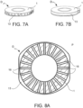
- a deformation and/or strain detecting washer device D will be now described making reference to figures 4-6 , 7A, 7B, 8A , 8B, 8C .
- Such washer device D comprises a device body 1, and an optical fiber 14 containing one or more fiber Bragg grating FBG type strain sensors.
- the device body 1 is shaped as a washer or a substantially disc-shaped plate which extends mainly along a radial reference plane p and has a first flat face 11 and a second flat face 12, parallel to the radial reference plane p, adapted to be placed in close contact with surfaces of fixing means and/or the brake caliper support 61 and/or the brake caliper body 60 so that they can be mounted at a fixing interface (i, ii, iii, iv) between brake caliper body 60 and brake caliper support 61, or between the brake caliper support 61 and a head of a clamping element 63, 64, or between an axle and a suspension of a vehicle wheel.
- a fixing interface i, ii, iii, iv
- the washer body 1 features a tangentially peripheral band (and/or recess) 13 which develops along a portion or perimeter of body 1 of the washer device D.
- the washer body 1 is susceptible to deformation when subjected to forces so that the deformation and/or force S locally present in each point of the washer device D is representative of the forces acting on the washer device D.
- the optical fiber 14 is arranged along or at the tangentially peripheral band 13.
- the optical fiber 14 contains one or more deformation and/or strain fiber Bragg grating fiber-optic strain sensor (FBG), each of which is configured to determine the local deformation and/or strain S acting in the respective detection position, and generating a respective at least one photonic signal L representative of the detected deformation and/or strain S.
- FBG strain fiber Bragg grating fiber-optic strain sensor
- Each of the aforesaid fiber-optic strain sensors FBG is obtained in a respective portion of optical fiber inclined with respect to a radial plane p at an acute or obtuse inclination angle different from each of the values 0°, 90°, 180° and 270°, to detect a strain S in a direction different from a normal direction and from a tangential direction and from a tangential or radial direction, with respect to said reference plane p of the washer, so that the detected strain S depends both on the normal component and on the tangential component of the force acting on the sensor and/or on each of the three spatial vector components of the force acting on the sensor.
- the optical fiber containing the fiber-optic strain sensor optical fiber FBG is adapted to transmit the aforesaid at least one photonic signal L generated by at least one fiber-optic strain sensor FBG and to receive at least one activation radiation OA intended for a respective at least one fiber-optic strain sensor FBG.
- the optical fiber 14 is connected to a protective output tube 35, allowing the connection of the device to the optical reading/ interrogation unit 4.
- the aforesaid angle of inclination is within the range of ⁇ 30° to ⁇ 45°.
- the aforesaid angle of inclination is ⁇ 30°.
- the aforesaid optical fiber comprises a plurality of fiber-optic strain sensors (FBG1, FBG2, FBG3, FBG4, FBG5, FBG6) arranged and/or equally spaced apart along the perimeter development of the optical fiber 14.
- FBG1, FBG2, FBG3, FBG4, FBG5, FBG6 fiber-optic strain sensors
- Each of the fiber-optic strain sensors (FBG1, FBG2, FBG3, FBG4, FBG5, FBG6) incorporated in a device D is made by means of a respective Bragg grating, associated with a respective central operating wavelength ( ⁇ 1, ⁇ 2, ⁇ 3, ⁇ 4, ⁇ 5, ⁇ 6), and is adapted to be energized by means of a respective optical radiation at the respective wavelength (belonging to an optical radiation of total energizing in wavelength-division multiplexing - WDM), and to generate a transmitted or reflected optical spectrum which constitutes the respective photonic signal (L1, L2, L3, L4, L5, L6).
- a respective Bragg grating associated with a respective central operating wavelength ( ⁇ 1, ⁇ 2, ⁇ 3, ⁇ 4, ⁇ 5, ⁇ 6)
- the aforesaid plurality of fiber-optic strain sensors FBG comprise six fiber-optic strain sensors (FBG1, FBG2, FBG3, FBG4, FBG5, FBG6).
- the central operating wavelengths of the six aforesaid fiber-optic strain sensors are 1535 nm, 1540 nm, 1545 nm, 1550 nm, 1555 nm, 1560 nm.
- each fiber-optic strain sensor FBG has a 1 mm long grating and 50% or more reflectivity; the six fiber-optic strain sensors are evenly spaced, with a distance of 14 mm from one another.
- the aforesaid optical fiber 14 further comprises a fiber-optic temperature sensor 5.
- the geometry of the body of the washer device D and the material of which the body of the washer device D is made are chosen as a function of the requirement to ensure mechanical strength to axial fixing preload and to the shearing force resulting from the braking action, and the requirement to optimize the deformation of the body of the washer device D without reaching critical structural strains.
- the body of the washer device D is made of steel, or titanium, or aluminum.
- the washer device D may consist of various parts which are bound together and/or various parts which can be mutually detached and reattached.
- body 1 of the washer device D may consist of various parts which are bound together and/or various parts which can be mutually detached and reattached.
- the body of the washer device D features ellipsoidal section recesses 15 along the annular recess at which the optical fiber containing the fiber-optic strain sensors is placed, and radial cavities 16 in the body of the washer device D having the aforesaid ellipsoidal recesses as their external ends.
- the perimeter of the washer device D features two opposite straight sides and two other opposite arc-of-circle-shaped sides.
- Figures 8A , 8B and 8C show, by means of sectional views, three specific design examples of a washer device D, developed for a steel, titanium, and aluminum device, respectively.
- the aluminum washer in figure 8C has no ellipsoidal end cavities.
- the first flat face 11 and the second flat face 12 of the device body 1 have a surface alteration which increases the friction between said first and second flat faces and the surfaces of the fixing equipment and/or the brake caliper support 61 and/or the brake caliper body 60, with which the aforesaid first and second flat faces are in contact, respectively, in operating conditions in which they are mounted at one of the aforesaid fixing interfaces (i, ii, iii, iv).
- the aforesaid surface alteration of the flat faces is obtained by means of a mechanical processing known in itself, for example, knurling.
- the aforesaid surface alteration of the flat faces is obtained by means of a "texturing" of the surface made with laser technology, or equivalent, in a manner known in itself, applicable on any metal surface, such as steel, titanium or aluminum.
- the aforesaid surface alteration of the flat faces is obtained by means of a coating.
- various processes may be used, such as the deposition of diamond particles, or silicon carbide, SiC, embedded in electrolytic nickel, or ESD (Electro-Spark Deposition) of tungsten carbide, stellite, or aluminum oxides if the substrate is aluminum or other known methods.
- the aforesaid surface alteration of the flat faces is obtained by means of finishing by mechanical removal, or machining by local deformation of the material (upsetting, knurling), or laser removal (or machining) which can lead to material vaporization, melting or combustion, or a variety of possible coating techniques, e.g., based on nanotechnology, very hard nanopowders which generate contact points with high exchange of forces and therefore high friction, hard inclusions which affect the surface locally creating "grips", or other.
- the effect of this embodiment is to remove or significantly reduce phenomena of local variation of the strains due to the reversal of the vehicle motion: indeed, by means of the measures taken, the friction coefficient on the interface surfaces is increased. By doing so, it is possible to either avoid or significantly reduce those micro-settings which, at the change between forward and reverse, change the local friction conditions and, consequently, the distribution of strains on the body surface of the washer device. This is very important because if local conditions change with each change of direction of the vehicle, the washer deforms differently and the output characteristic of the sensor is poorly repeatable and non-linear.
- the effects induced by the braking torque on the sensitive elements between forward and reverse conditions are standardized and made deterministic, thus improving the repeatability and linearity of the sensor output characteristic.
- a system 100 for determining a braking torque BT resulting from the actuation of a vehicle braking system, by detection performed at at least one fixing interface (i, ii, iii, iv) between a brake caliper body 60 and a respective support 61, or between the brake caliper support 61 and a head of a clamping element 63, 64, or between the axle and the wheel suspension will now be described making reference to figures 1-14 .
- the system 100 comprises at least a washer device D, according to any of the previously shown aforesaid embodiments, an optical reading/ interrogation unit 4 and a remote control unit 20.
- At least one washer device D is fixed and pressed between the brake caliper body 60 and the brake caliper support 61, at at least one said respective fixing interface (i, ii, iii, iv), or between the brake caliper support 61 and a clamping element head 63, 64, or between the axle and the wheel suspension.
- the optical reading/ interrogation unit 4 is optically connected to at least one washer device D to receive the aforesaid at least one photonic signal L.
- the optical reading/ interrogation unit 4 is configured to generate at least one electrical signal E representative of the detected deformation and/or strain S, based on at least one received first photonic signal L.
- the remote control unit 20 is connected to the optical reading/ interrogation unit 4 to receive the aforesaid at least one first electrical signal E and is configured to process the aforesaid at least one first electrical signal E representative of the deformation and/or strain S to obtain and provide a measurement of the braking torque BT.
- the system comprises a plurality of washer devices (D1, D2, D3, D4), each at a respective fixing interface (i, ii, iii, iv).
- each of the aforesaid washer devices incorporates a plurality of deformation and/or strain sensors (FBG1, FBG2, FBG3, FBG4, FBG5, FBG6).
- the remote control unit 20 is configured to determine the braking torque BT based on a plurality of electrical signals Ejk, each resulting from a respective photonic signal Ljk representative of a respective deformation and/or strain Sij, detected by a respective fiber-optic strain sensor.
- j is an index indicating one of the plurality of washer devices
- k is an index indicating one of the plurality of fiber-optic strain sensors comprised in the washer device.
- the system comprises: a first washer device D1 at a first fixing interface (i) between the head of a first fixing bolt 63 and a first portion of the caliper support 61; a second washer device D2 at a first fixing interface (ii) between the head of a second fixing bolt 64 and a second portion of the caliper support 61; a third washer device D3 at a third fixing interface (iii) between a third portion of the caliper support 61 and the caliper body 60; a fourth washer device D4 at a fourth fixing interface (iv) between a fourth portion of the caliper support 61 and the caliper body 60.
- the one or more fiber-optic strain sensors FBG are comprised in an optical fiber 14 arranged within a tangentially peripheral band 13 of the washer device.
- Each of such fiber-optic strain sensors FBG is obtained in a respective portion of optical fiber inclined with respect to a radial plane of the washer p (e.g., a plane of the sections in figures 8A , 8B, 8C ⁇ at an acute or obtuse inclination angle different from each of the values 0°, 90°, 180°, and 270°, to detect a strain S in a direction different from a normal direction and from a tangential direction, with respect to the washer, so that the detected strain S depends both on the normal component and on the tangential component of the force acting on the sensor.
- a radial plane of the washer p e.g., a plane of the sections in figures 8A , 8B, 8C ⁇ at an acute or obtuse inclination angle different from each of the values 0°, 90°, 180°, and 270°
- the system comprises at least one respective fiber-optic temperature sensor 5 of the fiber Bragg grating type incorporated in the at least one washer device D.
- the at least one temperature sensor 5 is configured to detect a temperature value T present in the respective position and to generate a respective at least one auxiliary photonic signal Lt representative of the measured temperature value T.
- the optical reading/interrogation unit 4 is optically connected to the at least one temperature sensor 5 and is configured to receive the at least one generated auxiliary photonic signal Lt, and to generate at least one auxiliary electrical signal Et representative of the temperature, based on at least one received auxiliary photonic signal Lt.
- the remote control unit 20 is configured to process at least one first electrical signal E and at least one auxiliary electrical signal Et to obtain a measurement of the braking force BT taking a temperature compensation into account.
- the aforesaid at least one temperature sensor 5 comprises a fiber Bragg grating made in the same optical fiber 14 in which the at least one deformation and/or strain sensor FBG is made.
- the fiber-optic strain sensor FBG is connected to the optical reading/ interrogation unit 4 by means of a first connection optical fiber 31.
- the optical reading/ interrogation unit 4 is configured to activate the fiber-optic temperature sensor by transmitting an optical activation radiation OA through the first connection optical fiber 31 and the second photonic signal L comprises an optical spectrum L reflected by the temperature sensor FBG, which reaches the optical reading/ interrogation unit 4 through the first connection optical fiber 31.
- the fiber-optic strain sensor FBG is connected to the optical reading/ interrogation unit 4 by means of a first input connection optical fiber 32 and a second output connection optical fiber 33.
- the optical reading/ interrogation unit 4 is configured to activate the aforesaid fiber-optic temperature sensor FBG transmitting an optical activation radiation OA through the first input connection optical fiber 32 and the second photonic signal L comprises a second optical spectrum L transmitted by the temperature sensor FBG of the fiber Bragg grating type, which reaches the optical reading/ interrogation unit 4 through said second output connection optical fiber 33.
- each of the fiber-optic strain sensors (FBG1, FBG2, FBG3, FBG4, FBG5, FBG6) of a device is made by means of a respective Bragg grating, associated with a respective central operating wavelength ( ⁇ 1, ⁇ 2, ⁇ 3, ⁇ 4, ⁇ 5, ⁇ 6).
- Each of the fiber-optic strain sensors (FBG1, FBG2, FBG3, FBG4, FBG5, FBG6) is configured to generate a respective at least one photonic signal of a plurality of photonic signals (L1, L2, L3, L4, L5, L6).
- the optical reading/interrogation unit 4 is configured to receive the plurality of photonic signals (L1, L2, L3, L4, L5, L6), and to generate at least one respective electrical signal (E) of a plurality of electrical signals (E1, E2, E3, E4, E5, E6), based on said plurality of received photonic signals (L1, L2, L3, L4, L5, L6);
- the remote control unit 20 is configured to process the aforesaid plurality of electrical signals (E1, E2, E3, E4, E5, E6) to obtain a measurement of the braking torque BT.
- the optical reading/ interrogation unit 4 is further configured to transmit through the connection optical fiber 3, respective optical activation radiations (OA1, OA2, OA3, OA4, OA5, OA6) to the plurality of deformation and/or strain elements, at different respective operating wavelengths ( ⁇ 1, ⁇ 2, ⁇ 3, ⁇ 4, ⁇ 5, ⁇ 6), by means of wavelength-division multiplexing (WDM) transmission techniques; and to receive, through the connection optical fiber 3, and distinguishing the respective optical spectra reflected by each of the plurality of deformation and/or strain sensors (FBG1, FBG2, FBG3, FBG4, FBG5, FBG6), by means of de-multiplexing with wavelength-division multiplexing (WDM) techniques, wherein each of said optical reflected spectra corresponds to a respective photonic signal (L1, L2, L3, L4, L5, L6).
- WDM wavelength-division multiplexing
- control unit 20 comprises a processor configured to calculate the braking torque BT by means of one or more algorithms executed by one or more software programs, based on the aforesaid at least one electrical signal E or based on the aforesaid at least one electrical signal E and said auxiliary electrical signal Et, or based on the aforesaid plurality of electrical signals (Ea, E1, E2, E3, E4, E5, E6; Eij) and of the aforesaid at least one auxiliary electrical signal Et.
- a processor configured to calculate the braking torque BT by means of one or more algorithms executed by one or more software programs, based on the aforesaid at least one electrical signal E or based on the aforesaid at least one electrical signal E and said auxiliary electrical signal Et, or based on the aforesaid plurality of electrical signals (Ea, E1, E2, E3, E4, E5, E6; Eij) and of the aforesaid at least one auxiliary electrical signal Et.
- the remote control unit 20 is configured to determine the braking torque BT, based on the electrical signals E representative of the detected strains S, through the algorithms and/or procedures previously described illustrating the method according to the invention.
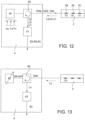
- the optical reading/ interrogation unit 4 comprises a broadband optical radiation source 40, an optical circulator 46, and an opto-electronic spectrometer receiver 41.
- the broadband optical radiation source 40 is configured to transmit a first activation optical radiation OA or a plurality of second activation optical radiations OAa, OAb, OAc and/or the second activation optical radiation OAt.
- the opto-electronic spectrometer receiver 41 is configured to select the wavelength and/or the plurality of wavelengths to be received and is also configured to receive the aforesaid first photonic signal L, or the aforesaid plurality of first photonic signals La, Lb, Lc and convert them into the first electric signal E, or the plurality of first electric signals Ea, Eb, Ec, and/or to receive the aforesaid second photonic signal Lt and convert it into the second electric signal Et.
- multiplexed FBG sensors in the wavelength domain are queried using a technique based on a broad spectrum source and spectrometer (as shown in figure 12 ).
- the broad-spectrum source may comprise, for example, a super-luminescent diode or a spontaneous emission source (such as a semiconductor optical amplifier or an erbium-doped fiber optical amplifier) and is used to illuminate (through the input port and the through port of the optical circulator 46) the FBG sensors 2a, 2b, 2c characterized by reflectivity peaks at different wavelengths ( ⁇ a, ⁇ b, ⁇ c) not superimposed on each other.
- a super-luminescent diode or a spontaneous emission source (such as a semiconductor optical amplifier or an erbium-doped fiber optical amplifier) and is used to illuminate (through the input port and the through port of the optical circulator 46) the FBG sensors 2a, 2b, 2c characterized by reflectivity peaks at different wavelengths ( ⁇ a, ⁇ b, ⁇ c) not superimposed on each other.
- the different photonic signals La, Lb, Lc, at their respective wavelengths, are retroreflected by FBG sensors (in the example shown in figure 12 ) and are coupled to a spectrometer 41 through the output port of the optical circulator 46.
- the spectrometer 41 is, for example, a dispersive element, typically made by means of a Phase Grating Volume, able to spatially separate the different spectral components of the signal. Such spatially separated signal components are coupled to an array of photo-receivers capable of generating signals with intensity values corresponding to the various wavelengths.
- Each photo-receiver is sensitive to optical radiation corresponding to a well-defined spectral region, thus providing the possibility to reconstruct the entire spectrum, in the spectral range of interest.
- the optical reading/ interrogation unit 4 comprises a tunable optical radiation source 42, an optical circulator 46, and a photo-diode opto-electronic receiver 43.
- the tunable optical radiation source 42 is configured to transmit the desired optical radiation OAn (at the respective wavelength ⁇ n) between the possible first optical activation radiation OAa, OAb, OAc, or the second optical activation radiation OAt, at wavelength ⁇ t, at a given time.
- the emitted optical radiation OAn illuminates (through the input port and the through port of the optical circulator 46) the optical fiber containing the FBG sensors, and determines a response by the FBG sensors sensitive to the wavelength ⁇ 1, which generates a recto-reflected photonic signal Ln, which is coupled to the photo-diode receiver 43 through the output port of the optical circulator 46.
- the photo-diode opto-electronic receiver 43 configured to receive the first photonic signal Ln and convert it into a first electrical signal En (or similarly to receive the second photonic signal Lt and convert it into said second electrical signal Et).
- multiplexed FBG sensors in the wavelength domain are interrogated using a tunable laser and photo-diode based technique.
- the tunable optical radiation source 42 is a tunable laser, used in the known "agile tunable” or “swept wavelength” modes.
- the optical reading/ interrogation unit 4 is entirely made by means of a single photonic integrated circuit using PIC technology.
- a single integrated photonic circuit comprises a broadband optical radiation source 40, at least one wavelength optical filtering element 44, and an opto-electronic photo-diode receiver 43.
- the broadband optical radiation source 40 is configured to transmit a first activation optical radiation OA or a plurality of second activation optical radiations OAa, OAb, OAc and/or the second activation optical radiation OAt.
- the emitted optical radiation (which comprises, in the example of figure 14 , the optical radiations OAa, OAb, OAc), through the input port and the through port of the optical circulator 46, illuminates the optical fiber containing the FBG sensors, each of which reflects a respective photonic signal La, Lb, Lc.
- the at least one wavelength optical filtering element 44 can be tuned in the surround of the wavelength of the interrogated fiber Bragg grating, in order to select a respective photonic signal (the photonic signal Lb at the wavelength ⁇ b in the example in figure 14 ).
- the optical filtering element 44 being tunable, can be tuned to different wavelengths, in order to select in sequence or at different times according to what is desired, the photonic signal reflected by any one of the FBG sensors.
- the opto-electronic photo-diode 43 receiver is configured to receive the photonic signal selected among the aforesaid photonic signals and convert it into one or more electrical signals, and/or to receive the second photonic signal Lt, if selected, and convert it into the second electrical signal Et.
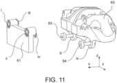
- a sensorized brake caliper 6 for a vehicle braking system is described below with reference to figures 9, 10 , 11 .
- the sensorized brake caliper 6 comprises a brake caliper body 60, a brake caliper support 61, a first fixing bolt 63 and a second fixing bolt 64, and at least one washer device D according to any of the embodiments described above.
- the at least one washer device D is fixed and pressed between the brake caliper body 60 and the brake caliper support 61 at at least one fixing interface (i, ii, iii, iv) between the brake caliper body 60 and the brake caliper support 61.
- the brake caliper is a fixed or floating brake caliper.
- the sensorized caliper 6 further comprises an optical reading/ interrogation unit 4, which can be connected to a remote control unit 20 external to the brake caliper.
- the optical reading/ interrogation unit 4 is according to what is described above.
- said optical reading/ interrogation unit 4 is optically connected to first photonic connection means 3 to receive at least one photonic signal L and is configured to determine at least one electrical signal E representative of the detected deformation and/or strain S based on at least one received photonic signal L.
- the aforesaid at least one electrical signal E is adapted to be transmitted to the remote control unit 20.
- the sensorized brake caliper 6 comprises: a first washer device D1 at a first fixing interface (i) between the head of a first fixing bolt 63 and a first portion of the caliper support 61; a second washer device D2 at a first fixing interface (ii) between the head of a second fixing bolt 64 and a second portion of the caliper support 6; a third washer device D3 at a third fixing interface (iii) between a third portion of the caliper support 61 and the caliper body 60; a fourth washer device D4 at a fourth fixing interface (iv) between a fourth portion of the caliper support 61 and the caliper body 60.
- the brake caliper is a disc brake caliper, fixed or floating, or a caliper with radial and axial connections, or mono-bloc or floating caliper, or hydraulic or electro-actuated caliper.
- the optical reading/ interrogation unit 4 is integrated and/or housed in the sensorized caliper 6.
- electrical signals E are output from the sensorized caliper and directed to the remote control unit.
- the optical reading/ interrogation unit 4 is external to the sensorized brake caliper 6.
- photonic signals L are emitted from the sensorized caliper, on fiber, directed towards the optical reading/ interrogation unit 4.
- the sensorized brake caliper comprises a positioning element 62 of the washer devices D adapted to retain and position one or more washer devices D in the correct position.
- F n-iii and F n-iv are normal forces exchanged between the brake caliper and brake caliper support and due to the action of bolts 63 and 64, respectively.
- F n-i and F n-ii are the normal forces exchanged between the head of each bolt and the brake caliper support.
- the moments of the torques on the z-y plan (M z-i , M z-ii , M z-iii , M z-iv , M y-i , M >y-ii , M y-iii , M y-iv ) are generated by normal force distributions on each contact interface.
- the invention also encompasses a vehicle braking system, comprising a plurality of sensorized brake calipers 6 according to any one of the embodiments of sensorized calipers described above.
- the invention further comprises a vehicle braking system comprising a system 100 for determining a braking torque BT resulting from the implementation of a vehicle braking system according to any one of the embodiments for determining a braking torque BT described above.
- the invention further comprises a manufacturing method of a washer device D according to any one of the embodiments shown above.
- Such manufacturing method comprises the steps of positioning on the side surface of the washer of the washer device D an optical fiber 14 previously prepared by inscribing the fiber-optic strain sensors (FBG) arranged according to a pre-determined spacing; positioning each portion of fiber inscribed with a respective strain sensor FBG in a respective inclined direction, at a predetermined inclination angle with respect to a radial reference plane p of the washer, along the side surface of the washer; fixing a shaped box to the washer and to the optical fiber to protect and orient the outgoing fiber; fixing the optical fiber 14 and its inclined fiber portions comprising the fiber-optic strain sensors FBG on the side band of the washer and in the output box with binder material; applying a protective layer around the peripheral side band of the washer in which the optical fiber 14 is arranged.
- FBG fiber-optic strain sensors
- the aforesaid manufacturing method comprises the further step of modifying the first flat face 11 and the second flat face 12 of the device body 1 by means of a surface alteration adapted to increase the friction between the aforesaid first and second flat faces and the surfaces of the fixing equipment and/or support of the brake caliper 61 and/or brake caliper body 60, with which the aforesaid first and second flat faces are in contact, respectively, in operating conditions in which they are mounted at one of the fixing interfaces (i, ii, iii, iv).
- the aforesaid surface alteration of the first flat face 11 and the second flat face 12 is achieved by mechanical processing, for example knurling, or "texturing" the surface using laser technology or the like; or a surface coating.
- the detecting washer device shown above can detect deformations and/or forces representative of the forces acting at a clamping interface between a brake caliper body and its support, and/or between brake caliper support and axle, which in turn depend on the braking torque simultaneously, and with good accuracy.
- the detecting washer device can detect both the tangential component and the normal component (or, even more specifically, the three vector components) of the forces acting on it.
- such device by virtue of its small size and its "washer" shape, can be advantageously and easily inserted between the apparatus of a wheel and the axle of a vehicle (in particular, between a brake caliper and a brake caliper support), using already provided fixing means, for example, the screws already provided for the attachment of the brake caliper to its support, one or more attachment points.
- the device with respect to the brake caliper.
- this allows great versatility of use, permitting a wide variety of structural options, and on the other hand it provides degrees of freedom to achieve different levels of accuracy according to the requirements: for example, the solutions with a plurality of devices, arranged in different points, and each with a plurality of fiber-optic sensors inside, offers a greater quantity of detections and of respective electrical signals to the control system, allowing more precise processing and estimates.
- the system comprises one or more sensorized brake calipers which include fiber-optic sensors, optically connected to a reading/ interrogation unit (which can be remote or also integrated into the brake caliper) for an opto-electronic conversion of the strain information, which, advantageously, can also be based on WDM techniques.
- the reading/ interrogation unit can be made based on different electro-optical technologies.
- such reading/ interrogation unit can be made by means of silicon-based photonic technologies (e.g., PIC: Photonics Integrated Circuit), which allows making such unit also by integrating it in the sensorized brake caliper.
- silicon-based photonic technologies e.g., PIC: Photonics Integrated Circuit
- the control unit of the system can thus determine the braking torque, with temperature compensation, and over a wide operating range.
Landscapes
- Engineering & Computer Science (AREA)
- Physics & Mathematics (AREA)
- General Physics & Mathematics (AREA)
- Mechanical Engineering (AREA)
- General Engineering & Computer Science (AREA)
- Transportation (AREA)
- Chemical & Material Sciences (AREA)
- Analytical Chemistry (AREA)
- Length Measuring Devices By Optical Means (AREA)
- Force Measurement Appropriate To Specific Purposes (AREA)
- Braking Arrangements (AREA)
Claims (20)
- Verfahren zum Bestimmen eines aus der Betätigung eines Bremssystems für ein Fahrzeug resultierenden Bremsmoments (BT) mittels einer Detektion, welche an wenigstens einer Befestigungsschnittstelle (i, ii, iii, iv) zwischen einem Bremssattelkörper (60) und einer jeweiligen Halterung (61) oder zwischen einer Achse und einer Radaufhängung durchgeführt wird, wobei das Verfahren die folgenden Schritte umfasst:- Einfügen wenigstens einer Scheibenvorrichtung (D) an der wenigstens einen Befestigungsschnittstelle (i, ii, iii, iv), so dass die Scheibenvorrichtung (D) zwischen dem Bremssattelkörper (60) und der Bremssattelhalterung (61) oder zwischen der Bremssattelhalterung (61) und einem Kopf eines Klemmelements (63, 64) befestigt und dazwischen gedrückt ist, oder zwischen der Achse und der Radaufhängung,wobei die Scheibenvorrichtung (D) einer Verformung unterliegt, wenn sie Kräften ausgesetzt ist, so dass die Verformung und/oder Dehnung (S), welche an jeder Stelle der Scheibenvorrichtung (D) lokal vorhanden ist, für die Kräfte repräsentativ ist, welche abhängig von dem Bremsmoment (BT) an der wenigstens einen Befestigungsschnittstelle wirken,wobei die Scheibenvorrichtung (D) an einer jeweiligen Detektionsposition wenigstens einen Verformungs- und/oder Dehnungssensor (FBG) enthält, welcher dazu eingerichtet ist, eine Verformung und/oder eine Dehnung zu detektieren, welche für die drei räumlichen Vektorkomponenten der Kraft repräsentativ ist, die an der Detektionsposition auf die Scheibenvorrichtung (D) wirkt, wobei der wenigstens eine Verformungs- und/oder Dehnungssensor (FBG) ein faseroptischer Dehnungssensor (FBG) vom Typ Faser-Bragg-Gitter ist;- Detektieren, mittels jedes des wenigstens einen faseroptischen Dehnungssensors (FBG), der lokalen Verformung und/oder Dehnung (S), welche in der jeweiligen Detektionsposition wirkt, und Erzeugen eines jeweiligen wenigstens einen photonischen Signals (L), welches für die detektierte Verformung und/oder Dehnung (S) repräsentativ ist;- Empfangen des wenigstens einen photonischen Signals (L) durch eine optische Lese-/Abfrageeinheit (4), welche optisch mit dem wenigstens einen faseroptischen Dehnungssensor (FBG) verbunden ist;- Erzeugen, durch die optische Lese-/Abfrageeinheit (4), wenigstens eines elektrischen Signals (E), welches für die lokal detektierte Verformung und/oder Dehnung (S) repräsentativ ist, auf der Grundlage des wenigstens einen empfangenen photonischen Signals (L);- Bestimmen des Bremsmoments (BT) auf der Grundlage des wenigstens einen elektrischen Signals (E), welches für die Verformung und/oder Dehnung (S) repräsentativ ist;wobei der eine oder die mehreren faseroptischen Dehnungssensoren (FBG) in einer optischen Faser (14) umfasst sind, welche innerhalb eines tangentialen peripheren Bands (13) der Scheibenvorrichtung (D) angeordnet ist,
und wobei jeder dieser faseroptischen Dehnungssensoren (FBG) in einem jeweiligen Abschnitt der optischen Faser erhalten ist, welcher in Bezug auf eine radiale Ebene der Scheibe (p) in einem spitzen oder stumpfen Neigungswinkel geneigt ist, der von jedem der Werte 0°, 90°, 180° und 270° verschieden ist, um eine Dehnung (S) in einer Richtung zu detektieren, welche von einer normalen Richtung und von einer tangentialen Richtung in Bezug auf die Scheibe verschieden ist, so dass die detektierte Dehnung (S) sowohl von der normalen Komponente als auch von der tangentialen Komponente der Kraft abhängt, welche auf den Sensor wirkt. - Verfahren nach Anspruch 1, wobei der Schritt des Einfügens ein Einfügen einer Mehrzahl von Scheibenvorrichtungen (D1, D2, D3, D4), jede an einer jeweiligen Befestigungsschnittstelle (i, ii, iii, iv), umfasst, und wobei jede der Scheibenvorrichtungen eine Mehrzahl von Verformungs- und/oder Dehnungssensoren (FBG1, FBG2, FBG3, FBG4, FBG5, FBG6) enthält;
und wobei der Schritt des Bestimmens ein Bestimmen des Bremsmoments (BT) auf der Grundlage einer Mehrzahl von elektrischen Signalen (Ejk) umfasst, welche jeweils von einem jeweiligen photonischen Signal (Ljk) abgeleitet sind, welches für eine jeweilige Verformung und/oder Dehnung (Sij) repräsentativ ist, welche durch einen jeweiligen faseroptischen Dehnungssensor detektiert worden ist, wobei j ein Index ist, welcher eine der Mehrzahl von Scheibenvorrichtungen anzeigt, und k ein Index ist, welcher einen der Mehrzahl von faseroptischen Dehnungssensoren anzeigt, welche in der Scheibenvorrichtung umfasst sind. - Verfahren nach Anspruch 2, wobei der Schritt des Einfügens umfasst:- Einfügen einer ersten Scheibenvorrichtung (D1) an einer ersten Befestigungsschnittstelle (i) zwischen dem Kopf eines ersten Befestigungsbolzens (63) und einem ersten Abschnitt der Sattelhalterung (61);- Einfügen einer zweiten Scheibenvorrichtung (D2) an einer ersten Befestigungsschnittstelle (ii) zwischen dem Kopf eines zweiten Befestigungsbolzens (64) und einem zweiten Abschnitt der Sattelhalterung (61);- Einfügen einer dritten Scheibenvorrichtung (D3) an einer dritten Befestigungsschnittstelle (iii) zwischen einem dritten Abschnitt der Sattelhalterung (61) und dem Sattelkörper (60);- Einfügen einer vierten Scheibenvorrichtung (D4) an einer vierten Befestigungsschnittstelle (iv) zwischen einem vierten Abschnitt der Sattelhalterung (61) und dem Sattelkörper (60).
- Verfahren nach einem der vorhergehenden Ansprüche, umfassend die folgenden weiteren Schritte:- Einbinden wenigstens eines jeweiligen faseroptischen Temperatursensors (5) vom Typ Faser-Bragg-Gitter in der wenigstens einen Scheibenvorrichtung (D);- Detektieren, mittels jedes des wenigstens einen Temperatursensors (5), eines Temperaturwerts (T), welcher in der jeweiligen Position vorhanden ist, und Erzeugen eines jeweiligen wenigstens einen photonischen Hilfssignals (Lt), welches für den gemessenen Temperaturwert (T) repräsentativ ist;- Empfangen des wenigstens einen erzeugten photonischen Hilfssignals (Lt) durch die optische Lese-/Abfrageeinheit (4), welche optisch mit dem wenigstens einen Temperatursensor (5) verbunden ist;- Erzeugen, durch die optische Lese-/Abfrageeinheit (4), wenigstens eines elektrischen Hilfssignals (Et), welches für die Temperatur repräsentativ ist, auf der Grundlage des wenigstens einen empfangenen photonischen Hilfssignals (Lt);und wobei der Schritt des Bestimmens ein Verarbeiten des wenigstens einen ersten elektrischen Signals (E) und des wenigstens einen elektrischen Hilfssignals (Et) umfasst, um unter Berücksichtigung einer Temperaturkompensation eine Messung des Bremsmoments (BT) zu erhalten, und wobei der wenigstens eine Temperatursensor (5) ein Faser-Bragg-Gitter umfasst, welches in der gleichen optischen Faser (14) ausgeführt ist, in welcher der wenigstens eine Verformungs- und/oder Dehnungssensor (FBG) ausgeführt ist.
- Verfahren nach einem der vorhergehenden Ansprüche, umfassend, vor dem Schritt des Bestimmens, den Schritt eines Übertragens des wenigstens einen elektrischen Signals (E) und/oder elektrischen Hilfssignals (Et) an eine Steuereinheit (20);und wobei der Schritt des Bestimmens umfasst:- Berechnen des Bremsmoments (BT) durch einen Prozessor der Steuereinheit (20) mittels eines oder mehrerer Algorithmen, welche durch ein oder mehrere SoftwareProgramme ausgeführt werden, auf der Grundlage des wenigstens einen elektrischen Signals (E) oder auf der Grundlage des wenigstens einen ersten elektrischen Signals (E) und des elektrischen Hilfssignals (Et), oder auf der Grundlage der Mehrzahl von elektrischen Signalen (Ea, E1, E2, E3, E4, E5, E6; Eij) und des wenigstens einen elektrischen Hilfssignals (Et);
wobei der Schritt des Berechnens ein Berechnen des Bremsmoments (BT) mittels vordefinierter nicht linearer Beziehungen zwischen dem Bremsmoment und der Verformung und/oder Dehnung umfasst, welche durch wenigstens einen Verformungs- und/oder Dehnungssensor (FBG) in der jeweiligen Position detektiert worden ist, in welcher er in der Scheibenvorrichtung (D) enthalten ist,wobei die vorbestimmten nicht linearen Beziehungen durch computergestützte Modelle oder Nachschlagtabellen repräsentiert sind, welche derart gespeichert sind, dass sie für den Prozessor der Steuereinheit (20) zugänglich sind,wobei die vordefinierten nicht linearen Beziehungen mittels Test- und/oder Charakterisierungs- und/oder Kalibrierungsphasen bestimmt werden, welche durchgeführt werden, nachdem wenigstens eine Scheibenvorrichtung (D), welche wenigstens einen Verformungs- und/oder Dehnungssensor (D) enthält, an einer jeweiligen Befestigungsschnittstelle zwischen dem Bremssattelkörper und der Bremssattelhalterung platziert und befestigt worden ist. - Verfahren nach den Ansprüchen 2 und 5, wobei der Schritt des Berechnens umfasst:- Definieren, für jede der vier Scheibenvorrichtungen (D1, D2, D3, D4), eines jeweiligen nicht linearen Modells (NM1, NM2, NM3, NM4), welches dazu eingerichtet ist, die drei Vektorkomponenten der jeweiligen auf die Scheibenvorrichtung wirkenden Vektorkraft, d. h., dreiachsige Kraft (F1, F2, F3, F4), zu bestimmen;- Berechnen des Bremsmoments (BT) auf der Grundlage der dreiachsigen Kräfte (F1, F2, F3, F4), wobei der Schritt des Definierens eines nicht linearen Modells für eine Scheibenvorrichtung umfasst:- Definieren eines grundlegenden nicht linearen Modells mittels einer FEM-Simulation;- Präzisieren der Parameter des nicht linearen Modells mittels einer anfänglichen Kalibrierungsphase auf der Grundlage von durch die jeweiligen faseroptischen Dehnungssensoren der Scheibenvorrichtung detektierten Dehnungsmessungen (Sij) und gleichzeitigen Messungen der physikalischen Größen, welche die Dehnungen (Sij) erzeugen, unter bekannten experimentellen Bedingungen,wobei die physikalischen Größen das Bremsmoment (BT), die Vorlast aufgrund der Spannung der Befestigungsschraube bei einer Montage (V) und/oder den durch den Bremssattel aufgebrachten Druck (P) umfassen.
- Scheibenvorrichtung (D) zum Detektieren einer Verformung und/oder einer Dehnung, umfassend:- einen Vorrichtungskörper (1), in der Form einer Scheibe oder einer im Wesentlichen scheibenförmigen Platte, welche sich hauptsächlich entlang einer radialen Referenzebene (p) erstreckt, welcher eine erste flache Fläche (11) und eine zweite flache Fläche (12) aufweist, welche parallel zu der radialen Referenzebene (p) sind und dazu eingerichtet sind, in engem Kontakt mit Oberflächen von Befestigungsmitteln und/oder der Bremssattelhalterung (61) und/oder des Bremssattelkörpers (60) platziert zu sein, um an einer Befestigungsschnittstelle (i, ii, iii, iv) zwischen dem Bremssattelkörper (60) und der Bremssattelhalterung (61) oder zwischen der Bremssattelhalterung (61) und einem Kopf eines Klemmelements (63, 64) montiert zu sein,wobei der Vorrichtungskörper (1) ein tangential peripheres Band und/oder eine tangential periphere Ausnehmung (13) umfasst, welches/welche sich entlang eines Abschnitts oder eines Umfangs des Vorrichtungskörpers (1) der Scheibenvorrichtung (D) erstreckt,wobei der Körper (1) einer Verformung unterliegt, wenn er Kräften ausgesetzt ist, so dass die Verformung und/oder Dehnung (S), welche an jeder Stelle der Scheibenvorrichtung (D) lokal vorhanden ist, für die Kräfte repräsentativ ist, welche an der Scheibenvorrichtung (D) wirken,- eine optische Faser (14), welche entweder entlang oder an dem tangential peripheren Band und/oder der tangential peripheren Ausnehmung (13) angeordnet ist, wobei die optische Faser (14) einen oder mehrere Verformungs- und/oder Dehnungssensoren vom Typ Faser-Bragg-Gitter (FBG) enthält, wobei jeder des einen oder der mehreren faseroptischen Verformungs- und/oder Dehnungssensoren vom Typ Faser-Bragg-Gitter (FBG) dazu eingerichtet ist, die lokale Verformung und/oder Dehnung (S) zu detektieren, welche in der jeweiligen Detektionsposition wirkt, und ein jeweiliges wenigstens eines photonisches Signal (L) zu erzeugen, welches für die detektierte Verformung und/oder Dehnung (S) repräsentativ ist,
wobei jeder der faseroptischen Dehnungssensoren (FBG) in einem jeweiligen Abschnitt der optischen Faser erhalten ist, welcher in Bezug auf eine radiale Ebene (p) in einem spitzen oder stumpfen Neigungswinkel geneigt ist, der von jedem der Werte 0°, 90°, 180° und 270° verschieden ist, um eine Dehnung (S) in einer Richtung zu detektieren, welche von einer normalen Richtung und von einer tangentialen Richtung und von einer tangentialen oder radialen Richtung in Bezug auf die Referenzebene (p) der Scheibe verschieden ist, so dass die detektierte Dehnung (S) sowohl von der normalen Komponente als auch von der tangentialen Komponente der Kraft, welche auf den Sensor wirkt, und/oder von jeder der drei räumlichen Vektorkomponenten der Kraft abhängt, welche auf den Sensor wirkt;- wobei die optische Faser (14), welche die faseroptischen Dehnungssensoren (FBG) enthält, dazu eingerichtet ist, das durch den wenigstens einen faseroptischen Dehnungssensor (FBG) erzeugte wenigstens eine photonische Signal (L) zu übertragen, und wenigstens eine Aktivierungsstrahlung (OA) zu empfangen, welche für einen jeweiligen wenigstens einen faseroptischen Dehnungssensor (FBG) gedacht ist. - Vorrichtung nach Anspruch 7, wobei die optische Faser eine Mehrzahl von faseroptischen Dehnungssensoren (FBG1, FBG2, FBG3, FBG4, FBG5, FBG6) umfasst, welche entlang der Umfangserstreckung der optischen Faser (14) angeordnet und/oder gleichmäßig beabstandet sind,
wobei jeder der faseroptischen Dehnungssensoren (FBG1, FBG2, FBG3, FBG4, FBG5, FBG6) einer Vorrichtung (D) mittels eines jeweiligen Bragg-Gitters ausgeführt ist, welches einer jeweiligen zentralen Betriebswellenlänge (λ1, λ2, λ3, λ4, λ5, λ6) zugeordnet ist und dazu eingerichtet ist, mittels einer jeweiligen optischen Strahlung mit der jeweiligen Wellenlänge angeregt zu werden, welche in einem Wellenlängenmultiplexverfahren zu einer optischen Gesamtanregungsstrahlung gehört, und ein übertragenes oder reflektiertes optisches Spektrum zu erzeugen, welches das jeweilige photonische Signal (L1, L2, L3, L4, L5, L6) bildet. - Vorrichtung nach Anspruch 8, wobei die Mehrzahl von faseroptischen Dehnungssensoren (FBG) sechs faseroptische Dehnungssensoren (FBG1, FBG2, FBG3, FBG4, FBG5, FBG6) umfasst oder sechs faseroptische Dehnungssensoren (FBG1, FBG2, FBG3, FBG4, FBG5, FBG6) und einen faseroptischen Temperatursensor (5) umfasst,
und/oder wobei der Neigungswinkel ± 30° beträgt. - Vorrichtung nach einem der Ansprüche 7-9, wobei die Geometrie des Körpers der Scheibenvorrichtung (D) und das Material, aus welchem der Körper der Scheibenvorrichtung (D) hergestellt ist, als eine Funktion der Anforderung, um einer mechanische Festigkeit gegen axiale Befestigungsvorspannungen und gegen die aus der Bremswirkung resultierenden Scherkräfte zu gewährleisten, und der Anforderung ausgewählt sind, um die Verformung des Vorrichtungskörpers der Scheibenvorrichtung (D) zu optimieren, ohne kritische strukturelle Dehnungen zu erreichen;
und/oderwobei der Körper der Scheibenvorrichtung (D) aus Stahl, Titan oder Aluminium hergestellt ist,
und/oder wobei der Körper (1) der Scheibenvorrichtung (D) aus verschiedenen Teilen, welche miteinander verbunden sind, und/oder verschiedenen Teilen besteht, welche gegenseitig voneinander gelöst und wieder aneinander angebracht werden können;
und/oderwobei der Körper der Scheibenvorrichtung (D) entlang der ringförmigen Ausnehmung, in welcher die optische Faser platziert ist, welche die faseroptischen Dehnungssensoren enthält, ellipsenförmige Sektionsausnehmungen (15) aufweist und wobei radiale Hohlräume (16) in dem Körper der Scheibenvorrichtung (D) die ellipsenförmigen Ausnehmungen als ihre äußeren Enden aufweisen,
und wobei der Umfang der Scheibenvorrichtung (D) zwei entgegengesetzte gerade Seiten und zwei andere entgegengesetzte kreisbogenförmige Seiten aufweist. - Vorrichtung nach einem der Ansprüche 7-10, wobei die erste flache Fläche (10) und die zweite flache Fläche (12) des Körpers der Vorrichtung (1) eine Oberflächenveränderung aufweisen, welche dazu eingerichtet ist, die Reibung zwischen der ersten und der zweiten flachen Fläche und den Oberflächen der Befestigungsmittel und/oder der Bremssattelhalterung (61) und/oder des Bremssattelkörpers (60) zu erhöhen, mit welchen die erste und die zweite flache Fläche unter Betriebsbedingungen, in welchen sie an einer der Befestigungsschnittstellen (i, ii, iii, iv) montiert sind, jeweils in Kontakt sind,
wobei die Oberflächenveränderung der ersten flachen Fläche (11) und der zweiten flachen Fläche (12) erhalten wird, mittels:- einer mechanischen Nachbearbeitung, zum Beispiel einer Rändelung; oder- einer Texturierung der mittels einer Lasertechnologie oder dergleichen erhaltenen Oberfläche; oder- einer Beschichtung. - System (100) zum Bestimmen eines aus der Betätigung eines Bremssystems für ein Fahrzeug resultierenden Bremsmoments (BT) mittels einer Detektion, welche an wenigstens einer Befestigungsschnittstelle (i, ii, iii, iv) zwischen einem Bremssattelkörper (60) und einer jeweiligen Halterung (61) oder zwischen der Bremssattelhalterung (61) und einem Kopf eines Klemmelements (63, 64) oder zwischen der Achse und der Radaufhängung durchgeführt wird,
wobei das System (100) umfasst:- wenigstens eine Scheibenvorrichtung (D) nach einem der Ansprüche 7-11, wobei die wenigstens eine Scheibenvorrichtung (D) an der jeweiligen wenigstens einen Befestigungsschnittstelle (i, ii, iii, iv) oder zwischen der Achse und der Radaufhängung zwischen dem Bremssattelkörper (60) und der Bremssattelhalterung (61) oder zwischen der Bremssattelhalterung (61) und einem Kopf eines Klemmelements (63, 64) befestigt und dazwischen gedrückt ist,- eine optische Lese-/Abfrageeinheit (4), welche optisch mit wenigstens einer Scheibenvorrichtung (D) verbunden ist, um das wenigstens eine photonische Signal (L) zu empfangen,
wobei die optische Lese-/Abfrageeinheit (4) dazu eingerichtet ist, auf der Grundlage des wenigstens einen empfangenen photonischen Signals (L) wenigstens ein elektrisches Signal (E) zu erzeugen, welches für die detektierte Verformung und/oder Dehnung (S) repräsentativ ist;- eine Fernsteuereinheit (20), welche mit der optischen Lese-/Abfrageeinheit (4) verbunden ist, um das wenigstens eine elektrische Signal (E) zu empfangen,wobei die Fernsteuereinheit (20) dazu eingerichtet ist, das wenigstens eine elektrische Signal (E) zu verarbeiten, welches für die Verformung und/oder Dehnung (S) repräsentativ ist, um eine Messung des Bremsmoments (BT) zu erhalten und bereitzustellen. - System nach Anspruch 12, umfassend eine Mehrzahl von Scheibenvorrichtungen (D1, D2, D3, D4), jede an einer jeweiligen Befestigungsschnittstelle (i, ii, iii, iv) davon, wobei jede der Scheibenvorrichtungen eine Mehrzahl von Verformungs- und/oder Dehnungssensoren (FBG1, FBG2, FBG3, FBG4, FBG5, FBG6) enthält,
oder umfasst:- eine erste Scheibenvorrichtung (D1) an einer ersten Befestigungsschnittstelle (i) zwischen dem Kopf eines ersten Befestigungsbolzens (63) und einem ersten Abschnitt der Sattelhalterung (61);- eine zweite Scheibenvorrichtung (D2) an einer ersten Befestigungsschnittstelle (ii) zwischen dem Kopf eines zweiten Befestigungsbolzens (64) und einem zweiten Abschnitt der Sattelhalterung (61);- eine dritte Scheibenvorrichtung (D3) an einer dritten Befestigungsschnittstelle (iii) zwischen einem dritten Abschnitt der Sattelhalterung (61) und dem Sattelkörper (60);- eine vierte Scheibenvorrichtung (D4) an einer vierten Befestigungsschnittstelle (iv) zwischen einem vierten Abschnitt der Sattelhalterung (61) und dem Sattelkörper (60);und wobei die Fernsteuereinheit (20) dazu eingerichtet ist, das Bremsmoment (BT) auf der Grundlage einer Mehrzahl von elektrischen Signalen (Ejk) zu bestimmen, welche jeweils von einem jeweiligen photonischen Signal (Ljk) abgeleitet sind, welches für eine jeweilige Verformung und/oder Dehnung (Sij) repräsentativ ist, welche durch einen jeweiligen faseroptischen Dehnungssensor detektiert worden ist, wobei j ein Index ist, welcher eine der Mehrzahl von Scheibenvorrichtungen anzeigt, und k ein Index ist, welcher einen der Mehrzahl von faseroptischen Dehnungssensoren anzeigt, welche in der Scheibenvorrichtung umfasst sind. - System nach einem der Ansprüche 12-13, ferner umfassend wenigstens einen jeweiligen faseroptischen Temperatursensor (5) vom Typ Faser-Bragg-Gitter, welcher in der wenigstens einen Scheibenvorrichtung (D) enthalten ist;wobei jeder des wenigstens einen Temperatursensors (5) dazu eingerichtet ist, einen Temperaturwert (T) zu detektieren, welcher in der jeweiligen Position vorhanden ist, und ein jeweiliges wenigstens eines photonisches Hilfssignal (Lt) zu erzeugen, welches für den gemessenen Temperaturwert (T) repräsentativ ist;wobei die optische Lese-/Abfrageeinheit (4) optisch mit dem wenigstens einen Temperatursensor (5) verbunden ist und dazu eingerichtet ist, das wenigstens eine erzeugte photonische Hilfssignal (Lt) zu empfangen und auf Grundlage wenigstens eines empfangenen photonischen Hilfssignals (Lt) wenigstens ein elektrisches Hilfssignal (Et) zu erzeugen, welches für die Temperatur repräsentativ ist;und wobei die Fernsteuereinheit (20) dazu eingerichtet ist, das wenigstens eine erste elektrische Signal (E) und das wenigstens eine elektrische Hilfssignal (Et) zu verarbeiten, um unter Berücksichtigung einer Temperaturkompensation eine Messung des Bremsmoments (BT) zu erhalten; wobei der wenigstens eine Temperatursensor (5) ein Faser-Bragg-Gitter umfasst, welches in der gleichen optischen Faser (14) ausgeführt ist, in welcher der wenigstens eine Verformungs- und/oder Dehnungssensor (FBG) ausgeführt ist.
- System nach einem der Ansprüche 12-14, wobei der faseroptische Dehnungssensor (FBG) mittels einer ersten optischen Verbindungsfaser (31) mit der optischen Lese-/Abfrageeinheit (4) verbunden ist, wobei die optische Lese-/Abfrageeinheit (4) dazu eingerichtet ist, den faseroptischen Dehnungssensor (FBG) zu aktivieren, indem eine optische Aktivierungsstrahlung (OA) durch die erste faseroptische Verbindung (31) übertragen wird, und wobei das photonische Signal (L) ein durch den Dehnungssensor (FBG) vom Typ Faser-Bragg-Gitter reflektiertes optisches Spektrum (L) umfasst, welches die optische Lese-/Abfrageeinheit (4) durch die erste optische Verbindungsfaser (31) erreicht;
oderwobei der faseroptische Dehnungssensor (FBG) mittels einer ersten optischen Eingangsverbindungsfaser (32) und einer zweiten optischen Ausgangsverbindungsfaser (33) mit der optischen Lese-/Abfrageeinheit (4) verbunden ist, wobei die optische Lese-/Abfrageeinheit (4) dazu eingerichtet ist, den faseroptischen Dehnungssensor (FBG) zu aktivieren, indem eine optische Aktivierungsstrahlung (OA) durch die erste optische Eingangsverbindungsfaser (32) übertragen wird, und wobei das photonische Signal (L) ein durch den Dehnungssensor (FBG) vom Typ Faser-Bragg-Gitter übertragenes optisches Spektrum (L) umfasst, welches die optische Lese-/Abfrageeinheit (4) durch die zweite optische Verbindungsfaser (33) erreicht;
oderwobei jeder der faseroptischen Dehnungssensoren (FBG1, FBG2, FBG3, FBG4, FBG5, FBG6) einer Vorrichtung mittels eines jeweiligen Bragg-Gitters ausgeführt ist, welches einer jeweiligen zentralen Betriebswellenlänge (λ1, λ2, λ3, λ4, λ5, λ6) zugeordnet ist;- wobei jeder der faseroptischen Dehnungssensoren (FBG1, FBG2, FBG3, FBG4, FBG5, FBG6) dazu eingerichtet ist, ein jeweiliges wenigstens eines photonisches Signal einer Mehrzahl von photonischen Signalen (L1, L2, L3, L4, L5, L6) zu erzeugen;oderwobei die optische Lese-/Abfrageeinheit (4) dazu eingerichtet ist, die Mehrzahl von photonischen Signalen (L1, L2, L3, L4, L5, L6) zu empfangen und auf der Grundlage der Mehrzahl von empfangenen photonischen Signalen (L1, L2, L3, L4, L5, L6) wenigstens ein jeweiliges elektrisches Signal (E) einer Mehrzahl von elektrischen Signalen (E1, E2, E3, E4, E5, E6) zu erzeugen;und wobei die Fernsteuereinheit (20) dazu eingerichtet ist, die Mehrzahl von elektrischen Signalen (E1, E2, E3, E4, E5, E6) zu verarbeiten, um eine Messung des Bremsmoments (BT) zu erhalten;wobei die optische Lese-/Abfrageeinheit (4) ferner eingerichtet ist, zum:- Übertragen, durch die optische Verbindungsfaser (3), jeweiliger optischer Aktivierungsstrahlungen (OA1, OA2, OA3, OA4, OA5, OA6) an die Mehrzahl von Verformungs- und/oder Dehnungselementen mit verschiedenen jeweiligen Betriebswellenlängen (λ1, λ2, λ3, λ4, λ5, λ6) mittels Übertragungstechniken eines Wellenlängenmultiplexverfahrens (WDM);- Empfangen, durch die optische Verbindungsfaser (3), und Unterscheiden der durch jeden der Mehrzahl von Verformungs- und/oder Dehnungssensoren (FBG1, FBG2, FBG3, FBG4, FBG5, FBG6) reflektierten jeweiligen optischen Spektren mittels eines De-Multiplexverfahrens mit Techniken eines Wellenlängenmultiplexverfahrens (WDM), wobei jedes der optischen reflektierten Spektren einem jeweiligen photonischen Signal (L1, L2, L3, L4, L5, L6) entspricht. - System (100) nach einem der vorhergehenden Ansprüche 12-15, wobei die optische Lese-/Abfrageeinheit (4) umfasst:- eine optische Breitbandstrahlungsquelle (40), welche dazu eingerichtet ist, die wenigstens eine erste optische Aktivierungsstrahlung (OA; OAa, OAb, OAc) und/oder die zweite optische Aktivierungsstrahlung (OAt) zu übertragen;- einen optoelektronischen Spektrometer-Empfänger (41), welcher dazu eingerichtet ist, die zu empfangende Wellenlänge und/oder Mehrzahl von Wellenlängen auszuwählen, und welcher ferner dazu eingerichtet ist, jedes des wenigstens einen ersten photonischen Signals (L; La, Lb, Lc) zu empfangen und es in das wenigstens eine erste elektrische Signal (E; Ea, Eb, Ec) umzuwandeln; und/oder das zweite photonische Signal (Lt) zu empfangen und es in das zweite elektrische Signal (Et) umzuwandeln;oder wobei die Lese-/Abfrageeinheit (4) umfasst:- eine abstimmbare optische Strahlungsquelle (42), welche dazu eingerichtet ist, die wenigstens eine erste optische Aktivierungsstrahlung (OA; OAa, OAb, OAc) und/oder die zweite optische Aktivierungsstrahlung (OAt) zu übertragen, wobei jede Strahlung mit der gewünschten jeweiligen Wellenlänge vorliegt;- einen optoelektronischen Fotodioden-Empfänger (43), welcher dazu eingerichtet ist, das erste photonische Signal (L; La, Lb, Lc) zu empfangen und es in das erste elektrische Signal (E; Ea, Eb, Ec) umzuwandeln; und/oder das zweite photonische Signal (Lt) zu empfangen und es in das zweite elektrische Signal (Et) umzuwandeln;oder wobei die optische Lese-/Abfrageeinheit (4) vollständig mittels einer einzigen integrierten photonischen Schaltung ausgeführt ist, welche eine PIC- (Photonic Integrated Circuit - photonische integrierte Schaltung) Technologie implementiert, und wobei die einzige integrierte photonische Schaltung umfasst:- eine optische Breitbandstrahlungsquelle (40), welche dazu eingerichtet ist, die wenigstens eine erste optische Aktivierungsstrahlung (OA; OAa, OAb, OAc) und/oder die zweite optische Aktivierungsstrahlung (OAt) zu übertragen;- wenigstens ein optisches Wellenlängenfilterelement (44), welches auf die Wellenlänge des abgefragten Faser-Bragg-Gitters abgestimmt werden kann, um ein jeweiliges photonisches Signal auszuwählen;- einen optoelektronischen Fotodioden-Empfänger (43), welcher dazu eingerichtet ist, aus dem wenigstens einen ersten photonischen Signal (L; La, Lb, Lc) das ausgewählte photonische Signal zu empfangen und es in das erste elektrische Signal (E; Ea, Eb, Ec) umzuwandeln; und/oder, wenn ausgewählt, das zweite photonische Signal (Lt) zu empfangen und es in das zweite elektrische Signal (Et) umzuwandeln.
- Sensorgesteuerter Bremssattel (6) eines Bremssystems für ein Fahrzeug, umfassend:- einen Sattelkörper (60);- eine Bremssattelhalterung (61);- einen ersten Befestigungsbolzen (63) und einen zweiten Befestigungsbolzen (64);- wenigstens eine Scheibenvorrichtung (D) nach einem der Ansprüche 7-11, wobei die wenigstens eine Scheibenvorrichtung (D) entsprechend wenigstens einer Befestigungsschnittstelle (i, ii, iii, iv) zwischen dem Bremssattelkörper (60) und der Bremssattelhalterung zwischen dem Bremssattelkörper (60) und der Bremssattelhalterung (61) befestigt und dazwischen gedrückt ist, wobei der Bremssattel ein befestigter Sattel oder ein schwimmender Sattel ist.
- Sensorgesteuerter Bremssattel (6) nach Anspruch 17, ferner umfassend:- eine optische Lese-/Abfrageeinheit (4), welche mit einer Fernsteuereinheit (20) außerhalb des Bremssattels verbindbar ist,wobei die optische Lese-/Abfrageeinheit (4) optisch mit einem ersten photonischen Verbindungsmittel (3) verbunden ist, um das wenigstens eine photonische Signal (L) zu empfangen,wobei die optische Lese-/Abfrageeinheit (4) dazu eingerichtet ist, auf der Grundlage des wenigstens einen empfangenen photonischen Signals (L) wenigstens ein elektrisches Signal (E) zu erzeugen, welches für die detektierte Verformung und/oder Dehnung (S) repräsentativ ist, wobei das wenigstens eine erste elektrische Signal (E) dazu eingerichtet ist, an die Fernsteuereinheit (20) übertragen zu werden.
- Bremssystem für ein Fahrzeug, umfassend eine Mehrzahl von sensorgesteuerten Bremssatteln (6) nach einem der Ansprüche von 17 bis 18,
oder umfassend ein System (100) zum Bestimmen eines von der Betätigung eines Fahrzeugbremssystems abgeleiteten Bremsmoments (BT) nach einem der Ansprüche von 14 bis 18. - Verfahren zur Herstellung einer Scheibenvorrichtung (D) nach einem der Ansprüche 7-11, umfassend die folgenden Schritte:- Positionieren einer optischen Faser (14), welche zuvor vorbereitet worden ist, indem die faseroptischen Dehnungssensoren (FBG) bestückt worden sind, welche gemäß eines vorbestimmten Abstands angeordnet sind, an der Seitenfläche der Scheibe der Scheibenvorrichtung (D);- Positionieren jedes Abschnitts der Faser, welcher mit einem jeweiligen Dehnungssensor (FBG) in einer jeweiligen geneigten Richtung bestückt worden ist, mit einem vorbestimmten Neigungswinkel in Bezug auf eine radiale Referenzebene (p) der Scheibe entlang der Seitenfläche der Scheibe;- Befestigen eines geformten Kastens an der Scheibe und an der optischen Faser, um die ausgehende Faser zu schützen und auszurichten;- Befestigen der optischen Faser (14) und ihrer geneigten Faserabschnitte, welche die faseroptischen Dehnungssensoren (FBG) umfassen, an dem Seitenband der Scheibe und in dem Ausgangskasten mit einem Bindemittelmaterial;- Aufbringen einer Schutzschicht um das periphere Seitenband der Scheibe herum, in welcher die optische Faser (14) angeordnet ist;- Modifizieren der ersten flachen Fläche (11) und der zweiten flachen Fläche (12) des Körpers der Vorrichtung (1) mittels einer Oberflächenveränderung, welche dazu eingerichtet ist, die Reibung zwischen der ersten und der zweiten flachen Fläche und den Oberflächen der Befestigungsmittel und/oder der Bremssattelhalterung (61) und/oder des Bremssattelkörpers (60) zu erhöhen, mit welchen die erste und die zweite flache Fläche unter Betriebsbedingungen, in welchen sie an einer der Befestigungsschnittstellen (i, ii, iii, iv) montiert sind, jeweils in Kontakt sind;wobei die Veränderung der ersten flachen Fläche (11) und der zweiten flachen Fläche (12) erhalten wird, mittels:- einer mechanischen Nachbearbeitung zum Beispiel einer Rändelung; oder- einer Texturierung der mittels einer Lasertechnologie oder dergleichen erhaltenen Oberfläche; oder- einer Beschichtung.
Applications Claiming Priority (2)
| Application Number | Priority Date | Filing Date | Title |
|---|---|---|---|
| IT102019000008898A IT201900008898A1 (it) | 2019-06-13 | 2019-06-13 | Metodo e sistema per determinare una coppia di frenata, mediante rilevazione effettuata con sensori fotonici ad un’interfaccia di fissaggio tra un corpo di pinza freno e un rispettivo supporto |
| PCT/IB2020/055541 WO2020250199A1 (en) | 2019-06-13 | 2020-06-12 | Method and system for determining a braking torque, by means of detection performed by photonic sensors at a fixing interface between a brake caliper body and a respective support |
Publications (2)
| Publication Number | Publication Date |
|---|---|
| EP3983272A1 EP3983272A1 (de) | 2022-04-20 |
| EP3983272B1 true EP3983272B1 (de) | 2024-08-28 |
Family
ID=68234161
Family Applications (1)
| Application Number | Title | Priority Date | Filing Date |
|---|---|---|---|
| EP20740083.9A Active EP3983272B1 (de) | 2019-06-13 | 2020-06-12 | Verfahren und system zur bestimmung eines bremsdrehmoments durch detektion mittels fotonischer sensoren an einer befestigungsschnittstelle zwischen einem bremssattelkörper und einem entsprechenden träger |
Country Status (7)
| Country | Link |
|---|---|
| US (1) | US12162452B2 (de) |
| EP (1) | EP3983272B1 (de) |
| JP (1) | JP7706379B2 (de) |
| KR (1) | KR102928898B1 (de) |
| CN (1) | CN114341606B (de) |
| IT (1) | IT201900008898A1 (de) |
| WO (1) | WO2020250199A1 (de) |
Families Citing this family (10)
| Publication number | Priority date | Publication date | Assignee | Title |
|---|---|---|---|---|
| IT201900008883A1 (it) * | 2019-06-13 | 2020-12-13 | Freni Brembo Spa | Metodo e sistema per rilevare e misurare una forza di frenata di un sistema frenante per veicolo, mediante sensori fotonici incorporati in una pinza freno |
| IT201900008865A1 (it) * | 2019-06-13 | 2020-12-13 | Freni Brembo Spa | Dispositivo e metodo per una rilevazione contemporanea di forze tangenziali e normali agenti in un punto di rilevazione in corrispondenza di una pinza freno o una sospensione di una ruota di veicolo |
| CN111521318B (zh) * | 2020-05-26 | 2025-03-28 | 石家庄五龙制动器股份有限公司 | 制动器制动力矩传感器 |
| IT202100006203A1 (it) * | 2021-03-16 | 2022-09-16 | Brembo Spa | Dispositivo e metodo per una rilevazione di forza e/o coppia di frenata in corrispondenza di una pinza freno |
| CN115285098A (zh) * | 2022-06-30 | 2022-11-04 | 上海凯众材料科技股份有限公司 | 一种用于测量制动力的传感器单元及电子制动器 |
| DE102022208728B3 (de) | 2022-08-23 | 2023-10-05 | Vitesco Technologies GmbH | Trommelbremse, Bremssystem und Fahrzeug |
| NL2033370B1 (en) * | 2022-10-21 | 2024-05-08 | Lightyear Ipco B V | Brake torque measurement system |
| CN115979481B (zh) * | 2023-02-13 | 2023-05-12 | 中国航空工业集团公司北京长城计量测试技术研究所 | 一种高速旋转轴扭矩测量系统 |
| DE102023123567A1 (de) | 2023-09-01 | 2025-03-06 | Zf Cv Systems Global Gmbh | Messvorrichtung zum Überwachen einer Scheibenbremse für ein Fahrzeug, insbesondere Nutzfahrzeug, Scheibenbremse, Messanordnung, Fahrzeug, insbesondere Nutzfahrzeug |
| CN118936712B (zh) * | 2024-10-14 | 2024-12-10 | 武汉理工大学 | 一种金属增材引导的光纤内生共体夹钳的三维力检测方法 |
Family Cites Families (29)
| Publication number | Priority date | Publication date | Assignee | Title |
|---|---|---|---|---|
| FR2538486B1 (fr) * | 1982-12-23 | 1985-06-21 | Dba | Frein a disque a reglage automatique |
| JPH03182867A (ja) * | 1989-12-13 | 1991-08-08 | Murata Mfg Co Ltd | ブレーキ反力検出装置及びブレーキ油圧制御装置 |
| JPH06123665A (ja) * | 1992-10-09 | 1994-05-06 | Aisin Seiki Co Ltd | 制動力測定装置 |
| US5973317A (en) * | 1997-05-09 | 1999-10-26 | Cidra Corporation | Washer having fiber optic Bragg Grating sensors for sensing a shoulder load between components in a drill string |
| DE10148472A1 (de) * | 2001-10-01 | 2003-04-17 | Knorr Bremse Systeme | Scheibenbremse und Verfahren zur Bestimmung der Bremskraft einer Scheibenbremse |
| NO334515B1 (no) * | 2002-03-13 | 2014-03-31 | Light Structures As | Fiberoptisk sensorpakke |
| DE10217018B4 (de) | 2002-04-12 | 2004-06-03 | Deutsches Zentrum für Luft- und Raumfahrt e.V. | Monolithisch ausgebildeter Kraft-Moment-Sensor |
| JP4043909B2 (ja) | 2002-10-02 | 2008-02-06 | エヌ・ティ・ティ・インフラネット株式会社 | 光ファイバブラッグ回折格子を用いた土木用センターホール型ロードセル |
| JP2005308147A (ja) | 2004-04-23 | 2005-11-04 | Honda Motor Co Ltd | ブレーキトルク測定装置 |
| DE102004059081B4 (de) * | 2004-12-04 | 2014-04-03 | Intelligente Sensorsysteme Dresden Gmbh | Kraftsensor zur Bremskraftbestimmung an einer Reibbremse für rotierende Körper |
| JP4773916B2 (ja) * | 2006-03-30 | 2011-09-14 | 本田技研工業株式会社 | ブレーキ力検出装置 |
| DE102007037262B3 (de) | 2007-08-07 | 2008-12-04 | Deutsches Zentrum für Luft- und Raumfahrt e.V. | Kraft-Moment-Sensor zum Messen von mindestens drei orthogonalen Belastungen |
| EP2056086A1 (de) | 2007-11-05 | 2009-05-06 | Technische Universität München | Kraft-Momenten-Sensor |
| US8672539B2 (en) * | 2008-06-12 | 2014-03-18 | Halliburton Energy Services, Inc. | Multiple sensor fiber optic sensing system |
| DE102012007118B4 (de) * | 2012-04-05 | 2014-08-28 | Audi Ag | Vorrichtung zur Messung von Restbremsmomenten einer Scheibenbremse eines Kraftfahrzeugs |
| DE102013008227A1 (de) * | 2013-05-13 | 2014-11-13 | Knorr-Bremse Systeme für Schienenfahrzeuge GmbH | Verfahren und Vorrichtung zum Bestimmen eines Bremsmoments an einer Bremsanlage für ein Schienenfahrzeug |
| DE102013008185A1 (de) * | 2013-05-13 | 2014-11-13 | Knorr-Bremse Systeme für Schienenfahrzeuge GmbH | Bremselement und Verfahren zum Herstellen eines Bremselements zum Erfassen einer Verformung einer Bremse für ein Schienenfahrzeug |
| JP2016003895A (ja) * | 2014-06-14 | 2016-01-12 | 伸興電線株式会社 | 軸力測定器具 |
| JP6409226B2 (ja) | 2014-11-20 | 2018-10-24 | 曙ブレーキ工業株式会社 | ブレーキ圧力分布計測方法及びブレーキ圧力分布計測装置 |
| DE102016107319A1 (de) * | 2016-04-20 | 2017-10-26 | Knorr-Bremse Systeme für Schienenfahrzeuge GmbH | Bremseinrichtung für ein Schienenfahrzeug und Verfahren zum Bestimmen eines Bremsmoments einer solchen Bremseinrichtung |
| US9989114B2 (en) * | 2016-06-24 | 2018-06-05 | Akebono Brake Industry Co., Ltd | Power transfer mechanism for a parking brake assembly |
| DE102017211741B4 (de) * | 2016-09-21 | 2024-11-07 | Continental Automotive Technologies GmbH | Kraftsensor |
| DE102017211739A1 (de) * | 2016-09-21 | 2018-03-22 | Continental Teves Ag & Co. Ohg | Scheibenbremse |
| US10859411B2 (en) | 2017-06-12 | 2020-12-08 | Advanced Opto-Mechanical Systems And Technologies Inc. | Multi-parameter distributed fiber optic sensor system and methods of sensor manufacturing |
| CN107152449A (zh) * | 2017-06-30 | 2017-09-12 | 大连理工大学 | 一种基于光纤光栅用于监测螺栓松动的智能垫片装置 |
| CN110375017A (zh) * | 2018-04-12 | 2019-10-25 | 枣庄泰德机械有限公司 | 一种商用车盘式制动钳体总成 |
| CN108981988B (zh) * | 2018-08-01 | 2021-03-19 | 武汉理工大学 | 一种基于光纤光栅传感的卡箍松动检测装置及检测方法 |
| CN108982001B (zh) | 2018-08-06 | 2020-10-13 | 西安科技大学 | 矿井提升机盘式制动器制动力矩测量方法及装置 |
| CN208805212U (zh) | 2018-09-19 | 2019-04-30 | 中广核核电运营有限公司 | 一种光纤光栅力觉传感器及核电站机器人 |
-
2019
- 2019-06-13 IT IT102019000008898A patent/IT201900008898A1/it unknown
-
2020
- 2020-06-12 KR KR1020227001393A patent/KR102928898B1/ko active Active
- 2020-06-12 WO PCT/IB2020/055541 patent/WO2020250199A1/en not_active Ceased
- 2020-06-12 EP EP20740083.9A patent/EP3983272B1/de active Active
- 2020-06-12 CN CN202080053469.5A patent/CN114341606B/zh active Active
- 2020-06-12 JP JP2021574210A patent/JP7706379B2/ja active Active
- 2020-06-12 US US17/618,701 patent/US12162452B2/en active Active
Also Published As
| Publication number | Publication date |
|---|---|
| KR102928898B1 (ko) | 2026-02-23 |
| WO2020250199A1 (en) | 2020-12-17 |
| CN114341606B (zh) | 2025-02-18 |
| KR20220045142A (ko) | 2022-04-12 |
| IT201900008898A1 (it) | 2020-12-13 |
| JP7706379B2 (ja) | 2025-07-11 |
| US20220242383A1 (en) | 2022-08-04 |
| EP3983272A1 (de) | 2022-04-20 |
| US12162452B2 (en) | 2024-12-10 |
| JP2022537163A (ja) | 2022-08-24 |
| CN114341606A (zh) | 2022-04-12 |
Similar Documents
| Publication | Publication Date | Title |
|---|---|---|
| EP3983272B1 (de) | Verfahren und system zur bestimmung eines bremsdrehmoments durch detektion mittels fotonischer sensoren an einer befestigungsschnittstelle zwischen einem bremssattelkörper und einem entsprechenden träger | |
| EP3983774B1 (de) | Verfahren und system zur erfassung und messung einer bremskraft einer bremsanlage eines fahrzeugs mit in einem bremssattel eingebauten photonischen sensoren | |
| Zhang et al. | In-fiber grating optic sensors | |
| Zhang et al. | FBG-type sensor for simultaneous measurement of force (or displacement) and temperature based on bilateral cantilever beam | |
| CA2712595C (en) | Intensity modulated fiber optic strain sensor | |
| EP3983268B1 (de) | Verfahren und system zur erfassung und messung einer bremskraft eines bremssystems für fahrzeuge mittels in einem bremsbelag eingebauter fotonischer sensoren | |
| US6144026A (en) | Fiber optic grating corrosion and chemical sensor | |
| US7720324B2 (en) | Optical strain gauge strips | |
| WO2002010677A1 (en) | Optical sensing device containing fiber bragg gratings | |
| Zheng et al. | Simultaneous measurement of pressure and temperature using a single fiber Bragg grating | |
| Kersey | Monitoring structural performance with optical TDR techniques | |
| Iadicicco et al. | Advanced fiber optical refractometers based on partially etched fiber Bragg gratings | |
| WO1998018030A1 (en) | Optical fibre with a grating on its end face | |
| Srinivas et al. | Novel interrogation system for fiber Bragg grating sensor array | |
| Brodzeli et al. | Low cost interrogation technique for a FBG sensor for combined transverse and longitudinal strain measurement | |
| Mrad | Addressing fiber optic sensors limitations for aircraft applications | |
| Todd | Optical Sensing Device Containing Fiber Bragg Gratings | |
| Wang et al. | Macrobending Standard Singlemode Fiber and its Novel Application in Optical Sensing |
Legal Events
| Date | Code | Title | Description |
|---|---|---|---|
| STAA | Information on the status of an ep patent application or granted ep patent |
Free format text: STATUS: UNKNOWN |
|
| STAA | Information on the status of an ep patent application or granted ep patent |
Free format text: STATUS: THE INTERNATIONAL PUBLICATION HAS BEEN MADE |
|
| PUAI | Public reference made under article 153(3) epc to a published international application that has entered the european phase |
Free format text: ORIGINAL CODE: 0009012 |
|
| STAA | Information on the status of an ep patent application or granted ep patent |
Free format text: STATUS: REQUEST FOR EXAMINATION WAS MADE |
|
| 17P | Request for examination filed |
Effective date: 20220112 |
|
| AK | Designated contracting states |
Kind code of ref document: A1 Designated state(s): AL AT BE BG CH CY CZ DE DK EE ES FI FR GB GR HR HU IE IS IT LI LT LU LV MC MK MT NL NO PL PT RO RS SE SI SK SM TR |
|
| DAV | Request for validation of the european patent (deleted) | ||
| DAX | Request for extension of the european patent (deleted) | ||
| RAP1 | Party data changed (applicant data changed or rights of an application transferred) |
Owner name: BREMBO S.P.A. |
|
| STAA | Information on the status of an ep patent application or granted ep patent |
Free format text: STATUS: EXAMINATION IS IN PROGRESS |
|
| 17Q | First examination report despatched |
Effective date: 20230601 |
|
| P01 | Opt-out of the competence of the unified patent court (upc) registered |
Effective date: 20230526 |
|
| GRAP | Despatch of communication of intention to grant a patent |
Free format text: ORIGINAL CODE: EPIDOSNIGR1 |
|
| STAA | Information on the status of an ep patent application or granted ep patent |
Free format text: STATUS: GRANT OF PATENT IS INTENDED |
|
| INTG | Intention to grant announced |
Effective date: 20240321 |
|
| GRAS | Grant fee paid |
Free format text: ORIGINAL CODE: EPIDOSNIGR3 |
|
| GRAA | (expected) grant |
Free format text: ORIGINAL CODE: 0009210 |
|
| STAA | Information on the status of an ep patent application or granted ep patent |
Free format text: STATUS: THE PATENT HAS BEEN GRANTED |
|
| AK | Designated contracting states |
Kind code of ref document: B1 Designated state(s): AL AT BE BG CH CY CZ DE DK EE ES FI FR GB GR HR HU IE IS IT LI LT LU LV MC MK MT NL NO PL PT RO RS SE SI SK SM TR |
|
| REG | Reference to a national code |
Ref country code: CH Ref legal event code: EP |
|
| REG | Reference to a national code |
Ref country code: DE Ref legal event code: R096 Ref document number: 602020036666 Country of ref document: DE |
|
| REG | Reference to a national code |
Ref country code: IE Ref legal event code: FG4D |
|
| REG | Reference to a national code |
Ref country code: LT Ref legal event code: MG9D |
|
| PG25 | Lapsed in a contracting state [announced via postgrant information from national office to epo] |
Ref country code: NO Free format text: LAPSE BECAUSE OF FAILURE TO SUBMIT A TRANSLATION OF THE DESCRIPTION OR TO PAY THE FEE WITHIN THE PRESCRIBED TIME-LIMIT Effective date: 20241128 |
|
| REG | Reference to a national code |
Ref country code: AT Ref legal event code: MK05 Ref document number: 1717649 Country of ref document: AT Kind code of ref document: T Effective date: 20240828 |
|
| PG25 | Lapsed in a contracting state [announced via postgrant information from national office to epo] |
Ref country code: NL Free format text: LAPSE BECAUSE OF FAILURE TO SUBMIT A TRANSLATION OF THE DESCRIPTION OR TO PAY THE FEE WITHIN THE PRESCRIBED TIME-LIMIT Effective date: 20240828 Ref country code: PL Free format text: LAPSE BECAUSE OF FAILURE TO SUBMIT A TRANSLATION OF THE DESCRIPTION OR TO PAY THE FEE WITHIN THE PRESCRIBED TIME-LIMIT Effective date: 20240828 Ref country code: FI Free format text: LAPSE BECAUSE OF FAILURE TO SUBMIT A TRANSLATION OF THE DESCRIPTION OR TO PAY THE FEE WITHIN THE PRESCRIBED TIME-LIMIT Effective date: 20240828 Ref country code: GR Free format text: LAPSE BECAUSE OF FAILURE TO SUBMIT A TRANSLATION OF THE DESCRIPTION OR TO PAY THE FEE WITHIN THE PRESCRIBED TIME-LIMIT Effective date: 20241129 Ref country code: PT Free format text: LAPSE BECAUSE OF FAILURE TO SUBMIT A TRANSLATION OF THE DESCRIPTION OR TO PAY THE FEE WITHIN THE PRESCRIBED TIME-LIMIT Effective date: 20241230 |
|
| PG25 | Lapsed in a contracting state [announced via postgrant information from national office to epo] |
Ref country code: BG Free format text: LAPSE BECAUSE OF FAILURE TO SUBMIT A TRANSLATION OF THE DESCRIPTION OR TO PAY THE FEE WITHIN THE PRESCRIBED TIME-LIMIT Effective date: 20240828 |
|
| PG25 | Lapsed in a contracting state [announced via postgrant information from national office to epo] |
Ref country code: LV Free format text: LAPSE BECAUSE OF FAILURE TO SUBMIT A TRANSLATION OF THE DESCRIPTION OR TO PAY THE FEE WITHIN THE PRESCRIBED TIME-LIMIT Effective date: 20240828 |
|
| REG | Reference to a national code |
Ref country code: NL Ref legal event code: MP Effective date: 20240828 |
|
| PG25 | Lapsed in a contracting state [announced via postgrant information from national office to epo] |
Ref country code: AT Free format text: LAPSE BECAUSE OF FAILURE TO SUBMIT A TRANSLATION OF THE DESCRIPTION OR TO PAY THE FEE WITHIN THE PRESCRIBED TIME-LIMIT Effective date: 20240828 Ref country code: IS Free format text: LAPSE BECAUSE OF FAILURE TO SUBMIT A TRANSLATION OF THE DESCRIPTION OR TO PAY THE FEE WITHIN THE PRESCRIBED TIME-LIMIT Effective date: 20241228 |
|
| PG25 | Lapsed in a contracting state [announced via postgrant information from national office to epo] |
Ref country code: HR Free format text: LAPSE BECAUSE OF FAILURE TO SUBMIT A TRANSLATION OF THE DESCRIPTION OR TO PAY THE FEE WITHIN THE PRESCRIBED TIME-LIMIT Effective date: 20240828 |
|
| PG25 | Lapsed in a contracting state [announced via postgrant information from national office to epo] |
Ref country code: RS Free format text: LAPSE BECAUSE OF FAILURE TO SUBMIT A TRANSLATION OF THE DESCRIPTION OR TO PAY THE FEE WITHIN THE PRESCRIBED TIME-LIMIT Effective date: 20241128 Ref country code: ES Free format text: LAPSE BECAUSE OF FAILURE TO SUBMIT A TRANSLATION OF THE DESCRIPTION OR TO PAY THE FEE WITHIN THE PRESCRIBED TIME-LIMIT Effective date: 20240828 |
|
| PG25 | Lapsed in a contracting state [announced via postgrant information from national office to epo] |
Ref country code: RS Free format text: LAPSE BECAUSE OF FAILURE TO SUBMIT A TRANSLATION OF THE DESCRIPTION OR TO PAY THE FEE WITHIN THE PRESCRIBED TIME-LIMIT Effective date: 20241128 Ref country code: PT Free format text: LAPSE BECAUSE OF FAILURE TO SUBMIT A TRANSLATION OF THE DESCRIPTION OR TO PAY THE FEE WITHIN THE PRESCRIBED TIME-LIMIT Effective date: 20241230 Ref country code: PL Free format text: LAPSE BECAUSE OF FAILURE TO SUBMIT A TRANSLATION OF THE DESCRIPTION OR TO PAY THE FEE WITHIN THE PRESCRIBED TIME-LIMIT Effective date: 20240828 Ref country code: NO Free format text: LAPSE BECAUSE OF FAILURE TO SUBMIT A TRANSLATION OF THE DESCRIPTION OR TO PAY THE FEE WITHIN THE PRESCRIBED TIME-LIMIT Effective date: 20241128 Ref country code: NL Free format text: LAPSE BECAUSE OF FAILURE TO SUBMIT A TRANSLATION OF THE DESCRIPTION OR TO PAY THE FEE WITHIN THE PRESCRIBED TIME-LIMIT Effective date: 20240828 Ref country code: LV Free format text: LAPSE BECAUSE OF FAILURE TO SUBMIT A TRANSLATION OF THE DESCRIPTION OR TO PAY THE FEE WITHIN THE PRESCRIBED TIME-LIMIT Effective date: 20240828 Ref country code: IS Free format text: LAPSE BECAUSE OF FAILURE TO SUBMIT A TRANSLATION OF THE DESCRIPTION OR TO PAY THE FEE WITHIN THE PRESCRIBED TIME-LIMIT Effective date: 20241228 Ref country code: HR Free format text: LAPSE BECAUSE OF FAILURE TO SUBMIT A TRANSLATION OF THE DESCRIPTION OR TO PAY THE FEE WITHIN THE PRESCRIBED TIME-LIMIT Effective date: 20240828 Ref country code: GR Free format text: LAPSE BECAUSE OF FAILURE TO SUBMIT A TRANSLATION OF THE DESCRIPTION OR TO PAY THE FEE WITHIN THE PRESCRIBED TIME-LIMIT Effective date: 20241129 Ref country code: FI Free format text: LAPSE BECAUSE OF FAILURE TO SUBMIT A TRANSLATION OF THE DESCRIPTION OR TO PAY THE FEE WITHIN THE PRESCRIBED TIME-LIMIT Effective date: 20240828 Ref country code: ES Free format text: LAPSE BECAUSE OF FAILURE TO SUBMIT A TRANSLATION OF THE DESCRIPTION OR TO PAY THE FEE WITHIN THE PRESCRIBED TIME-LIMIT Effective date: 20240828 Ref country code: BG Free format text: LAPSE BECAUSE OF FAILURE TO SUBMIT A TRANSLATION OF THE DESCRIPTION OR TO PAY THE FEE WITHIN THE PRESCRIBED TIME-LIMIT Effective date: 20240828 Ref country code: AT Free format text: LAPSE BECAUSE OF FAILURE TO SUBMIT A TRANSLATION OF THE DESCRIPTION OR TO PAY THE FEE WITHIN THE PRESCRIBED TIME-LIMIT Effective date: 20240828 |
|
| PG25 | Lapsed in a contracting state [announced via postgrant information from national office to epo] |
Ref country code: SM Free format text: LAPSE BECAUSE OF FAILURE TO SUBMIT A TRANSLATION OF THE DESCRIPTION OR TO PAY THE FEE WITHIN THE PRESCRIBED TIME-LIMIT Effective date: 20240828 Ref country code: RO Free format text: LAPSE BECAUSE OF FAILURE TO SUBMIT A TRANSLATION OF THE DESCRIPTION OR TO PAY THE FEE WITHIN THE PRESCRIBED TIME-LIMIT Effective date: 20240828 Ref country code: DK Free format text: LAPSE BECAUSE OF FAILURE TO SUBMIT A TRANSLATION OF THE DESCRIPTION OR TO PAY THE FEE WITHIN THE PRESCRIBED TIME-LIMIT Effective date: 20240828 |
|
| PG25 | Lapsed in a contracting state [announced via postgrant information from national office to epo] |
Ref country code: EE Free format text: LAPSE BECAUSE OF FAILURE TO SUBMIT A TRANSLATION OF THE DESCRIPTION OR TO PAY THE FEE WITHIN THE PRESCRIBED TIME-LIMIT Effective date: 20240828 |
|
| PG25 | Lapsed in a contracting state [announced via postgrant information from national office to epo] |
Ref country code: CZ Free format text: LAPSE BECAUSE OF FAILURE TO SUBMIT A TRANSLATION OF THE DESCRIPTION OR TO PAY THE FEE WITHIN THE PRESCRIBED TIME-LIMIT Effective date: 20240828 |
|
| PG25 | Lapsed in a contracting state [announced via postgrant information from national office to epo] |
Ref country code: IT Free format text: LAPSE BECAUSE OF FAILURE TO SUBMIT A TRANSLATION OF THE DESCRIPTION OR TO PAY THE FEE WITHIN THE PRESCRIBED TIME-LIMIT Effective date: 20240828 Ref country code: SK Free format text: LAPSE BECAUSE OF FAILURE TO SUBMIT A TRANSLATION OF THE DESCRIPTION OR TO PAY THE FEE WITHIN THE PRESCRIBED TIME-LIMIT Effective date: 20240828 |
|
| REG | Reference to a national code |
Ref country code: DE Ref legal event code: R097 Ref document number: 602020036666 Country of ref document: DE |
|
| PLBE | No opposition filed within time limit |
Free format text: ORIGINAL CODE: 0009261 |
|
| STAA | Information on the status of an ep patent application or granted ep patent |
Free format text: STATUS: NO OPPOSITION FILED WITHIN TIME LIMIT |
|
| PGFP | Annual fee paid to national office [announced via postgrant information from national office to epo] |
Ref country code: DE Payment date: 20250624 Year of fee payment: 6 |
|
| PGFP | Annual fee paid to national office [announced via postgrant information from national office to epo] |
Ref country code: GB Payment date: 20250618 Year of fee payment: 6 |
|
| PGFP | Annual fee paid to national office [announced via postgrant information from national office to epo] |
Ref country code: FR Payment date: 20250630 Year of fee payment: 6 |
|
| 26N | No opposition filed |
Effective date: 20250530 |
|
| PG25 | Lapsed in a contracting state [announced via postgrant information from national office to epo] |
Ref country code: SE Free format text: LAPSE BECAUSE OF FAILURE TO SUBMIT A TRANSLATION OF THE DESCRIPTION OR TO PAY THE FEE WITHIN THE PRESCRIBED TIME-LIMIT Effective date: 20240828 |
|
| REG | Reference to a national code |
Ref country code: CH Ref legal event code: H13 Free format text: ST27 STATUS EVENT CODE: U-0-0-H10-H13 (AS PROVIDED BY THE NATIONAL OFFICE) Effective date: 20260127 |
|
| PG25 | Lapsed in a contracting state [announced via postgrant information from national office to epo] |
Ref country code: MC Free format text: LAPSE BECAUSE OF FAILURE TO SUBMIT A TRANSLATION OF THE DESCRIPTION OR TO PAY THE FEE WITHIN THE PRESCRIBED TIME-LIMIT Effective date: 20240828 |
|
| PG25 | Lapsed in a contracting state [announced via postgrant information from national office to epo] |
Ref country code: LU Free format text: LAPSE BECAUSE OF NON-PAYMENT OF DUE FEES Effective date: 20250612 |
|
| REG | Reference to a national code |
Ref country code: BE Ref legal event code: MM Effective date: 20250630 |
|
| PG25 | Lapsed in a contracting state [announced via postgrant information from national office to epo] |
Ref country code: IE Free format text: LAPSE BECAUSE OF NON-PAYMENT OF DUE FEES Effective date: 20250612 |
|
| PG25 | Lapsed in a contracting state [announced via postgrant information from national office to epo] |
Ref country code: BE Free format text: LAPSE BECAUSE OF NON-PAYMENT OF DUE FEES Effective date: 20250630 |