EP3983633B1 - Auf schwenktür basierendes eingangssystem mit verbesserter bedienbarkeit im notbetrieb - Google Patents
Auf schwenktür basierendes eingangssystem mit verbesserter bedienbarkeit im notbetrieb Download PDFInfo
- Publication number
- EP3983633B1 EP3983633B1 EP20731858.5A EP20731858A EP3983633B1 EP 3983633 B1 EP3983633 B1 EP 3983633B1 EP 20731858 A EP20731858 A EP 20731858A EP 3983633 B1 EP3983633 B1 EP 3983633B1
- Authority
- EP
- European Patent Office
- Prior art keywords
- activation sensor
- automatic door
- activation
- door operator
- door member
- Prior art date
- Legal status (The legal status is an assumption and is not a legal conclusion. Google has not performed a legal analysis and makes no representation as to the accuracy of the status listed.)
- Active
Links
Images


Classifications
-
- E—FIXED CONSTRUCTIONS
- E05—LOCKS; KEYS; WINDOW OR DOOR FITTINGS; SAFES
- E05F—DEVICES FOR MOVING WINGS INTO OPEN OR CLOSED POSITION; CHECKS FOR WINGS; WING FITTINGS NOT OTHERWISE PROVIDED FOR, CONCERNED WITH THE FUNCTIONING OF THE WING
- E05F15/00—Power-operated mechanisms for wings
- E05F15/60—Power-operated mechanisms for wings using electrical actuators
- E05F15/603—Power-operated mechanisms for wings using electrical actuators using rotary electromotors
- E05F15/611—Power-operated mechanisms for wings using electrical actuators using rotary electromotors for swinging wings
-
- E—FIXED CONSTRUCTIONS
- E05—LOCKS; KEYS; WINDOW OR DOOR FITTINGS; SAFES
- E05F—DEVICES FOR MOVING WINGS INTO OPEN OR CLOSED POSITION; CHECKS FOR WINGS; WING FITTINGS NOT OTHERWISE PROVIDED FOR, CONCERNED WITH THE FUNCTIONING OF THE WING
- E05F15/00—Power-operated mechanisms for wings
- E05F15/70—Power-operated mechanisms for wings with automatic actuation
- E05F15/72—Power-operated mechanisms for wings with automatic actuation responsive to emergency conditions, e.g. fire
-
- E—FIXED CONSTRUCTIONS
- E05—LOCKS; KEYS; WINDOW OR DOOR FITTINGS; SAFES
- E05F—DEVICES FOR MOVING WINGS INTO OPEN OR CLOSED POSITION; CHECKS FOR WINGS; WING FITTINGS NOT OTHERWISE PROVIDED FOR, CONCERNED WITH THE FUNCTIONING OF THE WING
- E05F15/00—Power-operated mechanisms for wings
- E05F15/70—Power-operated mechanisms for wings with automatic actuation
- E05F15/73—Power-operated mechanisms for wings with automatic actuation responsive to movement or presence of persons or objects
-
- E—FIXED CONSTRUCTIONS
- E05—LOCKS; KEYS; WINDOW OR DOOR FITTINGS; SAFES
- E05F—DEVICES FOR MOVING WINGS INTO OPEN OR CLOSED POSITION; CHECKS FOR WINGS; WING FITTINGS NOT OTHERWISE PROVIDED FOR, CONCERNED WITH THE FUNCTIONING OF THE WING
- E05F15/00—Power-operated mechanisms for wings
- E05F15/70—Power-operated mechanisms for wings with automatic actuation
- E05F15/79—Power-operated mechanisms for wings with automatic actuation using time control
-
- E—FIXED CONSTRUCTIONS
- E05—LOCKS; KEYS; WINDOW OR DOOR FITTINGS; SAFES
- E05Y—INDEXING SCHEME ASSOCIATED WITH SUBCLASSES E05D AND E05F, RELATING TO CONSTRUCTION ELEMENTS, ELECTRIC CONTROL, POWER SUPPLY, POWER SIGNAL OR TRANSMISSION, USER INTERFACES, MOUNTING OR COUPLING, DETAILS, ACCESSORIES, AUXILIARY OPERATIONS NOT OTHERWISE PROVIDED FOR, APPLICATION THEREOF
- E05Y2201/00—Constructional elements; Accessories therefor
- E05Y2201/40—Motors; Magnets; Springs; Weights; Accessories therefor
- E05Y2201/404—Function thereof
- E05Y2201/418—Function thereof for holding
-
- E—FIXED CONSTRUCTIONS
- E05—LOCKS; KEYS; WINDOW OR DOOR FITTINGS; SAFES
- E05Y—INDEXING SCHEME ASSOCIATED WITH SUBCLASSES E05D AND E05F, RELATING TO CONSTRUCTION ELEMENTS, ELECTRIC CONTROL, POWER SUPPLY, POWER SIGNAL OR TRANSMISSION, USER INTERFACES, MOUNTING OR COUPLING, DETAILS, ACCESSORIES, AUXILIARY OPERATIONS NOT OTHERWISE PROVIDED FOR, APPLICATION THEREOF
- E05Y2201/00—Constructional elements; Accessories therefor
- E05Y2201/40—Motors; Magnets; Springs; Weights; Accessories therefor
- E05Y2201/43—Motors
- E05Y2201/434—Electromotors; Details thereof
-
- E—FIXED CONSTRUCTIONS
- E05—LOCKS; KEYS; WINDOW OR DOOR FITTINGS; SAFES
- E05Y—INDEXING SCHEME ASSOCIATED WITH SUBCLASSES E05D AND E05F, RELATING TO CONSTRUCTION ELEMENTS, ELECTRIC CONTROL, POWER SUPPLY, POWER SIGNAL OR TRANSMISSION, USER INTERFACES, MOUNTING OR COUPLING, DETAILS, ACCESSORIES, AUXILIARY OPERATIONS NOT OTHERWISE PROVIDED FOR, APPLICATION THEREOF
- E05Y2400/00—Electronic control; Electrical power; Power supply; Power or signal transmission; User interfaces
- E05Y2400/10—Electronic control
- E05Y2400/44—Sensors not directly associated with the wing movement
- E05Y2400/449—Pollutant or particulate sensors
-
- E—FIXED CONSTRUCTIONS
- E05—LOCKS; KEYS; WINDOW OR DOOR FITTINGS; SAFES
- E05Y—INDEXING SCHEME ASSOCIATED WITH SUBCLASSES E05D AND E05F, RELATING TO CONSTRUCTION ELEMENTS, ELECTRIC CONTROL, POWER SUPPLY, POWER SIGNAL OR TRANSMISSION, USER INTERFACES, MOUNTING OR COUPLING, DETAILS, ACCESSORIES, AUXILIARY OPERATIONS NOT OTHERWISE PROVIDED FOR, APPLICATION THEREOF
- E05Y2800/00—Details, accessories and auxiliary operations not otherwise provided for
- E05Y2800/25—Emergency conditions
-
- E—FIXED CONSTRUCTIONS
- E05—LOCKS; KEYS; WINDOW OR DOOR FITTINGS; SAFES
- E05Y—INDEXING SCHEME ASSOCIATED WITH SUBCLASSES E05D AND E05F, RELATING TO CONSTRUCTION ELEMENTS, ELECTRIC CONTROL, POWER SUPPLY, POWER SIGNAL OR TRANSMISSION, USER INTERFACES, MOUNTING OR COUPLING, DETAILS, ACCESSORIES, AUXILIARY OPERATIONS NOT OTHERWISE PROVIDED FOR, APPLICATION THEREOF
- E05Y2900/00—Application of doors, windows, wings or fittings thereof
- E05Y2900/10—Application of doors, windows, wings or fittings thereof for buildings or parts thereof
- E05Y2900/13—Type of wing
- E05Y2900/132—Doors
Definitions
- the present invention generally relates to entrance systems having a swing door member and an automatic door operator for causing movement of the swing door member between a closed position which prevents passage, and an open position which admits passage. More specifically, the present invention relates to an automatic door operator and entrance system with improved operability in emergency mode, and to an associated method of operating an entrance system.
- Such systems are e.g. known from US 5 687 507 A .
- Entrance systems having automatic door operators are frequently used for providing automatic opening and closing of one or more movable door members in order to facilitate entrance and exit to buildings, rooms and other areas.
- the door members are often swing doors.
- Other types of automated entrance systems have, for instance, sliding door or revolving doors.
- swing door-based entrance systems there is at least one swing door member having a door leaf.
- the door leaf is pivotally hinged to a door frame to allow opening of the swing door member from a closed position to an open position, as well as for allowing closing of the swing door member from the open position to the closed position.
- a motorized automatic door operator is included in the entrance system and is capable of causing opening of the swing door member.
- a linkage in the form of a mechanical arm system connects the automatic door operator to the door leaf of the swing door member.
- the purpose of automatic door operators in swing door-based entrance systems is to provide automatic opening of the swing door member in various possible applications.
- Such applications include, for instance, facilitating a disabled person's access to his or her private home, providing passage through entrance ports or internal doors at healthcare buildings, office premises, industries or retail stores, providing comfort access to hotel rooms, etc.
- Swing door-based entrance systems may also be used in fire door applications.
- the swing door member has a fire proof door leaf having a fire resistant core made of suitable material.
- Fire doors are arranged to stop or delay the transfer of thermal energy, i.e. heat, from one side of the door to the opposite side.
- the automatic door operator may comprise a forced close arrangement which is adapted to provide mechanical energy from a preloaded spring via a transfer mechanism to the linkage, so as to cause forced closing of the door leaf with respect to the door frame in the event of a fire alarm.
- the automatic door operator causes opening of the swing door member by an electric motor which generates torque that is transferred to the swing door member via the linkage.
- the operation of the electric motor is controlled by a control arrangement in the automatic door operator. Since an entrance system with an automatically operated swing door member is a potentially hazardous environment for people and objects that might be hit or jammed by the moving swing door member, an entrance system needs to satisfy various technical standard requirements, the purpose of which is to safeguard that the operation of the swing door member is performed in an accurately controlled manner.
- the control arrangement typically includes a controller, one or more activation sensors, and one or more safety sensors.
- the activation sensors are used for triggering the automatic door operator to actuate the electric motor and generate torque that is transferred to the swing door member to open it.
- Activation sensors may be automatic in the sense that they are adapted to detect an approaching user from some distance (without requiring physical interaction by the user) and accordingly trigger the automatic door operator to open the swing door member. Examples of such automatic activation sensors are IR sensors, images sensors and radar sensors.
- activation sensors that operate by manual actuation by a user to trigger the automatic door operator to open the swing door member. Examples of such manual activation sensors are mechanical push buttons (such as "elbow switch” actuators) and touch sensors.
- the safety sensors are configured to monitor a respective zone at or near the swing door member for presence or activity of a person or object in positions where there is a risk of getting hit or jammed.
- the controller controls the operation of the automatic door operator - and therefore the automatic movement of the swing door member - based on the output signals from the activation sensors and safety sensors.
- swing door-based entrance systems For increased convenience and reduced risk of accidents, swing door-based entrance systems often have a hold open function. Certain requirements, for instance ANSI 156.19, requires a minimum hold open period of, for instance, 5 seconds after opening of a swing door member by an automatic door operator. During the hold open period, the controller keeps on actuating the electric motor to prevent the swing door member from closing.
- the hold open function is, for instance, convenient when the automatic door operator is used at a hotel room and the user carries luggage when entering the hotel room for the first time. Other examples are when a handicapped person enters through a restroom door, or a patient at a hospital enters or exits a nursing room.
- the automatic door operator is often configured to provide a predefined hold open period, such as the aforementioned 5 seconds after triggering by an activation sensor (automatic or manual).
- a predefined hold open period such as the aforementioned 5 seconds after triggering by an activation sensor (automatic or manual).
- this time may not be sufficient in some situations, for instance when the passing user has a reduced movement capacity, carries bulky objects, is accompanied by children or pets, etc.
- the user may extend the hold open period by keeping a manual activation sensor actuated for as long as the user finds appropriate, in effect making a manual override of the configured (default) hold open period.
- an "elbow switch" actuator for 10 seconds, the effective hold open period will be extended to at least 10 seconds, and typically a few seconds more depending on configuration of the entrance system.
- the control arrangement of the automatic door operator monitors a manual activation sensor to detect a change in voltage of the output activation signal.
- an electric switch When the user actuates the manual activation sensor, an electric switch will be switched from an open circuit state (essentially infinite resistance and therefore an output voltage essentially corresponding to a supply voltage, such a +5 V) to a closed circuit state (essentially zero resistance and therefore essentially zero output voltage).
- the control arrangement of the automatic door operator is therefore configured to detect an edge in the output voltage from the manual activation sensor when the output voltage level changes from +5 V to 0 V.
- the control arrangement of the automatic door operator will moreover have to monitor a voltage level of the output activation signal from the manual activation sensor. If the voltage level remains at 0 V when the configured (default) hold open period has lapsed, this is understood by the control arrangement as the user making a manual override by keeping the manual activation sensor actuated.
- the safety sensors of the control arrangement may detect smoke and therefore prevent closing of the swing door member due to the sensors not being able to separate between smoke and an actual person or object in the vicinity of the swing door member.
- automated entrance systems may be configured to disable the safety sensors when a fire alarm is active. This allows people to pass and escape during emergency situations, while still allowing the swing door member to close so as to entrap the fire during smoky conditions. Hold open functionality is believed to be an important safety feature that facilitates for people to escape through the open swing door member in an emergency situation.
- the present inventor has realized that the prior art approach is exposed to a risk situation. If the smoky condition is severed and turns into an actual fire, then massive heat generation will occur.
- the massive heat may melt either the manual activation sensor (e.g. "elbow switch” actuator) itself, or the electrical wiring that connects the sensor to the control arrangement of the automatic door operator.
- a short circuit may occur that causes the output activation signal to go permanently low (0 V).
- this will fool the automatic door operator not only to open the swing door member (in response to the edge in the output voltage when the short circuit occurs), but moreover to keep the swing door member open for a long, undefined hold open period (because the short circuit keeps the output voltage level low).
- the automatic door operator will fail to force close the swing door member to entrap the fire when really needed.
- An object of the present invention is therefore to provide one or more improvements when it comes to solving or at least mitigating the problem identified and explained above.
- a first aspect of the present invention is an automatic door operator for use in an entrance system that comprises a swing door member being operable between a closed position which prevents passage, and an open position which admits passage.
- the automatic door operator comprises an electric motor, an activation sensor configured for manual actuation by a person wishing to pass through the entrance system, and a controller having a normal operating mode and an emergency mode.
- the controller is responsive to the activation sensor and configured for, when the activation sensor is actuated, controlling the motor to generate torque for causing the door member in the entrance system to move from the closed position to the open position, and to stay in the open position during a configured hold open period.
- the controller is further configured for, when the configured hold open period has lapsed and the activation sensor is maintained actuated, controlling the motor to generate torque for causing the door member to remain in the open position during an extended hold open period.
- the controller is responsive to the activation sensor and configured for controlling the motor, when the activation sensor is actuated, to generate torque for causing the door member in the entrance system to move from the closed position to the open position, to stay in the open position during the configured hold open period, but ignore a spurious indication of a maintained actuation of the activation sensor and thereby prevent the door member from remaining in the open position during an extended hold open period.
- a second aspect of the present invention is an entrance system that comprises a swing door member being operable between a closed position which prevents passage, and an open position which admits passage, and an automatic door operator as defined above for the first aspect of the present invention.
- a third aspect of the present invention is a method of operating an entrance system which comprises a swing door member being operable by an automatic door operator between a closed position which prevents passage, and an open position which admits passage.
- the method involves detecting actuation of an activation sensor by a person wishing to pass through the entrance system.
- the method further involves operating the automatic door operator to cause movement of the swing door member between the closed position and the open position, and to keep the swing door member in the open position during a configured hold open period.
- the method moreover involves detecting that the activation sensor is maintained actuated when the configured hold open period has lapsed.
- the automatic door operator operates in an emergency mode different from a normal operating mode, the automatic door operator is operated to keep the swing door member in the open position during an extended hold open period.
- the method instead ignores a spurious indication of the activation sensor being maintained actuated when the configured hold open period has lapsed, thereby preventing the swing door member from remaining in the open position during an extended hold open period.
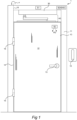
- FIG. 1 is a schematic front view of a swing door-based entrance system.
- the entrance system 1 comprises a swing door member 10 having a door leaf 12.
- the swing door member 10 is pivotally supported at a vertical edge 14 by hinges 16 for allowing opening of the swing door member 10 from a closed position to an open position, as well as for allowing closing of the swing door member 10 from the open position to the closed position.
- the swing door member 10 is hence supported by a door frame 11 for pivotal motion around a rotational axis 18 which is coincident with the hinges 16.
- the entrance system 1 comprises a motorized automatic door operator 30 capable of causing opening of the swing door member 10.
- a linkage (arm mechanism) 40 connects the automatic door operator 30 to the door leaf 12 of the swing door member 10.
- the door operator 30 may be arranged in conjunction with the door frame 11 and is typically a concealed overhead installation in or at the door frame 11 (hence, the linkage mechanism 40 and automatic door operator 30 are normally not as visible to the naked eye as appears to be the case in Figure 1 ).
- the automatic door operator 30 may be triggered by sensor equipment in the entrance system 1.
- the sensor equipment includes activation sensors for this purpose.
- a first activation sensor S1 is automatic in the sense that it is adapted to detect an approaching user/person from some distance, without requiring physical interaction by the user/person, and accordingly trigger the automatic door operator 30 to open the swing door member 10.
- the automatic activation sensor may typically be implemented as an IR sensor, an image sensor or a radar sensor.
- the sensor equipment in the entrance system 1 shown in Figure 1 further includes a second activation sensor 15 which is configured for manual actuation by a user/person wishing to pass through the entrance system 1, wherein the manual actuation triggers the automatic door operator 30 to open the swing door member 10.
- the manual activation sensor 15 may typically be implemented as a mechanical push button, such as an "elbow switch” actuator as can be seen in Figure 1 .
- the entrance system 1 will typically also allow the user/person to open or close the swing door member 10 by pulling or pushing a door handle 13 by manual force, i.e. without using the motorized automatic door operator 30.
- the automatic door operator 30 may provide automatic opening of the swing door 10 in various possible applications. Such applications include, for instance, facilitating a disabled person's access to his or her private home, providing access through entrance ports or internal doors at healthcare buildings, office premises, industries or retail stores, providing comfort access to hotel rooms, etc.
- Figure 5 illustrates the opening of the swing door member 10 in one embodiment of the entrance system 1 from a shut closed position 18 to a swung open position 19.
- the opening movement is indicated by an arrow 2.
- the door leaf angle ⁇ will span from about 0° to about 90°, or slightly more than 90°.
- the swung open position may be at a door leaf angle ⁇ different from about 90°, such as for instance about 180°.
- Figure 6 correspondingly illustrates the closing of the swing door member 10 of the entrance system 1 from the swung open position 19 to the shut closed position 18.
- the closing movement is indicated by an arrow 3.
- the door leaf angle ⁇ will span from about 90°, or slightly more than 90°, to about 0°.
- the swung open position is at a door leaf angle ⁇ different from about 90°, such as for instance about 180°
- the door leaf angle ⁇ will of course start spanning from such other door leaf angle ⁇ .
- the entrance system 1 further comprises a safety sensor S2.
- the safety sensor S2 is typically mounted to the door leaf 12 at an appropriate position on the surface of the door leaf 12. As can be seen in Figure 1 , such a position is often at an uppermost part of the door leaf 12.
- the purpose of the safety sensor S2 is to monitor a zone PD, or volume, at or near the door leaf 12 for presence or activity of a person or object. If a person or object is detected in the monitored zone, the automatic door operator 30 shall not be allowed to move the swing door member 10 in a direction in which the swing door member 10 may hit or jam that person or object. Accordingly, the automatic door operator 30 is configured to receive monitoring data from the safety sensor S2. If the monitoring data indicates presence or activity of a person or object in the monitored zone, the automatic door operator 30 is configured to refrain from driving a motor of the automatic door operator 30 to cause movement of the swing door member 10, and/or force the motor to stop an ongoing movement of the swing door member 10.
- the automatic door operator 30 is adapted for use in the entrance system 1 that, as already mentioned, comprises the swing door member 10 which is operable between the closed position 18, in which passage is prevented, and the open position 19, in which passage is admitted.
- the automatic door operator 30 comprises a motor 34, typically an electrical motor, being connected to a transmission 35.
- An output shaft 35a of the transmission 35 rotates upon activation of the motor 34 and is connected to the linkage 40.
- the linkage 40 translates the motion of the output shaft 35a into an opening motion of the door leaf 12 with respect to the door frame 11 (c.f. opening movement 2 in Figure 5 ).
- the automatic door operator 30 also comprises a control arrangement 20 including a controller 31 which is configured for performing different functions of the automatic door operator 30.
- a controller 31 which is configured for performing different functions of the automatic door operator 30.
- One or more of these functions relates to opening of the door leaf 12 with respect to the door frame 11.
- the controller 31 has a control output 31a connected to the motor 34 for controlling the actuation thereof.
- control arrangement 20 comprises a number n of sensor functions, including or consisting of the aforementioned first activation sensor S1, second activation sensor 15 and safety sensor S2.
- the sensor functions are operatively connected with the controller 31 to report detection results or measurement readings to the controller 31.
- a revolution counter 33 such as an encoder or other angular sensor, is provided at the motor 34 to monitor the revolution of a motor shaft of the motor 34.
- the revolution counter 33 is connected to an input 31b of the controller 31.
- the controller 31 is configured to use one or more readings of the revolution counter 33, typically a number of pulses generated as the motor shaft rotates, for determining a current angular position, e.g. door leaf angle ⁇ , of the door leaf 12 of the swing door member 10.
- the controller 31 may be implemented in any known controller technology, including but not limited to microcontroller, processor (e.g. PLC, CPU, DSP), FPGA, ASIC or any other suitable digital and/or analog circuitry capable of performing the intended functionality.
- the controller 31 may be implemented as a single unit or as a cluster of units in a cooperative configuration for providing the functionalities as described in this document.
- the controller 31 has an associated memory 32.
- the memory 32 may be implemented in any known memory technology, including but not limited to E(E)PROM, S(D)RAM or flash memory. In some embodiments, the memory 32 may be integrated with or internal to the controller 31. As seen at 32a, the memory 32 may store program instructions for execution by the controller 31, as well as temporary and permanent data used by the controller 31.
- the embodiment of the automatic door operator 30 shown in Figure 2 is intended for fire door usage and includes a forced close arrangement 36.
- the forced close arrangement 36 is adapted to provide mechanical energy via a transfer mechanism to the linkage 40, so as to cause forced closing of the door leaf 12 with respect to the door frame 11 in the event of a fire alarm.
- the forced close arrangement 36 comprises a helical compression spring.
- the compression spring is tensioned by the rotation of the output shaft 35a, as can be seen at 36a.
- the transfer mechanism which in the disclosed embodiment includes a pressure roller that acts on a cam curve being connected to the output shaft 35a.
- the forced close arrangement 36 may comprise a different kind of spring, and its transfer mechanism may comprise a different kind of mechanism.
- the controller 31 may receive an alarm signal AS via a communication interface 22 and generate a control signal 31c to the forced close arrangement 36, so as to cause release of the accumulated spring force.
- the swing door-based entrance system 1 has a hold open function, as was described in the Background section of this document. During the hold open period, the controller 31 keeps on actuating the electric motor 34 to prevent the swing door member 10 from closing. This facilitates passage through the entrance system 1.
- the automatic door operator 30 has a configured hold open period, such as 5 seconds, after triggering by the activation sensor 15 (or S1).
- the configured hold open period may be a default hold open period predefined already at manufacturing, or a hold open period subsequently defined by an installer or service person during configuration or service of the entrance system 1.
- the configured hold open period may be insufficiently long in some situations, and the user may thus extend the hold open period by keeping the manual activation sensor 15 actuated for as long as the user finds appropriate, in effect making a manual override of the configured hold open period.
- the effective hold open period will be extended to at least 10 seconds, and typically a few seconds more depending on configuration of the entrance system.
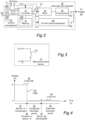
- the controller 31 of the automatic door operator 30 monitors the manual activation sensor 15 to detect a change in voltage of the output activation signal 15a from the sensor 15.
- an electric switch 15b (see Figure 3 ) will be switched from an open circuit state (essentially infinite resistance and therefore an output voltage essentially corresponding to a supply voltage, such a +5 V) to a closed circuit state (essentially zero resistance and therefore essentially zero output voltage).
- the controller 31 of the automatic door operator 30 is therefore configured to monitor the output voltage from the manual activation sensor 15.
- the output voltage level 50 will be high, e.g. at supply voltage level such as +5 V, since the electric switch 15b is in the open circuit state.
- the controller 31 is configured to detect a resulting edge 52 in the output voltage from the manual activation sensor 15 when the output voltage level changes at 52 from high (e.g. +5 V) to low (e.g. about 0 V). Accordingly, the automatic door operator 30 causes the swing door member 10 to open and remain open during the configured hold open period 43 by actuation of the motor 34.
- the controller 31 of the automatic door operator 30 moreover monitors the voltage level of the output activation signal 15a from the manual activation sensor 15 when the configured hold open period 43 lapses. As seen at 44 in Figure 4 , if the user keeps the manual activation sensor 15 actuated, the voltage level will remain at the low level 54 when the configured hold open period has lapsed. The controller 31 of the automatic door operator 30 is configured to interpret this as a manual override of the configured hold open period and thus keep on actuating the motor 34 to keep the swing door member 10 in the open position during an extended hold open period, which is seen at 45 in Figure 4 .
- the following problematic situation is recalled from the Background section of this document. If the emergency situation develops into an actual fire, then massive heat generation will occur.
- the massive heat may melt either the manual activation sensor 15, or the electrical wiring that connects the sensor 15 to the control arrangement 20 of the automatic door operator 30 .
- a short circuit may occur that causes the output activation signal 15a to go permanently low (see 54 in Figure 4 , about 0 V), spuriously indicating a permanently closed switch 15b.
- the automatic door operator 30 would then not only open the swing door member 10 in response to the edge 52 in the output voltage when the short circuit occurs, but also keep the swing door member 10 open for a long, undefined hold open period - because the short circuit keeps the output voltage level low. As a result, the automatic door operator 30 would fail to close the swing door member to entrap the fire when really needed.
- the controller 31 of the automatic door operator 30 has a normal operating mode and an emergency mode.
- the automatic door operator 30 has an emergency detection function which is configured for detecting an emergency situation.
- the emergency detection function may be implemented as or associated with a smoke detector SD, and/or an excessive heat detector EHD, that may be mounted at an appropriate position in the entrance system 1, as is exemplified in Figure 1 .
- the emergency detection function may be implemented as or associated with the communication interface 22, being capable of receiving an external alarm signal such as the aforementioned alarm signal AS (see Figure 2 ).
- the controller 31 Being in the normal operating mode, the controller 31 is responsive to the emergency detection function and configured for switching to the emergency mode.
- the controller 31 is responsive to the activation sensor 15 and configured for the following functionality.
- the controller 31 in response controls the motor 34 to generate torque for causing the swing door member 10 in the entrance system 1 to move from the closed position 18 to the open position 19, and to stay in the open position 19 during the configured hold open period 43.
- the controller 31 controls the motor 34 to generate torque for causing the swing door member 10 to remain in the open position 19 during the extended hold open period 45.
- the extended hold open period 45 typically lasts as least during the duration of the maintained actuation of the activation sensor 15, possibly a few seconds longer if the system is set up in that way.
- the controller 31 is responsive to the activation sensor 15 and configured for the following functionality.
- the controller 31 in response controls the motor 34 to generate torque for causing the swing door member 10 in the entrance system 1 to move from the closed position 18 to the open position 19, and to stay in the open position 19 during the configured hold open period 43.
- the controller 31 is configured in the emergency mode to ignore a spurious indication of a maintained actuation 44 of the activation sensor 15 and thereby prevent the door member 10 from remaining in the open position 19 during an extended hold open period 45.
- the safety sensor S2 is typically disabled in the emergency mode, to avoid spurious detection of smoke which may otherwise be mistaken for a person or object and thus prevent door opening or stop an ongoing opening of the door.
- the above functionality has been implemented as follows.
- the activation sensor 15 comprises the aforementioned switch 15b which is in an open circuit state when the manual activation sensor 15 is not actuated and switches from the open circuit state to a closed circuit state when the manual activation sensor 15 is actuated.
- the open circuit state causes the output activation signal 15a from the activation sensor 15 to have a first output voltage level 50
- the closed circuit state causes the output activation signal 15a from the activation sensor 15 to have a second output voltage level 54, different from the first output voltage level 50.
- the first output voltage level 50 essentially corresponds to a supply voltage
- the second output voltage level 54 essentially corresponds to zero voltage or ground.
- the controller 31 is responsive to the activation sensor 15 by being triggerable both by the edge 52 and by a level (or more specifically the low level 54) of the output activation signal 15a from the activation sensor 15.
- the controller 31 is responsive to the activation sensor 15 by being triggerable by the edge 52 but not by the level 54 of the output activation signal 15a from the activation sensor 15.
- the automatic door operator 30 can remain operative also in a situation of emergency, e.g. involving smoke or fire, and may in particular offer hold-open functionality to facilitate evacuation through the entrance system 1, at the same time preventing hazardous extended hold-open caused by a spurious constant low voltage level in the output activation signal 15a from the activation sensor 15, due to component melt-down and a resulting short circuit.
- Figure 7A illustrates the functionality of the method 100 when the automatic door operator 30 operates in normal operating mode 110.
- Figure 7B illustrates the functionality of the method 100 when the automatic door operator 30 operates in emergency mode 160, different from the normal operating mode 110.
- the method 100 involves a step 120 (in the normal operating mode 110) and 170 (in the emergency mode 160), respectively, of detecting actuation 42 of the activation sensor 15 by a person wishing to pass through the entrance system 1.
- the method 100 then involves a step 130 (in the normal operating mode 110) and 180 (in the emergency mode 160), respectively, of operating the automatic door operator 30 to cause movement of the swing door member 10 between the closed position 18 and the open position 19, and to keep the swing door member 10 in the open position 19 during a configured hold open period 43.
- the method 100 then involves detecting in a step 140 that the activation sensor 15 is maintained actuated 44 when the configured hold open period 43 has lapsed, and operating in a step 150 the automatic door operator 30 to keep the swing door member 10 in the open position 19 during an extended hold open period 45.
- the method 100 instead ignores a spurious indication of the activation sensor 15 being maintained actuated 44 when the configured hold open period 43 has lapsed, thereby preventing the swing door member 10 from remaining in the open position 19 during an extended hold open period 45
Landscapes
- Business, Economics & Management (AREA)
- Emergency Management (AREA)
- Power-Operated Mechanisms For Wings (AREA)
Claims (11)
- Automatischer Türantrieb (30) zur Verwendung in einem Eingangssystem (1), der ein Schwenktürelement (10) aufweist, das zwischen einer geschlossenen Position (18), die den Durchgang verhindert, und einer offenen Position (19), die den Durchgang zulässt, betätigt werden kann, wobei der automatische Türantrieb (30) aufweist:einen Elektromotor (34);einen Aktivierungssensor (15), der zur manuellen Betätigung durch eine Person ausgebildet ist, die das Eingangssystem passieren möchte; undeine Steuerung (31) mit einem normalen Betriebsmodus und einem Notfallmodus,wobei in dem normalen Betriebsmodus die Steuerung auf den Aktivierungssensor (15) anspricht und derart ausgebildet ist, dassdann, wenn der Aktivierungssensor (15) betätigt wird, der Motor (34) gesteuert wird, um ein Drehmoment zu erzeugen, um zu bewirken, dass sich das Türelement (10) in dem Eingangssystem (1) von der geschlossenen Position (18) in die offene Position (19) bewegt und während eines bestimmten Offenhaltezeitraums (43) in der offenen Position (19) bleibt, unddann, wenn der bestimmte Offenhaltezeitraum abgelaufen ist und der Aktivierungssensor (15) betätigt bleibt (44), der Motor (34) gesteuert wird, um ein Drehmoment zu erzeugen, um zu bewirken, dass das Türelement (10) während eines verlängerten Offenhaltezeitraums (45) in der offenen Position (19) bleibt;wobei im Notfallmodus die Steuerung auf den Aktivierungssensor (15) anspricht und derart ausgebildet ist, dasssie den Motor (34) steuert, wenn der Aktivierungssensor (15) betätigt wird, um ein Drehmoment zu erzeugen, das bewirkt, dass sich das Türelement (10) in dem Eingangssystem (1) von der geschlossenen Position (18) in die offene Position (19) bewegt, um während des bestimmten Offenhaltezeitraums (43) in der offenen Position (19) zu verbleiben, aber ein falsches Indiz einer aufrechterhaltenen Betätigung (44) des Aktivierungssensors (15) zu ignorieren und dadurch zu verhindern, dass das Türelement (10) während eines verlängerten Offenhaltezeitraums (45) in der offenen Position (19) verbleibt.
- Automatischer Türantrieb (30) nach Anspruch 1, wobei:im normalen Betriebsmodus die Steuerung (31) auf den Aktivierungssensor (15) anspricht, indem sie sowohl durch eine Flanke (52) als auch durch einen Pegel (54) eines Ausgangsaktivierungssignals (15a) von dem Aktivierungssensor (15) auslösbar ist; undin dem Notfallmodus die Steuerung (31) auf den Aktivierungssensor (15) reagiert, indem sie durch die Flanke (52), aber nicht durch den Pegel (54) des Ausgangsaktivierungssignals (15a) von dem Aktivierungssensor (15) auslösbar ist.
- Automatischer Türantrieb (30) nach Anspruch 2, wobei der Aktivierungssensor (15) einen Schalter (15b) aufweist, der sich in einem offenen Schaltkreiszustand befindet, wenn der manuelle Aktivierungssensor (15) nicht betätigt wird, und von dem offenen Schaltkreiszustand in einen geschlossenen Schaltkreiszustand umschaltet, wenn der manuelle Aktivierungssensor (15) betätigt wird, wobei der offene Schaltkreiszustand bewirkt, dass das Ausgangsaktivierungssignal (15a) von dem Aktivierungssensor (15) einen ersten Ausgangsspannungspegel (50) aufweist, und der geschlossene Schaltkreiszustand bewirkt, dass das Ausgangsaktivierungssignal (15a) von dem Aktivierungssensor (15) einen zweiten Ausgangsspannungspegel (54) aufweist, der sich von dem ersten Ausgangsspannungspegel (50) unterscheidet.
- Automatischer Türantrieb (30) nach Anspruch 3, wobei der erste Ausgangsspannungspegel (50) im Wesentlichen einer Versorgungsspannung entspricht und der zweite Ausgangsspannungspegel (54) im Wesentlichen einer Nullspannung oder Masse entspricht.
- Automatischer Türantrieb (30) nach einem der vorstehenden Ansprüche, wobei der verlängerte Offenhaltezeitraum (45) zumindest während der Dauer der aufrechterhaltenen Betätigung des Aktivierungssensors (15) andauert.
- Automatischer Türantrieb (30) nach einem der vorhergehenden Ansprüche, der ferner eine Funktion zur Erkennung von Notfällen aufweist, die derart ausgebildet ist, dass sie eine Notfallsituation erkennt.
- Automatischer Türantrieb (30) nach Anspruch 6, wobei die Funktion zur Erkennung von Notfallsituationen ausgewählt ist aus der Gruppe bestehend aus:einem Rauchdetektor (SD);einem Detektor für übermäßige Hitze (EHD); undeiner Kommunikations-Schnittstelle (22), die in der Lage ist, ein externes Alarmsignal (AS) zu empfangen.
- Automatischer Türantrieb (30) nach Anspruch 6 oder 7, wobei die Steuerung (31) im normalen Betriebsmodus auf die Funktion zur Erkennung des Notfalls anspricht und derart ausgebildet ist, dass sie in den Notfallmodus umschaltet.
- Eingangssystem (1), aufweisend:ein Schwenktürelement (10), das zwischen einer geschlossenen Position (18), die den Durchgang verhindert, und einer offenen Position (19), die den Durchgang zulässt, betätigbar ist; undeinen automatischen Türantrieb (30), wie in einem der Ansprüche 1 bis 8 definiert.
- Verfahren (100) zum Betreiben eines Eingangssystems (1), das ein Schwenktürelement (10) aufweist, das durch einen automatischen Türantrieb (30) zwischen einer geschlossenen Position (18), die den Durchgang verhindert, und einer offenen Position (19), die den Durchgang zulässt, betätigt werden kann, wobei das Verfahren Folgendes umfasst:Erkennen (120) der Betätigung (42) eines Aktivierungssensors (15) durch eine Person, die das Eingangssystem passieren möchte;Betätigen (130) des automatischen Türantriebs (30), um eine Bewegung des Schwenktürelements (10) zwischen der geschlossenen Position (18) und der offenen Position (19) zu bewirken und das Schwenktürelement (10) während eines bestimmten ausgebildeten Offenhaltzeitraums (43) in der offenen Position (19) zu halten;Erkennen (140), dass die Betätigung des Aktivierungssensors (15) aufrechterhalten wird (44), wenn der bestimmte Offenhaltzeitraum abgelaufen ist;Betreiben (150) des automatischen Türantriebs (30), um das Schwenktürelement (10) während einer verlängerten Offenhaltzeitraums (45) in der offenen Position (19) zu halten, es sei denn, der automatische Türantrieb (30) arbeitet in einem Notfallmodus (160), der sich von einem normalen Betriebsmodus (110) unterscheidet; undwenn der automatische Türantrieb (30) im Notfallmodus (160) arbeitet, Ignorieren eines falschen Indizes des Aktivierungssensors (15), der betätigt bleibt (44), wenn er bestimmte Offenhaltzeitraum (43) abgelaufen ist, wodurch verhindert wird, dass das Schwenktürelement (10) während eines verlängerten Offenhaltzeitraums (45) in der offenen Position (19) bleibt.
- Verfahren (100) nach Anspruch 10, wobei:im normalen Betriebsmodus die Betätigung (42) des Aktivierungssensors (15) durch die Person, die das Eingangssystem passieren möchte, zumindest als eine Flanke (52) eines Ausgangsaktivierungssignals (15a) des Aktivierungssensors (15) oder ein Pegel (54) des Ausgangsaktivierungssignals (15a) des Aktivierungssensors (15) erkannt wird (120); undim Notfallmodus die Betätigung (42) des Aktivierungssensors (15) durch die Person, die das Eingangssystem passieren möchte, als eine Flanke (52) des Ausgangsaktivierungssignals (15a) vom Aktivierungssensor (15), aber nicht als ein Pegel (54) des Ausgangsaktivierungssignals (15a) vom Aktivierungssensor (15) erkannt (170) wird.
Applications Claiming Priority (2)
| Application Number | Priority Date | Filing Date | Title |
|---|---|---|---|
| SE1930198 | 2019-06-17 | ||
| PCT/EP2020/065901 WO2020254142A1 (en) | 2019-06-17 | 2020-06-09 | Swing door-based entrance system with improved operability in emergency mode |
Publications (3)
| Publication Number | Publication Date |
|---|---|
| EP3983633A1 EP3983633A1 (de) | 2022-04-20 |
| EP3983633C0 EP3983633C0 (de) | 2023-06-07 |
| EP3983633B1 true EP3983633B1 (de) | 2023-06-07 |
Family
ID=71078529
Family Applications (1)
| Application Number | Title | Priority Date | Filing Date |
|---|---|---|---|
| EP20731858.5A Active EP3983633B1 (de) | 2019-06-17 | 2020-06-09 | Auf schwenktür basierendes eingangssystem mit verbesserter bedienbarkeit im notbetrieb |
Country Status (5)
| Country | Link |
|---|---|
| US (1) | US12054978B2 (de) |
| EP (1) | EP3983633B1 (de) |
| CN (1) | CN113994063B (de) |
| AU (1) | AU2020295632B2 (de) |
| WO (1) | WO2020254142A1 (de) |
Families Citing this family (8)
| Publication number | Priority date | Publication date | Assignee | Title |
|---|---|---|---|---|
| DE102019218172A1 (de) | 2019-11-25 | 2021-05-27 | Vitesco Technologies GmbH | Aktuator für eine Seitentür eines Kraftfahrzeuges mit Haltefunktion |
| TWI769855B (zh) | 2021-06-11 | 2022-07-01 | 一德金屬工業股份有限公司 | 利用即時無線供電的鎖具的解鎖方法 |
| TWI779908B (zh) * | 2021-10-27 | 2022-10-01 | 一德金屬工業股份有限公司 | 控制面板外露的門弓器 |
| TWI862927B (zh) * | 2022-05-20 | 2024-11-21 | 中華電信股份有限公司 | 減緩火勢之門窗控制系統、方法及電腦可讀媒介 |
| TWI815753B (zh) | 2022-12-19 | 2023-09-11 | 一德金屬工業股份有限公司 | 重型鎖匣 |
| TWI885339B (zh) | 2023-03-07 | 2025-06-01 | 一德金屬工業股份有限公司 | 密碼式鎖具的管控方法 |
| TWI854632B (zh) | 2023-05-04 | 2024-09-01 | 一德金屬工業股份有限公司 | 可緊急通報的門禁管制方法 |
| TWI891328B (zh) | 2024-04-18 | 2025-07-21 | 一德金屬工業股份有限公司 | 適用車輛的門禁管制方法 |
Family Cites Families (21)
| Publication number | Priority date | Publication date | Assignee | Title |
|---|---|---|---|---|
| US4727679A (en) | 1987-04-02 | 1988-03-01 | The Stanley Works | Swing-door operator system |
| CA2124403C (en) * | 1993-07-19 | 2001-12-18 | Mark A. Beran | Apparatus and method for selective alteration of operating parameters of a door |
| US5878530A (en) | 1994-10-18 | 1999-03-09 | Eccleston Mechanical | Remotely controllable automatic door operator permitting active and passive door operation |
| WO2000009966A2 (en) | 1998-08-12 | 2000-02-24 | The Cookson Company | Automatic door safety system with multiple safety modes |
| MX2016003121A (es) | 2013-09-09 | 2016-05-31 | Yale Security Inc | Metodo y aparato para aumentar la distancia de entradas y salidas digitales en un operador o cierre de puerta. |
| DE102015103756A1 (de) | 2015-03-13 | 2016-09-15 | Gu Automatic Gmbh | Automatiktür, wie beispielsweise eine Schiebetür, eine Drehtür oder dergleichen |
| DE102016202225A1 (de) * | 2016-02-15 | 2017-08-17 | Geze Gmbh | Bremsvorrichtung für einen beweglichen Türflügel und korrespondierender Türschließer |
| DE102016210777B3 (de) | 2016-06-16 | 2017-08-31 | Geze Gmbh | Türantrieb |
| EP3475512B1 (de) * | 2016-06-22 | 2021-12-01 | ASSA ABLOY Entrance Systems AB | Türbetätiger und verfahren zur einstellung eines türbetätigers |
| RU2754751C2 (ru) * | 2016-12-07 | 2021-09-07 | Асса Аблой Энтранс Системс АБ | Автоматический открыватель двери для распашной двери в сборе |
| CA3058288A1 (en) * | 2017-04-18 | 2018-10-25 | Assa Abloy Entrance Systems Ab | Control system for an automatic sliding door |
| WO2018197367A1 (en) * | 2017-04-24 | 2018-11-01 | Assa Abloy Entrance Systems Ab | Swing door operator |
| DE102017210434A1 (de) | 2017-06-21 | 2018-12-27 | Geze Gmbh | Elektrischer Türantrieb und Sicherheitstür |
| US10472873B2 (en) * | 2017-06-22 | 2019-11-12 | Riaz Ladha | Sensor based door closer with an intelligent control system |
| US11230872B2 (en) * | 2017-08-04 | 2022-01-25 | Assa Abloy Entrance Systems Ab | Door operator |
| KR102709376B1 (ko) * | 2017-09-01 | 2024-09-25 | 아사 알보이 엔트란스 시스템스 에이비 | 하나 이상의 가동 도어 부재를 갖는 출입구 시스템의 구성 |
| EP3785364A1 (de) * | 2018-04-23 | 2021-03-03 | ASSA ABLOY Entrance Systems AB | Antriebsanordnung für einen türbetätiger |
| US11536078B2 (en) * | 2018-06-15 | 2022-12-27 | Assa Abloy Entrance Systems Ab | Configuration of entrance systems having one or more movable door members |
| US11085212B2 (en) * | 2018-07-25 | 2021-08-10 | Ford Global Technologies, Llc | Selectively concealed door handle |
| EP3833838B1 (de) * | 2018-08-09 | 2024-08-21 | ASSA ABLOY Entrance Systems AB | Türbetätiger und verfahren zu dessen betrieb |
| CA3106295A1 (en) * | 2018-08-09 | 2020-02-13 | Assa Abloy Entrance Systems Ab | Parallel operation of door operators |
-
2020
- 2020-06-09 CN CN202080044135.1A patent/CN113994063B/zh active Active
- 2020-06-09 US US17/618,069 patent/US12054978B2/en active Active
- 2020-06-09 WO PCT/EP2020/065901 patent/WO2020254142A1/en not_active Ceased
- 2020-06-09 AU AU2020295632A patent/AU2020295632B2/en active Active
- 2020-06-09 EP EP20731858.5A patent/EP3983633B1/de active Active
Also Published As
| Publication number | Publication date |
|---|---|
| EP3983633C0 (de) | 2023-06-07 |
| US12054978B2 (en) | 2024-08-06 |
| EP3983633A1 (de) | 2022-04-20 |
| CN113994063A (zh) | 2022-01-28 |
| CN113994063B (zh) | 2023-09-05 |
| AU2020295632B2 (en) | 2025-10-16 |
| US20220307316A1 (en) | 2022-09-29 |
| AU2020295632A1 (en) | 2021-10-14 |
| WO2020254142A1 (en) | 2020-12-24 |
Similar Documents
| Publication | Publication Date | Title |
|---|---|---|
| EP3983633B1 (de) | Auf schwenktür basierendes eingangssystem mit verbesserter bedienbarkeit im notbetrieb | |
| EP3963166B1 (de) | Schwingtürbasiertes eingangssystem mit automatischer erkennung der verbindungsreduktionskurve | |
| CN112352086B (zh) | 具有一个或多个可移动门构件的进入系统的配置 | |
| AU2017371116B2 (en) | Automatic door operator for a swing door assembly | |
| US12227982B2 (en) | Testing system for swing door-based entrance system | |
| CN109098610A (zh) | 电动的门驱动装置和安全门 | |
| WO2020249454A1 (en) | Automatic entrance system with battery-driven evacuation mode | |
| US6611205B2 (en) | Gate operator safety system | |
| US12421782B2 (en) | Testing system for swing door-based entrance system | |
| EP3781772B1 (de) | Fingerquetschschutz für ein eingangssystem | |
| CA3041080C (en) | Automatic door operator for a swing door assembly | |
| WO2023280545A1 (en) | Door operator, swing door system and method for operating door operator | |
| JP3066026U (ja) | 電気錠装置 |
Legal Events
| Date | Code | Title | Description |
|---|---|---|---|
| STAA | Information on the status of an ep patent application or granted ep patent |
Free format text: STATUS: UNKNOWN |
|
| STAA | Information on the status of an ep patent application or granted ep patent |
Free format text: STATUS: THE INTERNATIONAL PUBLICATION HAS BEEN MADE |
|
| PUAI | Public reference made under article 153(3) epc to a published international application that has entered the european phase |
Free format text: ORIGINAL CODE: 0009012 |
|
| STAA | Information on the status of an ep patent application or granted ep patent |
Free format text: STATUS: REQUEST FOR EXAMINATION WAS MADE |
|
| 17P | Request for examination filed |
Effective date: 20220104 |
|
| AK | Designated contracting states |
Kind code of ref document: A1 Designated state(s): AL AT BE BG CH CY CZ DE DK EE ES FI FR GB GR HR HU IE IS IT LI LT LU LV MC MK MT NL NO PL PT RO RS SE SI SK SM TR |
|
| DAV | Request for validation of the european patent (deleted) | ||
| DAX | Request for extension of the european patent (deleted) | ||
| GRAP | Despatch of communication of intention to grant a patent |
Free format text: ORIGINAL CODE: EPIDOSNIGR1 |
|
| STAA | Information on the status of an ep patent application or granted ep patent |
Free format text: STATUS: GRANT OF PATENT IS INTENDED |
|
| INTG | Intention to grant announced |
Effective date: 20230126 |
|
| GRAS | Grant fee paid |
Free format text: ORIGINAL CODE: EPIDOSNIGR3 |
|
| GRAA | (expected) grant |
Free format text: ORIGINAL CODE: 0009210 |
|
| STAA | Information on the status of an ep patent application or granted ep patent |
Free format text: STATUS: THE PATENT HAS BEEN GRANTED |
|
| AK | Designated contracting states |
Kind code of ref document: B1 Designated state(s): AL AT BE BG CH CY CZ DE DK EE ES FI FR GB GR HR HU IE IS IT LI LT LU LV MC MK MT NL NO PL PT RO RS SE SI SK SM TR |
|
| REG | Reference to a national code |
Ref country code: GB Ref legal event code: FG4D |
|
| REG | Reference to a national code |
Ref country code: CH Ref legal event code: EP Ref country code: AT Ref legal event code: REF Ref document number: 1575584 Country of ref document: AT Kind code of ref document: T Effective date: 20230615 |
|
| REG | Reference to a national code |
Ref country code: DE Ref legal event code: R096 Ref document number: 602020012145 Country of ref document: DE |
|
| U01 | Request for unitary effect filed |
Effective date: 20230707 |
|
| U07 | Unitary effect registered |
Designated state(s): AT BE BG DE DK EE FI FR IT LT LU LV MT NL PT SE SI Effective date: 20230719 |
|
| U20 | Renewal fee for the european patent with unitary effect paid |
Year of fee payment: 4 Effective date: 20230808 |
|
| REG | Reference to a national code |
Ref country code: LT Ref legal event code: MG9D |
|
| PG25 | Lapsed in a contracting state [announced via postgrant information from national office to epo] |
Ref country code: NO Free format text: LAPSE BECAUSE OF FAILURE TO SUBMIT A TRANSLATION OF THE DESCRIPTION OR TO PAY THE FEE WITHIN THE PRESCRIBED TIME-LIMIT Effective date: 20230907 Ref country code: ES Free format text: LAPSE BECAUSE OF FAILURE TO SUBMIT A TRANSLATION OF THE DESCRIPTION OR TO PAY THE FEE WITHIN THE PRESCRIBED TIME-LIMIT Effective date: 20230607 |
|
| PG25 | Lapsed in a contracting state [announced via postgrant information from national office to epo] |
Ref country code: RS Free format text: LAPSE BECAUSE OF FAILURE TO SUBMIT A TRANSLATION OF THE DESCRIPTION OR TO PAY THE FEE WITHIN THE PRESCRIBED TIME-LIMIT Effective date: 20230607 Ref country code: HR Free format text: LAPSE BECAUSE OF FAILURE TO SUBMIT A TRANSLATION OF THE DESCRIPTION OR TO PAY THE FEE WITHIN THE PRESCRIBED TIME-LIMIT Effective date: 20230607 Ref country code: GR Free format text: LAPSE BECAUSE OF FAILURE TO SUBMIT A TRANSLATION OF THE DESCRIPTION OR TO PAY THE FEE WITHIN THE PRESCRIBED TIME-LIMIT Effective date: 20230908 |
|
| PG25 | Lapsed in a contracting state [announced via postgrant information from national office to epo] |
Ref country code: SK Free format text: LAPSE BECAUSE OF FAILURE TO SUBMIT A TRANSLATION OF THE DESCRIPTION OR TO PAY THE FEE WITHIN THE PRESCRIBED TIME-LIMIT Effective date: 20230607 |
|
| PG25 | Lapsed in a contracting state [announced via postgrant information from national office to epo] |
Ref country code: IS Free format text: LAPSE BECAUSE OF FAILURE TO SUBMIT A TRANSLATION OF THE DESCRIPTION OR TO PAY THE FEE WITHIN THE PRESCRIBED TIME-LIMIT Effective date: 20231007 |
|
| PG25 | Lapsed in a contracting state [announced via postgrant information from national office to epo] |
Ref country code: SM Free format text: LAPSE BECAUSE OF FAILURE TO SUBMIT A TRANSLATION OF THE DESCRIPTION OR TO PAY THE FEE WITHIN THE PRESCRIBED TIME-LIMIT Effective date: 20230607 Ref country code: SK Free format text: LAPSE BECAUSE OF FAILURE TO SUBMIT A TRANSLATION OF THE DESCRIPTION OR TO PAY THE FEE WITHIN THE PRESCRIBED TIME-LIMIT Effective date: 20230607 Ref country code: RO Free format text: LAPSE BECAUSE OF FAILURE TO SUBMIT A TRANSLATION OF THE DESCRIPTION OR TO PAY THE FEE WITHIN THE PRESCRIBED TIME-LIMIT Effective date: 20230607 Ref country code: IS Free format text: LAPSE BECAUSE OF FAILURE TO SUBMIT A TRANSLATION OF THE DESCRIPTION OR TO PAY THE FEE WITHIN THE PRESCRIBED TIME-LIMIT Effective date: 20231007 Ref country code: CZ Free format text: LAPSE BECAUSE OF FAILURE TO SUBMIT A TRANSLATION OF THE DESCRIPTION OR TO PAY THE FEE WITHIN THE PRESCRIBED TIME-LIMIT Effective date: 20230607 |
|
| REG | Reference to a national code |
Ref country code: CH Ref legal event code: PL |
|
| PG25 | Lapsed in a contracting state [announced via postgrant information from national office to epo] |
Ref country code: PL Free format text: LAPSE BECAUSE OF FAILURE TO SUBMIT A TRANSLATION OF THE DESCRIPTION OR TO PAY THE FEE WITHIN THE PRESCRIBED TIME-LIMIT Effective date: 20230607 |
|
| REG | Reference to a national code |
Ref country code: DE Ref legal event code: R097 Ref document number: 602020012145 Country of ref document: DE |
|
| PG25 | Lapsed in a contracting state [announced via postgrant information from national office to epo] |
Ref country code: MC Free format text: LAPSE BECAUSE OF FAILURE TO SUBMIT A TRANSLATION OF THE DESCRIPTION OR TO PAY THE FEE WITHIN THE PRESCRIBED TIME-LIMIT Effective date: 20230607 |
|
| REG | Reference to a national code |
Ref country code: IE Ref legal event code: MM4A |
|
| PG25 | Lapsed in a contracting state [announced via postgrant information from national office to epo] |
Ref country code: MC Free format text: LAPSE BECAUSE OF FAILURE TO SUBMIT A TRANSLATION OF THE DESCRIPTION OR TO PAY THE FEE WITHIN THE PRESCRIBED TIME-LIMIT Effective date: 20230607 |
|
| PLBE | No opposition filed within time limit |
Free format text: ORIGINAL CODE: 0009261 |
|
| STAA | Information on the status of an ep patent application or granted ep patent |
Free format text: STATUS: NO OPPOSITION FILED WITHIN TIME LIMIT |
|
| PG25 | Lapsed in a contracting state [announced via postgrant information from national office to epo] |
Ref country code: IE Free format text: LAPSE BECAUSE OF NON-PAYMENT OF DUE FEES Effective date: 20230609 |
|
| PG25 | Lapsed in a contracting state [announced via postgrant information from national office to epo] |
Ref country code: IE Free format text: LAPSE BECAUSE OF NON-PAYMENT OF DUE FEES Effective date: 20230609 Ref country code: CH Free format text: LAPSE BECAUSE OF NON-PAYMENT OF DUE FEES Effective date: 20230630 |
|
| 26N | No opposition filed |
Effective date: 20240308 |
|
| U20 | Renewal fee for the european patent with unitary effect paid |
Year of fee payment: 5 Effective date: 20240509 |
|
| U20 | Renewal fee for the european patent with unitary effect paid |
Year of fee payment: 6 Effective date: 20250522 |
|
| PGFP | Annual fee paid to national office [announced via postgrant information from national office to epo] |
Ref country code: GB Payment date: 20250508 Year of fee payment: 6 |
|
| PG25 | Lapsed in a contracting state [announced via postgrant information from national office to epo] |
Ref country code: CY Free format text: LAPSE BECAUSE OF FAILURE TO SUBMIT A TRANSLATION OF THE DESCRIPTION OR TO PAY THE FEE WITHIN THE PRESCRIBED TIME-LIMIT; INVALID AB INITIO Effective date: 20200609 |
|
| PG25 | Lapsed in a contracting state [announced via postgrant information from national office to epo] |
Ref country code: HU Free format text: LAPSE BECAUSE OF FAILURE TO SUBMIT A TRANSLATION OF THE DESCRIPTION OR TO PAY THE FEE WITHIN THE PRESCRIBED TIME-LIMIT; INVALID AB INITIO Effective date: 20200609 |
|
| PG25 | Lapsed in a contracting state [announced via postgrant information from national office to epo] |
Ref country code: TR Free format text: LAPSE BECAUSE OF FAILURE TO SUBMIT A TRANSLATION OF THE DESCRIPTION OR TO PAY THE FEE WITHIN THE PRESCRIBED TIME-LIMIT Effective date: 20230607 |