EP3984399A1 - Structures de semelle comprenant des plaques de polyoléfine et articles de chaussures formés à partir de celles-ci - Google Patents
Structures de semelle comprenant des plaques de polyoléfine et articles de chaussures formés à partir de celles-ci Download PDFInfo
- Publication number
- EP3984399A1 EP3984399A1 EP21212501.7A EP21212501A EP3984399A1 EP 3984399 A1 EP3984399 A1 EP 3984399A1 EP 21212501 A EP21212501 A EP 21212501A EP 3984399 A1 EP3984399 A1 EP 3984399A1
- Authority
- EP
- European Patent Office
- Prior art keywords
- percent
- sole structure
- footwear
- edge portion
- plate
- Prior art date
- Legal status (The legal status is an assumption and is not a legal conclusion. Google has not performed a legal analysis and makes no representation as to the accuracy of the status listed.)
- Granted
Links
Images


Classifications
-
- A—HUMAN NECESSITIES
- A43—FOOTWEAR
- A43B—CHARACTERISTIC FEATURES OF FOOTWEAR; PARTS OF FOOTWEAR
- A43B5/00—Footwear for sporting purposes
- A43B5/02—Football boots or shoes, i.e. for soccer, football or rugby
-
- A—HUMAN NECESSITIES
- A43—FOOTWEAR
- A43B—CHARACTERISTIC FEATURES OF FOOTWEAR; PARTS OF FOOTWEAR
- A43B13/00—Soles; Sole-and-heel integral units
- A43B13/02—Soles; Sole-and-heel integral units characterised by the material
- A43B13/04—Plastics, rubber or vulcanised fibre
-
- A—HUMAN NECESSITIES
- A43—FOOTWEAR
- A43B—CHARACTERISTIC FEATURES OF FOOTWEAR; PARTS OF FOOTWEAR
- A43B13/00—Soles; Sole-and-heel integral units
- A43B13/02—Soles; Sole-and-heel integral units characterised by the material
- A43B13/12—Soles with several layers of different materials
-
- A—HUMAN NECESSITIES
- A43—FOOTWEAR
- A43B—CHARACTERISTIC FEATURES OF FOOTWEAR; PARTS OF FOOTWEAR
- A43B13/00—Soles; Sole-and-heel integral units
- A43B13/02—Soles; Sole-and-heel integral units characterised by the material
- A43B13/12—Soles with several layers of different materials
- A43B13/122—Soles with several layers of different materials characterised by the outsole or external layer
-
- A—HUMAN NECESSITIES
- A43—FOOTWEAR
- A43B—CHARACTERISTIC FEATURES OF FOOTWEAR; PARTS OF FOOTWEAR
- A43B13/00—Soles; Sole-and-heel integral units
- A43B13/14—Soles; Sole-and-heel integral units characterised by the constructive form
- A43B13/141—Soles; Sole-and-heel integral units characterised by the constructive form with a part of the sole being flexible, e.g. permitting articulation or torsion
-
- A—HUMAN NECESSITIES
- A43—FOOTWEAR
- A43B—CHARACTERISTIC FEATURES OF FOOTWEAR; PARTS OF FOOTWEAR
- A43B13/00—Soles; Sole-and-heel integral units
- A43B13/14—Soles; Sole-and-heel integral units characterised by the constructive form
- A43B13/18—Resilient soles
- A43B13/187—Resiliency achieved by the features of the material, e.g. foam, non liquid materials
-
- A—HUMAN NECESSITIES
- A43—FOOTWEAR
- A43B—CHARACTERISTIC FEATURES OF FOOTWEAR; PARTS OF FOOTWEAR
- A43B3/00—Footwear characterised by the shape or the use
- A43B3/0036—Footwear characterised by the shape or the use characterised by a special shape or design
- A43B3/0078—Footwear characterised by the shape or the use characterised by a special shape or design provided with logos, letters, signatures or the like decoration
-
- B—PERFORMING OPERATIONS; TRANSPORTING
- B29—WORKING OF PLASTICS; WORKING OF SUBSTANCES IN A PLASTIC STATE IN GENERAL
- B29D—PRODUCING PARTICULAR ARTICLES FROM PLASTICS OR FROM SUBSTANCES IN A PLASTIC STATE
- B29D35/00—Producing footwear
- B29D35/06—Producing footwear having soles or heels formed and joined on to preformed uppers using a moulding technique, e.g. by injection moulding, pressing and vulcanising
- B29D35/061—Producing footwear having soles or heels formed and joined on to preformed uppers using a moulding technique, e.g. by injection moulding, pressing and vulcanising by injection moulding
- B29D35/062—Producing footwear having soles or heels formed and joined on to preformed uppers using a moulding technique, e.g. by injection moulding, pressing and vulcanising by injection moulding using means to bond the moulding material to the preformed uppers
-
- B—PERFORMING OPERATIONS; TRANSPORTING
- B29—WORKING OF PLASTICS; WORKING OF SUBSTANCES IN A PLASTIC STATE IN GENERAL
- B29D—PRODUCING PARTICULAR ARTICLES FROM PLASTICS OR FROM SUBSTANCES IN A PLASTIC STATE
- B29D35/00—Producing footwear
- B29D35/06—Producing footwear having soles or heels formed and joined on to preformed uppers using a moulding technique, e.g. by injection moulding, pressing and vulcanising
- B29D35/065—Producing footwear having soles or heels formed and joined on to preformed uppers using a moulding technique, e.g. by injection moulding, pressing and vulcanising by compression moulding, vulcanising or the like
- B29D35/067—Producing footwear having soles or heels formed and joined on to preformed uppers using a moulding technique, e.g. by injection moulding, pressing and vulcanising by compression moulding, vulcanising or the like using means to bond the moulding material to the preformed uppers
-
- B—PERFORMING OPERATIONS; TRANSPORTING
- B29—WORKING OF PLASTICS; WORKING OF SUBSTANCES IN A PLASTIC STATE IN GENERAL
- B29D—PRODUCING PARTICULAR ARTICLES FROM PLASTICS OR FROM SUBSTANCES IN A PLASTIC STATE
- B29D35/00—Producing footwear
- B29D35/06—Producing footwear having soles or heels formed and joined on to preformed uppers using a moulding technique, e.g. by injection moulding, pressing and vulcanising
- B29D35/08—Producing footwear having soles or heels formed and joined on to preformed uppers using a moulding technique, e.g. by injection moulding, pressing and vulcanising having multilayered parts
-
- B—PERFORMING OPERATIONS; TRANSPORTING
- B29—WORKING OF PLASTICS; WORKING OF SUBSTANCES IN A PLASTIC STATE IN GENERAL
- B29D—PRODUCING PARTICULAR ARTICLES FROM PLASTICS OR FROM SUBSTANCES IN A PLASTIC STATE
- B29D35/00—Producing footwear
- B29D35/12—Producing parts thereof, e.g. soles, heels, uppers, by a moulding technique
- B29D35/14—Multilayered parts
- B29D35/142—Soles
-
- B—PERFORMING OPERATIONS; TRANSPORTING
- B32—LAYERED PRODUCTS
- B32B—LAYERED PRODUCTS, i.e. PRODUCTS BUILT-UP OF STRATA OF FLAT OR NON-FLAT, e.g. CELLULAR OR HONEYCOMB, FORM
- B32B27/00—Layered products comprising a layer of synthetic resin
- B32B27/32—Layered products comprising a layer of synthetic resin comprising polyolefins
- B32B27/327—Layered products comprising a layer of synthetic resin comprising polyolefins comprising polyolefins obtained by a metallocene or single-site catalyst
-
- B—PERFORMING OPERATIONS; TRANSPORTING
- B32—LAYERED PRODUCTS
- B32B—LAYERED PRODUCTS, i.e. PRODUCTS BUILT-UP OF STRATA OF FLAT OR NON-FLAT, e.g. CELLULAR OR HONEYCOMB, FORM
- B32B3/00—Layered products comprising a layer with external or internal discontinuities or unevennesses, or a layer of non-planar shape; Layered products comprising a layer having particular features of form
- B32B3/02—Layered products comprising a layer with external or internal discontinuities or unevennesses, or a layer of non-planar shape; Layered products comprising a layer having particular features of form characterised by features of form at particular places, e.g. in edge regions
- B32B3/06—Layered products comprising a layer with external or internal discontinuities or unevennesses, or a layer of non-planar shape; Layered products comprising a layer having particular features of form characterised by features of form at particular places, e.g. in edge regions for securing layers together; for attaching the product to another member, e.g. to a support, or to another product, e.g. groove/tongue, interlocking
-
- B—PERFORMING OPERATIONS; TRANSPORTING
- B32—LAYERED PRODUCTS
- B32B—LAYERED PRODUCTS, i.e. PRODUCTS BUILT-UP OF STRATA OF FLAT OR NON-FLAT, e.g. CELLULAR OR HONEYCOMB, FORM
- B32B3/00—Layered products comprising a layer with external or internal discontinuities or unevennesses, or a layer of non-planar shape; Layered products comprising a layer having particular features of form
- B32B3/02—Layered products comprising a layer with external or internal discontinuities or unevennesses, or a layer of non-planar shape; Layered products comprising a layer having particular features of form characterised by features of form at particular places, e.g. in edge regions
- B32B3/08—Layered products comprising a layer with external or internal discontinuities or unevennesses, or a layer of non-planar shape; Layered products comprising a layer having particular features of form characterised by features of form at particular places, e.g. in edge regions characterised by added members at particular parts
-
- B—PERFORMING OPERATIONS; TRANSPORTING
- B32—LAYERED PRODUCTS
- B32B—LAYERED PRODUCTS, i.e. PRODUCTS BUILT-UP OF STRATA OF FLAT OR NON-FLAT, e.g. CELLULAR OR HONEYCOMB, FORM
- B32B3/00—Layered products comprising a layer with external or internal discontinuities or unevennesses, or a layer of non-planar shape; Layered products comprising a layer having particular features of form
- B32B3/26—Layered products comprising a layer with external or internal discontinuities or unevennesses, or a layer of non-planar shape; Layered products comprising a layer having particular features of form characterised by a particular shape of the outline of the cross-section of a continuous layer; characterised by a layer with cavities or internal voids ; characterised by an apertured layer
- B32B3/266—Layered products comprising a layer with external or internal discontinuities or unevennesses, or a layer of non-planar shape; Layered products comprising a layer having particular features of form characterised by a particular shape of the outline of the cross-section of a continuous layer; characterised by a layer with cavities or internal voids ; characterised by an apertured layer characterised by an apertured layer, the apertures going through the whole thickness of the layer, e.g. expanded metal, perforated layer, slit layer regular cells B32B3/12
-
- B—PERFORMING OPERATIONS; TRANSPORTING
- B32—LAYERED PRODUCTS
- B32B—LAYERED PRODUCTS, i.e. PRODUCTS BUILT-UP OF STRATA OF FLAT OR NON-FLAT, e.g. CELLULAR OR HONEYCOMB, FORM
- B32B3/00—Layered products comprising a layer with external or internal discontinuities or unevennesses, or a layer of non-planar shape; Layered products comprising a layer having particular features of form
- B32B3/26—Layered products comprising a layer with external or internal discontinuities or unevennesses, or a layer of non-planar shape; Layered products comprising a layer having particular features of form characterised by a particular shape of the outline of the cross-section of a continuous layer; characterised by a layer with cavities or internal voids ; characterised by an apertured layer
- B32B3/30—Layered products comprising a layer with external or internal discontinuities or unevennesses, or a layer of non-planar shape; Layered products comprising a layer having particular features of form characterised by a particular shape of the outline of the cross-section of a continuous layer; characterised by a layer with cavities or internal voids ; characterised by an apertured layer characterised by a layer formed with recesses or projections, e.g. hollows, grooves, protuberances, ribs
-
- B—PERFORMING OPERATIONS; TRANSPORTING
- B32—LAYERED PRODUCTS
- B32B—LAYERED PRODUCTS, i.e. PRODUCTS BUILT-UP OF STRATA OF FLAT OR NON-FLAT, e.g. CELLULAR OR HONEYCOMB, FORM
- B32B7/00—Layered products characterised by the relation between layers; Layered products characterised by the relative orientation of features between layers, or by the relative values of a measurable parameter between layers, i.e. products comprising layers having different physical, chemical or physicochemical properties; Layered products characterised by the interconnection of layers
- B32B7/02—Physical, chemical or physicochemical properties
- B32B7/022—Mechanical properties
-
- C—CHEMISTRY; METALLURGY
- C08—ORGANIC MACROMOLECULAR COMPOUNDS; THEIR PREPARATION OR CHEMICAL WORKING-UP; COMPOSITIONS BASED THEREON
- C08L—COMPOSITIONS OF MACROMOLECULAR COMPOUNDS
- C08L23/00—Compositions of homopolymers or copolymers of unsaturated aliphatic hydrocarbons having only one carbon-to-carbon double bond; Compositions of derivatives of such polymers
- C08L23/02—Compositions of homopolymers or copolymers of unsaturated aliphatic hydrocarbons having only one carbon-to-carbon double bond; Compositions of derivatives of such polymers not modified by chemical after-treatment
- C08L23/10—Homopolymers or copolymers of propene
- C08L23/12—Polypropene
-
- C—CHEMISTRY; METALLURGY
- C08—ORGANIC MACROMOLECULAR COMPOUNDS; THEIR PREPARATION OR CHEMICAL WORKING-UP; COMPOSITIONS BASED THEREON
- C08L—COMPOSITIONS OF MACROMOLECULAR COMPOUNDS
- C08L23/00—Compositions of homopolymers or copolymers of unsaturated aliphatic hydrocarbons having only one carbon-to-carbon double bond; Compositions of derivatives of such polymers
- C08L23/02—Compositions of homopolymers or copolymers of unsaturated aliphatic hydrocarbons having only one carbon-to-carbon double bond; Compositions of derivatives of such polymers not modified by chemical after-treatment
- C08L23/10—Homopolymers or copolymers of propene
- C08L23/14—Copolymers of propene
- C08L23/142—Copolymers of propene at least partially crystalline copolymers of propene with other olefins
-
- A—HUMAN NECESSITIES
- A43—FOOTWEAR
- A43B—CHARACTERISTIC FEATURES OF FOOTWEAR; PARTS OF FOOTWEAR
- A43B13/00—Soles; Sole-and-heel integral units
- A43B13/14—Soles; Sole-and-heel integral units characterised by the constructive form
- A43B13/22—Soles made slip-preventing or wear-resisting, e.g. by impregnation or spreading a wear-resisting layer
-
- A—HUMAN NECESSITIES
- A43—FOOTWEAR
- A43B—CHARACTERISTIC FEATURES OF FOOTWEAR; PARTS OF FOOTWEAR
- A43B9/00—Footwear characterised by the assembling of the individual parts
-
- A—HUMAN NECESSITIES
- A43—FOOTWEAR
- A43B—CHARACTERISTIC FEATURES OF FOOTWEAR; PARTS OF FOOTWEAR
- A43B9/00—Footwear characterised by the assembling of the individual parts
- A43B9/12—Stuck or cemented footwear
-
- A—HUMAN NECESSITIES
- A43—FOOTWEAR
- A43B—CHARACTERISTIC FEATURES OF FOOTWEAR; PARTS OF FOOTWEAR
- A43B9/00—Footwear characterised by the assembling of the individual parts
- A43B9/16—Footwear with soles moulded on to uppers or welded on to uppers without adhesive
-
- B—PERFORMING OPERATIONS; TRANSPORTING
- B29—WORKING OF PLASTICS; WORKING OF SUBSTANCES IN A PLASTIC STATE IN GENERAL
- B29D—PRODUCING PARTICULAR ARTICLES FROM PLASTICS OR FROM SUBSTANCES IN A PLASTIC STATE
- B29D35/00—Producing footwear
- B29D35/12—Producing parts thereof, e.g. soles, heels, uppers, by a moulding technique
- B29D35/122—Soles
-
- B—PERFORMING OPERATIONS; TRANSPORTING
- B32—LAYERED PRODUCTS
- B32B—LAYERED PRODUCTS, i.e. PRODUCTS BUILT-UP OF STRATA OF FLAT OR NON-FLAT, e.g. CELLULAR OR HONEYCOMB, FORM
- B32B2274/00—Thermoplastic elastomer material
-
- B—PERFORMING OPERATIONS; TRANSPORTING
- B32—LAYERED PRODUCTS
- B32B—LAYERED PRODUCTS, i.e. PRODUCTS BUILT-UP OF STRATA OF FLAT OR NON-FLAT, e.g. CELLULAR OR HONEYCOMB, FORM
- B32B2307/00—Properties of the layers or laminate
- B32B2307/40—Properties of the layers or laminate having particular optical properties
- B32B2307/402—Coloured
- B32B2307/4023—Coloured on the layer surface, e.g. ink
-
- B—PERFORMING OPERATIONS; TRANSPORTING
- B32—LAYERED PRODUCTS
- B32B—LAYERED PRODUCTS, i.e. PRODUCTS BUILT-UP OF STRATA OF FLAT OR NON-FLAT, e.g. CELLULAR OR HONEYCOMB, FORM
- B32B2307/00—Properties of the layers or laminate
- B32B2307/50—Properties of the layers or laminate having particular mechanical properties
- B32B2307/546—Flexural strength; Flexion stiffness
-
- B—PERFORMING OPERATIONS; TRANSPORTING
- B32—LAYERED PRODUCTS
- B32B—LAYERED PRODUCTS, i.e. PRODUCTS BUILT-UP OF STRATA OF FLAT OR NON-FLAT, e.g. CELLULAR OR HONEYCOMB, FORM
- B32B2323/00—Polyalkenes
- B32B2323/10—Polypropylene
-
- B—PERFORMING OPERATIONS; TRANSPORTING
- B32—LAYERED PRODUCTS
- B32B—LAYERED PRODUCTS, i.e. PRODUCTS BUILT-UP OF STRATA OF FLAT OR NON-FLAT, e.g. CELLULAR OR HONEYCOMB, FORM
- B32B2437/00—Clothing
- B32B2437/02—Gloves, shoes
-
- B—PERFORMING OPERATIONS; TRANSPORTING
- B32—LAYERED PRODUCTS
- B32B—LAYERED PRODUCTS, i.e. PRODUCTS BUILT-UP OF STRATA OF FLAT OR NON-FLAT, e.g. CELLULAR OR HONEYCOMB, FORM
- B32B3/00—Layered products comprising a layer with external or internal discontinuities or unevennesses, or a layer of non-planar shape; Layered products comprising a layer having particular features of form
- B32B3/26—Layered products comprising a layer with external or internal discontinuities or unevennesses, or a layer of non-planar shape; Layered products comprising a layer having particular features of form characterised by a particular shape of the outline of the cross-section of a continuous layer; characterised by a layer with cavities or internal voids ; characterised by an apertured layer
-
- B—PERFORMING OPERATIONS; TRANSPORTING
- B32—LAYERED PRODUCTS
- B32B—LAYERED PRODUCTS, i.e. PRODUCTS BUILT-UP OF STRATA OF FLAT OR NON-FLAT, e.g. CELLULAR OR HONEYCOMB, FORM
- B32B5/00—Layered products characterised by the non- homogeneity or physical structure, i.e. comprising a fibrous, filamentary, particulate or foam layer; Layered products characterised by having a layer differing constitutionally or physically in different parts
- B32B5/14—Layered products characterised by the non- homogeneity or physical structure, i.e. comprising a fibrous, filamentary, particulate or foam layer; Layered products characterised by having a layer differing constitutionally or physically in different parts characterised by a layer differing constitutionally or physically in different parts, e.g. denser near its faces
- B32B5/142—Variation across the area of the layer
-
- B—PERFORMING OPERATIONS; TRANSPORTING
- B32—LAYERED PRODUCTS
- B32B—LAYERED PRODUCTS, i.e. PRODUCTS BUILT-UP OF STRATA OF FLAT OR NON-FLAT, e.g. CELLULAR OR HONEYCOMB, FORM
- B32B7/00—Layered products characterised by the relation between layers; Layered products characterised by the relative orientation of features between layers, or by the relative values of a measurable parameter between layers, i.e. products comprising layers having different physical, chemical or physicochemical properties; Layered products characterised by the interconnection of layers
- B32B7/04—Interconnection of layers
- B32B7/08—Interconnection of layers by mechanical means
-
- C—CHEMISTRY; METALLURGY
- C08—ORGANIC MACROMOLECULAR COMPOUNDS; THEIR PREPARATION OR CHEMICAL WORKING-UP; COMPOSITIONS BASED THEREON
- C08F—MACROMOLECULAR COMPOUNDS OBTAINED BY REACTIONS ONLY INVOLVING CARBON-TO-CARBON UNSATURATED BONDS
- C08F210/00—Copolymers of unsaturated aliphatic hydrocarbons having only one carbon-to-carbon double bond
- C08F210/04—Monomers containing three or four carbon atoms
- C08F210/06—Propene
-
- C—CHEMISTRY; METALLURGY
- C08—ORGANIC MACROMOLECULAR COMPOUNDS; THEIR PREPARATION OR CHEMICAL WORKING-UP; COMPOSITIONS BASED THEREON
- C08F—MACROMOLECULAR COMPOUNDS OBTAINED BY REACTIONS ONLY INVOLVING CARBON-TO-CARBON UNSATURATED BONDS
- C08F2500/00—Characteristics or properties of obtained polyolefins; Use thereof
- C08F2500/27—Amount of comonomer in wt% or mol%
-
- C—CHEMISTRY; METALLURGY
- C08—ORGANIC MACROMOLECULAR COMPOUNDS; THEIR PREPARATION OR CHEMICAL WORKING-UP; COMPOSITIONS BASED THEREON
- C08F—MACROMOLECULAR COMPOUNDS OBTAINED BY REACTIONS ONLY INVOLVING CARBON-TO-CARBON UNSATURATED BONDS
- C08F2500/00—Characteristics or properties of obtained polyolefins; Use thereof
- C08F2500/30—Flexural modulus; Elasticity modulus
-
- C—CHEMISTRY; METALLURGY
- C08—ORGANIC MACROMOLECULAR COMPOUNDS; THEIR PREPARATION OR CHEMICAL WORKING-UP; COMPOSITIONS BASED THEREON
- C08F—MACROMOLECULAR COMPOUNDS OBTAINED BY REACTIONS ONLY INVOLVING CARBON-TO-CARBON UNSATURATED BONDS
- C08F2800/00—Copolymer characterised by the proportions of the comonomers expressed
- C08F2800/20—Copolymer characterised by the proportions of the comonomers expressed as weight or mass percentages
-
- Y—GENERAL TAGGING OF NEW TECHNOLOGICAL DEVELOPMENTS; GENERAL TAGGING OF CROSS-SECTIONAL TECHNOLOGIES SPANNING OVER SEVERAL SECTIONS OF THE IPC; TECHNICAL SUBJECTS COVERED BY FORMER USPC CROSS-REFERENCE ART COLLECTIONS [XRACs] AND DIGESTS
- Y10—TECHNICAL SUBJECTS COVERED BY FORMER USPC
- Y10T—TECHNICAL SUBJECTS COVERED BY FORMER US CLASSIFICATION
- Y10T428/00—Stock material or miscellaneous articles
- Y10T428/24—Structurally defined web or sheet [e.g., overall dimension, etc.]
- Y10T428/24479—Structurally defined web or sheet [e.g., overall dimension, etc.] including variation in thickness
- Y10T428/24488—Differential nonuniformity at margin
-
- Y—GENERAL TAGGING OF NEW TECHNOLOGICAL DEVELOPMENTS; GENERAL TAGGING OF CROSS-SECTIONAL TECHNOLOGIES SPANNING OVER SEVERAL SECTIONS OF THE IPC; TECHNICAL SUBJECTS COVERED BY FORMER USPC CROSS-REFERENCE ART COLLECTIONS [XRACs] AND DIGESTS
- Y10—TECHNICAL SUBJECTS COVERED BY FORMER USPC
- Y10T—TECHNICAL SUBJECTS COVERED BY FORMER US CLASSIFICATION
- Y10T428/00—Stock material or miscellaneous articles
- Y10T428/24—Structurally defined web or sheet [e.g., overall dimension, etc.]
- Y10T428/24479—Structurally defined web or sheet [e.g., overall dimension, etc.] including variation in thickness
- Y10T428/24612—Composite web or sheet
-
- Y—GENERAL TAGGING OF NEW TECHNOLOGICAL DEVELOPMENTS; GENERAL TAGGING OF CROSS-SECTIONAL TECHNOLOGIES SPANNING OVER SEVERAL SECTIONS OF THE IPC; TECHNICAL SUBJECTS COVERED BY FORMER USPC CROSS-REFERENCE ART COLLECTIONS [XRACs] AND DIGESTS
- Y10—TECHNICAL SUBJECTS COVERED BY FORMER USPC
- Y10T—TECHNICAL SUBJECTS COVERED BY FORMER US CLASSIFICATION
- Y10T428/00—Stock material or miscellaneous articles
- Y10T428/24—Structurally defined web or sheet [e.g., overall dimension, etc.]
- Y10T428/24777—Edge feature
Definitions
- this disclosure provides sole structures including a plate containing a polyolefin resin composition, and an edge portion attached to an outer perimeter of the plate.
- Plates having the polyolefin resin compositions can have improved mechanical properties making them particularly suitable for use in components for footwear and sporting equipment. Specifically, these resin compositions are both resistant to stress whitening or cracking when flexed under cold conditions and resistant to abrasion to the levels needed for use in footwear and sporting equipment. However, the connection between the plate and the upper at the biteline is not always as durable as desired.
- the sole structures include the plate, the edge portion, and a textile on one or more surfaces of the plate. The textile can improve the bonding of other components (e.g. an upper or a chassis) to the plate, the edge portion, or both. The textile can also be used for decorative purposes.
- the edge portion can be extended so that it overlaps and wraps about at least a portion of the upper. When affixed to the upper, the extended edge portion can provide a more durable bond between the sole structure and the upper.
- the extended edge portion can be disposed around substantially the entire outer periphery of the article of footwear, or only in target areas. For example, the extended edge portion may extend about the forefoot portion, the midfoot portion, the heel portion or a combination thereof.
- the extended edge portion may provide additional properties, such as abrasion resistance, water resistance, or a combination thereof.
- the extended edge portion may have a decorative appearance, such as a colored or printed decorative element. In some aspects, the extended edge portion may have a textured surface.
- this disclosure provides a sole structure for an article of footwear, the sole structure having a plate containing a first polyolefin resin, the plate having a first side and a second side, and a perimeter, wherein the first side is configured to be ground-facing when the plate is a component of an article of footwear; and an edge portion comprising a second resin that is different from the first polyolefin resin, the edge portion disposed on at least a portion of the perimeter.
- the edge portion is more flexible than the plate.
- a textile is disposed on one or both of the first side and the second side.
- the sole structure further includes a chassis configured to be on the first side of the plate.
- a sole structure for an article of footwear comprising: a plate comprising a first polyolefin resin, the plate having a first side and a second side and a perimeter, wherein the first side is configured to be ground-facing when the plate is a component of an article of footwear; and an edge portion comprising a second resin that is different from the first polyolefin resin, the edge portion disposed on at least a portion of the perimeter.
- Aspect 2 The sole structure according to any one of Aspect 1 to Aspect 127, wherein the edge portion is more flexible than the plate.
- Aspect 5 The sole structure according to any one of Aspect 1 to Aspect 127, wherein the edge portion is separately formed, and operably coupled with the plate.
- Aspect 6 The sole structure according to any one of Aspect 1 to Aspect 127, wherein the edge portion is disposed about substantially the entire perimeter of the plate.
- Aspect 9 The sole structure according to any one of Aspect 1 to Aspect 127, wherein the edge portion is mechanically bonded to the plate.
- Aspect 13 The sole structure according to any one of Aspect 1 to Aspect 127, wherein the edge portion has a Durometer hardness that is at least 10 percent, or at least 15 percent or at least 20 percent or at least 25 percent, or at least 30 percent or at least 35 percent lower than a Durometer hardness of the plate.
- Aspect 24 The sole structure according to any one of Aspect 1 to Aspect 127, wherein the second resin comprises a resin composition that is the same as that of first polyolefin resin, except comprising a greater amount of polymeric resin modifier.
- Aspect 31 The sole structure according to any one of Aspect 1-Aspect 127, wherein the second resin comprises a block copolymer comprising a polystyrene block.
- Aspect 32 The sole structure according to any one of Aspect 1 to Aspect 127, wherein the block copolymer comprises a copolymer of styrene and one or both of ethylene and butylene.
- a sole structure for an article of footwear comprising: a plate comprising a first polyolefin resin, the plate having a first side and a second side and a perimeter, wherein the first side is configured to be ground-facing when the plate is a component of an article of footwear; an edge portion comprising a second resin that is different than the first polyolefin resin, the edge portion disposed on at least a portion of the perimeter; and a chassis, wherein the chassis is disposed on the first side of the plate.
- Aspect 45 The sole structure according to any one of Aspect 1 to Aspect 127, wherein the second resin comprises a polymeric component that is substantially similar to the polymeric component of the first polyolefin resin, except the polymeric component of the second resin comprises a greater concentration of the resin modifier than the polymeric component of the first polyolefin resin.
- Aspect 56 The sole structure according to any one of Aspect 1 to Aspect 127, wherein the third resin comprises about 20 percent, about 10 percent, or less of polypropylene.
- Aspect 62 The sole structure according to any one of Aspect 1 to Aspect 127, wherein a length of the plate is configured to extend through a midfoot region to a heel region of the article of footwear when the sole structure is the component of the article of footwear.
- Aspect 71 The sole structure according to any one of Aspect 1 to Aspect 127, wherein the one or more traction elements comprise one or more of the first polyolefin resin, the second resin, and the third resin.
- Aspect 73 The sole structure according to any one of Aspect 1 to Aspect 127, wherein the fourth resin comprises a resin composition according to any one of Aspect 195 to Aspect 260.
- Aspect 74 The sole structure according to any one of Aspect 1 to Aspect 127, wherein the fourth resin comprises an elastomeric material, optionally an olefin elastomer.
- Aspect 76 The sole structure according to any one of Aspect 1 to Aspect 127, wherein the fourth resin comprises about 20 percent, about 10 percent, or less of a polyolefin.
- Aspect 78 The sole structure according to any one of Aspect 1 to Aspect 127, wherein the fourth resin comprises an ethylene-propylene rubber (EPDM) dispersed in a polypropylene.
- EPDM ethylene-propylene rubber
- Aspect 79 The sole structure according to any one of Aspect 1 to Aspect 127, wherein the fourth resin comprises a block copolymer comprising a polystyrene block.
- Aspect 80 The sole structure according to any one of Aspect 1 to Aspect 127, wherein the block copolymer comprises a copolymer of styrene and one or both of ethylene and butylene.
- Aspect 82 The sole structure according to any one of Aspect 1 to Aspect 127, wherein the textile overlaps with at least a portion of the edge portion.
- Aspect 83 The sole structure according to any one of Aspect 1 to Aspect 127, wherein the textile does not overlap the edge portion.
- Aspect 84 The sole structure according to any one of Aspect 1 to Aspect 127, wherein the textile is disposed on the first side of the plate, and wherein a bond strength of the first side to the chassis is greater than a bond strength of the otherwise same plate to the otherwise same chassis using the otherwise same bonding procedure except without the textile.
- Aspect 85 The sole structure according to any one of Aspect 1 to Aspect 127, wherein the textile is on the first side of the plate, and wherein the textile comprises a patterned or decorative textile.
- Aspect 86 The sole structure according to any one of Aspect 1 to Aspect 127, wherein the textile comprises a first textile on the first side of the plate and a second textile on the second side of the plate.
- Aspect 87 The sole structure according to any one of Aspect 1 to Aspect 127, wherein the first textile and the second textile are different.
- Aspect 89 The sole structure according to any one of Aspect 1 to Aspect 127, wherein the textile is disposed on the plate by injection molding the plate onto the textile, by laminating the textile onto the plate, by welding the textile onto the plate, and/or by bonding to the plate using an adhesive.
- Aspect 94 The sole structure according to any one of Aspect 1 to Aspect 127, wherein at least one of the first side of the plate, the chassis, the rand, and the edge portion comprises a hydrogel material.
- Aspect 96 The sole structure according to any one of Aspect 1 to Aspect 127, wherein the polyurethane hydrogel is a reaction polymer of a diisocyanate with a polyol.
- Aspect 97 The sole structure according to any one of Aspect 1 to Aspect 127, wherein the hydrogel material comprises a polyamide hydrogel.
- Aspect 98 The sole structure according to any one of Aspect 1 to Aspect 127, wherein the polyamide hydrogel is a reaction polymer of a condensation of diamino compounds with dicarboxylic acids.
- Aspect 99 The sole structure according to any one of Aspect 1 to Aspect 127, wherein the hydrogel material comprises a polyurea hydrogel.
- Aspect 100 The sole structure according to any one of Aspect 1 to Aspect 127, wherein the polyurea hydrogel is a reaction polymer of a diisocyanate with a diamine.
- Aspect 101 The sole structure according to any one of Aspect 1 to Aspect 127, wherein the hydrogel material comprises a polyester hydrogel.
- Aspect 102 The sole structure according to any one of Aspect 1 to Aspect 127, wherein the polyester hydrogel is a reaction polymer of a dicarboxylic acid with a diol.
- Aspect 106 The sole structure according to any one of Aspect 1 to Aspect 127, wherein the polyetheramide hydrogel is a reaction polymer of dicarboxylic acid and polyether diamine.
- Aspect 107 The sole structure according to any one of Aspect 1 to Aspect 127, wherein the hydrogel material comprises a hydrogel formed of addition polymers of ethylenically unsaturated monomers.
- Aspect 108 The sole structure according to any one of Aspect 1 to Aspect 127, wherein the hydrogel material comprises a hydrogel formed of a copolymer, wherein the copolymer is a combination of two or more types of polymers within each polymer chain.
- Aspect 112 The sole structure according to any one of Aspect 1 to Aspect 127, wherein the hydrogel is distributed throughout the first elastomeric material and entrapped by a first polymeric network including the first cured rubber.
- Aspect 114 The sole structure of according any one of Aspect 1 to Aspect 127, wherein the hydrogel material has a water cycling weight loss from about 0 weight percent to about 15 weight percent as measured using the Water Cycling Test with the Component Sampling Procedure.
- Aspect 115 The sole structure of according to any one of Aspect 1 to Aspect 127, wherein the hydrogel material has a water cycling weight loss of less than 15 wt. percent as measured using the Water Cycling Test with the Component Sampling Procedure.
- Aspect 116 The sole structure of according to any one of Aspect 1 to Aspect 127, wherein the hydrogel material has a water cycling weight loss of less than 10 wt. percent.
- Aspect 117 The sole structure of according to any one of Aspect 1 to Aspect 127, wherein the hydrogel material has a dry-state thickness in the range of about 0.2 millimeter to about 2.0 millimeter.
- Aspect 118 The sole structure of according to any one of Aspect 1 to Aspect 127, wherein the hydrogel material has a saturated-state thickness that is at least 100 percent greater than the dry-state thickness of the hydrogel material.
- Aspect 119 The sole structure of according to any one of Aspect 1 to Aspect 127, wherein the saturated-state thickness of the hydrogel material is at least 200 percent greater than the dry-state thickness of the hydrogel material.
- Aspect 120 The sole structure of according to any one of Aspect 1 to Aspect 127, wherein the sole structure has a ground facing side, and the hydrogel material is affixed to the ground facing side of the sole structure.
- Aspect 122 The sole structure according to any one of Aspect 1 to Aspect 127, wherein one or more of the adhesive, the primer, and the tie layer include a polymer having epoxy segments, urethane segments, acrylic segments, cyanoacrylate segments, silicone segments, or any combination thereof.
- Aspect 125 The sole structure according to any one of Aspect 1 to Aspect 127, wherein the adhesive, the primer or the tie layer includes a thermoplastic polyurethane.
- Aspect 126 The sole structure according to any one of Aspect 1 to Aspect 127, wherein the ground facing side of the sole structure includes a texture.
- Aspect 127 The sole structure according to any one of Aspect 1 to Aspect 127, wherein the ground facing side of the sole structure formed by the hydrogel material has a mud pull-off force that is less than about 12 Newton as determined by the Mud Pull-Off Test using the Component Sampling Procedure.
- Aspect 130 The article of footwear according to any one of Aspect 128 to Aspect 159, wherein at least a portion of the edge portion wraps around an outer surface of the upper.
- Aspect 131 The article of footwear according to any one of Aspect 128 to Aspect 159, wherein the edge portion wraps around an outer surface of the upper in the forefoot portion, the midfoot portion, the heel portion, or a combination thereof.
- Aspect 132 The article of footwear according to any one of Aspect 128 to Aspect 159, further comprising a bond between the chassis and the upper.
- Aspect 134 The article of footwear according to any one of Aspect 128 to Aspect 159, wherein the rand is operably coupled with the plate, the edge portion, or both.
- Aspect 135. The article of footwear according to any one of Aspect 128 to Aspect 159, wherein the rand is disposed about substantially the entire perimeter of the plate, the edge portion, or both.
- Aspect 136 The article of footwear according to any one of Aspect 128 to Aspect 159, wherein the rand is adhesively bonded to the upper, the plate, the edge portion, or a combination thereof.
- Aspect 137 The article of footwear according to any one of Aspect 128 to Aspect 159, wherein the rand is thermally bonded to the upper, the plate, the edge portion, or a combination thereof.
- Aspect 138 The article of footwear according to any one of Aspect 128 to Aspect 159, wherein the rand is mechanically bonded to the upper, the plate, the edge portion, or a combination thereof.
- Aspect 139 The article of footwear according to any one of the Aspect 128 to Aspect 159, wherein the rand has a thickness of from about 0.25 millimeter to about 3 millimeters.
- Aspect 140 The article of footwear according to any one of Aspect 128 to Aspect 159, wherein the rand attaches to the upper beyond the bite line when the sole structure is a component of an article of footwear.
- Aspect 141 The article of footwear according to any one of Aspect 128 to Aspect 159, wherein the rand comprises a rand material.
- Aspect 142 The article of footwear according to any one of Aspect 128 to Aspect 159, wherein the rand material comprises a resin composition according to any one of Aspect 195 to Aspect 260.
- Aspect 144 The article of footwear according to any one of Aspect 128 to Aspect 159, wherein the rand material comprises a foamed material.
- Aspect 145 The article of footwear according to any one of Aspect 128 to Aspect 159, wherein the rand material comprises a resin composition that is the same as that of first polyolefin resin, except comprising a greater amount of polymeric resin modifier.
- Aspect 146 The article of footwear according to any one of Aspect 128 to Aspect 159, wherein the rand material comprises a polyolefin resin composition according to any one of Aspect 195 to Aspect 260, and wherein the effective amount of the polymeric resin modifier is an amount effective to increase flexibility of the resin composition, decrease rigidity of the resin composition, decrease hardness of the resin composition, increase bonding between the resin composition and a textile, or any combination thereof, by at least 2 percent, optionally by at least 5 percent or at least 10 percent or at least 15 percent or at least 20 percent, as compared to the first polyolefin resin composition.
- Aspect 147 The article of footwear according to any one of Aspect 128 to Aspect 159, wherein the rand material comprises an olefin elastomer.
- Aspect 148 The article of footwear according to any one of Aspect 128 to Aspect 159, wherein the rand material comprises a polystyrene, a polyethylene, an ethylene- ⁇ -olefin copolymer, an ethylene-propylene rubber (EPDM), a polybutene, a polyisobutylene, a poly-4-methylpent-1-ene, a polyisoprene, a polybutadiene, an ethylene-methacrylic acid copolymer, a copolymer thereof, or a blend or mixture thereof.
- the rand material comprises a polystyrene, a polyethylene, an ethylene- ⁇ -olefin copolymer, an ethylene-propylene rubber (EPDM), a polybutene, a polyisobutylene, a poly-4-methylpent-1-ene, a polyisoprene, a polybutadiene, an ethylene-methacrylic acid copolymer
- Aspect 150 The article of footwear according to any one of Aspect 128 to Aspect 159, wherein the rand material comprises about 20 percent, about 10 percent, or less of polypropylene.
- Aspect 152 The article of footwear according to any one of Aspect 128 to Aspect 159, wherein the rand material comprises a block copolymer comprising a polystyrene block.
- Aspect 155 The article of footwear according to any one of Aspect 128 to Aspect 159, wherein one or more of the first polyolefin resin composition of the plate, the second resin of the edge portion, the resin composition of the chassis, the rand polymeric material, and a polymeric material of the upper are melded together.
- Aspect 156 The article of footwear according to any one of Aspect 128 to Aspect 159, wherein a length of the plate extends from a medial side to a lateral side of the article of footwear.
- Aspect 158 The article of footwear according to any one of Aspect 128 to Aspect 159, wherein a length of the plate extends through a midfoot region to a heel region of the article of footwear.
- a method of manufacturing a component for an article of footwear or athletic equipment comprising: forming a plate comprising a first polyolefin resin, and having a first side, a second side, and a perimeter; and disposing on at least a portion of the perimeter an edge portion comprising a second resin that is different from the first polyolefin resin.
- Aspect 161 The method according to any one of Aspect 160 to Aspect 193, wherein the method comprises integrally forming the edge portion with the plate.
- Aspect 162 The method according to any one of Aspect 160 to Aspect 193, wherein the method comprises injection molding the first polyolefin resin composition to form the plate, and injection molding a second resin composition to form the edge portion.
- Aspect 164 The method according to any one of Aspect 160 to Aspect 193, wherein after injection molding the first polyolefin resin composition to form the plate, the second resin composition is injection molded onto the plate to form the edge portion.
- Aspect 165 The method according to any one of Aspect 160 to Aspect 193, wherein the method comprises forming the plate, and then operably coupling the edge portion with at least a portion of the plate.
- Aspect 166 The method according to any one of Aspect 160 to Aspect 193, wherein the edge portion is extruded onto the plate.
- Aspect 167 The method according to any one of Aspect 160 to Aspect 193, wherein the edge portion is chemically or adhesively bonded to the plate.
- Aspect 168 The method according to any one of Aspect 160 to Aspect 193, wherein the edge portion is thermally bonded to the plate.
- Aspect 169 The method according to any one of Aspect 160 to Aspect 193, wherein the edge portion is mechanically bonded to the plate.
- Aspect 171 The method according to any one of Aspect 160 to Aspect 193, wherein the second resin comprises a resin composition according to any one of Aspect 195 to Aspect 260.
- Aspect 172 The method according to any one of Aspect 160 to Aspect 193, wherein the second resin comprises a polymeric component that is substantially similar to the polymeric component of the first polyolefin resin, except the polymeric component of the second resin comprises a greater concentration of the resin modifier than the polymeric component of the first polyolefin resin.
- Aspect 173 The method according to any one of Aspect 160 to Aspect 193, further comprising disposing a rand on the upper, the plate, the edge portion, or a combination thereof.
- Aspect 174 The method according to any one of Aspect 160 to Aspect 193, wherein the rand is coated or printed on the upper, the plate, the edge portion, or a combination thereof.
- Aspect 175. The method according to any one of Aspect 160 to Aspect 193, wherein the rand is chemically or adhesively bonded to the upper, the plate, the edge portion, or a combination thereof.
- Aspect 176 The method according to any one of Aspect 160 to Aspect 193, wherein the rand is thermally bonded to the upper, the plate, the edge portion, or a combination thereof.
- Aspect 177 The method according to any one of Aspect 160 to Aspect 193, wherein the rand is mechanically bonded to the upper, the plate, the edge portion, or both.
- Aspect 178 The method according to any one of Aspect 160 to Aspect 193, further comprising decorating at least a portion of the edge portion.
- Aspect 179 The method according to any one of Aspect 160 to Aspect 193, wherein the decorating at least a portion of the edge portion comprises printing or coloring the edge portion.
- Aspect 181 The method according to any one of Aspect 160 to Aspect 193, further comprising providing a textured surface on the edge portion.
- Aspect 183 The method according to any one of Aspect 160 to Aspect 193, wherein the chassis comprises the edge portion.
- Aspect 185 The method according to any one of Aspect 160 to Aspect 193, comprising injection molding the plate into the chassis.
- Aspect 186 The method according to any one of Aspect 160 to Aspect 193, further comprising injection molding the chassis, and injecting molding the plate into the injection-molded chassis
- Aspect 187 The method according to any one of Aspect 160 to Aspect 193, further comprising disposing a textile onto one or both of the first surface or the second surface of the plate.
- Aspect 189 The method according to any one of Aspect 160 to Aspect 193, comprising injection molding the plate onto the textile.
- Aspect 190 The method according to any one of Aspect 160 to Aspect 193, wherein the textile is selected from the group consisting of a woven textile, a non-woven textile, a knit textile, a braided textile, and a combination thereof.
- Aspect 191 The method according to any one of Aspect 160 to Aspect 193, wherein the textile comprises one or more fibers comprising a polymer selected from the group consisting of a polyester, a polyamide, a polyolefin, a blend thereof, and a combination thereof.
- Aspect 192 The method according to any one of Aspect 160 to Aspect 193, wherein the textile comprises a yarn comprising the one or more fibers.
- Aspect 193 The method according to any one of Aspect 160 to Aspect 193, wherein a surface roughness of the surface comprising the textile is greater than a surface roughness of the otherwise same surface except without the textile.
- a method of manufacturing an article of footwear comprising: manufacturing a sole component according to the method of any one of Aspect 160 to Aspect 193; providing an upper for an article of footwear; and affixing the sole component to the upper.
- a resin composition comprising: a polyolefin copolymer, and an effective amount of a polymeric resin modifier.
- Aspect 196 The resin composition according to any one of Aspect 195 to Aspect 260, wherein the resin composition has an abrasion loss of about 0.05 cubic centimeters to about 0.1 cubic centimeters or about 0.08 cubic centimeters to about 0.1 cubic centimeters pursuant to Abrasion Loss Test using the Neat Material Sampling Procedure.
- Aspect 197 The resin composition according to any one of Aspect 195 to Aspect 260, wherein the effective amount of the polymeric resin modifier is an amount effective to allow the resin composition to pass a flex test pursuant to the Cold Ross Flex Test using the Plaque Sampling Procedure.
- Aspect 198 The resin composition according to any one of Aspect 195 to Aspect 260, wherein the effective amount of the polymeric resin modifier is an amount effective to allow the resin composition to pass a flex test pursuant to the Cold Ross Flex Test using the Plaque Sampling Procedure without a significant change in an abrasion loss as compared to an abrasion loss of a second resin composition identical to the resin composition except without the polymeric resin modifier when measured pursuant to Abrasion Loss Test using the Neat Material Sampling Procedure.
- the effective amount of the polymeric resin modifier is an amount effective to allow the resin composition to pass a flex test pursuant to the Cold Ross Flex Test using the Plaque Sampling Procedure without a significant change in an abrasion loss as compared to an abrasion loss of a second resin composition identical to the resin composition except without the polymeric resin modifier when measured pursuant to Abrasion Loss Test using the Neat Material Sampling Procedure.
- Aspect 199 The resin composition according to any one of Aspect 195 to Aspect 260, wherein the effective amount of the polymeric resin modifier is an amount effective to increase flexibility of the resin composition, decrease rigidity of the resin composition, decrease hardness of the resin composition, increase bonding between the resin composition and a textile, or any combination thereof, by at least 2 percent, optionally by at least 5 percent or at least 10 percent or at least 15 percent or at least 20 percent, as comparted to a resin composition with is essentially identical except without the polymeric resin modifier.
- the effective amount of the polymeric resin modifier is an amount effective to increase flexibility of the resin composition, decrease rigidity of the resin composition, decrease hardness of the resin composition, increase bonding between the resin composition and a textile, or any combination thereof, by at least 2 percent, optionally by at least 5 percent or at least 10 percent or at least 15 percent or at least 20 percent, as comparted to a resin composition with is essentially identical except without the polymeric resin modifier.
- Aspect 200 The resin composition according to any one of Aspect 195 to Aspect 260, wherein the abrasion loss of the resin composition is about 0.08 cubic centimeters to about 0.1 cubic centimeters.
- Aspect 201 The resin composition according to any one of Aspect 195 to Aspect 260, wherein the polyolefin copolymer is a random copolymer.
- Aspect 202 The resin composition according to any one of Aspect 195 to Aspect 260, wherein the polyolefin copolymer comprises a plurality of repeat units, with each of the plurality of repeat units individually derived from an alkene monomer having about 1 to about 6 carbon atoms.
- Aspect 203 The resin composition according to any one of Aspect 195 to Aspect 260, wherein the polyolefin copolymer comprises a plurality of repeat units, with each of the plurality of repeat units individually derived from a monomer selected from the group consisting of ethylene, propylene, 4-methyl-1-pentene, 1-butene, and a combination thereof.
- Aspect 204 The resin composition according to any one of Aspect 195 to Aspect 260, wherein the polyolefin copolymer comprises a plurality of repeat units each individually selected from Formula 1A-1D
- Aspect 205 The resin composition according to any one of Aspect 195 to Aspect 260, wherein the polyolefin copolymer comprises a plurality of repeat units each individually having a structure according to Formula 2
- Aspect 207 The resin composition according to any one of Aspect 195 to Aspect 260, wherein the polyolefin copolymer is a random copolymer of a first plurality of repeat units and a second plurality of repeat units, and wherein each repeat unit in the first plurality of repeat units is derived from ethylene and the each repeat unit in the second plurality of repeat units is derived from a second olefin.
- Aspect 209 The resin composition according to any one of Aspect 195 to Aspect 260, wherein each of the repeat units in the first plurality of repeat units has a structure according to Formula 1A, and wherein each of the repeat units in the second plurality of repeat units has a structure selected from Formula 1B-1D
- Aspect 210 The resin composition according to any one of Aspect 195 to Aspect 260, wherein each of the repeat units in the first plurality of repeat units has a structure according to Formula 1A, and wherein each of the repeat units in the second plurality of repeat units has a structure according to Formula 2
- Aspect 212 The resin composition according to any one of Aspect 195 to Aspect 260, wherein the polyolefin copolymer comprises about 1 percent to about 5 percent, about 1 percent to about 3 percent, about 2 percent to about 3 percent, or about 2 percent to about 5 percent ethylene by weight based upon a total weight of the polyolefin copolymer.
- Aspect 214 The resin composition according to any one of Aspect 195 to Aspect 260, wherein polymer chains of the polyolefin copolymer are substantially free of urethane repeat units.
- Aspect 215. The resin composition according to any one of Aspect 195 to Aspect 260, wherein the resin composition is substantially free of polymer chains including urethane repeat units.
- Aspect 217 The resin composition according to any one of Aspect 195 to Aspect 260, wherein polymer chains of the polyolefin copolymer are substantially free of amide repeat units.
- Aspect 218 The resin composition according to any one of Aspect 195 to Aspect 260, wherein the resin composition is substantially free of polymer chains including amide repeat units.
- Aspect 221 The resin composition according to any one of Aspect 195 to Aspect 260, wherein the effective amount of the polymeric resin modifier is an amount effective to allow the resin composition to pass a flex test pursuant to the Cold Ross Flex Test using the Plaque Sampling Procedure.
- Aspect 224 The resin composition according to any one of Aspect 195 to Aspect 260, wherein the abrasion loss of the resin composition is about 0.05 cubic centimeters (cm 3 ) to about 0.1 cubic centimeters (cm 3 ), about 0.07 cubic centimeters (cm 3 ) to about 0.1 cubic centimeters (cm 3 ), about 0.08 cubic centimeters (cm 3 ) to about 0.1 cubic centimeters (cm 3 ), or about 0.08 cubic centimeters (cm 3 ) to about 0.11 cubic centimeters (cm 3 ).
- Aspect 225 The resin composition according to any one of Aspect 195 to Aspect 260, wherein the polypropylene copolymer is a random copolymer.
- Aspect 226 The resin composition according to any one of Aspect 195 to Aspect 260, wherein the polypropylene copolymer comprises about 80 percent to about 99 percent, about 85 percent to about 99 percent, about 90 percent to about 99 percent, or about 95 percent to about 99 percent polypropylene repeat units by weight based upon a total weight of the polypropylene copolymer.
- Aspect 229. The resin composition according to any one of Aspect 195 to Aspect 260, wherein the polypropylene copolymer is substantially free of polyurethane.
- Aspect 230 The resin composition according to any one of Aspect 195 to Aspect 260, wherein polymer chains of the polypropylene copolymer are substantially free of urethane repeat units.
- Aspect 232 The resin composition according to any one of Aspect 195 to Aspect 260, wherein the polypropylene copolymer is substantially free of polyamide.
- Aspect 233 The resin composition according to any one of Aspect 195 to Aspect 260, wherein polymer chains of the polypropylene copolymer are substantially free of amide repeat units.
- Aspect 234 The resin composition according to any one of Aspect 195 to Aspect 260, wherein the resin composition is substantially free of polymer chains including amide repeat units.
- Aspect 235 The resin composition according to any one of Aspect 195 to Aspect 260, wherein polymers in the resin composition consist essentially of propylene repeat units.
- Aspect 236 The resin composition according to any one of Aspect 195 to Aspect 260, wherein the resin composition consists essentially of polypropylene copolymers.
- Aspect 237 The resin composition according to any one of Aspect 195 to Aspect 260, wherein the polypropylene copolymer is a random copolymer of ethylene and propylene.
- Aspect 238 The resin composition according to any one of Aspect 195 to Aspect 260, wherein the abrasion loss of the resin composition is within about 20 percent of an abrasion loss of the otherwise same resin composition except without the resin modifier when measured pursuant to Abrasion Loss Test using the Neat Material Sampling Procedure.
- Aspect 239. The resin composition according to any one of Aspect 195 to Aspect 260, wherein the resin composition has a percent crystallization of about 35 percent, about 30 percent, about 25 percent, or less when measured according to the Crystallinity Test using the Neat Material Sampling Procedure.
- Aspect 240 The resin composition according to any one of Aspect 195 to Aspect 260, wherein the resin composition has a percent crystallization that is at least 4 percentage points less than a percent crystallization of the otherwise same resin composition except without the polymeric resin modifier when measured according to the Crystallinity Test using the Neat Material Sampling Procedure.
- Aspect 241 The resin composition according to any one of Aspect 195 to Aspect 260, wherein the effective amount of the polymeric resin modifier is about 5 percent to about 30 percent, about 5 percent to about 25 percent, about 5 percent to about 20 percent, about 5 percent to about 15 percent, about 5 percent to about 10 percent, about 10 percent to about 15 percent, about 10 percent to about 20 percent, about 10 percent to about 25 percent, or about 10 percent to about 30 percent by weight based upon a total weight of the resin composition.
- Aspect 243 The resin composition according to any one of Aspect 195 to Aspect 260, wherein the polymeric resin modifier comprises about 10 percent to about 15 percent ethylene repeat units by weight based upon a total weight of the polymeric resin modifier.
- Aspect 245. The resin composition according to any one of Aspect 195 to Aspect 260, wherein the resin composition has a total ethylene repeat unit content of about 3percent to about 7percent by weight based upon a total weight of the resin composition.
- Aspect 246 The resin composition according to any one of Aspect 195 to Aspect 260, wherein the polymeric resin modifier has an ethylene repeat unit content of about 10 percent to about 15 percent by weight based upon a total weight of the polymeric resin modifier.
- Aspect 247 The resin composition according to any one of Aspect 195 to Aspect 260, wherein the polymeric resin modifier is a copolymer comprising isotactic repeat units derived from an olefin.
- Aspect 248 The resin composition according to any one of Aspect 195 to Aspect 260, wherein the polymeric resin modifier is a copolymer comprising repeat units according to Formula 1B, and wherein the repeat units according to Formula 1B are arranged in an isotactic stereochemical configuration
- Aspect 249. The resin composition according to any one of Aspect 195 to Aspect 260, wherein an otherwise same resin composition except without the polymeric resin modifier does not pass the cold Ross flex test using the Neat Material Sampling Procedure.
- Aspect 251 The resin composition according to any one of Aspect 195 to Aspect 260, wherein the polymeric resin modifier is a copolymer comprising a first plurality of repeat units and a second plurality of repeat units; wherein each of the repeat units in the first plurality of repeat units has a structure according to Formula 1A and each of the repeat units in the second plurality of repeat units has a structure according to Formula 1B, and wherein the repeat units in the second plurality of repeat units are arranged in an isotactic stereochemical configuration
- Aspect 252 The resin composition according to any one of Aspect 195 to Aspect 260, wherein the polymeric resin modifier is a metallocene catalyzed polymer.
- Aspect 254 The resin composition according to any one of Aspect 195 to Aspect 260, wherein the polymeric resin modifier is a metallocene catalyzed propylene copolymer.
- Aspect 255 The resin composition according to any one of Aspect 195 to Aspect 260, wherein the resin composition further comprises a clarifying agent.
- Aspect 256 The resin composition according to any one of Aspect 195 to Aspect 260, wherein the clarifying agent is present in an amount from about 0.5 percent by weight to about 5 percent by weight or about 1.5 percent by weight to about 2.5 percent by weight based upon a total weight of the resin composition.
- Aspect 257 The resin composition according to any one of Aspect 195 to Aspect 260, wherein the clarifying agent is selected from the group consisting of a substituted or unsubstituted dibenzylidene sorbitol, 1,3-O-2,4-bis(3,4-dimethylbenzylidene) sorbitol, 1,2,3-trideoxy-4,6:5,7-bis-O-[(4-propylphenyl)methylene], and a derivative thereof.
- the clarifying agent is selected from the group consisting of a substituted or unsubstituted dibenzylidene sorbitol, 1,3-O-2,4-bis(3,4-dimethylbenzylidene) sorbitol, 1,2,3-trideoxy-4,6:5,7-bis-O-[(4-propylphenyl)methylene], and a derivative thereof.
- Aspect 258 The resin composition according to any one of Aspect 195 to Aspect 260, wherein the clarifying agent comprises an acetal compound that is the condensation product of a polyhydric alcohol and an aromatic aldehyde.
- Aspect 259. The resin composition according to any one of Aspect 195 to Aspect 260, wherein the polyhydric alcohol is selected from the group consisting of acyclic polyols such as xylitol and sorbitol and acyclic deoxy polyols such as 1,2,3-trideoxynonitol or 1,2,3-trideoxynon-1-enitol.
- acyclic polyols such as xylitol and sorbitol
- acyclic deoxy polyols such as 1,2,3-trideoxynonitol or 1,2,3-trideoxynon-1-enitol.
- Aspect 260 The resin composition according to any one of Aspect 195 to Aspect 260, wherein the aromatic aldehyde is selected from the group consisting of benzaldehyde and substituted benzaldehydes.
- a sole structure for an article of footwear comprising: a plate comprising a first polyolefin resin, the plate having a first side and a second side and a perimeter, wherein the first side is configured to be ground-facing when the plate is a component of an article of footwear; and an edge portion comprising a second resin that is different from the first polyolefin resin, the edge portion disposed on at least a portion of the perimeter.
- Clause 3 The sole structure of clause 1 or clause 2, wherein the first polyolefin resin comprises a polyolefin copolymer and an effective amount of a resin modifier.
- Clause 4 The sole structure of clause 3, wherein the polyolefin copolymer comprises a plurality of repeat units, with each of the plurality of repeat units individually derived from an alkene monomer having about 1 to about 6 carbon atoms.
- Clause 5 The sole structure of clause 3 or clause 4, wherein the polyolefin copolymer comprises a plurality of repeat units, with each of the plurality of repeat units individually derived from a monomer selected from the group consisting of ethylene, propylene, 4-methyl-1-pentene, 1-butene, and a combination thereof.
- Clause 6 The sole structure of any one of clauses 3 to 5, wherein the second resin comprises a polymeric component that is substantially similar to the polymeric component of the first polyolefin resin, except the polymeric component of the second resin comprises a greater concentration of the resin modifier than the polymeric component of the first polyolefin resin.7.
- Clause 8 The sole structure of clause 7, wherein the second resin comprises an olefin elastomer.
- An article of footwear comprising:an upper operably coupled with a sole structure, the sole structure comprising:a plate comprising a first polyolefin resin, the plate having a first ground-facing side, a second side, and a perimeter; and an edge portion comprising a second resin that is different from the first polyolefin resin, the edge portion disposed on at least portion of the perimeter of the plate;wherein the plate and the edge portion are attached to the upper.
- the present disclosure is directed to sole structures including a plate containing a first polyolefin resin, the plate having a first side and a second side and a perimeter, and an edge portion disposed on at least a portion of a perimeter, where the edge portion comprises a second polyolefin resin that is different than the first polyolefin resin.
- the present disclosure also provides articles of footwear including the sole structures.
- the plates containing the polyolefin resin compositions desirably exhibit high levels of mechanical strength and yet flexural durability.
- bonding between the edge of the plate and the footwear e.g.
- an edge portion is provided about at least a portion of the perimeter of the plate.
- the edge portion can be more flexible than the plate material.
- the edge portion is extended and wraps at least partially around the surface of the upper. The edge portion provides a more durable bond between the edge of the sole structure and the upper of the footwear at the biteline.
- One or more of the traction elements 118 can be integrally formed with the plate, as illustrated in FIG. 1A , or can be removable.
- one or more of the traction elements 118 can include a traction element tip (not pictured) configured to be ground-contacting.
- the traction element tip can be integrally formed with the traction element 118.
- the traction element tip can be formed of a different material (e.g., a metal, or a polymeric material containing different polymers) than the rest of the traction element 118.
- FIG. 1B is a lateral side elevational view of article of footwear 110. When the article of footwear 110 is worn, the lateral side of the article 110 is generally oriented on the side facing away from the centerline of the wearer's body.
- FIG. 1B is a lateral side elevational view of article of footwear 110. When the article of footwear 110 is worn, the lateral side of the article 110 is generally oriented on the side facing away from the centerline of the wearer's body.
- FIG. 1C is a medial side elevational view of the article of footwear 110. When the article of footwear 110 is worn, the medial side generally faces toward the centerline of the wearer's body.
- FIG. 1D is a top view of the article of footwear 110 (with no sock liner in place) and without a lasting board or other board-like member 115, and further shows upper 112.
- Upper 112 includes a padded collar 120. Alternatively or in addition, the upper can include a region configured to extend up to or over a wearer's ankle (not illustrated).
- upper 112 is tongueless, with the upper wrapping from the medial side of the wearer's foot, over the top of the foot, and under the lateral side portion of the upper, as illustrated in FIG. 1D .
- the article of footwear can include a tongue (not illustrated).
- the laces of the article of footwear 110 optionally can be located on the lateral side of the article.
- the article of footwear may have a slip-on design or may include a closure system other than laces (not illustrated).
- FIG. 1E and FIG. 1F are, respectively, front and rear elevational views of the article of footwear 110.
- FIG. 1G is an exploded perspective view of the article of footwear 110 showing upper 112, plate 116, edge portion 160, and textile 114.
- edge portion 160 is attached to and extends around the perimeter of plate 116.
- Edge portion 160 may have a width as measured from the perimeter of the plate 116 to the outer edge of the edge portion 160.
- the edge portion 160 may have a width of from about 0.25 millimeters to about 25 millimeters, or from about 0.5 millimeters to about 10 millimeters, or from about 1 millimeter to about 5 millimeters, or from about 1 millimeter to about 3 millimeters, as measured from the perimeter of plate 116 to the perimeter of the edge portion 160.
- Upper 112 including strobel 138 is bonded to the upper surface 140 of the textile 114 ( FIGS. 1G-1H ), and optionally also to the edge portion 160.
- the lower surface 142 of the textile 114 can be bonded or melded to the upper surface 152 of the plate 116, and optionally to the edge portion 160.
- the lower surface 142 of the textile 114 can be mechanically bonded to the upper surface 152 of the plate 116, and optionally to the edge portion 160, by melding polymers in the textile 114 and the polymeric resin of the plate 116 and optionally the polymeric resin of edge portion 160.
- plate 116 and textile 114 are first bonded before upper 112 and/or strobel 138 is bonded to textile 114.
- the article of footwear 110 can include a removable sock liner (not pictured). As is known in the art, a sock liner conforms to and lines the inner bottom surface of a shoe and is the component contacted by the sole (or socked sole) of a wearer's foot.
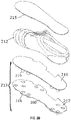
- FIGS. 2A-2C depict a second exemplary article of athletic footwear.
- FIG. 2A is a lateral side elevational view of the exemplary article of athletic footwear.
- FIG. 2B is an exploded perspective view of the second exemplary article of athletic footwear.
- FIG. 2C is a sectional view along 2-2 of the second exemplary article of athletic footwear.
- FIG. 2A is a lateral side elevational view of an exemplary article of footwear 210 that does not have a textile.
- the article of footwear 210 includes an upper 212 and a sole structure 213 having a plate 216 and a chassis 217.
- Chassis 217 includes edge portion 260 that extends about the perimeter of plate 216 when the sole structure is assembled.
- the upper 212 is bonded (e.g., adhesively, mechanically) to the plate 216 and chassis 217, including to edge portion 260.
- the edge portion 260 is disposed along biteline 270.
- the edge portion can be coupled directly or indirectly with the perimeter of the plate.
- the plate can provide rigidity, strength, and/or support to the sole structure without substantially adding weight.
- some exemplary sole structure aspects may include a plate having certain features that provide resistance to vertical bending, lateral bending, and/or torsion.
- an exemplary sole structure 3000 includes a plate 300 which can optionally include a reinforcing rib 310 longitudinally along the plate.
- the reinforcing rib 310 can, for example, include a hollow structure, and thus, may provide rigidity without adding substantial amounts of extra material, and therefore maintains a low weight.
- the plate 300 has an outer perimeter 350.
- An edge portion 360 is operably coupled with the plate 300 on at least a portion of the perimeter 350 of the plate 300.
- edge portion 360 is more flexible than the plate 300.
- flexural modulus is one measure of flexibility.
- the edge portion 360 can be formed integrally with the plate, e.g., injection molded with the plate 300 or onto the perimeter 350 of the plate 300.
- the edge portion 360 can be separately provided, e.g., formed as a separate component that is combined or joined with plate 300.
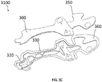
- another exemplary sole structure 3100 includes plate 300 operably coupled with a chassis 330 that comprises the edge portion 360.
- the chassis 330 may have a recess 320 in the chassis 330 that is configured to receive the plate 300, and an edge portion 360, disposed about the recess 320.
- Edge portion 360 may be formed integrally with the chassis 330, or it may be separately provided and combined or joined with the chassis 330.
- the edge portion 360 is disposed about the perimeter 350 of the plate 300.
- the sole structure when the sole structure includes a plate and a chassis configured to wrap around the plate and to engage or be attached to an upper when the sole structure is a component of an article of footwear, the sole structure also includes one or more textiles.
- a textile can be between the plate and the upper and can provide for improved bonding between the plate and the upper.
- a textile can also be positioned between the plate and the chassis.
- the textile can provide for improved adhesion between the plate and the chassis and/or the textile can be a decorative or ornamental textile.
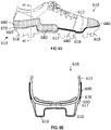
- the sole structure can include a decorative textile on the exterior or ground facing surface of the chassis. For example, as depicted in FIGS.
- the article of footwear 410 includes an upper 412 and a sole structure 413 having a plate 416, a chassis 417, and edge portion 460.
- the chassis 417 includes multiple traction elements 418.
- the traction elements 418 can be formed entirely from the chassis 417 material as pictured.
- one or more of the traction elements 418 can include a traction element tip (not pictured) configured to be ground-contacting.
- a textile 414 is positioned between the plate 416 and the chassis 417 and optionally edge portion 460.
- the article of footwear 410 can include a lasting board member 415 which can extend substantially the entire length of the plate 416.
- FIG. 5B is an exploded perspective view of the article of footwear 510 showing upper 512, heel plate 515, midfoot plate 516, and toe plate 517.
- one or more textiles may be disposed between upper 512 and heel plate 515, midfoot plate 516, and/or toe plate 517, respectively.
- the one or more textiles may be disposed between upper 512 and one or more of heel edge portion 565, midfoot edge portion 566, and/or toe edge portion 567
- a heel textile 535 may be disposed between upper 512 and the upper surface 525 of the heel plate 515 and, optionally, heel edge portion 565.
- Toe textile 537 may be disposed between upper 512 and the upper surface 527 of the toe plate 517 and, optionally, midfoot edge portion 567.
- a midfoot textile 536 may be disposed between upper 512 and the upper surface 526 of the midfoot plate 516 and, optionally, midfoot edge portion 566.
- the textiles can provide for improved bonding between upper 512, heel plate 515, midfoot plate 516, and toe plate 517 (and optionally, the respective edge portions 565, 566, 567).
- the sole structure is attached to the upper 512, as described herein, the heel edge portion 565, midfoot edge portion 566, and toe edge portion 567 are disposed along biteline 570.
- At least a portion of the edge portion may extend vertically above the biteline where an outsole and upper are attached, providing an extended edge portion.
- An extended edge portion may be continuous around the upper, or around the periphery of an outsole element such as a plate, or may be discontinuous or located only in select areas.
- the extended edge portion may extend around the entire outer periphery of the upper through each of the forefoot portion, the midfoot portion, and the heel portion.
- an extended edge portion may be present only on the forefoot portion of the upper, or on the forefoot portion and the heel portion of the upper.
- Extended edge portion may have a width as measured from the perimeter of the biteline to the outer edge of the extended edge portion.
- the extended edge portion may have a width of from about 0.25 millimeters to about 25 millimeters, or from about 0.5 millimeters to about 10 millimeters, or from about 1 millimeter to about 5 millimeters, or from about 1 millimeter to about 3 millimeters, as measured from the biteline to the perimeter of the extended edge portion.
- an article of footwear 710 includes upper 712 operably coupled with sole structure 713.
- Sole structure 713 includes plate 716 with one or more traction elements 718, and edge portion 760 that extends about the perimeter of the plate 716.
- biteline 770 is formed where perimeter of the plate 716 and upper 712 are joined.
- Edge portion 760 extends beyond biteline 770.
- edge portion 760 may have a substantially uniform height above the biteline 770 about the perimeter of the article of footwear 710, or it may have a height that varies about the perimeter of the article of footwear 710.
- the edge portion 760 may have a thickness of about 0.25 millimeters to about 5 millimeters, or from about 0.25 millimeters to about 4 millimeters, or from about 0.25 millimeters to about 3 millimeters.
- one or more of the extended edge portions 762, 764, 766 can include one or more decorative elements.
- extended edge portion 762 can include a first decorative portion disposed on the toe portion of the article of footwear 710
- extended edge portion 764 can include a second decorative portion 764 disposed on the medial portion of the article of footwear 710
- extended edge portion 766 can include a third decorative portion disposed on the heel portion of the article of footwear 710, or a combination thereof.
- Each of the decorative portions can include printing, coloring, or a combination thereof.
- the externally-facing or internally-facing sides of the extended edge portions 762, 764 and/or 766 can include printing directly on the edge portion, or can include a film (e.g., a printed film), or can include a textile (e.g., a printed textile).
- a film e.g., a printed film
- a textile e.g., a printed textile
- the printing or film or textile is disposed on the externally-facing side (in the assembled article of footwear), it can provide a decorative feature to the article of footwear 710.
- the edge portion 760 is at least partially transparent, it can provide a decorative feature which is visible through the edge portion 760
- an article of footwear can have a rand operably coupled with the upper and the sole structure.
- a rand is a component of an article of footwear that is disposed on an exterior surface of the article of footwear.
- the rand may be disposed on the upper, on the sole structure, or both.
- the rand may overlap the biteline where an outsole and upper are attached, and may extend vertically above and/or below the biteline.
- a rand may be continuous around the article of footwear, or may be discontinuous or located only in select areas. For example, a rand may extend around the entire outer periphery of the article through each of the forefoot portion, the midfoot portion, and the heel portion.
- FIGS. 6A-6E depict another exemplary article of athletic footwear having a rand.
- FIG. 6A is a lateral side elevational view of an exemplary article of footwear 610 that has a rand 680.
- the article of footwear 610 includes an upper 612 and a sole structure 613.
- Sole structure 613 includes edge portion 660 that extends about the perimeter of plate 616 when the sole structure is assembled. Edge portion 660 may be formed integrally with the plate 616, or it may be separately provided and combined or joined with the plate 616.
- Rand 680 is attached to the upper 612, the sole structure 613, or both, extending about the perimeter of the plate 616 and/or edge portion 660, so that when the sole structure 613 is attached to the upper 612, the rand 680 extends past the biteline 670.
- Rand 680 may be disposed at least partially between plate 616 and upper 612, such as shown in FIGS. 6A to 6E , or it may be disposed on the exterior surface of the article of footwear (see FIGS 8A and 8B ).
- rand 680 extends a certain height above biteline 670.
- Rand 680 may have a substantially uniform height above the biteline 670 about the perimeter of the article of footwear 610, or it may have a height that varies about the perimeter of the article of footwear 610 (see, e.g., FIG. 6D ).
- the rand 680 may have a greater height in the forefoot portion or in the heel portion of the article of footwear 610, as necessary or desired.
- Rand 680 has a certain thickness as measured from the surface of the upper to which it is attached. In some aspects, the thickness of the rand 680 may vary along the height of the rand 680.
- the rand may be disposed substantially entirely on the outer surface of the article of footwear.
- article of footwear 810 includes an upper 812 and a sole structure 813, including plate 816.
- Rand 880 is attached to the upper 812, as well as the plate 816, so that when the sole structure 813 is attached to the upper 812, the rand 880 covers the biteline 870.
- Rand 880 may be provided about the entirety of perimeter of the article of footwear 810, or only about a portion of article of footwear 810.
- rand 880 can include one or more decorative elements.
- rand 880 can include a first decorative portion disposed on the toe portion of the article of footwear 810, a second decorative portion disposed on the medial portion of the article of footwear 810, a third decorative portion disposed on the heel portion of the article of footwear 810, or a combination thereof.
- Each of the decorative portions can include printing, coloring, or a combination thereof.
- the externally-facing or internally-facing sides of the rand 880 can include printing directly on the rand, or can include a film (e.g., a printed film), or can include a textile (e.g., a printed textile).
- the printing or film or textile When the printing or film or textile is disposed on the externally-facing side (in the assembled article of footwear), it can provide a decorative feature to the article of footwear 810.
- the printing or film or textile When the printing or film or textile is disposed on the internally-facing side of the rand 880, and the rand 880 is at least partially transparent, it can provide a decorative feature which is visible through the rand 880.
- the sole structures can include a polyolefin plate, i.e. including a plate containing a first polyolefin resin composition.
- the first polyolefin resin composition can include any of the polyolefin resin compositions described herein.
- the sole structures can also include an elastomeric material containing a cured rubber and a hydrogel material, wherein in the elastomeric material, the hydrogel material is distributed throughout the cured rubber, and at least a portion of the hydrogel material present in the elastomeric material is physically entrapped by the cured rubber.
- the sole structures include an edge portion disposed about an outer perimeter of the polyolefin plate.
- the edge portion is generally more flexible (e.g., greater flexural modulus) than the polyolefin plate, to provide a more flexible attachment to the upper at the biteline.
- the edge portion can be formed integrally with the plate, or can be separately provide and attached or bonded to the plate.
- the edge portion can have one or more extended portions that at least partially wrap about the surface of the upper.
- the edge portion includes a second resin that is different from the first polyolefin resin.
- the second resin can include a polyolefin resin composition similar to the first polyolefin resin composition of the plate, but with a greater amount of resin modifier to provide a more flexible material.
- the second resin composition can include any other resin composition as described herein.
- the second resin can be any resin that is compatible with the first polyolefin resin and that has the necessary or desired durability and mechanical properties.
- the edge portion or the rand or both may comprise a hydrogel material.
- the hydrogel material may be coated on a target surface of the edge portion or the rand or both.
- the edge portion or the rand, or both may comprise an elastomeric material containing a cured rubber and a hydrogel material, wherein in the elastomeric material, the hydrogel material is distributed throughout the cured rubber, and at least a portion of the hydrogel material present in the elastomeric material is physically entrapped by the cured rubber.
- the article may optionally include a rand disposed about at least part of the plate and/or the edge portion.
- the optional rand overlaps and extends beyond the biteline when the sole structure is bonded to the upper.
- the rand can be separately provided and attached or bonded to the plate, edge portion, upper, or a combination thereof.
- the optional rand may comprise a material that provides properties and characteristics necessary or desirable for that area of the article of footwear, such as, for example, additional abrasion resistance or water resistance.
- the sole structures can include a textile on one or more surfaces of the plate.
- the first side can be configured to be ground-facing when the plate is a component of an article of footwear and the second side can be configured to be upward facing.
- the textile is on one or both of the first side and the second side.
- the textile can provide for improved bonding between the plate and other components of the sole structure, e.g. between the plate and a chassis.
- the textile can also provide for improved bonding between the plate and the upper when the sole structure is a component of an article of footwear.
- the textile is a patterned or decorative textile.
- the textile can extend beyond the perimeter of the plate, e.g., so that it overlaps the edge portion on the first side of the plate, the second side of the plate, or both.
- the chassis can include a hydrogel material.
- the hydrogel material may be coated on a target surface of the chassis.
- the chassis can include an elastomeric material containing a cured rubber and a hydrogel material, wherein in the elastomeric material, the hydrogel material is distributed throughout the cured rubber, and at least a portion of the hydrogel material present in the elastomeric material is physically entrapped by the cured rubber.
- the traction elements are made from the same or nearly the same resin composition as the plate, or as edge portion. In other aspects, the traction elements are made from a third resin that is different from the first polyolefin resin and the second resin. In some aspects, the sole structure includes a chassis and the chassis is made from the second resin or the third resin.
- the third resin can include a polystyrene, a polyethylene, an ethylene- ⁇ -olefin copolymer, an ethylene-propylene rubber (EPDM), a polybutene, a polyisobutylene, a poly-4-methylpent-1-ene, a polyisoprene, a polybutadiene, an ethylene-methacrylic acid copolymer, an olefin elastomer, a copolymer thereof, or a blend or mixture thereof.
- the third resin includes about 20 percent, about 10 percent, or less of a polyolefin.
- the third resin can include about 20 percent, about 10 percent, or less of polypropylene.
- the third resin can include an ethylene-propylene rubber (EPDM) dispersed in a polypropylene.
- the third resin can include a block copolymer comprising a polystyrene block.
- the block copolymer comprises can be, for example. a copolymer of styrene and one or both of ethylene and butylene.
- the third resin can be any resin that is compatible with the polyolefin resin and that has the necessary or desired durability and mechanical properties.
- the third resin e.g. a polystyrene, a polyethylene, an ethylene- ⁇ -olefin copolymer, an ethylene-propylene rubber (EPDM), a polybutene, a polyisobutylene, a poly-4-methylpent-1-ene, a polyisoprene, a polybutadiene, an ethylene-methacrylic acid copolymer, an olefin elastomer, a copolymer thereof, or a blend or mixture thereof
- EPDM ethylene-propylene rubber
- third resin containing an ethylene-propylene rubber (EPDM) dispersed in a polypropylene, or containing a block copolymer having a polystyrene block; and wherein the block copolymer includes a copolymer of styrene and one or both of ethylene and butylene, have been found to be particularly useful in ground-contacting portions of traction elements, as these compositions both bond well to the resin compositions of the present disclosure, and can provide an even higher level of abrasion-resistance than the resin compositions of the present disclosure, which may be desired in the ground-contacting portions of traction elements.
- EPDM ethylene-propylene rubber
- the polyhydric alcohol can include those selected from the group consisting of acyclic polyols such as xylitol and sorbitol and acyclic deoxy polyols such as 1,2,3-trideoxynonitol or 1,2,3-trideoxynon-1-enitol.
- the aromatic aldehyde can include those selected from the group consisting of benzaldehyde and substituted benzaldehydes.
- Two polyolefin resin compositions can have polymeric components with are substantially the same, in that both the polymeric components consist of substantially the same types of polymers in substantially the same concentrations.
- Two polyolefin resin compositions can have substantially similar polymeric components, in that both the polymeric components consist of substantially the same types of polymers but in substantially different concentrations (e.g., concentrations which differ by at least 2 weight percent).
- concentrations e.g., concentrations which differ by at least 2 weight percent.
- the non-polymeric materials present in each of the polyolefin resin compositions may differ from each other.
- the first of two polyolefin resin compositions sharing substantially the same polymeric components or substantially similar polymeric components may include a first pigment
- the second of the two polyolefin resin compositions may include a second pigment which is different from the first pigment and which is not present in the first polyolefin resin composition, or which is present in different concentrations in the first and second polyolefin resin compositions.
- the disclosed polyolefin resin compositions can include any of a variety of polyolefin copolymers having the necessary or desired features.
- the copolymers can be alternating copolymers or random copolymers or block copolymers or graft copolymers. In some aspects, the copolymers are random copolymers. In some aspects, the copolymer includes a plurality of repeat units, with each of the plurality of repeat units individually derived from an alkene monomer having about 1 to about 6 carbon atoms.
- the copolymer includes a plurality of repeat units, with each of the plurality of repeat units individually derived from a monomer selected from the group consisting of ethylene, propylene, 4-methyl-1-pentene, 1-butene, 1-octene, and a combination thereof.
- the polyolefin copolymer includes a plurality of repeat units each individually selected from Formula 1A-1D.
- the polyolefin copolymer includes a first plurality of repeat units having a structure according to Formula 1A, and a second plurality of repeat units having a structure selected from Formula 1B-1D.
- the polyolefin copolymer includes a plurality of repeat units each individually having a structure according to Formula 2 where R 1 is a hydrogen or a substituted or unsubstituted, linear or branched, C 1 -C 12 alkyl. C 1 -C 6 alkyl, C1-C3 alkyl, C1-C12 heteroalkyl, C1-C6 heteroalkyl, or C1-C3 heteroalkyl.
- each of the repeat units in the first plurality of repeat units has a structure according to Formula 1A above
- each of the repeat units in the second plurality of repeat units has a structure according to Formula 2 above.
- the polyolefin copolymer is a random copolymer of a first plurality of repeat units and a second plurality of repeat units, and each repeat unit in the first plurality of repeat units is derived from ethylene and each repeat unit in the second plurality of repeat units is derived from a second olefin.
- the second olefin is an alkene monomer having about 1 to about 6 carbon atoms.
- the second olefin includes propylene, 4-methyl-1-pentene, 1-butene, or other linear or branched terminal alkenes having about 3 to 12 carbon atoms.
- the polyolefin copolymer can include ethylene, i.e. can include repeat units derived from ethylene such as those in Formula 1A.
- the polyolefin copolymer includes about 1 percent to about 5 percent, about 1 percent to about 3 percent, about 2 percent to about 3 percent, or about 2 percent to about 5 percent ethylene by weight based upon a total weight of the polyolefin copolymer.
- the polyolefin resin compositions can be made without the need for polyurethanes and/or without the need for polyamides.
- the polyolefin copolymer is substantially free of polyurethanes.
- the polymer chains of the polyolefin copolymer are substantially free of urethane repeat units.
- the resin composition is substantially free of polymer chains including urethane repeat units.
- the polyolefin copolymer is substantially free of polyamide.
- the polymer chains of the polyolefin copolymer are substantially free of amide repeat units.
- the resin composition is substantially free of polymer chains including amide repeat units.
- the polyolefin copolymer includes polypropylene or is a polypropylene copolymer.
- the polymeric component of the resin composition i.e., the portion of the resin composition that is formed by all of the polymers present in the composition
- the resin composition is provided including a polypropylene copolymer, and an effective amount of a polymeric resin modifier, wherein the resin composition has an abrasion loss as described above, and wherein the effective amount of the polymeric resin modifier is an amount effective to allow the resin composition to pass a flex test pursuant to the Cold Ross Flex Test using the Plaque Sampling Procedure.
- the effective amount of the polymeric resin modifier is an amount effective to allow the resin composition to pass a flex test pursuant to the Cold Ross Flex Test using the Plaque Sampling Procedure without a significant change in an abrasion loss as compared to an abrasion loss of a second resin composition identical to the resin composition except without the polymeric resin modifier when measured pursuant to Abrasion Loss Test using the Neat Material Sampling Procedure.
- the polypropylene copolymer can include a random copolymer, e.g. a random copolymer of ethylene and propylene.
- the polypropylene copolymer can include about 80 percent to about 99 percent, about 85 percent to about 99 percent, about 90 percent to about 99 percent, or about 95 percent to about 99 percent propylene repeat units by weight based upon a total weight of the polypropylene copolymer.
- the polypropylene copolymer includes about 1 percent to about 5 percent, about 1 percent to about 3 percent, about 2 percent to about 3 percent, or about 2 percent to about 5 percent ethylene by weight based upon a total weight of the polypropylene copolymer.
- the polypropylene copolymer is a random copolymer including about 2 percent to about 3 percent of a first plurality of repeat units by weight and about 80 percent to about 99 percent by weight of a second plurality of repeat units based upon a total weight of the polypropylene copolymer; wherein each of the repeat units in the first plurality of repeat units has a structure according to Formula 1A above and each of the repeat units in the second plurality of repeat units has a structure according to Formula 1B above.
- the polymeric resin modifier leads to a decrease in the percent crystallinity (percent crystallinity) of the resin composition.
- the resin composition has a percent crystallization (percent crystallization) that is at least 6, at least 5, at least 4, at least 3, or at least 2 percentage points less than a percent crystallization (percent crystallization) of the otherwise same resin composition except without the polymeric resin modifier when measured according to the Crystallinity Test using the Neat Material Sampling Procedure.
- the effective amount of the polymeric resin modifier is about 5 percent to about 30 percent, about 5 percent to about 25 percent, about 5 percent to about 20 percent, about 5 percent to about 15 percent, about 5 percent to about 10 percent, about 10 percent to about 15 percent, about 10 percent to about 20 percent, about 10 percent to about 25 percent, or about 10 percent to about 30 percent by weight based upon a total weight of the resin composition. In some aspects, the effective amount of the polymeric resin modifier is about 20 percent, about 15 percent, about 10 percent, about 5 percent, or less by weight based upon a total weight of the resin composition.
- the polymeric resin modifier can include any of a variety of exemplary resin modifiers described herein.
- the polymeric resin modifier is a metallocene catalyzed copolymer primarily composed of isotactic propylene repeat units with about 11 percent by weight-15 percent by weight of ethylene repeat units based on a total weight of metallocene catalyzed copolymer randomly distributed along the copolymer.
- the polymeric resin modifier includes about 10 percent to about 15 percent ethylene repeat units by weight based upon a total weight of the polymeric resin modifier.
- the polymeric resin modifier includes about 10 percent to about 15 percent repeat units according to Formula 1A above by weight based upon a total weight of the polymeric resin modifier.
- the polymeric resin modifier is a copolymer of repeat units according to Formula 1B above, and the repeat units according to Formula 1B are arranged in an isotactic stereochemical configuration.
- a clarifying agent in the plate (in the polyolefin resin), in the edge portion, and/or, when a chassis is present, in the chassis.
- the clarifying agent can allow for clear visibility of a textile through the plate.
- the clarifying agent can be present in any suitable amount to provide sufficient optical clarity of the final plate or sole structure. In some aspects, the clarifying agent is present in an amount from about 0.5 percent by weight to about 5 percent by weight or about 1.5 percent by weight to about 2.5 percent by weight based upon a total weight of the polyolefin resin.
- the polyhydric alcohol can include those selected from the group consisting of acyclic polyols such as xylitol and sorbitol and acyclic deoxy polyols such as 1,2,3-trideoxynonitol or 1,2,3-trideoxynon-1-enitol.
- the aromatic aldehyde can include those selected from the group consisting of benzaldehyde and substituted benzaldehydes.
- the disclosed plate composition ally comprises a first polyolefin composition.
- the first polyolefin resin composition can be any of a variety of polyolefin resin compositions described herein having the abrasion resistance and flexural durability suitable for use in the articles and components described herein.
- a first polyolefin resin composition includes a polyolefin copolymer, and an effective amount of a polymeric resin modifier. The effective amount of the resin modifier in the first polyolefin resin composition provides improved flexural durability while maintaining a suitable abrasion resistance.
- the effective amount of the polymeric resin modifier in the first polyolefin resin composition is an amount effective to allow the first polyolefin resin composition to pass a flex test pursuant to the Cold Ross Flex Test using the Plaque Sampling Procedure.
- the first polyolefin resin composition can still have a suitable abrasion loss when measured pursuant to Abrasion Loss Test using the Neat Material Sampling Procedure.
- a comparable first polyolefin resin composition except without the polymeric resin modifier does not pass the cold Ross flex test using the Neat Material Sampling Procedure.
- the first polyolefin resin composition has an abrasion loss of about 0.05 cubic centimeters (cm 3 ) to about 0.1 cubic centimeters (cm 3 ), about 0.07 cubic centimeters (cm 3 ) to about 0.1 cubic centimeters (cm 3 ), about 0.08 cubic centimeters (cm 3 ) to about 0.1 cubic centimeters (cm 3 ), or about 0.08 cubic centimeters (cm 3 ) to about 0.11 cubic centimeters (cm 3 ) pursuant to Abrasion Loss Test using the Neat Material Sampling Procedure.
- the effective amount of the polymeric resin modifier in the first polyolefin resin composition is about 5 percent to about 30 percent, about 5 percent to about 25 percent, about 5 percent to about 20 percent, about 5 percent to about 15 percent, about 5 percent to about 10 percent, about 10 percent to about 15 percent, about 10 percent to about 20 percent, about 10 percent to about 25 percent, or about 10 percent to about 30 percent by weight based upon a total weight of the first polyolefin resin composition. In some aspects, the effective amount of the polymeric resin modifier is about 20 percent, about 15 percent, about 10 percent, about 5 percent, or less by weight based upon a total weight of the first polyolefin resin composition.
- the edge portion comprises a second resin composition.
- the second resin composition is different from the first polyolefin resin composition and can be any of a variety of resin compositions that provide a higher degree of flexibility than the plate.
- the second resin can be any of a variety of resin compositions providing necessary or desired properties to the edge portion.
- the edge portion has a lower flexural modulus than the plate.
- the edge portion has a flexural modulus that is at least 10 percent, or at least 15 percent, or at least 20 percent or at least 25 percent, or at least 30 percent or at least 35 percent lower than a flexural modulus of the plate.
- the edge portion has a lower Durometer hardness than the plate.
- the edge portion has a Durometer hardness that is at least 10 percent, or at least 15 percent or at least 20 percent or at least 25 percent, or at least 30 percent or at least 35 percent lower than a Durometer hardness of the plate
- the second resin is any material that is compatible with one or more materials in the sole structure. In some aspects, the second resin is compatible with one or more materials in the article of footwear.
- the second resin of the edge portion can be bonded to an upper using a conventional water-borne polyurethane shoe adhesive. In some aspects, the second resin is any material that can be any material that has a bonding score which is at least 20 percent greater, or at least 25 percent greater, or at least 30 percent greater than the bonding score of the first polyolefin resin when bonded to the material of the upper.
- the second resin is a second polyolefin resin composition as described generally above.
- the second polyolefin resin composition can include a second polyolefin copolymer, and an effective amount of a polymeric resin modifier.
- the second polyolefin copolymer can comprise any of the exemplary polyolefin copolymers described herein.
- the second polyolefin copolymer may be the same as or different than the first polyolefin copolymer.
- the polymeric resin modifier of the second polyolefin composition can include any of the exemplary resin modifiers described herein.
- the effective amount of the resin modifier is that which provides greater flexibility or lower rigidity as compared to the first polyolefin resin composition. Flexural modulus is an example of a measure of flexibility. Durometer hardness is an example of rigidity.
- the effective amount of the polymeric resin modifier in the second polyolefin composition is at least 2 weight percent greater than the amount of the polymeric resin modifier in the first polyolefin composition.
- the effective amount of the polymeric resin modifier in the second polyolefin composition can be at least 5 weight percent, or at least 10 weight percent, or at least 15 weight percent greater than the amount of the polymeric resin modifier in the first polyolefin composition, based on a total weight of each composition.
- the effective amount of the polymeric resin modifier in the second polyolefin composition is at least 5 weight percent, or at least 10 weight percent, or at least 20 weight percent, or at least 30 weight percent.
- the effective amount of the polymeric resin modifier in the second polyolefin composition can range from about 5 weight percent to about 50 weight percent, about 5 weight percent to about 40 weight percent, about 5 weight percent to about 30 weight percent, about 5 weight percent to about 20 weight percent, about 5 weight percent to about 15 weight percent, about 10 weight percent to about 30 weight percent, about 10 weight percent to about 25 weight percent, about 10 weight percent to about 20 weight percent, or about 10 weight percent to about 15 weight percent, based upon a total weight of the second resin composition.
- the sole structure includes one or more traction elements, and the one or more traction elements include the second resin composition. In some aspects, the sole structure includes a chassis and the chassis includes the second resin.
- the second resin can include a polystyrene, a polyethylene, an ethylene- ⁇ -olefin copolymer, an ethylene-propylene rubber (EPDM), a polybutene, a polyisobutylene, a poly-4-methylpent-1-ene, a polyisoprene, a polybutadiene, an ethylene-methacrylic acid copolymer, an olefin elastomer, a copolymer thereof, or a blend or mixture thereof.
- the second resin includes about 20 percent, about 10 percent, or less of a polyolefin.
- the second resin can include about 20 percent, about 10 percent, or less of polypropylene.
- the second resin can include an ethylene-propylene rubber (EPDM) dispersed in a polypropylene.
- the second resin can include a block copolymer comprising a polystyrene block.
- the block copolymer comprises can be, for example. a copolymer of styrene and one or both of ethylene and butylene.
- the second resin can be any resin that is compatible with the polyolefin resin and that has the appropriate durability and mechanical properties.
- the second resin e.g. a polystyrene, a polyethylene, an ethylene- ⁇ -olefin copolymer, an ethylene-propylene rubber (EPDM), a polybutene, a polyisobutylene, a poly-4-methylpent-1-ene, a polyisoprene, a polybutadiene, an ethylene-methacrylic acid copolymer, an olefin elastomer, a copolymer thereof, or a blend or mixture thereof
- EPDM ethylene-propylene rubber
- the optional rand comprises a rand polymeric material.
- the rand polymeric material can comprise a resin composition that is the same or different from the first polyolefin resin composition.
- the rand polymeric material can be any of a variety of polymeric materials that provide a desired property to the article of footwear, e.g., increased abrasion resistance.
- the rand polymeric material is any material that is compatible with one or more materials in the article of footwear.
- the rand polymeric material can be bonded to an upper using a conventional water-bome polyurethane shoe adhesive.
- the rand polymeric material can include a polypropylene, polystyrene, a polyethylene, an ethylene- ⁇ -olefin copolymer, an ethylene-propylene rubber (EPDM), a polybutene, a polyisobutylene, a poly-4-methylpent-1-ene, a polyisoprene, a polybutadiene, an ethylene-methacrylic acid copolymer, an olefin elastomer, a copolymer thereof, or a blend or mixture thereof.
- EPDM ethylene-propylene rubber
- the rand polymeric material is an elastomeric material. In some aspects, the rand polymeric material is a foamed material.
- the hydrogel material comprises a polyurethane hydrogel.
- the hydrogel material can comprise a polyamide hydrogel, a polyurea hydrogel, a polyester hydrogel, a polycarbonate hydrogel, a polyetheramide hydrogel, a hydrogel formed of addition polymers of ethylenically unsaturated monomers, copolymers thereof (e.g., co-polyesters, co-polyethers, co-polyamides, co-polyurethanes, co-polyolefins), and combinations thereof. Additional details are provided herein.
- extemally facing layer refers to the position the element is intended to be in when the element is present in an article during normal use. If the article is footwear, the element is positioned toward the ground during normal use by a wearer when in a standing position, and thus can contact the ground including unpaved surfaces when the footwear is used in a conventional manner, such as standing, walking or running on an unpaved surface. In other words, even though the element may not necessarily be facing the ground during various steps of manufacturing or shipping, if the element is intended to face the ground during normal use by a wearer, the element is understood to be externally-facing or more specifically for an article of footwear, ground-facing.
- the externally facing (e.g., ground-facing) surface can be positioned toward the ground during conventional use but may not necessarily come into contact the ground.
- the terminal ends of traction elements on the outsole may directly contact the ground, while portions of the outsole located between the traction elements do not.
- the portions of the outsole located between the traction elements are considered to be externally facing (e.g., ground-facing) even though they may not directly contact the ground in all circumstances.
- the hydrogel material and articles incorporating the hydrogel material can prevent or reduce the accumulation of soil on the externally-facing layer of the material during wear on unpaved surfaces.
- soil can include any of a variety of materials commonly present on a ground or playing surface and which might otherwise adhere to an outsole or exposed midsole of a footwear article. Soil can include inorganic materials such as mud, sand, dirt, and gravel; organic matter such as grass, turf, leaves, other vegetation, and excrement; and combinations of inorganic and organic materials such as clay. Additionally, soil can include other materials such as pulverized rubber which may be present on or in an unpaved surface.
- the hydrogel material in accordance with the present disclosure when sufficiently wet with water (including water containing dissolved, dispersed or otherwise suspended materials) can provide compressive compliance and/or expulsion of uptaken water.
- the compressive compliance of the wet hydrogel material, the expulsion of liquid from the wet material, or both in combination can disrupt the adhesion of soil on or at the outsole, or the cohesion of the particles to each other, or can disrupt both the adhesion and cohesion.
- This disruption in the adhesion and/or cohesion of soil is believed to be a responsible mechanism for preventing (or otherwise reducing) the soil from accumulating on the footwear outsole (due to the presence of the wet material).
- This disruption in the adhesion and/or cohesion of soil is believed to be a responsible mechanism for preventing (or otherwise reducing) the soil from accumulating on the footwear outsole (due to the presence of the hydrogel material).
- preventing soil from accumulating on the bottom of footwear can improve the performance of traction elements present on the outsole during wear on unpaved surfaces, can prevent the footwear from gaining weight due to accumulated soil during wear, can preserve ball handling performance of the footwear, and thus can provide significant benefits to wearer as compared to an article of footwear without the material present on the outsole.
- the swelling of the material can be observed as an increase in material thickness from the dry-state thickness of the material, through a range of intermediate-state thicknesses as additional water is absorbed, and finally to a saturated-state thickness material, which is an average thickness of the material when fully saturated with water.
- the saturated-state thickness for the fully saturated material can be greater than 150 percent, greater than 200 percent, greater than 250 percent, greater than 300 percent, greater than 350 percent, greater than 400 percent, or greater than 500 percent, of the dry-state thickness for the same material (e.g., the hydrogel material), as characterized by the Swelling Capacity Test.
- the saturated-state thickness for the fully saturated material can be about 150 percent to 500 percent, about 150 percent to 400 percent, about 150 percent to 300 percent, or about 200 percent to 300 percent of the dry-state thickness for the same material.
- suitable average thicknesses for the material in a wet state (referred to as a saturated-state thickness) can be about 0.2 millimeters to 10 millimeters, about 0.2 millimeters to 5 millimeters, about 0.2 millimeters to 2 millimeters, about 0.25 millimeters to 2 millimeters, or about 0.5 millimeters to 1 millimeter.
- the hydrogel material or layered material in neat form can have an increase in thickness at 1 hour of about 35 percent to 400 percent, about 50 percent to 300 percent, or about 100 percent to 200 percent, as characterized by the Swelling Capacity Test.
- the material in neat form can have an increase in thickness at 24 hours of about 45 percent to 500 percent, about 100 percent to 400 percent, or about 150 percent to 300 percent.
- the outsole film in neat form can have an increase in film volume at 1 hour of about 50 percent to 500 percent, about 75 percent to 400 percent, or about 100 percent to 300 percent.
- the hydrogel material can quickly take up water that is in contact with the material.
- the hydrogel material can take up water from mud and wet grass, such as during a warmup period prior to a competitive match.
- the hydrogel material can be pre-conditioned with water so that the material is partially or fully saturated, such as by spraying or soaking the material with water prior to use.
- the hydrogel material can exhibit an overall water uptake capacity of about 25 percent to 225 percent as measured in the Water Uptake Capacity Test over a soaking time of 24 hours using the Component Sampling Procedure, as will be defined below.
- the overall water uptake capacity exhibited by the hydrogel material is in the range of about 30 percent to about 200 percent; alternatively, about 50 percent to about 150 percent; alternatively, about 75 percent to about 125 percent.
- the term "overall water uptake capacity" is used to represent the amount of water by weight taken up by the hydrogel material as a percentage by weight of dry hydrogel material.
- the procedure for measuring overall water uptake capacity includes measurement of the "dry" weight of the hydrogel material, immersion of the hydrogel material in water at ambient temperature (-23 degrees Celsius) for a predetermined amount of time, followed by re-measurement of the weight of the hydrogel material when "wet".
- the procedure for measuring the overall weight uptake capacity according to the Water Uptake Capacity Test using the Component Sampling Procedure is described below.
- the overall water uptake capacity and the water uptake rate can be dependent upon the amount of the hydrogel material that is present in the material (e.g., layered material).
- the hydrogel material can be characterized by a water uptake capacity of 50 percent to 2000 percent as measured according to the Water Uptake Capacity Test using the Neat Material Sampling Procedure.
- the water uptake capacity of the hydrogel material is determined based on the amount of water by weight taken up by the hydrogel material as a percentage by weight of dry hydrogel material.
- the water uptake capacity exhibited by the hydrogel material is in the range of about 100 percent to about 1500 percent; alternatively, in the range of about 300 percent to about 1200 percent.
- the surface of the hydrogel material (e.g., layered material), including the surface of an article can also exhibit a low coefficient of friction when the material is wet.
- suitable coefficients of friction for the hydrogel material in a dry state are less than 1.5, for instance ranging from 0.3 to 1.3, or from 0.3 to 0.7, as characterized by the Coefficient of Friction Test.
- the Coefficient of Friction Test can be conducted on a sample obtained in accordance with the Component Sampling Procedure, or the Neat material Sampling Procedure.
- the hydrogel material exhibits a reduction in the storage modulus from its dry state to its wet state (50 percent RH) of more than 20 percent, more than 40 percent, more than 60 percent, more than 75 percent, more than 90 percent, or more than 99 percent, relative to the storage modulus in the dry state, and as characterized by the Storage Modulus Test with the Neat Material Sampling Process.
- the dry-state storage modulus of the hydrogel material is greater than its wet-state (50 percent RH) storage modulus by more than 25 megaPascals (MPa), by more than 50 megapascals, by more than 100 megapascals, by more than 300 megapascals, or by more than 500 megapascals, for example ranging from 25 megapascals to 800 megapascals, from 50 megapascals to 800 megapascals, from 100 megapascals to 800 megapascals, from 200 megapascals to 800 megapascals, from 400 megapascals to 800 megapascals, from 25 megapascals to 200 megapascals, from 25 megapascals to 100 megapascals, or from 50 megapascals to 200 megapascals.
- MPa megaPascals
- 50 megapascals to 800 megapascals from 100 megapascals to 800 megapascals
- 200 megapascals to 800 megapascals from 400 megapascals to 800 megapascals
- the dry-state storage modulus can range from 40 megapascals to 800 megapascals, from 100 megapascals to 600 megapascals, or from 200 megapascals to 400 megapascals, as characterized by the Storage Modulus Test. Additionally, the wet-state storage modulus can range from 0.003 megapascals to 100 megapascals, from 1 megapascals to 60 megapascals, or from 20 megapascals to 40 megapascals.
- the hydrogel material exhibits a reduction in the storage modulus from its dry state to its wet state (90 percent RH) of more than 20 percent, more than 40 percent, more than 60 percent, more than 75 percent, more than 90 percent, or more than 99 percent, relative to the storage modulus in the dry state, and as characterized by the Storage Modulus Test with the Neat Material Sampling Procedure.
- the dry-state storage modulus of the hydrogel material is greater than its wet-state (90 percent RH) storage modulus by more than 25 megaPascals (MPa), by more than 50 megapascals, by more than 100 megapascals, by more than 300 megapascals, or by more than 500 megapascals, for example ranging from 25 megapascals to 800 megapascals, from 50 megapascals to 800 megapascals, from 100 megapascals to 800 megapascals, from 200 megapascals to 800 megapascals, from 400 megapascals to 800 megapascals, from 25 megapascals to 200 megapascals, from 25 megapascals to 100 megapascals, or from 50 megapascals to 200 megapascals.
- MPa megaPascals
- 50 megapascals to 800 megapascals from 100 megapascals to 800 megapascals
- 200 megapascals to 800 megapascals from 400 megapascals to 800 megapascals
- the hydrogel material can also exhibit a reduction in its glass transition temperature from the dry state (when equilibrated at 0 percent relative humidity (RH) to the wet state (when equilibrated at 90 percent RH). While not wishing to be bound by theory, it is believed that the water taken up by the hydrogel material plasticizes the material, which reduces its storage modulus and its glass transition temperature, rendering the hydrogel material more compliant (e.g., compressible, expandable, and stretchable).
- RH relative humidity
- the hydrogel material can exhibit a reduction in glass transition temperature ( ⁇ T g ) from its dry-state (0 percent RH) glass transition temperature to its wet-state glass transition (90 percent RH) temperature of more than a 5 degrees Celsius difference, more than a 6 degrees Celsius difference, more than a 10 degrees Celsius difference, or more than a 15 degrees Celsius difference, as characterized by the Glass Transition Temperature Test with the Neat Material Sampling Procedure.
- the reduction in glass transition temperature ( ⁇ T g ) can range from more than a 5 degrees Celsius difference to a 40 degrees Celsius difference, from more than a 6 degrees Celsius difference to a 50 degrees Celsius difference, form more than a 10 degrees Celsius difference to a 30 degrees Celsius difference, from more than a 30 degrees Celsius difference to a 45 degrees Celsius difference, or from a 15 degrees Celsius difference to a 20 degrees Celsius difference.
- the hydrogel material can also exhibit a dry glass transition temperature ranging from -40 degrees Celsius to -80 degrees Celsius, or from -40 degrees Celsius to -60 degrees Celsius.
- the total amount of water that the hydrogel material can take up depends on a variety of factors, such as its composition (e.g., its hydrophilicity), its cross-linking density, its thickness, and the like.
- the water uptake capacity and the water uptake rate of the hydrogel material are dependent on the size and shape of its geometry, and are typically based on the same factors. Conversely, the water uptake rate is transient and can be defined kinetically.
- the three primary factors for water uptake rate for hydrogel material present given part geometry include time, thickness, and the exposed surface area available for taking up water.
- the saturated-state thickness of the hydrogel material preferably remains less than the length of the traction element.
- This selection of the hydrogel material and its corresponding dry and saturated thicknesses ensures that the traction elements can continue to provide ground-engaging traction during use of the footwear, even when the hydrogel material is in a fully swollen state.
- the average clearance difference between the lengths of the traction elements and the saturated-state thickness of the hydrogel material is desirably at least 8 millimeters.
- the average clearance distance can be at least 9 millimeters, 10 millimeters, or more.
- the compliance of the hydrogel material can also increase from being relatively stiff (i.e., dry-state) to being increasingly stretchable, compressible, and malleable (i.e., wet-state).
- the increased compliance accordingly can allow the hydrogel material to readily compress under an applied pressure (e.g., during a foot strike on the ground), and in some aspects, to quickly expel at least a portion of its retained water (depending on the extent of compression). While not wishing to be bound by theory, it is believed that this compressive compliance alone, water expulsion alone, or both in combination can disrupt the adhesion and/or cohesion of soil, which prevents or otherwise reduces the accumulation of soil.
- the compressed hydrogel material is capable of quickly re-absorbing water when the compression is released (e.g., liftoff from a foot strike during normal use).
- the hydrogel material can dynamically expel and repeatedly take up water over successive foot strikes, particularly from a wet surface.
- the hydrogel material can continue to prevent soil accumulation over extended periods of time (e.g., during an entire competitive match), particularly when there is ground water available for re-uptake.
- the hydrogel material In addition to being effective at preventing soil accumulation, the hydrogel material has also been found to be sufficiently durable for its intended use on the ground-contacting side of the article of footwear. In various aspects, the useful life of the hydrogel material (and footwear containing it) is at least 10 hours, 20 hours, 50 hours, 100 hours, 120 hours, or 150 hours of wear.
- the terms “take up”, “taking up”, “uptake”, “uptaking”, and the like refer to the drawing of a liquid (e.g., water) from an external source into the hydrogel material, such as by absorption, adsorption, or both.
- a liquid e.g., water
- water refers to an aqueous liquid that can be pure water, or can be an aqueous carrier with lesser amounts of dissolved, dispersed or otherwise suspended materials (e.g., particulates, other liquids, and the like).
- the externally facing layer includes the first material.
- the first material comprises a hydrogel material.
- the hydrogel material can comprise a polymeric hydrogel.
- the polymeric hydrogel can comprise or consist essentially of a polyurethane hydrogel.
- Polyurethane hydrogels are prepared from one or more diisocyanate and one or more hydrophilic diol.
- the polymer may also include a hydrophobic diol in addition to the hydrophilic diol. The polymerization is normally carried out using roughly an equivalent amount of the diol and diisocyanate.
- hydrophilic diols are polyethylene glycols or copolymers of ethylene glycol and propylene glycol.
- the diisocyanate can be selected from a wide variety of aliphatic or aromatic diisocyanates.
- the hydrophobicity of the resulting polymer is determined by the amount and type of the hydrophilic diols, the type and amount of the hydrophobic diols, and the type and amount of the diisocyanates. Additional details regarding polyurethane are provided herein.
- the polymeric hydrogel can comprise or consist essentially of a polyurea hydrogel.
- Polyurea hydrogels are prepared from one or more diisocyanate and one or more hydrophilic diamine.
- the polymer may also include a hydrophobic diamine in addition to the hydrophilic diamines.
- the polymerization is normally carried out using roughly an equivalent amount of the diamine and diisocyanate.
- Typical hydrophilic diamines are amine-terminated polyethylene oxides and amine-terminated copolymers of polyethylene oxide/polypropylene. Examples are Jeffamine ® diamines sold by Huntsman (The Woodlands, TX, USA).
- the diisocyanate can be selected from a wide variety of aliphatic or aromatic diisocyanates.
- the hydrophobicity of the resulting polymer is determined by the amount and type of the hydrophilic diamine, the type and amount of the hydrophobic amine, and the type and amount of the diisocyanate. Additional details regarding polyurea
- the lactone is polymerized on each end of the hydrophilic diol to produce a triblock polymer.
- these triblock segments can be linked together to produce a multiblock polymer by reaction with a dicarboxylic acid. Additional details regarding polyurea are provided herein.
- the polymeric hydrogel can comprise or consist essentially of a polycarbonate hydrogel.
- Polycarbonates are typically prepared by reacting a diol with phosgene or a carbonate diester.
- a hydrophilic polycarbonate is produced when part or all of the diol is a hydrophilic diol.
- hydrophilic diols are hydroxyl terminated polyethers of ethylene glycol or polyethers of ethylene glycol with propylene glycol.
- a second hydrophobic diol can also be included to control the polarity of the final polymer. Additional details regarding polycarbonate are provided herein.
- the polymeric hydrogel can comprise or consist essentially of a polyetheramide hydrogel.
- Polyetheramides are prepared from dicarboxylic acids (or dicarboxylic acid derivatives) and polyether diamines (a polyether terminated on each end with an amino group). Hydrophilic amine-terminated polyethers produce hydrophilic polymers that will swell with water. Hydrophobic diamines can be used in conjunction with hydrophilic diamines to control the hydrophilicity of the final polymer.
- the type dicarboxylic acid segment can be selected to control the polarity of the polymer and the physical properties of the polymer.
- Typical hydrophilic diamines are amine-terminated polyethylene oxides and amine-terminated copolymers of polyethylene oxide/polypropylene. Examples are Jeffamine ® diamines sold by Huntsman (The Woodlands, TX, USA). Additional details regarding polyetheramide are provided herein.
- the polymeric hydrogel can comprise or consist essentially of a hydrogel formed of addition polymers of ethylenically unsaturated monomers.
- the addition polymers of ethylenically unsaturated monomers can be random polymers. Polymers prepared by free radical polymerization of one of more hydrophilic ethylenically unsaturated monomer and one or more hydrophobic ethylenically unsaturated monomers.
- hydrophilic monomers are acrylic acid, methacrylic acid, 2-acrylamido-2-methylpropane sulphonic acid, vinyl sulphonic acid, sodium p-styrene sulfonate, [3-(methacryloylamino)propyl]trimethylammonium chloride, 2-hydroxyethyl methacrylate, acrylamide, N,N-dimethylacrylamide, 2-vinylpyrrolidone, (meth)acrylate esters of polyethylene glycol, and (meth)acrylate esters of polyethylene glycol monomethyl ether.
- the addition polymers of ethylenically unsaturated monomers can be comb polymers.
- Comb polymers are produced when one of the monomers is a macromer (an oligomer with an ethylenically unsaturated group one end).
- the main chain is hydrophilic while the side chains are hydrophobic.
- the comb backbone can be hydrophobic while the side chains are hydrophilic.
- An example is a backbone of a hydrophobic monomer such as styrene with the methacrylate monoester of polyethylene glycol.
- the addition polymers of ethylenically unsaturated monomers can be block polymers.
- Block polymers of ethylenically unsaturated monomers can be prepared by methods such as anionic polymerization or controlled free radical polymerization. Hydrogels are produced when the polymer has both hydrophilic blocks and hydrophobic blocks.
- the polymer can be a diblock polymer (A-B) polymer, triblock polymer (A-B-A) or multiblock polymer. Triblock polymers with hydrophobic end blocks and a hydrophilic center block are most useful for this application. Block polymers can be prepared by other means as well.
- the polymeric hydrogel can comprise or consist essentially of a hydrogel formed of copolymers.
- Copolymers combine two or more types of polymers within each polymer chain to achieve the desired set of properties.
- Of particular interest are polyurethane/polyurea copolymers, polyurethane/polyester copolymers, polyester/polycarbonate copolymers.
- thermoplastic polymer can include polymers of the same or different types of monomers (e.g., homopolymers and copolymers, including terpolymers).
- the thermoplastic polymer can include different monomers randomly distributed in the polymer (e.g., a random co-polymer).
- polymer refers to a polymerized molecule having one or more monomer species that can be the same or different.
- the thermoplastic polymer can be a polymer having repeating polymeric units of the same chemical structure (segments) which are relatively harder (hard segments), and repeating polymeric segments which are relatively softer (soft segments).
- the polymer has repeating hard segments and soft segments, physical crosslinks can be present within the segments or between the segments or both within and between the segments.
- hard segments include isocyanate segments.
- soft segments include an alkoxy group such as polyether segments and polyester segments.
- the polymeric segment can be referred to as being a particular type of polymeric segment such as, for example, an isocyanate segment (e.g., diisocyanate segment), an alkoxy polyamide segment (e.g., a polyether segment, a polyester segment), and the like.
- an isocyanate segment e.g., diisocyanate segment
- an alkoxy polyamide segment e.g., a polyether segment, a polyester segment
- the chemical structure of the segment is derived from the described chemical structure.
- an isocyanate segment is a polymerized unit including an isocyanate functional group.
- the polymer can contain up to 10 mol percent of segments of other chemical structures.
- a polyether segment is understood to include up to 10 mol percent of non-polyether segments.
- the thermoplastic polymer can be a thermoplastic polyurethane (also referred to as "TPU").
- the thermoplastic polyurethane can be a thermoplastic polyurethane polymer.
- the thermoplastic polyurethane polymer can include hard and soft segments.
- the hard segments can comprise or consist of isocyanate segments (e.g., diisocyanate segments).
- the soft segments can comprise or consist of alkoxy segments (e.g., polyether segments, or polyester segments, or a combination of polyether segments and polyester segments).
- the thermoplastic material can comprise or consist essentially of an elastomeric thermoplastic polyurethane having repeating hard segments and repeating soft segments.
- thermoplastic polyurethanes can be produced by polymerizing one or more isocyanates with one or more polyols to produce polymer chains having carbamate linkages (-N(CO)O-) as illustrated below in Formula 1, where the isocyanate(s) each preferably include two or more isocyanate (-NCO) groups per molecule, such as 2, 3, or 4 isocyanate groups per molecule (although, single-functional isocyanates can also be optionally included, e.g., as chain terminating units).
- isocyanate(s) each preferably include two or more isocyanate (-NCO) groups per molecule, such as 2, 3, or 4 isocyanate groups per molecule (although, single-functional isocyanates can also be optionally included, e.g., as chain terminating units).
- the isocyanates can also be chain extended with one or more chain extenders to bridge two or more isocyanates. This can produce polyurethane polymer chains as illustrated below in Formula 2, where R 3 includes the chain extender. As with each R 1 and R 3 , each R 3 independently is an aliphatic or aromatic segment.
- Each segment R 1 , or the first segment, in Formulas 1 and 2 can independently include a linear or branched C 3-30 segment, based on the particular isocyanate(s) used, and can be aliphatic, aromatic, or include a combination of aliphatic portions(s) and aromatic portion(s).
- aliphatic refers to a saturated or unsaturated organic molecule that does not include a cyclically conjugated ring system having delocalized pi electrons.
- aromatic refers to a cyclically conjugated ring system having delocalized pi electrons, which exhibits greater stability than a hypothetical ring system having localized pi electrons.
- Each segment R 1 can be present in an amount of 5 percent to 85 percent by weight, from 5 percent to 70 percent by weight, or from 10 percent to 50 percent by weight, based on the total weight of the reactant monomers.
- each segment R 1 can include a linear aliphatic group, a branched aliphatic group, a cycloaliphatic group, or combinations thereof.
- each segment R 1 can include a linear or branched C 3-20 alkanediyl segment (e.g., C 4-15 alkanediyl or C 6-10 alkanediyl), one or more C 3-8 cycloalkanediyl segments (e.g., cyclopropyl, cyclobutyl, cyclopentyl, cyclohexyl, cycloheptyl, or cyclooctyl), and combinations thereof.
- C 3-20 alkanediyl segment e.g., C 4-15 alkanediyl or C 6-10 alkanediyl
- C 3-8 cycloalkanediyl segments e.g., cyclopropyl, cyclobutyl, cyclopentyl, cyclo
- suitable aliphatic diisocyanates for producing the polyurethane polymer chains include hexamethylene diisocyanate (HDI), isophorone diisocyanate (IPDI), butylenediisocyanate (BDI), bisisocyanatocyclohexylmethane (HMDI), 2,2,4-trimethylhexamethylene diisocyanate (TMDI), bisisocyanatomethylcyclohexane, bisisocyanatomethyltricyclodecane, norbornane diisocyanate (NDI), cyclohexane diisocyanate (CHDI), 4,4'-dicyclohexylmethane diisocyanate (H12MDI), diisocyanatododecane, lysine diisocyanate, and combinations thereof.
- HDI hexamethylene diisocyanate
- IPDI isophorone diisocyanate
- BDI butylenediisocyanate
- the diisocyanate segments can include aliphatic diisocyanate segments. In one aspect, a majority of the diisocyanate segments comprise the aliphatic diisocyanate segments. In an aspect, at least 90 percent of the diisocyanate segments are aliphatic diisocyanate segments. In an aspect, the diisocyanate segments consist essentially of aliphatic diisocyanate segments. In an aspect, the aliphatic diisocyanate segments are substantially (e.g., about 50 percent or more, about 60 percent or more, about 70 percent or more, about 80 percent or more, about 90 percent or more) linear aliphatic diisocyanate segments.
- At least 80 percent of the aliphatic diisocyanate segments are aliphatic diisocyanate segments that are free of side chains.
- the aliphatic diisocyanate segments include C 2 -C 10 linear aliphatic diisocyanate segments.
- each segment R 1 can include one or more aromatic groups, such as phenyl, naphthyl, tetrahydronaphthyl, phenanthrenyl, biphenylenyl, indanyl, indenyl, anthracenyl, and fluorenyl.
- aromatic groups such as phenyl, naphthyl, tetrahydronaphthyl, phenanthrenyl, biphenylenyl, indanyl, indenyl, anthracenyl, and fluorenyl.
- an aromatic group can be an unsubstituted aromatic group or a substituted aromatic group, and can also include heteroaromatic groups.
- Heteroaromatic refers to monocyclic or polycyclic (e.g., fused bicyclic and fused tricyclic) aromatic ring systems, where one to four ring atoms are selected from oxygen, nitrogen, or sulfur, and the remaining ring atoms are carbon, and where the ring system is joined to the remainder of the molecule by any of the ring atoms.
- heteroaryl groups examples include pyridyl, pyrazinyl, pyrimidinyl, pyrrolyl, pyrazolyl, imidazolyl, thiazolyl, tetrazolyl, oxazolyl, isooxazolyl, thiadiazolyl, oxadiazolyl, furanyl, quinolinyl, isoquinolinyl, benzoxazolyl, benzimidazolyl, and benzothiazolyl.
- the polymer chains are substantially free of aromatic groups
- the polyurethane polymer chains are produced from diisocynates including HMDI, TDI, MDI, H 12 aliphatics, and combinations thereof.
- the low processing temperature polymeric composition of the present disclosure can comprise one or more polyurethane polymer chains are produced from diisocyanates including HMDI, TDI, MDI, H12 aliphatics, and combinations thereof.
- polyurethane chains which are crosslinked e.g., partially crosslinked polyurethane polymers which retain thermoplastic properties
- polyurethane chains which can be crosslinked can be used in accordance with the present disclosure. It is possible to produce crosslinked or crosslinkable polyurethane polymer chains using multi-functional isocyantes.
- suitable triisocyanates for producing the polyurethane polymer chains include TDI, HDI, and IPDI adducts with trimethyloylpropane (TMP), uretdiones (i.e., dimerized isocyanates), polymeric MDI, and combinations thereof.
- Segment R 3 in Formula 2 can include a linear or branched C 2 -C 10 segment, based on the particular chain extender polyol used, and can be, for example, aliphatic, aromatic, or polyether.
- suitable chain extender polyols for producing the polyurethane polymer chains include ethylene glycol, lower oligomers of ethylene glycol (e.g., diethylene glycol, triethylene glycol, and tetraethylene glycol), 1,2-propylene glycol, 1,3-propylene glycol, lower oligomers of propylene glycol (e.g., dipropylene glycol, tripropylene glycol, and tetrapropylene glycol), 1,4-butylene glycol, 2,3-butylene glycol, 1,6-hexanediol, 1,8-octanediol, neopentyl glycol, 1 ,4-cyclohexanedimethanol, 2-ethyl-1,6-hex
- Segment R 2 in Formula 1 and 2 can include a polyether group, a polyester group, a polycarbonate group, an aliphatic group, or an aromatic group. Each segment R 2 can be present in an amount of 5 percent to 85 percent by weight, from 5 percent to 70 percent by weight, or from 10 percent to 50 percent by weight, based on the total weight of the reactant monomers.
- At least one R 2 segment of the thermoplastic polyurethane includes a polyether segment (i.e., a segment having one or more ether groups).
- Suitable polyethers include, but are not limited to, polyethylene oxide (PEO), polypropylene oxide (PPO), polytetrahydrofuran (PTHF), polytetramethylene oxide (PTMOTMO), and combinations thereof.
- PEO polyethylene oxide
- PPO polypropylene oxide
- PTHF polytetrahydrofuran
- PTMOTMO polytetramethylene oxide
- alkyl refers to straight chained and branched saturated hydrocarbon groups containing one to thirty carbon atoms, for example, one to twenty carbon atoms, or one to ten carbon atoms.
- C n means the alkyl group has "n" carbon atoms.
- C 4 alkyl refers to an alkyl group that has 4 carbon atoms.
- C 1-7 alkyl refers to an alkyl group having a number of carbon atoms encompassing the entire range (i.e., 1 to 7 carbon atoms), as well as all subgroups (e.g., 1-6, 2-7, 1-5, 3-6, 1, 2, 3, 4, 5, 6, and 7 carbon atoms).
- alkyl groups include, methyl, ethyl, n-propyl, isopropyl, n-butyl, sec-butyl (2-methylpropyl), t-butyl (1,1-dimethylethyl), 3,3-dimethylpentyl, and 2-ethylhexyl.
- an alkyl group can be an unsubstituted alkyl group or a substituted alkyl group.
- the at least one R 2 segment includes a polyester segment.
- the polyester segment can be derived from the polyesterification of one or more dihydric alcohols (e.g., ethylene glycol, 1,3-propylene glycol, 1,2-propylene glycol, 1,4-butanediol, 1,3-butanediol, 2-methylpentanediol-1,5,diethylene glycol, 1,5-pentanediol, 1,5-hexanediol, 1,2-dodecanediol, cyclohexanedimethanol, and combinations thereof) with one or more dicarboxylic acids (e.g., adipic acid, succinic acid, sebacic acid, suberic acid, methyladipic acid, glutaric acid, pimelic acid, azelaic acid, thiodipropionic acid and citraconic acid and combinations thereof).
- dihydric alcohols e.g., ethylene glycol, 1,3-prop
- the polyester also can be derived from polycarbonate prepolymers, such as poly(hexamethylene carbonate) glycol, poly(propylene carbonate) glycol, poly(tetramethylene carbonate)glycol, and poly(nonanemethylene carbonate) glycol.
- Suitable polyesters can include, for example, polyethylene adipate (PEA), poly(1,4-butylene adipate), poly(tetramethylene adipate), poly(hexamethylene adipate), polycaprolactone, polyhexamethylene carbonate, poly(propylene carbonate), poly(tetramethylene carbonate), poly(nonanemethylene carbonate), and combinations thereof.
- At least one R 2 segment includes a polycarbonate segment.
- the polycarbonate segment can be derived from the reaction of one or more dihydric alcohols (e.g., ethylene glycol, 1,3-propylene glycol, 1,2-propylene glycol, 1,4-butanediol, 1,3-butanediol, 2-methylpentanedio1-1,5, diethylene glycol, 1,5-pentanediol, 1,5-hexanediol, 1,2-dodecanediol, cyclohexanedimethanol, and combinations thereof) with ethylene carbonate.
- dihydric alcohols e.g., ethylene glycol, 1,3-propylene glycol, 1,2-propylene glycol, 1,4-butanediol, 1,3-butanediol, 2-methylpentanedio1-1,5, diethylene glycol, 1,5-pentanediol, 1,5-hexanedi
- the aliphatic group is linear and can include, for example, a C 1-20 alkanediyl chain or a C 1-20 alkenylene chain (e.g., methylene, ethylene, propylene, butylene, pentylene, hexylene, heptylene, octylene, nonylene, decylene, undecylene, dodecylene, tridecylene, ethenylene, propenylene, butenylene, pentenylene, hexenylene, heptenylene, octenylene, nonenylene, decenylene, undecenylene, dodecenylene, tridecenylene).
- a C 1-20 alkanediyl chain or a C 1-20 alkenylene chain e.g., methylene, ethylene, propylene, butylene, pentylene, hexylene, heptylene, octylene
- alkanediyl or “alkylene” refers to a bivalent hydrocarbon.
- C n means the alkanediyl group has "n" carbon atoms.
- C 1-6 alkanediyl refers to an alkanediyl group having, e.g., 1, 2, 3, 4, 5, or 6 carbon atoms.
- alkenylene refers to a bivalent hydrocarbon having at least one double bond.
- the aliphatic and aromatic groups can be substituted with one or more pendant relatively hydrophilic and/or charged groups.
- the pendant hydrophilic group includes one or more (e.g., 2, 3, 4, 5, 6, 7, 8, 9, 10 or more) hydroxyl groups.
- the pendant hydrophilic group includes one or more (e.g., 2, 3, 4, 5, 6, 7, 8, 9, 10 or more) amino groups.
- the pendant hydrophilic group includes one or more (e.g., 2, 3, 4, 5, 6, 7, 8, 9, 10 or more) carboxylate groups.
- the aliphatic group can include one or more polyacrylic acid group.
- the pendant hydrophilic group includes one or more (e.g., 2, 3, 4, 5, 6, 7, 8, 9, 10 or more) sulfonate groups. In some cases, the pendant hydrophilic group includes one or more ( e. g., 2, 3, 4, 5, 6, 7, 8, 9, 10 or more) phosphate groups. In some examples, the pendant hydrophilic group includes one or more ammonium groups ( e. g., tertiary and/or quaternary ammonium). In other examples, the pendant hydrophilic group includes one or more zwitterionic groups (e. g., a betaine, such as poly(carboxybetaine (pCB) and ammonium phosphonate groups such as a phosphatidylcholine group).
- a betaine such as poly(carboxybetaine (pCB) and ammonium phosphonate groups such as a phosphatidylcholine group.
- the R 2 segment can include charged groups that are capable of binding to a counterion to ionically crosslink the thermoplastic polymer and form ionomers.
- R 2 is an aliphatic or aromatic group having pendant amino, carboxylate, sulfonate, phosphate, ammonium, or zwitterionic groups, or combinations thereof.
- the pendant hydrophilic group is at least one polyether group, such as two polyether groups. In other cases, the pendant hydrophilic group is at least one polyester. In various cases, the pendant hydrophilic group is polylactone group ( e. g., polyvinylpyrrolidone). Each carbon atom of the pendant hydrophilic group can optionally be substituted with, e. g., a C 1-6 alkyl group. In some of these aspects, the aliphatic and aromatic groups can be graft polymeric groups, wherein the pendant groups are homopolymeric groups ( e. g., polyether groups, polyester groups, polyvinylpyrrolidone groups ).
- the pendant hydrophilic group is a polyether group (e.g., a polyethylene oxide group, a polyethylene glycol group), a polyvinylpyrrolidone group, a polyacrylic acid group, or combinations thereof.
- a polyether group e.g., a polyethylene oxide group, a polyethylene glycol group
- a polyvinylpyrrolidone group e.g., a polyacrylic acid group, or combinations thereof.
- the pendant hydrophilic group is a polyethylene oxide group and the linking group is MDI, as shown below.
- the pendant hydrophilic group is functionalized to enable it to bond to the aliphatic or aromatic group, optionally through the linker.
- the pendant hydrophilic group includes an alkene group, which can undergo a Michael addition with a sulfhydryl-containing bifunctional molecule (i.e., a molecule having a second reactive group, such as a hydroxyl group or amino group), to result in a hydrophilic group that can react with the polymer backbone, optionally through the linker, using the second reactive group.
- the pendant hydrophilic group is a polyvinylpyrrolidone group
- it can react with the sulfhydryl group on mercaptoethanol to result in hydroxyl-functionalized polyvinylpyrrolidone, as shown below.
- R 2 is a polysiloxane.
- R 2 can be derived from a silicone monomer of Formula 10, such as a silicone monomer disclosed in U.S. Pat. No. 5,969,076 , which is hereby incorporated by reference: wherein: a is 1 to 10 or larger (e.g., 1, 2, 3, 4, 5, 6, 7, 8, 9, or 10); each R 4 independently is hydrogen, C 1-18 alkyl, C 2-18 alkenyl, aryl, or polyether; and each R 5 independently is C 1-10 alkanediyl, polyether, or polyurethane.
- a is 1 to 10 or larger (e.g., 1, 2, 3, 4, 5, 6, 7, 8, 9, or 10)
- each R 4 independently is hydrogen, C 1-18 alkyl, C 2-18 alkenyl, aryl, or polyether
- each R 5 independently is C 1-10 alkanediyl, polyether, or polyurethane.
- each R 4 independently is a H, C 1-10 alkyl, C 2-10 alkenyl, C 1-6 aryl, polyethylene, polypropylene, or polybutylene group.
- each R 4 can independently be selected from the group consisting of methyl, ethyl, n-propyl, isopropyl, n-butyl, isobutyl, s-butyl, t-butyl, ethenyl, propenyl, phenyl, and polyethylene groups.
- each R 5 independently includes a C 1-10 alkanediyl group (e.g ., a methylene, ethylene, propylene, butylene, pentylene, hexylene, heptylene, octylene, nonylene, or decylene group).
- each R 5 is a polyether group (e.g ., a polyethylene, polypropylene, or polybutylene group).
- each R5 is a polyurethane group.
- the polyurethane can include an at least partially crosslinked polymeric network that includes polymer chains that are derivatives of polyurethane.
- the level of crosslinking is such that the polyurethane retains thermoplastic properties (i.e., the crosslinked thermoplastic polyurethane can be softened or melted and re-solidified under the processing conditions described herein).
- This crosslinked polymeric network can be produced by polymerizing one or more isocyanates with one or more polyamino compounds, polysulfhydryl compounds, or combinations thereof, as shown in Formulas 11 and 12, below: wherein the variables are as described above.
- the isocyanates can also be chain extended with one or more polyamino or polythiol chain extenders to bridge two or more isocyanates, such as previously described for the polyurethanes of Formula 2.
- the thermoplastic polymer can comprise a thermoplastic polyamide.
- the thermoplastic polyamide can be a polyamide homopolymer having repeating polyamide segments of the same chemical structure.
- the polyamide can comprise a number of polyamide segments having different polyamide chemical structures (e.g., polyamide 6 segments, polyamide 11 segments, polyamide 12 segments, polyamide 66 segments, etc.).
- the polyamide segments having different chemical structure can be arranged randomly, or can be arranged as repeating blocks.
- the thermoplastic polymers can be a block co-polyamide.
- the block co-polyamide can have repeating hard segments, and repeating soft segments.
- the hard segments can comprise polyamide segments, and the soft segments can comprise non-polyamide segments.
- the thermoplastic polymers can be an elastomeric thermoplastic co-polyamide comprising or consisting of block co-polyamides having repeating hard segments and repeating soft segments.
- block co-polymers including block co-polymers having repeating hard segments and soft segments, physical crosslinks can be present within the segments or between the segments or both within and between the segments.
- the thermoplastic polyamide can be a co-polyamide (i.e., a co-polymer including polyamide segments and non-polyamide segments).
- the polyamide segments of the co-polyamide can comprise or consist of polyamide 6 segments, polyamide 11 segments, polyamide 12 segments, polyamide 66 segments, or any combination thereof.
- the polyamide segments of the co-polyamide can be arranged randomly, or can be arranged as repeating segments.
- the polyamide segments can comprise or consist of polyamide 6 segments, or polyamide 12 segments, or both polyamide 6 segment and polyamide 12 segments.
- the segments of the co-polyamide include of polyamide 6 segments and polyamide 12 segments, the segments can be arranged randomly.
- the non-polyamide segments of the co-polyamide can comprise or consist of polyether segments, polyester segments, or both polyether segments and polyester segments.
- the co-polyamide can be a co-polyamide, or can be a random co-polyamide.
- the thermoplastic copolyamide can be formed from the polycondensation of a polyamide oligomer or prepolymer with a second oligomer prepolymer to form a copolyamide (i.e., a co-polymer including polyamide segments.
- the second prepolymer can be a hydrophilic prepolymer.
- thermoplastic polyamide itself, or the polyamide segment of the thermoplastic copolyamide can be derived from the condensation of polyamide prepolymers, such as lactams, amino acids, and/or diamino compounds with dicarboxylic acids, or activated forms thereof.
- the resulting polyamide segments include amide linkages (-(CO)NH-).
- amino acid refers to a molecule having at least one amino group and at least one carboxyl group.
- Each polyamide segment of the thermoplastic polyamide can be the same or different.
- thermoplastic polyamide or the polyamide segment of the thermoplastic copolyamide is derived from the polycondensation of lactams and/or amino acids, and includes an amide segment having a structure shown in Formula 13, below, wherein R 6 is the segment of the polyamide derived from the lactam or amino acid.
- R 6 is derived from a lactam. In some cases, R 6 is derived from a C 3-20 lactam, or a C 4-15 lactam, or a C 6-12 lactam. For example, R 6 can be derived from caprolactam or laurolactam. In some cases, R 6 is derived from one or more amino acids. In various cases, R 6 is derived from a C 4-25 amino acid, or a C 5-20 amino acid, or a C 8-15 amino acid. For example, R 6 can be derived from 12-aminolauric acid or 11-aminoundecanoic acid.
- Formula 13 can include a polyamide-polyether block copolymer segment, as shown below: wherein m is 3-20, and n is 1-8.
- m is 4-15, or 6-12 (e.g., 6, 7, 8, 9, 10, 11, or 12), and n is 1, 2, or 3.
- m can be 11 or 12, and n can be 1 or 3.
- thermoplastic polyamide or the polyamide segment of the thermoplastic co-polyamide is derived from the condensation of diamino compounds with dicarboxylic acids, or activated forms thereof, and includes an amide segment having a structure shown in Formula 15, below, wherein R 7 is the segment of the polyamide derived from the diamino compound, R 8 is the segment derived from the dicarboxylic acid compound:
- R 7 is derived from a diamino compound that includes an aliphatic group having C 4-15 carbon atoms, or C 5-10 carbon atoms, or C 6-9 carbon atoms.
- the diamino compound includes an aromatic group, such as phenyl, naphthyl, xylyl, and tolyl.
- Suitable diamino compounds from which R 7 can be derived include, but are not limited to, hexamethylene diamine (HMD), tetramethylene diamine, trimethyl hexamethylene diamine ( T m D),m-xylylene diamine (MXD), and 1,5-pentamine diamine.
- R 8 is derived from a dicarboxylic acid or activated form thereof, includes an aliphatic group having C 4-15 carbon atoms, or C 5-12 carbon atoms, or C 6-10 carbon atoms.
- the dicarboxylic acid or activated form thereof from which R 8 can be derived includes an aromatic group, such as phenyl, naphthyl, xylyl, and tolyl groups.
- Suitable carboxylic acids or activated forms thereof from which R 8 can be derived include, but are not limited to adipic acid, sebacic acid, terephthalic acid, and isophthalic acid.
- the polymer chains are substantially free of aromatic groups.
- each polyamide segment of the thermoplastic polyamide is independently derived from a polyamide prepolymer selected from the group consisting of 12-aminolauric acid, caprolactam, hexamethylene diamine and adipic acid.
- a disclosed poly(ether block amide) polymer is prepared by polycondensation of polyamide blocks containing reactive ends with polyether blocks containing reactive ends.
- Examples include, but are not limited to: 1) polyamide blocks containing diamine chain ends with polyoxyalkanediyl blocks containing carboxylic chain ends; 2) polyamide blocks containing dicarboxylic chain ends with polyoxyalkylene blocks containing diamine chain ends obtained by cyanoethylation and hydrogenation of aliphatic dihydroxylated alpha-omega polyoxyalkylenes known as polyether diols; 3) polyamide blocks containing dicarboxylic chain ends with polyether diols, the products obtained in this particular case being polyetheresteramides.
- the polyamide block of the thermoplastic poly(ether-block-amide) can be derived from lactams, amino acids, and/or diamino compounds with dicarboxylic acids as previously described.
- the polyether block can be derived from one or more polyethers selected from the group consisting of polyethylene oxide (PEO), polypropylene oxide (PPO), polytetrahydrofuran (PTHF), polytetramethylene oxide (PTMO), and combinations thereof.
- Disclosed poly(ether block amide) polymers include those comprising polyamide blocks comprising dicarboxylic chain ends derived from the condensation of a, ⁇ -aminocarboxylic acids, of lactams or of dicarboxylic acids and diamines in the presence of a chain-limiting dicarboxylic acid.
- poly(ether block amide) polymers of this type a a, ⁇ -aminocarboxylic acid such as aminoundecanoic acid can be used; a lactam such as caprolactam or lauryllactam can be used; a dicarboxylic acid such as adipic acid, decanedioic acid or dodecanedioic acid can be used; and a diamine such as hexamethylenediamine can be used; or various combinations of any of the foregoing.
- the copolymer comprises polyamide blocks comprising polyamide 12 or of polyamide 6.
- a ⁇ , ⁇ -aminocarboxylic acid such as aminoundecanoic acid or aminododecanoic acid
- a dicarboxylic acids such as adipic acid, sebacic acid, isophthalic acid, butanedioic acid, 1,4-cyclohexyldicarboxylic acid, terephthalic acid, the sodium or lithium salt of sulphoisophthalic acid, dimerized fatty acids (these dimerized fatty acids have a dimer content of at least 98 percent and are preferably hydrogenated) and dodecanedioic acid HOOC-(CH 2 ) 10 -COOH can be used; and a lactam such as caprolactam and lauryllactam can be used; or various combinations of any of the foregoing.
- the copolymer comprises polyamide blocks obtained by condensation of lauryllactam in the presence of adipic acid or dodecanedioic acid and with a M n of 750 have a melting point of 127-130 degrees Celsius.
- the various constituents of the polyamide block and their proportion can be chosen in order to obtain a melting point of less than 150° C. and advantageously between 90° C and 135° C.
- Disclosed poly(ether block amide) polymers include those comprising polyamide blocks derived from the condensation of at least one a, ⁇ -aminocarboxylic acid (or a lactam), at least one diamine and at least one dicarboxylic acid.
- a ⁇ , ⁇ -aminocarboxylic acid, the lactam and the dicarboxylic acid can be chosen from those described herein above and the diamine such as an aliphatic diamine containing from 6 to 12 atoms and can be arylic and/or saturated cyclic such as, but not limited to, hexamethylenediamine, piperazine, 1-aminoethylpiperazine, bisaminopropylpiperazine, tetramethylenediamine, octamethylenediamine, decamethylenediamine, dodecamethylenediamine, 1,5-diaminohexane, 2,2,4-trimethyl-1,6-diaminohexane, diamine polyols, isophoronediamine (IPD), methylpentamethylenediamine (MPDM), bis(aminocyclohexyl)methane (BACM) and bis(3-methyl-4-aminocyclohex
- the diamine such as an
- the constituents of the polyamide block and their proportion can be chosen in order to obtain a melting point of less than 150 degrees Celsius and advantageously between 90 degrees Celsius and 135 degrees Celsius. In a further aspect, the various constituents of the polyamide block and their proportion can be chosen in order to obtain a melting point of less than 150 degrees Celsius and advantageously between 90 degrees Celsius and 135 degrees Celsius.
- the polyether blocks can contain units other than ethylene oxide units, such as, for example, propylene oxide or polytetrahydrofuran (which leads to polytetramethylene glycol sequences). It is also possible to use simultaneously PEG blocks, i.e. those consisting of ethylene oxide units, PPG blocks, i.e. those consisting of propylene oxide units, and P T m G blocks, i.e. those consisting of tetramethylene glycol units, also known as polytetrahydrofuran. PPG or P T m G blocks are advantageously used.
- the amount of polyether blocks in these copolymers containing polyamide and polyether blocks can be from about 10 percent by weight to about 50 percent by weight of the copolymer and from about 35 percent by weight to about 50 percent by weight.
- the polyamide blocks having dicarboxylic chain ends are prepared first, and then, in a second step, these polyamide blocks are linked to the polyether blocks.
- the polyamide blocks having dicarboxylic chain ends are derived from the condensation of polyamide precursors in the presence of a chain-stopper dicarboxylic acid. If the polyamide precursors are only lactams or ⁇ , ⁇ -aminocarboxylic acids, a dicarboxylic acid is added. If the precursors already comprise a dicarboxylic acid, this is used in excess with respect to the stoichiometry of the diamines.
- the reaction usually takes place between 180 and 300 degrees Celsius, preferably 200 to 290 degrees Celsius, and the pressure in the reactor is set between 5 and 30 bar and maintained for approximately 2 to 3 hours.
- the pressure in the reactor is slowly reduced to atmospheric pressure and then the excess water is distilled off, for example for one or two hours.
- the polyether, the polyol and a catalyst are then added.
- the total amount of polyether can be divided and added in one or more portions, as can the catalyst.
- the polyether is added first and the reaction of the OH end groups of the polyether and of the polyol with the COOH end groups of the polyamide starts, with the formation of ester linkages and the elimination of water. Water is removed as much as possible from the reaction mixture by distillation and then the catalyst is introduced in order to complete the linking of the polyamide blocks to the polyether blocks.
- This second step takes place with stirring, preferably under a vacuum of at least 50 mbar (5000 Pa) at a temperature such that the reactants and the copolymers obtained are in the molten state.
- this temperature can be between 100 and 400 degrees Celsius and usually between 200 and 250 degrees Celsius.
- the reaction is monitored by measuring the torque exerted by the polymer melt on the stirrer or by measuring the electric power consumed by the stirrer. The end of the reaction is determined by the value of the torque or of the target power.
- the catalyst is defined as being any product which promotes the linking of the polyamide blocks to the polyether blocks by esterification.
- the catalyst is a derivative of a metal (M) chosen from the group formed by titanium, zirconium and hafnium.
- the derivative can be prepared from a tetraalkoxides consistent with the general formula M(OR) 4 , in which M represents titanium, zirconium or hafnium and R, which can be identical or different, represents linear or branched alkyl radicals having from 1 to 24 carbon atoms.
- the weight proportion of catalyst varies from about 0.01 to about 5 percent of the weight of the mixture of the dicarboxylic polyamide with the polyetherdiol and the polyol. In a further aspect, the weight proportion of catalyst varies from about 0.05 to about 2 percent of the weight of the mixture of the dicarboxylic polyamide with the polyetherdiol and the polyol.
- the proper ratio of polyamide to polyether blocks can be found in a single poly(ether block amide), or a blend of two or more different composition poly(ether block amide)s can be used with the proper average composition.
- it can be useful to blend a block copolymer having a high level of polyamide groups with a block copolymer having a higher level of polyether blocks, to produce a blend having an average level of polyether blocks of about 20 to 40 percent by weight of the total blend of poly(amid-block-ether) copolymers, and preferably about 30 to 35 percent by weight.
- thermoplastic polymer is a polyamide or a poly(ether-block-amide) with a melting temperature (T m ) from about 90 degrees Celsius to about 120 degrees Celsius when determined in accordance with Melting Temperature And Glass Transition Temperature Test (Using ASTM D3418-97) as described herein below.
- thermoplastic polymer is a polyamide or a poly(ether-block-amide) with a melting temperature (T m ) from about 93 degrees Celsius to about 99 degrees Celsius when determined in accordance with Melting Temperature And Glass Transition Temperature Test (Using ASTM D3418-97) as described herein below.
- the thermoplastic polymer is a polyamide or a poly(ether-block-amide) with a melting temperature of about 90 degrees Celsius, about 91 degrees Celsius, about 92 degrees Celsius, about 93 degrees Celsius, about 94 degrees Celsius, about 95 degrees Celsius, about 96 degrees Celsius, about 97 degrees Celsius, about 98 degrees Celsius, about 99 degrees Celsius, about 100 degrees Celsius, about 101 degrees Celsius, about 102 degrees Celsius, about 103 degrees Celsius, about 104 degrees Celsius, about 105 degrees Celsius, about 106 degrees Celsius, about 107 degrees Celsius, about 108 degrees Celsius, about 109 degrees Celsius, about 110 degrees Celsius, about 111 degrees Celsius, about 112 degrees Celsius, about 113 degrees Celsius, about 114 degrees Celsius, about 115 degrees Celsius, about 116 degrees Celsius, about 117 degrees Celsius, about 118 degrees Celsius, about 119 degrees Celsius, about 120 degrees Celsius, any range of melting temperature (T m ) values encompassed by any of the foregoing values, or any combination of the foregoing melting temperature (T m ) values, when determined in
- thermoplastic polymer is a polyamide or a poly(ether-block-amide) with a glass transition temperature (T g ) from about 17 degrees Celsius to about 23 degrees Celsius when determined in accordance with Melting Temperature And Glass Transition Temperature Test (Using ASTM D3418-97) as described herein below.
- the thermoplastic polymer is a polyamide or a poly(ether-block-amide) with a glass transition temperature (T g ) of about -20 degrees Celsius, about -19 degrees Celsius, about -18 degrees Celsius, about -17 degrees Celsius, about -16 degrees Celsius, about -15 degrees Celsius, about -14 degrees Celsius, about -13 degrees Celsius, about -12 degrees Celsius, about -10 degrees Celsius, about -9 degrees Celsius, about -8 degrees Celsius, about - 7 degrees Celsius, about -6 degrees Celsius, about -5 degrees Celsius, about -4 degrees Celsius, about -3 degrees Celsius, about -2 degrees Celsius, about -1 degrees Celsius, about 0 degrees Celsius, about 1 degrees Celsius, about 2 degrees Celsius, about 3 degrees Celsius, about 4 degrees Celsius, about 5 degrees Celsius, about 6 degrees Celsius, about 7 degrees Celsius, about 8 degrees Celsius, about 9 degrees Celsius, about 10 degrees Celsius, about 11 degrees Celsius, about 12 degrees Celsius, about 13 degrees Celsius, about 14 degrees Celsius, about 15 degrees Celsius, about 16 degrees Celsius, about 17 degrees Celsius, about 18 degrees Celsius, about 19 degrees Celsius, about T g
- thermoplastic polymer is a polyamide or a poly(ether-block-amide) with a cold Ross flex test result of about 120,000 to about 180,000 when tested on a thermoformed plaque of the polyamide or the poly(ether-block-amide) in accordance with the cold Ross flex test as described herein below.
- thermoplastic polymer is a polyamide or a poly(ether-block-amide) with a cold Ross flex test result of about 140,000 to about 160,000 when tested on a thermoformed plaque of the polyamide or the poly(ether-block-amide) in accordance with the cold Ross flex test as described herein below.
- the thermoplastic polymer is a polyamide or a poly(ether-block-amide) with a cold Ross flex test result of about 120,000, about 125,000, about 130,000, about 135,000, about 140,000, about 145,000, about 150,000, about 155,000, about 160,000, about 165,000, about 170,000, about 175,000, about 180,000, any range of cold Ross flex test values encompassed by any of the foregoing values, or any combination of the foregoing cold Ross flex test values, when tested on a thermoformed plaque of the polyamide or the poly(ether-block-amide) in accordance with the cold Ross flex test as described herein below.
- thermoplastic polymer is a polyamide or a poly(ether-block-amide) with a modulus from about 5 megapascals to about 100 megapascals when determined on a thermoformed plaque in accordance with The Modulus Test with modifications described herein below.
- thermoplastic polymer is a polyamide or a poly(ether-block-amide) with a modulus from about 20 megapascals to about 80 megapascals when determined on a thermoformed plaque in accordance with The Modulus Test with modifications described herein below.
- the thermoplastic polymer is a polyamide or a poly(ether-block-amide) with a modulus of about 5 megapascals, about 10 megapascals, about 15 megapascals, about 20 megapascals, about 25 megapascals, about 30 megapascals, about 35 megapascals, about 40 megapascals, about 45 megapascals, about 50 megapascals, about 55 megapascals, about 60 megapascals, about 65 megapascals, about 70 megapascals, about 75 megapascals, about 80 megapascals, about 85 megapascals, about 90 megapascals, about 95 megapascals, about 100 megapascals, any range of modulus values encompassed by any of the foregoing values, or any combination of the foregoing modulus values, when tested on a thermoformed plaque of the polyamide or the poly(ether-block-amide) in accordance with The Modulus Test with modifications described herein below.
- the thermoplastic polymer is a polyamide or a poly(ether-block-amide) with a melting temperature (T m ) of about 115 degrees Celsius when determined in accordance with Melting Temperature And Glass Transition Temperature Test (Using ASTM D3418-97) as described herein below; a glass transition temperature (T g ) of about -10 degrees Celsius when determined in accordance with Melting Temperature And Glass Transition Temperature Test (Using ASTM D3418-97) as described herein below; a melt flow index of about 25 cubic centimeters per 10 minutes when tested in accordance with Melt Flow Index Test as described herein below at 160 degrees Celsius using a weight of 2.16 kilograms; a cold Ross flex test result of about 150,000 when tested on a thermoformed plaque in accordance with the cold Ross flex test as described herein below; and a modulus from about 25 megapascals to about 70 megapascals when determined on a thermoformed plaque in accordance with The Modulus Test with modifications described herein below.
- T m melting temperature
- the thermoplastic polymer is a polyamide or a poly(ether-block-amide) is a mixture of a first polyamide or a poly(ether-block-amide) with a melting temperature (T m ) of about 115 degrees Celsius when determined in accordance with Melting Temperature And Glass Transition Temperature Test (Using ASTM D3418-97) as described herein below; a glass transition temperature (T g ) of about -10 degrees Celsius when determined in accordance with Melting Temperature And Glass Transition Temperature Test (Using ASTM D3418-97) as described herein below; a melt flow index of about 25 cubic centimeters per 10 minutes when tested in accordance with Melt Flow Index Test as described herein below at 160 degrees Celsius using a weight of 2.16 kilograms; a cold Ross flex test result of about 150,000 when tested on a thermoformed plaque in accordance with the cold Ross flex test as described herein below; and a modulus from about 25 megapascals to about 70 megapascals when determined on a thermoformed plaque in
- Exemplary commercially available copolymers include, but are not limited to, those available under the tradenames of VESTAMID ® (Evonik Industries); PLATAMID ® (Arkema), e.g., product code H2694; PEBAX ® (Arkema), e.g., product code "PEBAX MH1657” and "PEBAX MV1074"; PEBAX ® RNEW (Arkema); GRILAMID ® (EMS-Chemie AG), or also to other similar materials produced by various other suppliers.
- the thermoplastic polyamide is physically crosslinked through, e.g., nonpolar or polar interactions between the polyamide groups of the polymers.
- the thermoplastic polyamide is a thermoplastic copolyamide
- the thermoplastic copolyamide can be physically crosslinked through interactions between the polyamide groups, an optionally by interactions between the copolymer groups.
- the polyamide segments can form the portion of the polymer referred to as the "hard segment”
- copolymer segments can form the portion of the polymer referred to as the "soft segment”.
- thermoplastic copolyamide is a thermoplastic poly(ether-block-amide)
- the polyamide segments form the hard segment portion of the polymer
- polyether segments can form the soft segment portion of the polymer. Therefore, in some examples, the thermoplastic polymer can include a physically crosslinked polymeric network having one or more polymer chains with amide linkages.
- the polyamide segment of the thermoplastic co-polyamide includes polyamide-11 or polyamide-12 and the polyether segment is a segment selected from the group consisting of polyethylene oxide, polypropylene oxide, and polytetramethylene oxide segments, and combinations thereof.
- thermoplastic polyamide can be partially covalently crosslinked, as previously described herein.
- the degree of crosslinking present in the thermoplastic polyamide is such that, when it is thermally processed in the form of a yarn or fiber to form the articles of footwear of the present disclosure, the partially covalently crosslinked thermoplastic polyamide retains sufficient thermoplastic character that the partially covalently crosslinked thermoplastic polyamide is softened or melted during the processing and re-solidifies.
- the thermoplastic polymers can comprise a thermoplastic polyester.
- the thermoplastic polyester can be formed by reaction of one or more carboxylic acids, or its ester-forming derivatives, with one or more bivalent or multivalent aliphatic, alicyclic, aromatic or araliphatic alcohols or a bisphenol.
- the thermoplastic polyester can be a polyester homopolymer having repeating polyester segments of the same chemical structure.
- the polyester can comprise a number of polyester segments having different polyester chemical structures (e.g., polyglycolic acid segments, polylactic acid segments, polycaprolactone segments, polyhydroxyalkanoate segments, polyhydroxybutyrate segments, etc.).
- the polyester segments having different chemical structure can be arranged randomly, or can be arranged as repeating blocks.
- Exemplary carboxylic acids that that can be used to prepare a thermoplastic polyester include, but are not limited to, adipic acid, pimelic acid, suberic acid, azelaic acid, sebacic acid, nonane dicarboxylic acid, decane dicarboxylic acid, undecane dicarboxylic acid, terephthalic acid, isophthalic acid, alkyl-substituted or halogenated terephthalic acid, alkyl-substituted or halogenated isophthalic acid, nitro-terephthalic acid, 4,4'-diphenyl ether dicarboxylic acid, 4,4'-diphenyl thioether dicarboxylic acid, 4,4'-diphenyl sulfone-dicarboxylic acid, 4,4'-diphenyl alkylenedicarboxylic acid, naphthalene-2,6-dicarboxylic acid, cyclohexane-1,4-dicarboxy
- Exemplary diols or phenols suitable for the preparation of the thermoplastic polyester include, but are not limited to, ethylene glycol, diethylene glycol, 1,3-propanediol, 1,4-butanediol, 1,6-hexanediol, 1,8-octanediol, 1,10-decanediol, 1,2-propanediol, 2,2-dimethyl-1,3-propanediol, 2,2,4-trimethylhexanediol, p-xylenediol, 1,4-cyclohexanediol, 1,4-cyclohexane dimethanol, and bis-phenol A.
- the thermoplastic polyester is a polybutylene terephthalate (PBT), a polytrimethylene terephthalate, a polyhexamethylene terephthalate, a poly-1,4-dimethylcyclohexane terephthalate, a polyethylene terephthalate (PET), a polyethylene isophthalate (PEI), a polyarylate (PAR), a polybutylene naphthalate (PBN), a liquid crystal polyester, or a blend or mixture of two or more of the foregoing.
- PBT polybutylene terephthalate
- PET polyethylene terephthalate
- PEI polyethylene isophthalate
- PAR polyarylate
- PBN polybutylene naphthalate
- liquid crystal polyester or a blend or mixture of two or more of the foregoing.
- the thermoplastic polyester can be a co-polyester (i.e., a co-polymer including polyester segments and non-polyester segments).
- the co-polyester can be an aliphatic co-polyester (i.e., a co-polyester in which both the polyester segments and the non-polyester segments are aliphatic).
- the co-polyester can include aromatic segments.
- the polyester segments of the co-polyester can comprise or consist of polyglycolic acid segments, polylactic acid segments, polycaprolactone segments, polyhydroxyalkanoate segments, polyhydroxybutyrate segments, or any combination thereof.
- the polyester segments of the co-polyester can be arranged randomly, or can be arranged as repeating blocks.
- the thermoplastic polyester can be a block co-polyester having repeating blocks of polymeric units of the same chemical structure (segments) which are relatively harder (hard segments), and repeating blocks of polymeric segments which are relatively softer (soft segments).
- block co-polyesters including block co-polyesters having repeating hard segments and soft segments, physical crosslinks can be present within the blocks or between the blocks or both within and between the blocks.
- the thermoplastic material can comprise or consist essentially of an elastomeric thermoplastic co-polyester having repeating blocks of hard segments and repeating blocks of soft segments.
- the non-polyester segments of the co-polyester can comprise or consist of polyether segments, polyamide segments, or both polyether segments and polyamide segments.
- the co-polyester can be a block co-polyester, or can be a random co-polyester.
- the thermoplastic co-polyester can be formed from the polycodensation of a polyester oligomer or prepolymer with a second oligomer prepolymer to form a block copolyester.
- the second prepolymer can be a hydrophilic prepolymer.
- the co-polyester can be formed from the polycondensation of terephthalic acid or naphthalene dicarboxylic acid with ethylene glycol, 1,4-butanediol, or 1-3 propanediol.
- co-polyesters include polyethelene adipate, polybutylene succinate, poly(3-hydroxbutyrate-co-3-hydroxyvalerate), polyethylene terephthalate, polybutylene terephthalate, polytrimethylene terephthalate, polyethylene napthalate, and combinations thereof.
- the co-polyamide can comprise or consist of polyethylene terephthalate.
- the thermoplastic polyester is a block copolymer comprising segments of one or more of polybutylene terephthalate (PBT), a polytrimethylene terephthalate, a polyhexamethylene terephthalate, a poly-1,4-dimethylcyclohexane terephthalate, a polyethylene terephthalate (PET), a polyethylene isophthalate (PEI), a polyarylate (PAR), a polybutylene naphthalate (PBN), and a liquid crystal polyester.
- PBT polybutylene terephthalate
- PET polyethylene terephthalate
- PEI polyethylene isophthalate
- PAR polyarylate
- PBN polybutylene naphthalate
- a suitable thermoplastic polyester that is a block copolymer can be a PET/PEI copolymer, a polybutylene terephthalate/tetraethylene glycol copolymer, a polyoxyalkylenediimide diacid/polybutylene terephthalate copolymer, or a blend or mixture of any of the foregoing.
- thermoplastic polyester is a biodegradable resin, for example, a copolymerized polyester in which poly(a-hydroxy acid) such as polyglycolic acid or polylactic acid is contained as principal repeating units.
- thermoplastic polymers can comprise or consist essentially of a thermoplastic polyolefin.
- thermoplastic polyolefins useful can include, but are not limited to, polyethylene, polypropylene, and thermoplastic olefin elastomers (e.g.,metallocene-catalyzed block copolymers of ethylene and ⁇ -olefins having 4 to about 8 carbon atoms).
- thermoplastic polyolefin is a polymer comprising a polyethylene, an ethylene- ⁇ -olefin copolymer, an ethylene-propylene rubber (EPDM), a polybutene, a polyisobutylene, a poly-4-methylpent-1-ene, a polyisoprene, a polybutadiene, an ethylene-methacrylic acid copolymer, and an olefin elastomer such as a dynamically cross-linked polymer obtained from polypropylene (PP) and an ethylene-propylene rubber (EPDM), and blends or mixtures of the foregoing.
- exemplary thermoplastic polyolefins useful in the disclosed compositions, yarns, and fibers are polymers of cycloolefins such as cyclopentene or norbornene.
- polyethylene which optionally can be crosslinked, is inclusive a variety of polyethylenes, including, but not limited to, low density polyethylene (LDPE), linear low density polyethylene (LLDPE), (VLDPE) and (ULDPE), medium density polyethylene (MDPE), high density polyethylene (HDPE), high density and high molecular weight polyethylene (HDPE-HMW), high density and ultrahigh molecular weight polyethylene (HDPE-UHMW), and blends or mixtures of any the foregoing polyethylenes.
- LDPE low density polyethylene
- LLDPE linear low density polyethylene
- VLDPE linear low density polyethylene
- VLDPE linear low density polyethylene
- ULDPE medium density polyethylene
- MDPE medium density polyethylene
- HDPE high density polyethylene
- HDPE-HMW high density and high molecular weight polyethylene
- HDPE-UHMW high density and ultrahigh molecular weight polyethylene
- a polyethylene can also be a polyethylene copolymer derived from monomers of monoolefins and diolefins copolymerized with a vinyl, acrylic acid, methacrylic acid, ethyl acrylate, vinyl alcohol, and/or vinyl acetate.
- Polyolefin copolymers comprising vinyl acetate-derived units can be a high vinyl acetate content copolymer, e.g., greater than about 50 percent by weight vinyl acetate-derived composition.
- thermoplastic polyolefin as disclosed herein, can be formed through free radical, cationic, and/or anionic polymerization by methods well known to those skilled in the art (e.g., using a peroxide initiator, heat, and/or light).
- the disclosed thermoplastic polyolefin can be prepared by radical polymerization under high pressure and at elevated temperature.
- the thermoplastic polyolefin can be prepared by catalytic polymerization using a catalyst that normally contains one or more metals from group IVb, Vb, Vlb or VIII metals.
- the catalysts can be used by themselves in the polymerization or further activators can be used, typically a group la, IIa and/or IIIa metal alkyls, metal hydrides, metal alkyl halides, metal alkyl oxides or metal alkyloxanes.
- the activators can be modified conveniently with further ester, ether, amine or silyl ether groups.
- thermoplastic polyolefins can be prepared by polymerization of monomers of monoolefins and diolefins as described herein.
- exemplary monomers that can be used to prepare disclosed thermoplastic polyolefin include, but are not limited to, ethylene, propylene, 1-butene, 1-pentene, 1-hexene, 2-methyl-1-propene, 3-methyl-1-pentene, 4-methyl-1-pentene, 5-methyl-1-hexene and mixtures thereof.
- Suitable ethylene- ⁇ -olefin copolymers can be obtained by copolymerization of ethylene with an ⁇ -olefin such as propylene, butene-1, hexene-1, octene-1,4-methyl-1-pentene or the like having carbon numbers of 3 to 12.
- ⁇ -olefin such as propylene, butene-1, hexene-1, octene-1,4-methyl-1-pentene or the like having carbon numbers of 3 to 12.
- Suitable dynamically cross-linked polymers can be obtained by cross-linking a rubber component as a soft segment while at the same time physically dispersing a hard segment such as PP and a soft segment such as EPDM by using a kneading machine such as a Banbbury mixer and a biaxial extruder.
- the thermoplastic polyolefin can be a mixture of thermoplastic polyolefins, such as a mixture of two or more polyolefins disclosed herein above.
- a suitable mixture of thermoplastic polyolefins can be a mixture of polypropylene with polyisobutylene, polypropylene with polyethylene (for example PP/HDPE, PP/LDPE) or mixtures of different types of polyethylene (for example LDPE/HDPE).
- thermoplastic polyolefin can be a copolymer of suitable monoolefin monomers or a copolymer of a suitable monoolefin monomer and a vinyl monomer.
- exemplary thermoplastic polyolefin copolymers include, but are not limited to, ethylene/propylene copolymers, linear low density polyethylene (LLDPE) and mixtures thereof with low density polyethylene (LDPE), propylene/but-1-ene copolymers, propylene/isobutylene copolymers, ethylene/but-1-ene copolymers, ethylene/hexene copolymers, ethylene/methylpentene copolymers, ethylene/heptene copolymers, ethylene/octene copolymers, propylene/butadiene copolymers, isobutylene/isoprene copolymers, ethylene/alkyl acrylate copolymers, ethylene/alkyl methacrylate copolymers
- the thermoplastic polyolefin can be a polypropylene homopolymer, a polypropylene copolymers, a polypropylene random copolymer, a polypropylene block copolymer, a polyethylene homopolymer, a polyethylene random copolymer, a polyethylene block copolymer, a low density polyethylene (LDPE), a linear low density polyethylene (LLDPE), a medium density polyethylene, a high density polyethylene (HDPE), or blends or mixtures of one or more of the preceding polymers.
- LDPE low density polyethylene
- LLDPE linear low density polyethylene
- HDPE high density polyethylene
- the polyolefin is a polypropylene.
- polypropylene is intended to encompass any polymeric composition comprising propylene monomers, either alone or in mixture or copolymer with other randomly selected and oriented polyolefins, dienes, or other monomers (such as ethylene, butylene, and the like). Such a term also encompasses any different configuration and arrangement of the constituent monomers (such as atactic, syndiotactic, isotactic, and the like). Thus, the term as applied to fibers is intended to encompass actual long strands, tapes, threads, and the like, of drawn polymer.
- the polypropylene can be of any standard melt flow (by testing); however, standard fiber grade polypropylene resins possess ranges of Melt Flow Indices between about 1 and 1000.
- this disclosure also provides a method for making a resin composition, such as one or more of the disclosed resin compositions.
- a method for making a polyolefin resin composition includes blending a polyolefin copolymer with an effective amount of a polymeric resin modifier.
- the resin compositions provided herein can be made by blending an effective amount of a polymeric resin modifier and a polyolefin copolymer to form a blended resin composition, wherein the effective amount is as described herein.
- Methods of blending polymers can include film blending in a press, blending in a mixer (e.g. mixers commercially available under the tradename "HAAKE" from Thermo Fisher Scientific, Waltham, MA), solution blending, hot melt blending, and extruder blending.
- the polymeric resin modifier and polyolefin copolymer are miscible such that they can be readily mixed by the screw in the injection barrel during injection molding, e.g. without the need for a separate blending step.
- a method for making a first polyolefin resin composition includes blending a polypropylene copolymer and an effective amount of a polymeric resin modifier, wherein the effective amount of the polymeric resin modifier is effective to allow the resin composition to pass a flex test pursuant to the Cold Ross Flex Test using the Plaque Sampling Procedure.
- a method for making a first polyolefin resin composition includes blending a polypropylene copolymer and an effective amount of a polymeric resin modifier, wherein the effective amount of the polymeric resin modifier is effective to allow the resin composition to pass a flex test pursuant to the Cold Ross Flex Test using the Plaque Sampling Procedure without a significant change in abrasion loss when measured pursuant to Abrasion Loss Test using the Neat Material Sampling Procedure.
- the polyolefin resin compositions provided herein can be made by blending an effective amount of an isotactic polyolefin copolymer resin modifier.
- the effective amount is an amount effective to allow the resin composition to pass a flex test pursuant to the Cold Ross Flex Test using the Plaque Sampling Procedure, where a comparable resin composition identical to the first polyolefin resin composition except without the isotactic polyolefin copolymer resin modifier fails the flex test pursuant to the Cold Ross Flex Test using the Plaque Sampling Procedure.
- the effective amount can be an amount effective to maintain an abrasion loss of the resin composition within about 20 percent of an abrasion loss of the comparable resin composition as measured pursuant to Abrasion Loss Test using the Neat Material Sampling Procedure.
- the effective amount can be the effective amount of the isotactic polyolefin copolymer resin modifier is an amount effective to decrease a percent crystallization of the resin composition by at least 4 percentage points as compared to a percent crystallization of the comparable resin composition when measured according to the Crystallinity Test using the Neat Material Sampling Procedure.
- the methods can further include extruding the blended resin composition to form an extruded resin composition.
- the methods of extruding the blended resin can include manufacturing long products of relatively constant cross-section (rods, sheets, pipes, films, wire insulation coating).
- the methods of extruding the blended resin can include conveying a softened blended resin composition through a die with an opening.
- the blended resin can be conveyed forward by a feeding screw and forced through the die. Heating elements, placed over the barrel, can soften and melt the blended resin.
- the temperature of the material can be controlled by thermocouples.
- the product going out of the die can be cooled by blown air or in a water bath to form the extruded resin composition. Alternatively, the product going out of the die can be pelletized with little cooling as described below.
- the method can further include pelletizing the extruded resin composition to form a pelletized resin composition.
- Methods of pelletizing can include melt pelletizing (hot cut) whereby the melt coming from a die is almost immediately cut into pellets that are conveyed and cooled by liquid or gas.
- Methods of pelletizing can include strand pelletizing (cold cut) whereby the melt coming from the die head is converted into strands (the extruded resin composition) that are cut into pellets after cooling and solidification.
- the method can further include injection molding the pelletized resin composition to form an article.
- the injection molding can include the use of a non-rotating, cold plunger to force the pelletized resin through a heated cylinder wherein the resin composition is heated by heat conducted from the walls of the cylinder to the resin composition.
- the injection molding can include the use of a rotating screw, disposed co-axially of a heated barrel, for conveying the pelletized resin composition toward a first end of the screw and to heat the resin composition by the conduction of heat from the heated barrel to the resin composition.
- the screw mechanism As the resin composition is conveyed by the screw mechanism toward the first end, the screw is translated toward the second end so as to produce a reservoir space at the first end. When sufficient melted resin composition is collected in the reservoir space, the screw mechanism can be pushed toward the first end so as to inject the material into a selected mold.
- the disclosure provides several methods for making components and articles described herein.
- the methods can include injection molding a resin composition described herein.
- the disclosure provides methods for manufacturing a component for an article of footwear or sporting equipment, by injection molding a resin composition described herein.
- the methods comprise operably coupling the described plate and edge portion.
- the edge portion and plate are formed integrally.
- the first polyolefin resin and the second resin can be injection molded simultaneously to provide a unitary component having a plate and an edge portion.
- a mold can be provided having a first mold portion having a first surface, a second surface, and an outer perimeter.
- the mold also has a second mold portion disposed at least about a portion of the outer perimeter of the first portion.
- the first polyolefin resin can be injected to the first portion of the mold, while the second resin can be injected to the second portion of the mold. Inside the mold, the first polyolefin resin and the second resin contact each other at the outer perimeter of the first mold portion.
- the resultant injection-molded component is a unitary component, comprising both the plate and the edge portion.
- the plate can be formed and the edge portion can be injection-molded directly onto the plate.
- the plate can be introduced to another mold configured to receive the plate, and having a mold portion configured to form an edge portion on a target surface of the plate.
- the second resin can be injected to the mold portion, where the edge portion is formed directly on the target surface of the plate, such as at or near the outer perimeter of the plate.
- the edge portion and plate are provided separately, and affixed, combined or joined so as to be operably coupled.
- an adhesive can be provided between the edge portion and the plate, to provide an adhesive bond between the edge portion and the plate. Any suitable adhesive that is compatible with both the edge portion and the plate can be used.
- affixing the edge portion to the plate can include forming a mechanical bond between the plate and the edge portion.
- Affixing the plate to the edge portion can include (i) increasing a temperature of the first polyolefin resin composition to a first temperature above a melting or softening point of the first polyolefin resin composition, (ii) contacting the plate and the edge portion while the first polyolefin resin composition is at the first temperature, and (iii) keeping the plate and the edge portion in contact with each other while decreasing the temperature of the first polyolefin resin composition to a second temperature below the melting or softening point of the first polyolefin resin composition, forming a mechanical bond between the plate and the edge portion.
- affixing the edge portion to the plate can include (i) increasing a temperature of the second resin composition of the edge material to a first temperature above a melting or softening point of the second resin composition, (ii) contacting the edge portion to the plate while the second resin composition is at the first temperature, and (iii) keeping the edge portion and plate in contact with each other while decreasing the temperature of the second resin composition to a second temperature below the melting or softening point of the second resin composition forming a mechanical bond between the resin composition and the second element.
- affixing the edge portion to the plate can include (i) increasing a temperature of both the first polyolefin resin composition and the second resin composition to a first temperature above both a melting or softening point of the first polyolefin composition and a melting or softening point of the second resin composition, (ii) contacting the plate and the edge portion while both the first polyolefin resin composition and the second resin composition are at the first temperature, and (iii) keeping the plate and edge portion in contact with each other while decreasing the temperature of both the first polyolefin resin composition and the second resin composition to a second temperature below both the melting or softening point of the first polyolefin resin composition and the melting or softening point of the second resin composition, melding at least a portion of the resin material and the thermoplastic polymeric material with each other, thereby forming a mechanical bond between the resin composition and the second element.
- the edge portion can be provided as part of a chassis, and the chassis can be coupled with the plate so as to provide the edge portion about the outer perimeter of the plate.
- the edge portion can be integrally formed with the chassis, such as using any one or more of the methods described herein.
- the edge portion and the chassis can be provided separately, and affixed, combined or joined so as to be operably coupled, such as using any one or more of the methods described herein.
- the methods can further include providing a component containing a resin composition, and providing a second element, and affixing the component to the second element.
- the second element can include a textile or multilayer film.
- the second element can include an upper.
- the second element can include one or both of polyolefin fibers and polyolefin yarns.
- polyolefin is present on a side or outer layer of the second element, and the method includes affixing the polyolefins together.
- the second element can include a yarn, a textile, a film, or some other element.
- Affixing the component to the second element can include directly injecting the resin composition onto the second element.
- Affixing the component to the second element can include forming a mechanical bond between the resin composition and the second element.
- Affixing the component to the second element can include (i) increasing a temperature of the resin composition to a first temperature above a melting or softening point of the resin composition, (ii) contacting the resin composition and the second element while the resin composition is at the first temperature, and (iii) keeping the resin composition and the second element in contact with each other while decreasing the temperature of the resin composition to a second temperature below the melting or softening point of the resin composition, forming a mechanical bond between the resin composition and the second element.
- the second element can be a thermoplastic polymeric material, and affixing the component to the second element can include (i) increasing a temperature of the thermoplastic polymeric material to a first temperature above a melting or softening point of the thermoplastic polymeric material, (ii) contacting the resin composition and the second element while the thermoplastic polymeric material is at the first temperature, and (iii) keeping the resin composition and the second element in contact with each other while decreasing the temperature of the thermoplastic polymeric material to a second temperature below the melting or softening point of the thermoplastic polymeric material, forming a mechanical bond between the resin composition and the second element.
- the second element can include a thermoplastic polymeric material
- affixing the component to the second element can include (i) increasing a temperature of both the resin composition and the thermoplastic polymeric material to a first temperature above both a melting or softening point of the resin composition and a melting or softening point of the thermoplastic polymeric material, (ii) contacting the resin composition and the second element while both the resin composition and the thermoplastic polymeric material are at the first temperature, and (iii) keeping the resin composition and the second element in contact with each other while decreasing the temperature of both the resin composition and the thermoplastic polymeric material to a second temperature below both the melting or softening point of the resin composition and the melting or softening point of the thermoplastic polymeric material, melding at least a portion of the resin material and the thermoplastic polymeric material with each other, thereby forming a mechanical bond between the resin composition and the second element.
- the article is an article of footwear including a sole structure comprising the described plate, that is operably coupled with an upper.
- the methods comprise operably coupling or affixing a rand with the upper, the plate, or both.
- the method may comprise directly bonding (e.g., via mechanical or adhesive bond) the rand to the surface of the upper, the surface of the plate, or both.
- the method may comprise affixing the rand to the upper, and then operably coupling the upper and affixed rand with the sole structure.
- the method includes operably coupling the upper and the sole structure, and then affixing the rand to the upper, the sole structure, or both.
- the method may include coating or printing the rand directly onto the surface of the upper, the surface of the plate, or both.
- the method may include (i) increasing a temperature of the rand polymeric material to a first temperature above a melting or softening point of the rand polymeric material, (ii) extruding or printing the rand polymeric material onto a target location on the upper and/or the plate while the rand polymeric material is at the first temperature, and (iii) keeping the rand polymeric material in contact with the upper and/or plate while decreasing the temperature of the rand polymeric material to a second temperature below the melting or softening point of the rand polymeric material forming a mechanical bond between the rand polymeric material and the upper and/or plate.
- the method may include providing an additional material, such as a textile or film layer, between the rand and the upper, the surface of the plate, or both, to improve the bonding of the rand.
- an additional material such as a textile or film layer
- affixing the rand to the plate can include (i) increasing a temperature of the first polyolefin resin composition of the plate to a first temperature above a melting or softening point of the first polyolefin resin composition, (ii) contacting the plate and the rand while the first polyolefin resin composition is at the first temperature, and (iii) keeping the plate and the rand in contact with each other while decreasing the temperature of the first polyolefin resin composition to a second temperature below the melting or softening point of the first polyolefin resin composition, forming a mechanical bond between the plate and the rand.
- the method may comprise affixing the rand to the edge portion which can include (i) increasing a temperature of the second resin composition to a first temperature above a melting or softening point of the second resin composition, (ii) contacting the edge portion and the rand while the second resin composition is at the first temperature, and (iii) keeping the edge portion and the rand in contact with each other while decreasing the temperature of the second resin composition to a second temperature below the melting or softening point of the second resin composition, forming a mechanical bond between the plate and the rand.
- affixing the rand to the edge portion and/or the plate can alternatively or additionally include (i) increasing a temperature of the first polyolefin resin composition to a first temperature above a melting or softening point of the first polyolefin resin composition, (ii) contacting the plate and the rand while the first polyolefin resin composition is at the first temperature, and (iii) keeping the plate and the rand in contact with each other while decreasing the temperature of the first polyolefin resin composition to a second temperature below the melting or softening point of the first polyolefin resin composition, forming a mechanical bond between the plate and the rand.
- affixing the rand to the edge portion can include (i) increasing a temperature of the second resin composition to a first temperature above a melting or softening point of the second resin composition, (ii) contacting the edge portion and the rand while the second resin composition is at the first temperature, and (iii) keeping the edge portion and the rand in contact with each other while decreasing the temperature of the second resin composition to a second temperature below the melting or softening point of the second resin composition, forming a mechanical bond between the edge portion and the rand.
- affixing the rand to the plate, the upper or both can alternatively or additionally include (i) increasing a temperature of the rand polymeric material to a first temperature above a melting or softening point of the rand polymeric material, (ii) contacting the rand to the upper and/or the plate while the rand polymeric material is at the first temperature, and (iii) keeping the rand in contact with the upper and/or plate while decreasing the temperature of the rand polymeric material to a second temperature below the melting or softening point of the rand polymeric material forming a mechanical bond between the rand polymeric material and the upper and/or plate.
- the method includes texturizing a target surface of the edge portion, the rand, or both.
- the texturizing may include molding or printing the edge portion, the rand, or both so that it has a textured surface.
- the texturizing may include embossing or debossing a surface of the edge portion, the rand, or both to provide a textured surface.
- the machine is placed in a freezer set to -6 degrees Celsius for the test.
- the motor is turned on to begin flexing with the flexing cycles counted until the sample cracks. Cracking of the sample means that the surface of the material is physically split. Visible creases of lines that do not actually penetrate the surface are not cracks.
- the sample is measured to a point where it has cracked but not yet broken in two.
- a two-inch diameter material sample is cut and affixed to the top plate of a set of parallel, flat aluminum test plates on a standard mechanical testing machine (e.g. Instron tensile testing equipment.)
- a 1-inch diameter mud sample approximately 7 millimeters in height is loaded onto the bottom plate of the mechanical tester.
- the soil used to make the mud is commercially available under the tradename "TIMBERLINE TOP SOIL", model 50051562, from Timberline (subsidiary of Old Castle, Inc., Atlanta, Ga.) and was sifted with a square mesh with a pore dimension of 1.5 millimeter on each side.
- the mud was previously dried and then diluted to water to 22 percent water by weight.
- the force transducers are normalized to zero force.
- samples are analyzed by differential scanning calorimetry (DSC) over the temperature range from -80 degrees Celsius to 250 degrees Celsius. A heating rate of 10 degrees Celsius per minute is used. The melting endotherm is measured for each sample during heating.
- DSC differential scanning calorimetry
- the creep relation temperature T cr is determined according to the exemplary techniques described in U.S. Patent No. 5,866,058 .
- the creep relaxation temperature T cr is calculated to be the temperature at which the stress relaxation modulus of the tested material is 10 percent relative to the stress relaxation modulus of the tested material at the solidification temperature of the material, where the stress relaxation modulus is measured according to ASTM E328-02.
- the solidification temperature is defined as the temperature at which there is little to no change in the stress relaxation modulus or little to no creep about 300 seconds after a stress is applied to a test material, which can be observed by plotting the stress relaxation modulus (in Pa) as a function of temperature (in degrees Celsius).
- the Vicat softening temperature T vs is be determined according to the test method detailed in ASTM D1525-09 Standard Test Method for Vicat Softening Temperature of Plastics, preferably using Load A and Rate A. Briefly, the Vicat softening temperature is the temperature at which a flat-ended needle penetrates the specimen to the depth of 1 millimeter under a specific load. The temperature reflects the point of softening expected when a material is used in an elevated temperature application. It is taken as the temperature at which the specimen is penetrated to a depth of 1 millimeter by a flat-ended needle with a 1 square millimeter circular or square cross-section. For the Vicat A test, a load of 10 Newtons is used, whereas for the Vicat B test, the load is 50 Newtons.
- the test involves placing a test specimen in the testing apparatus so that the penetrating needle rests on its surface at least 1 millimeter from the edge.
- a load is applied to the specimen per the requirements of the Vicat A or Vicat B test.
- the specimen is then lowered into an oil bath at 23 degrees Celsius.
- the bath is raised at a rate of 50 degrees Celsius or 120 degrees Celsius per hour until the needle penetrates 1 millimeter.
- the test specimen must be between 3 and 6.5 millimeter thick and at least 10 millimeter in width and length. No more than three layers can be stacked to achieve minimum thickness.
- the heat deflection temperature T hd is be determined according to the test method detailed in ASTM D648-16 Standard Test Method for Deflection Temperature of Plastics Under Flexural Load in the Edgewise Position, using a 0.455 megapascals (MPa) applied stress. Briefly, the heat deflection temperature is the temperature at which a polymer or plastic sample deforms under a specified load. This property of a given plastic material is applied in many aspects of product design, engineering, and manufacture of products using thermoplastic components. In the test method, the bars are placed under the deflection measuring device and a load (0.455 megapascals) of is placed on each specimen.
- the specimens are then lowered into a silicone oil bath where the temperature is raised at 2 degrees Celsius per minute until they deflect 0.25 millimeter per ASTM D648-16.
- ASTM uses a standard bar 5 inches ⁇ 1 ⁇ 2 inch ⁇ 1 ⁇ 4 inch.
- ISO edgewise testing uses a bar 120 millimeters ⁇ 10 millimeters ⁇ 4 millimeters.
- ISO flatwise testing uses a bar 80 millimeters ⁇ 10 millimeters ⁇ 4 millimeters.
- the melting temperature T m and glass transition temperature T g are determined using a commercially available Differential Scanning Calorimeter ("DSC") in accordance with ASTM D3418-97. Briefly, a 10-15 gram sample is placed into an aluminum DSC pan and then the lead was sealed with the crimper press. The DSC is configured to scan from -100 degrees Celsius to 225 degrees Celsius with a 20 degrees Celsius per minute heating rate, hold at 225 degrees Celsius for 2 minutes, and then cool down to 25 degrees Celsius at a rate of -10 degrees Celsius/minute. The DSC curve created from this scan is then analyzed using standard techniques to determine the glass transition temperature T g and the melting temperature T m .
- DSC Differential Scanning Calorimeter
- the melt flow index is determined according to the test method detailed in ASTM D1238-13 Standard Test Method for Melt Flow Rates of Thermoplastics by Extrusion Plastometer, using Procedure A described therein. Briefly, the melt flow index measures the rate of extrusion of thermoplastics through an orifice at a prescribed temperature and load. In the test method, approximately 7 grams of the material is loaded into the barrel of the melt flow apparatus, which has been heated to a temperature specified for the material. A weight specified for the material is applied to a plunger and the molten material is forced through the die. A timed extrudate is collected and weighed. Melt flow rate values are calculated in grams per 10 minutes.
- melt flow index can be determined using International Standard ISO1133 Determination of the Melt Mass-Flow Rate (MFR) and Melt Volume-Flow Rate (MVR) of Thermoplastics using Procedure A described therein, at 190 degrees Celsius and a load of 2.16 kilograms.
- MFR Melt Mass-Flow Rate
- MVR Melt Volume-Flow Rate
- the hardness of a material is determined according to the test method detailed in ASTM D-2240 Durometer Hardness, using a Shore A scale.
- the flexural modulus (modulus of elasticity) for material is determined according to the test method detailed in ASTM D790. The modulus is calculated by taking the slope of the stress (megapascals) versus the strain in the steepest initial straight-line portion of the load-deflection curve.
- the (tensile) modulus for a material is determined according to the test method detailed in ASTM D412-98 Standard Test Methods for Vulcanized Rubber and Thermoplastic Rubbers and Thermoplastic Elastomers-Tension, with the following modifications.
- the sample dimension is the ASTM D412-98 Die C, and the sample thickness used is 2.0 millimeters plus or minus 0.5 millimeters.
- the grip type used is a pneumatic grip with a metal serrated grip face. The grip distance used is 75 millimeters. The loading rate used is 500 millimeters per minute.
- the modulus (initial) is calculated by taking the slope of the stress (megapascals) versus the strain in the initial linear region.
- the enthalpy of melting is determined by the following method. A 5 to 10 milligram sample of a material is weighed to determine the sample mass, is placed into an aluminum DSC pan, and then the lid of the DSC pan is sealed using a crimper press. The DSC is configured to scan from -100 degrees Celsius to 225 degrees Celsius with a 20 degrees Celsius per minute heating rate, hold at 225 degrees Celsius for 2 minutes, and then cool down to room temperature (e.g., 25 degrees Celsius) at a rate of -10 degrees Celsius per minute. The enthalpy of melting is calculated by integrating the area of the melting endotherm peak and normalizing by the sample mass.
- This test measures the water uptake capacity of a material after a predetermined soaking duration for a sample.
- the sample is initially dried at 60 degrees Celsius until there is no weight change for consecutive measurement intervals of at least 30 minutes apart (e.g., a 24-hour drying period at 60 degrees Celsius is typically a suitable duration).
- the total weight of the dried sample ( Wt sample dry ) is then measured in grams.
- the dried sample is allowed to cool down to 25 degrees Celsius, and is fully immersed in a deionized water bath maintained at 25 degrees Celsius. After a given soaking duration, the sample is removed from the deionized water bath, blotted with a cloth to remove surface water, and the total weight of the soaked sample ( Wt sample wet ) is measured in grams.
- any suitable soaking duration can be used, where a 24-hour soaking duration is believed to simulate saturation conditions for a material (i.e., a hydrophilic resin will be in its saturated state).
- a 24-hour soaking duration is believed to simulate saturation conditions for a material (i.e., a hydrophilic resin will be in its saturated state).
- the expression “having a water uptake capacity at 5 minutes” refers to a soaking duration of 5 minutes
- the expression “having a water uptake capacity at 1 hour” refers to a soaking duration of 1 hour
- the expression “having a water uptake capacity at 24 hours” refers to a soaking duration of 24 hours, and the like. If no time duration is indicated after a water uptake capacity value, the soaking duration corresponds to a period of 24 hours.
- the total weight of a sample includes the weight of the material as dried or soaked ( Wt sample dry or Wt sample wet ) and the weight of the substrate ( Wt, substrate ) needs to be subtracted from the sample measurements.
- the weight of the substrate ( Wt substrate ) is calculated using the sample surface area (e.g., 4.0 cm 2 ), an average measured thickness of the material, and the average density of the material. Alternatively, if the density of the material for the substrate is not known or obtainable, the weight of the substrate ( Wt substrate ) is determined by taking a second sample using the same sampling procedure as used for the primary sample, and having the same dimensions (surface area and film/substrate thicknesses) as the primary sample. The material of the second sample is then cut apart from the substrate of the second sample with a blade to provide an isolated substrate. The isolated substrate is then dried at 60 degrees Celsius for 24 hours, which can be performed at the same time as the primary sample drying. The weight of the isolated substrate ( Wt, substrate ) is then measured in grams.
- the sample surface area e.g., 4.0 cm 2
- the weight of the substrate ( Wt substrate ) is determined by taking a second sample using the same sampling procedure as used for the primary sample, and having the same dimensions (surface area and film
- the resulting substrate weight ( Wt substrate ) is then subtracted from the weights of the dried and soaked primary sample ( Wt sample dry or Wt sample wet ) to provide the weights of the material as dried and soaked ( Wt component dry or Wt component wet ) as depicted by Equations 1 and 2.
- Wt component dry Wt sample dry ⁇ Wt substrate
- Wt component wet Wt sample wet ⁇ Wt substrate
- a water uptake capacity of 50 percent at 1 hour means that the soaked component weighed 1.5 times more than its dry-state weight after soaking for 1 hour.
- a water uptake capacity of 500 percent at 24 hours means that the soaked component weighed 5 times more than its dry-state weight after soaking for 24 hours.
- This test measures the water uptake rate of a material by modeling weight gain as a function of soaking time for a sample with a one-dimensional diffusion model.
- the sample is dried at 60 degrees Celsius until there is no weight change for consecutive measurement intervals of at least 30 minutes apart (a 24-hour drying period at 60 degrees Celsius is typically a suitable duration).
- the total weight of the dried sample ( Wt sample dry ) is then measured in grams. Additionally, the average thickness of the component for the dried sample is measured for use in calculating the water uptake rate, as explained below.
- the dried sample is allowed to cool down to 25 degrees Celsius, and is fully immersed in a deionized water bath maintained at 25 degrees Celsius. Between soaking durations of 1, 2, 4, 9, 16, and 25 minutes, the sample is removed from the deionized water bath, blotted with a cloth to remove surface water, and the total weight of the soaked sample ( Wt sample wet ) is measured, where "t" refers to the particular soaking-duration data point (e.g. , 1, 2, 4, 9, 16, or 25 minutes).
- the exposed surface area of the soaked sample is also measured with calipers for determining the specific weight gain, as explained below.
- the exposed surface area refers to the surface area that comes into contact with the deionized water when fully immersed in the bath.
- the samples For samples obtained using the Component Sampling Procedure, the samples only have one major surface exposed. For convenience, the surface areas of the peripheral edges of the sample are ignored due to their relatively small dimensions.
- the measured sample is fully immersed back in the deionized water bath between measurements.
- the 1, 2, 4, 9, 16, and 25 minute durations refer to cumulative soaking durations while the sample is fully immersed in the deionized water bath (i.e., after the first minute of soaking and first measurement, the sample is returned to the bath for one more minute of soaking before measuring at the 2-minute mark).
- the total weight of a sample includes the weight of the material as dried or soaked ( Wt component wet or Wt component dry ) and the weight of the article or backing substrate ( Wt substrate ) .
- the weight of the substrate ( Wt substrate ) needs to be subtracted from the sample weight measurements. This can be accomplished using the same steps discussed above in the Water Uptake Capacity Test to provide the resulting material weights Wt component wet and Wt component dry for each soaking-duration measurement.
- the specific weight gain ( Ws t ) from water uptake for each soaked sample is then calculated as the difference between the weight of the soaked sample ( Wt component wet ) and the weight of the initial dried sample ( Wt component dry ) where the resulting difference is then divided by the exposed surface area of the soaked sample ( A t ) as depicted in Equation 4.
- Ws t Wt component wet ⁇ Wt component dry A t where t refers to the particular soaking-duration data point (e.g., 1, 2, 4, 9, 16, or 25 minutes), as mentioned above.
- the water uptake rate for the material is then determined as the slope of the specific weight gains ( Ws t ) versus the square root of time (in minutes), as determined by a least squares linear regression of the data points.
- the plot of the specific weight gains ( Ws t ) versus the square root of time (in minutes) provides an initial slope that is substantially linear (to provide the water uptake rate by the linear regression analysis).
- the specific weight gains will slow down, indicating a reduction in the water uptake rate, until the saturated state is reached. This is believed to be due to the water being sufficiently diffused throughout the material as the water uptake approaches saturation, and will vary depending on component thickness.
- the specific weight gain data points at 1, 2, 4, and 9 minutes are used in the linear regression analysis. In these cases, the data points at 16 and 25 minutes can begin to significantly diverge from the linear slope due to the water uptake approaching saturation, and are omitted from the linear regression analysis.
- the specific weight gain data points at 1, 2, 4, 9, 16, and 25 minutes are used in the linear regression analysis.
- the resulting slope defining the water uptake rate for the sample has units of weight per (surface area-square root of time), such as grams per (meter 2 -minutes 1/2 ) or g/m 2 / ⁇ min.
- This test measures the water uptake capacity (or loss thereof) of a material over successive soaking cycles.
- a sample having a surface area of 4 square centimeters is dried at 60 degrees Celsius until there is no weight change for consecutive measurement intervals of at least 30 minutes apart (a 24-hour drying period at 60 degrees Celsius is typically a suitable duration).
- the total weight of the dried sample ( W,, sample dry ) is then measured in grams. Additionally, the average thickness of the component for the dried sample is measured.
- the dried sample is allowed to cool down to 25 degrees Celsius, and is fully immersed in a deionized water bath maintained at 25 degrees Celsius for a duration of 24 hours. After soaking, the sample is removed from the deionized water bath, blotted with a cloth to remove surface water, and the total weight of the soaked sample ( W n,sample wet ) is measured, where "n" refers to the particular soaking cycle data point (e.g. , 1, 2, 4, 9, 16, or 25 cycles). The soaked sample is then dried at 60 degrees Celsius until there is no weight change for consecutive measurement intervals of at least 30 minutes apart. One cycle is considered to be one iteration of the soaking and drying step.
- the sample is submitted to 1 or more successive cycles, during which the W n,sample wet is measured for each cycle.
- a water cycling weight loss is measured as the percentage loss in W n , sample wet over the successive cycles.
- a water cycling weight loss of 15 percent means that a sample absorbs 15 percent less water (by weight) on the last cycle than on the first cycle, or that the sample has released 15 percent (by weight) of one or more materials present in the sample.
- hydrogel material may migrate out of the sample during a soaking cycle, and may be visible in the water bath.
- any suitable soaking duration can be used. Accordingly, as used herein, the expression “having a swelling thickness (or volume) increase at 5 minutes of.” refers to a soaking duration of 5 minutes, the expression “having a swelling thickness (or volume) increase at 1 hour of' refers to a test duration of 1 hour, the expression “having a swelling thickness (or volume) increase at 24 hours of' refers to a test duration of 24 hours, and the like.
- the swelling of the component is determined by (1) an increase in the thickness between the dried and soaked component, by (2) an increase in the volume between the dried and soaked component, or (3) both.
- the increase in thickness between the dried and soaked components is calculated by subtracting the measured thickness of the initial dried component from the measured thickness of the soaked component.
- the increase in volume between the dried and soaked components is calculated by subtracting the measured volume of the initial dried component from the measured volume of the soaked component.
- the increases in the thickness and volume can also be represented as percentage increases relative to the dry thickness or volume, respectively.
- This test measures the contact angle of a material based on a static sessile drop contact angle measurement for a sample.
- the contact angle refers to the angle at which a liquid interface meets a solid surface, and is an indicator of how hydrophilic the surface is.
- the sample For a dry test (i.e., to determine a dry-state contact angle), the sample is initially equilibrated at 25 degrees Celsius and 20 percent humidity for 24 hours.
- a wet test i.e., to determine a wet-state contact angle
- the sample is fully immersed in a deionized water bath maintained at 25 degrees Celsius for 24 hours. After that, the sample is removed from the bath and blotted with a cloth to remove surface water, and clipped to a glass slide if needed to prevent curling.
- the dry or wet sample is then placed on a moveable stage of a contact angle goniometer, such as those commercially available under the tradename "RAME-HART F290" from Rame-Hart Instrument Co., Succasunna, N.J.
- a 10-microliter droplet of deionized water is then placed on the sample using a syringe and automated pump.
- An image is then immediately taken of the droplet (before film can take up the droplet), and the contact angle of both edges of the water droplet are measured from the image.
- the decrease in contact angle between the dried and wet samples is calculated by subtracting the measured contact angle of the wet material from the measured contact angle of the dry material.
- This test measures the coefficient of friction of the Coefficient of Friction Test for a sample.
- a dry test i.e., to determine a dry-state coefficient of friction
- the sample is initially equilibrated at 25 degrees Celsius and 20 percent humidity for 24 hours.
- a wet test i.e., to determine a wet-state coefficient of friction
- the sample is fully immersed in a deionized water bath maintained at 25 degrees Celsius for 24 hours. After that, the sample is removed from the bath and blotted with a cloth to remove surface water.
- the measurement is performed with an aluminum sled mounted on an aluminum test track, which is used to perform a sliding friction test for test sample on an aluminum surface of the test track.
- the test track measures 127 millimeters wide by 610 millimeters long.
- the aluminum sled measures 76.2 millimeters.times.76.2 millimeters, with a 9.5 millimeter radius cut into the leading edge.
- the contact area of the aluminum sled with the track is 76.2 millimeters ⁇ 66.6 millimeters, or 5,100 square millimeters).
- the dry or wet sample is attached to the bottom of the sled using a room temperature-curing two-part epoxy adhesive, commercially available under the tradename "LOCTITE 608" from Henkel, Dusseldorf, Germany.
- the adhesive is used to maintain the planarity of the wet sample, which can curl when saturated.
- a polystyrene foam having a thickness of about 25.4 millimeters is attached to the top surface of the sled (opposite of the test sample) for structural support.
- the coefficient of friction is calculated based on the steady-state force parallel to the direction of movement required to pull the sled at constant velocity.
- the coefficient of friction itself is found by dividing the steady-state pull force by the applied normal force. Any transient value relating static coefficient of friction at the start of the test is ignored.
- the storage modulus (E') with units of megaPascals (MPa) of the sample is determined by dynamic mechanical analysis (DMA) using a DMA analyzer, such as a commercially available analyzer sold under the tradename "Q800 DMA ANALYZER” from TA Instruments, New Castle, Del., which is equipped with a relative humidity accessory to maintain the sample at constant temperature and relative humidity during the analysis.
- DMA dynamic mechanical analysis
- the E' value (in megapascals) is determined from the DMA curve according to standard DMA techniques at the end of each time segment with a constant RH value. Namely, the E' value at 0 percent relative humidity (i.e., the dry-state storage modulus) is the value at the end of step (i), the E' value at 50 percent relative humidity is the value at the end of step (ii), and the E' value at 90 percent relative humidity (i.e., the wet-state storage modulus) is the value at the end of step (iii) in the specified time/relative humidity profile.
- the E' value at 0 percent relative humidity i.e., the dry-state storage modulus
- the E' value at 50 percent relative humidity is the value at the end of step (ii)
- the E' value at 90 percent relative humidity i.e., the wet-state storage modulus
- This test measures the glass transition temperature (T g ) of a sample of material with a 10-milligram sample weight. The sample is measured in both a dry state and a wet state (i.e., after exposure to a humid environment as described herein).
- the glass transition temperature is determined with DMA using a DMA analyzer, such as an analyzer commercially available under the tradename "Q2000 DMA ANALYZER” from TA Instruments, New Castle, Del., which is equipped with aluminum hermetic pans with pinhole lids.
- the sample chamber is purged with 50 milliliters per minute of nitrogen gas during analysis. Samples in the dry state are prepared by holding at 0 percent relative humidity until constant weight (less than 0.01 percent weight change over 120 minute period).
- Samples in the wet state are prepared by conditioning at a constant 25 degrees Celsius according to the following time/relative humidity (RH) profile: (i) 250 minutes at 0 percent relative humidity, (ii) 250 minutes at 50 percent relative humidity, and (iii) 1,440 minutes at 90 percent relative humidity.
- Step (iii) of the conditioning program can be terminated early if sample weight is measured during conditioning and is measured to be substantially constant within 0.05 percent during an interval of 100 minutes.
- the sample is prepared in either the dry or wet state, it is analyzed by DSC to provide a heat flow versus temperature curve.
- the DSC analysis is performed with the following time/temperature profile: (i) equilibrate at -90 degrees Celsius for 2 minutes, (ii) ramp at +10 degrees Celsius per minute to 250 degrees Celsius, (iii) ramp at -50 degrees Celsius per minute to -90 degrees Celsius, and (iv) ramp at +10 degrees Celsius per minute to 250 degrees Celsius.
- the glass transition temperature value (in Celsius) is determined from the DSC curve according to standard DSC techniques.
- a material sampling procedure can be used to obtain a neat sample of a polymeric material or resin composition or, in some instances, a sample of a material used to form a polymeric material or resin composition.
- the material is provided in media form, such as flakes, granules, powders, pellets, and the like. If a source of the polymeric material or resin composition is not available in a neat form, the sample can be cut from a plate or other component containing the polymeric material or resin composition, thereby isolating a sample of the material.
- a sample of polymeric material is prepared, for example, a polyolefin resin is combined with the effective amount of the polymeric resin modifier along with any additional components to form the resin composition
- a portion of the polymeric material or resin composition is then molded into a plaque sized to fit the testing apparatus.
- the plaque is sized to fit inside the Ross flexing tester used, the plaque having dimensions of about 15 centimeters (cm) by 2.5 centimeters (cm) and a thickness of about 1 millimeter (mm) to about 4 millimeter (mm) by thermoforming the polymeric material in a mold.
- the sample is prepared by mixing the components of the polymeric material together, melting the components, pouring or injecting the melted composition into the mold cavity, cooling the melted composition to solidify it in the mold cavity to form the plaque, and then removing the solid plaque from the mold cavity.
- This procedure can be used to obtain a sample of a material from a component of an article of footwear or an article of footwear.
- a sample including the material in a non-wet state e.g., at 25 degrees Celsius and 20 percent relative humidity
- the procedure can include separating the additional materials from the material to be texted.
- the outsole top surface can be skinned, abraded, scraped, or otherwise cleaned to remove any upper adhesives, yarns, fibers, foams, and the like which are affixed to the material to be tested.
- the resulting sample includes the material and may include any additional materials bonded to the material.
- This procedure can be used to obtain a sample of the hydrogel material when the hydrogel material is incorporated as a layer of the sole structure of an article of footwear (e.g., bonded to materials such as second polymeric material and/or other materials).
- the resulting sole structure component sample includes the hydrogel material and any article substrate bonded to the hydrogel material, and maintains the interfacial bond between the hydrogel material and the associated backing materials of the finished article.
- any test using a Component Sampling Procedure can simulate how the hydrogel material will perform as part of an article of footwear.
- this type of sample is also useful in cases where the interfacial bond between the hydrogel material and the backing materials is less defined, such as where the hydrogel material of the outsole is highly diffused into the backing materials of the finished article (e.g., with a concentration gradient).
- the sample is taken at a location along the article of footwear or component that provides a substantially constant material thickness for the material as present on the article of footwear (within plus or minus 10 percent of the average material thickness), such as in a forefoot region, midfoot region, or a heel region of an outsole.
- a sample having a surface area of 4 square centimeters (cm 2 ) is used.
- the sample is cut into a size and shape (e.g., a dogbone-shaped sample) to fit into the testing apparatus.
- sample sizes with smaller cross-sectional surface areas can be taken and the area-specific measurements are adjusted accordingly.
- ratios, concentrations, amounts, and other numerical data can be expressed herein in a range format. Where the stated range includes one or both of the limits, ranges excluding either or both of those included limits are also included in the disclosure, e.g. the phrase "x to y" includes the range from 'x' to 'y' as well as the range greater than 'x' and less than 'y'. The range can also be expressed as an upper limit, e.g.
- a numerical range of "about 0.1 percent to 5 percent” should be interpreted to include not only the explicitly recited values of about 0.1 percent to about 5 percent, but also include individual values (e.g., 1 percent, 2 percent, 3 percent, and 4 percent) and the sub-ranges (e.g., 0.5 percent, 1.1 percent, 2.4 percent, 3.2 percent, and 4.4 percent) within the indicated range.
- sampling procedures and test protocols for example, "Neat Material Sampling Procedure”, “Plaque Sampling Procedure”, “Cold Ross Flex Test”, “ASTM D 5963-97a”, “CrystallinityTest”, and the like refer to the respective sampling procedures and test methodologies described in the Property Analysis and Characterization Procedure section. These sampling procedures and test methodologies characterize the properties of the recited materials, films, articles and components, and the like, and are not required to be performed as active steps in the claims.
- the term "about,” as used herein, can include traditional rounding according to significant figures of the numerical value. In some aspects, the term about is used herein to mean a deviation of 10 percent, 5 percent, 2.5 percent, 1 percent, 0.5 percent, 0.1 percent, 0.01 percent, or less from the specified value.
- heteroalkyl refers to an alkyl group containing at least one heteroatom. Suitable heteroatoms include, but are not limited to, O, N, Si, P and S, wherein the nitrogen, phosphorous and sulfur atoms are optionally oxidized, and the nitrogen heteroatom is optionally quaternized.
- a random copolymer of propylene with about 2.2 percent by weight (wt. percent) ethylene is commercially available under the tradename "PP9054” from ExxonMobil Chemical Company, Houston, TX. It has an MFR (ASTM-1238D, 2.16 kilograms, 230 degrees Celsius.) of about 12 grams per 10 minutes and a density of 0.90 grams per cubic centimeter (g/cm 3 ).
- PP9074 is a random copolymer of propylene with about 2.8 percent by weight (wt. percent) ethylene and is commercially available under the tradename "PP9074" from ExxonMobil Chemical Company, Houston, TX. It has an MFR (ASTM-1238D, 2.16 kilograms, 230 degrees Celsius.) of about 24 grams per 10 minutes and a density of 0.90 grams per cubic centimeter (g/cm 3 ).
- VISTAMAXX 3000 is a copolymer primarily composed of isotactic propylene repeat units with about 11 percent by weight (wt. percent) of ethylene repeat units randomly distributed along the copolymer. It is a metallocene catalyzed copolymer available from ExxonMobil Chemical Company and has an MFR (ASTM-1238D, 2.16 kilograms, 230 degrees Celsius.) of about 8 grams per 10 minutes, a density of 0.873 grams per cubic centimeter (g/cm 3 ), and a Durometer Hardness of about 27 (Shore D).
- MFR ASTM-1238D, 2.16 kilograms, 230 degrees Celsius.
- VISTAMAXX 6502 is a copolymer primarily composed of isotactic propylene repeat units with about 13 percent by weight of ethylene repeat units randomly distributed along the copolymer. It is a metallocene catalyzed copolymer available from ExxonMobil Chemical Company and has an MFR (ASTM-1238D, 2.16 kilograms, 230 degrees Celsius.) of about 45 grams per 10 minutes, a density of 0.865 grams per cubic centimeter (g/cm 3 ), and a Durometer Hardness of about 71 (Shore A).
- the resin compositions including the base resins and varying amounts of polymeric resin modifier were prepared and tested to determine the abrasion loss pursuant to the Abrasion Loss Test using the Neat Material Sampling Procedure; and by a flex test pursuant to the Cold Ross Flex Test using the Plaque Sampling Procedure.
- the results are presented in Table 3.
- the percent (percent) crystallization was measured for sample resin compositions using according to the Crystallinity Test using the Neat Material Sampling Procedure. The results are reported in Table 4.
- Table 3 Density, DIN Abrasion Loss, and Cold Ross Flex Summary of Resin Compositions with Varying Amounts of Polymeric Resin Modifier Polyolefin Base Resin Base Resin wt. percent Polymeric Resin Modifier Resin Modifier wt.
Landscapes
- Engineering & Computer Science (AREA)
- Chemical & Material Sciences (AREA)
- Materials Engineering (AREA)
- Mechanical Engineering (AREA)
- Health & Medical Sciences (AREA)
- Chemical Kinetics & Catalysis (AREA)
- Medicinal Chemistry (AREA)
- Polymers & Plastics (AREA)
- Organic Chemistry (AREA)
- General Health & Medical Sciences (AREA)
- Physical Education & Sports Medicine (AREA)
- Crystallography & Structural Chemistry (AREA)
- Footwear And Its Accessory, Manufacturing Method And Apparatuses (AREA)
Priority Applications (1)
| Application Number | Priority Date | Filing Date | Title |
|---|---|---|---|
| EP24204310.7A EP4464506A3 (fr) | 2019-07-19 | 2020-07-16 | Article chaussant comprenant des structures de semelle comprenant des plaques de polyoléfine |
Applications Claiming Priority (4)
| Application Number | Priority Date | Filing Date | Title |
|---|---|---|---|
| US201962876251P | 2019-07-19 | 2019-07-19 | |
| US202063037208P | 2020-06-10 | 2020-06-10 | |
| PCT/US2020/042326 WO2021016037A1 (fr) | 2019-07-19 | 2020-07-16 | Structures de semelle comprenant des plaques de polyoléfine et articles chaussants formés à partir de celles-ci |
| EP20750142.0A EP3849369B1 (fr) | 2019-07-19 | 2020-07-16 | Structures de semelle comprenant des plaques de polyoléfine et articles chaussants formés à partir de celles-ci |
Related Parent Applications (2)
| Application Number | Title | Priority Date | Filing Date |
|---|---|---|---|
| EP20750142.0A Division EP3849369B1 (fr) | 2019-07-19 | 2020-07-16 | Structures de semelle comprenant des plaques de polyoléfine et articles chaussants formés à partir de celles-ci |
| EP20750142.0A Division-Into EP3849369B1 (fr) | 2019-07-19 | 2020-07-16 | Structures de semelle comprenant des plaques de polyoléfine et articles chaussants formés à partir de celles-ci |
Related Child Applications (2)
| Application Number | Title | Priority Date | Filing Date |
|---|---|---|---|
| EP24204310.7A Division EP4464506A3 (fr) | 2019-07-19 | 2020-07-16 | Article chaussant comprenant des structures de semelle comprenant des plaques de polyoléfine |
| EP24204310.7A Division-Into EP4464506A3 (fr) | 2019-07-19 | 2020-07-16 | Article chaussant comprenant des structures de semelle comprenant des plaques de polyoléfine |
Publications (2)
| Publication Number | Publication Date |
|---|---|
| EP3984399A1 true EP3984399A1 (fr) | 2022-04-20 |
| EP3984399B1 EP3984399B1 (fr) | 2024-11-06 |
Family
ID=71895311
Family Applications (3)
| Application Number | Title | Priority Date | Filing Date |
|---|---|---|---|
| EP20750142.0A Active EP3849369B1 (fr) | 2019-07-19 | 2020-07-16 | Structures de semelle comprenant des plaques de polyoléfine et articles chaussants formés à partir de celles-ci |
| EP21212501.7A Active EP3984399B1 (fr) | 2019-07-19 | 2020-07-16 | Structures de semelle comprenant des plaques de polyoléfine et articles de chaussures formés à partir de celles-ci |
| EP24204310.7A Pending EP4464506A3 (fr) | 2019-07-19 | 2020-07-16 | Article chaussant comprenant des structures de semelle comprenant des plaques de polyoléfine |
Family Applications Before (1)
| Application Number | Title | Priority Date | Filing Date |
|---|---|---|---|
| EP20750142.0A Active EP3849369B1 (fr) | 2019-07-19 | 2020-07-16 | Structures de semelle comprenant des plaques de polyoléfine et articles chaussants formés à partir de celles-ci |
Family Applications After (1)
| Application Number | Title | Priority Date | Filing Date |
|---|---|---|---|
| EP24204310.7A Pending EP4464506A3 (fr) | 2019-07-19 | 2020-07-16 | Article chaussant comprenant des structures de semelle comprenant des plaques de polyoléfine |
Country Status (4)
| Country | Link |
|---|---|
| US (3) | US11503875B2 (fr) |
| EP (3) | EP3849369B1 (fr) |
| CN (2) | CN114126441B (fr) |
| WO (1) | WO2021016037A1 (fr) |
Families Citing this family (9)
| Publication number | Priority date | Publication date | Assignee | Title |
|---|---|---|---|---|
| CN112244426B (zh) | 2018-01-24 | 2022-04-29 | 耐克创新有限合伙公司 | 包括聚烯烃板的鞋底结构和由其形成的鞋类物品 |
| EP3849369B1 (fr) | 2019-07-19 | 2022-03-02 | Nike Innovate C.V. | Structures de semelle comprenant des plaques de polyoléfine et articles chaussants formés à partir de celles-ci |
| USD940444S1 (en) * | 2020-03-12 | 2022-01-11 | Puma SE | Shoe sole |
| WO2023034681A1 (fr) * | 2021-08-30 | 2023-03-09 | Nike, Inc. | Résines à base de polyoléfine, structures de semelle, et articles chaussants et équipement sportif formés à partir de celles-ci |
| US12114735B2 (en) * | 2021-12-16 | 2024-10-15 | Jeffery Stuart Goff | Multiple cleat plate sole |
| CN118574540A (zh) * | 2022-03-03 | 2024-08-30 | 耐克创新有限合伙公司 | 具有衬底的鞋类制品 |
| WO2024182482A1 (fr) * | 2023-02-28 | 2024-09-06 | Nike Innovate C.V. | Structures de semelle et articles chaussants formés à partir de celles-ci |
| US12532945B2 (en) * | 2023-02-28 | 2026-01-27 | Nike, Inc. | Sole structures, and articles of footwear formed therefrom |
| US12501967B2 (en) * | 2024-04-19 | 2025-12-23 | Skechers U.S.A., Inc. Ii | Hands-free molded shoe |
Citations (8)
| Publication number | Priority date | Publication date | Assignee | Title |
|---|---|---|---|---|
| US5866058A (en) | 1997-05-29 | 1999-02-02 | Stratasys Inc. | Method for rapid prototyping of solid models |
| US5969076A (en) | 1998-05-15 | 1999-10-19 | Bausch & Lomb Incorporated | Thermoplastic silicone-containing hydrogels |
| US20100192421A1 (en) * | 2004-07-14 | 2010-08-05 | Dashamerica, Inc. D/B/A Pearl Izumi Usa, Inc. | Composite sole |
| EP2462908A1 (fr) | 2010-12-10 | 2012-06-13 | Industrial Technology Research Institute | Pansement médical et appareil de thérapie de blessures de pression négative l'utilisant |
| EP3005897A1 (fr) * | 2013-05-31 | 2016-04-13 | ASICS Corporation | Élément pour semelles de chaussure et chaussures |
| EP3315040A2 (fr) * | 2016-10-27 | 2018-05-02 | Reebok International Limited | Article de chaussure ayant une semelle intercalaire à portions multiples et son procédé de fabrication |
| EP3427603A1 (fr) * | 2017-07-13 | 2019-01-16 | adidas AG | Chaussure a crampons comprenant une plaque de semelle |
| US20190016079A1 (en) * | 2015-12-28 | 2019-01-17 | Asics Corporation | Shoe member, shoe, and method for producing the same |
Family Cites Families (152)
| Publication number | Priority date | Publication date | Assignee | Title |
|---|---|---|---|---|
| BE549506A (fr) * | ||||
| NL272430A (fr) * | ||||
| US1963577A (en) * | 1931-08-13 | 1934-06-19 | Cuozzo Michele | Shoe and method of making same |
| FR1109855A (fr) * | 1954-08-04 | 1956-02-02 | British Bata Shoe Co Ltd | Perfectionnements dans la fabrication des souliers, bottes et articles similaires |
| DE1144154B (de) * | 1956-01-09 | 1963-02-21 | Ind Lemm & Co G M B H | Schuh mit poroeser Zwischensohle und Platten-Laufsohle |
| DE1865048U (de) * | 1962-11-06 | 1963-01-03 | Alfred Bente | Schuh, insbesondere sportschuh. |
| GB1062411A (en) * | 1964-02-14 | 1967-03-22 | Dunlop Rubber Co | Improvements in footwear |
| US3824716A (en) * | 1972-01-10 | 1974-07-23 | Paolo A Di | Footwear |
| US3851411A (en) | 1973-11-19 | 1974-12-03 | Uniroyal Inc | Footwear embodying fabricless thermoplastic counter |
| DE2709546A1 (de) * | 1977-03-04 | 1978-09-07 | Hans Caesar Knellwolf | Fussunterlage fuer schuhwerk, wie sohle, einlagesohle, schuheinbauteil oder schuheinlage |
| US4120477A (en) * | 1977-05-26 | 1978-10-17 | Suave Shoe Corporation | Mold and method for injection molding a sole onto a shoe upper |
| DE7807113U1 (de) | 1978-03-09 | 1978-06-22 | Fa. Carl Freudenberg, 6940 Weinheim | Schuhunterteil |
| JPS5620401A (en) * | 1979-07-30 | 1981-02-26 | Daicel Ltd | Sports shoes sole |
| US4542598A (en) * | 1983-01-10 | 1985-09-24 | Colgate Palmolive Company | Athletic type shoe for tennis and other court games |
| RO93151B1 (ro) * | 1985-07-08 | 1987-12-31 | îNTREPRINDEREA DE CALAPOADE | TALPA PENTRU îNCALTAMINTE SI PROCEDEU DE REALIZARE A ACESTEIA |
| US5025573A (en) * | 1986-06-04 | 1991-06-25 | Comfort Products, Inc. | Multi-density shoe sole |
| CA1333308C (fr) * | 1987-07-08 | 1994-11-29 | Tadashi Hikasa | Composition a base d'un elastomere thermaplastique olefinique |
| US6163982A (en) * | 1989-08-30 | 2000-12-26 | Anatomic Research, Inc. | Shoe sole structures |
| US5212246A (en) * | 1990-09-28 | 1993-05-18 | Himont Incorporated | Olefin polymer films |
| IL99741A0 (en) * | 1990-11-01 | 1992-08-18 | Himont Inc | Propylene polymer films and laminates |
| JP3344842B2 (ja) * | 1994-10-14 | 2002-11-18 | 昭和電工株式会社 | ポリプロピレン系樹脂組成物およびその製造方法 |
| US5784809A (en) * | 1996-01-08 | 1998-07-28 | The Burton Corporation | Snowboarding boot |
| DE19652462C2 (de) * | 1996-12-17 | 1999-07-08 | Uhlsystem Deutschland Gmbh | Sohle für Sportschuhe und Verfahren zur Herstellung einer solchen |
| US5820719A (en) | 1997-01-28 | 1998-10-13 | Worthen Industries, Inc. | Method for forming a sole having a heat activatable adhesive adhered to one side thereof for subsequent attachment to an upper |
| CN1249771A (zh) * | 1997-03-07 | 2000-04-05 | 杜邦唐弹性体公司 | 具有改进的耐磨性、摩擦系数和热生胶强度的弹性体组合物 |
| US6008286A (en) | 1997-07-18 | 1999-12-28 | 3M Innovative Properties Company | Primer composition and bonding of organic polymeric substrates |
| KR100376241B1 (ko) | 1997-10-03 | 2003-03-15 | 신닛폰 리카 가부시키가이샤 | 디아세탈 조성물, 그의 제법, 그 조성물을 포함하는 폴리올레핀용 기핵제, 폴리올레핀 수지 조성물 및 성형체 |
| FR2775875B1 (fr) * | 1998-03-11 | 2000-04-21 | Lafuma Sa | Chaussure de marche |
| AU4973799A (en) | 1998-07-07 | 2000-01-24 | Metroline Industries, Inc. | Methods for plasma modification of substrates |
| NO985318L (no) * | 1998-11-13 | 2000-05-15 | Borealis As | Polyolefin-basert gjenstand med modifisert overflate |
| US6231946B1 (en) | 1999-01-15 | 2001-05-15 | Gordon L. Brown, Jr. | Structural reinforcement for use in a shoe sole |
| JP4662589B2 (ja) | 1999-01-20 | 2011-03-30 | 小林製薬株式会社 | インソール |
| DE29903764U1 (de) * | 1999-03-02 | 1999-06-02 | Adidas International B.V., Amsterdam | Schuh |
| HK1041424B (zh) * | 2000-03-28 | 2004-01-21 | Mayer Helmut | 鞋的內底及其用於製鞋的用途 |
| US6948264B1 (en) | 2000-04-26 | 2005-09-27 | Lyden Robert M | Non-clogging sole for article of footwear |
| DE60104509T2 (de) * | 2000-05-31 | 2005-08-11 | Basell Poliolefine Italia S.P.A. | Propylenpolymerzusammensetzung mit verbesserter schlagzähigkeit und sehr guten optischen eigenschaften |
| US6576702B2 (en) | 2000-07-20 | 2003-06-10 | Noveon Ip Holdings Corp. | Plasticized waterborne polyurethane dispersions and manufacturing process |
| US6584705B2 (en) | 2001-04-17 | 2003-07-01 | Cheng Kung Lain | Shoe having simplified construction |
| ITPD20010167A1 (it) * | 2001-07-09 | 2003-01-09 | Free Minds Srl | Metodo di fabbricazione di una calzatura sportiva del tipo a tacchetti e calzatura cosi' ottenuta. |
| WO2003034857A1 (fr) * | 2001-10-25 | 2003-05-01 | Jeff Silverman | Article chaussant a semelle exterieure souple |
| CN100345896C (zh) * | 2002-08-12 | 2007-10-31 | 埃克森美孚化学专利公司 | 增塑聚烯烃组合物 |
| US7459500B2 (en) * | 2002-11-05 | 2008-12-02 | Dow Global Technologies Inc. | Thermoplastic elastomer compositions |
| US7109135B2 (en) | 2002-12-03 | 2006-09-19 | Central Products Company | Soft tactile coating for multi-filament woven fabric |
| US20040168348A1 (en) | 2003-02-27 | 2004-09-02 | Strickland Barbara A. | Shoe upper having an adhesive impregnated fabric strip stitched thereto for sole attached thereto |
| CN1531883A (zh) * | 2003-03-18 | 2004-09-29 | 蔡介阳 | 注塑鞋底 |
| US20120198728A1 (en) * | 2011-02-04 | 2012-08-09 | Freeline Sports, Inc. | Athletic shoe sole for personal transportation device |
| US6973746B2 (en) * | 2003-07-25 | 2005-12-13 | Nike, Inc. | Soccer shoe having independently supported lateral and medial sides |
| US7010867B2 (en) * | 2003-07-31 | 2006-03-14 | Wolverine World Wide, Inc. | Articulated welt footwear construction and related method of manufacture |
| ITVR20030096A1 (it) * | 2003-08-05 | 2005-02-06 | Prialpas S P A | Lastra composita in gomma |
| ITPD20040014A1 (it) * | 2004-01-22 | 2004-04-22 | Geox Spa | Calzatura con suola e tomaia traspiranti ed impermeabili |
| EP1591031A1 (fr) * | 2004-04-26 | 2005-11-02 | Cheng-Hsian Chi | Procédé pour la fabrication d'une chaussure |
| US7622529B2 (en) * | 2004-03-17 | 2009-11-24 | Dow Global Technologies Inc. | Polymer blends from interpolymers of ethylene/alpha-olefin with improved compatibility |
| JP4416552B2 (ja) * | 2004-03-30 | 2010-02-17 | アキレス株式会社 | 屈曲の良い靴 |
| US7793434B2 (en) | 2004-09-03 | 2010-09-14 | Nike, Inc. | Article of footwear having an upper with a structured intermediate layer |
| CN104085160B (zh) | 2004-11-25 | 2018-08-24 | 三井化学株式会社 | 聚烯烃系装饰片 |
| DK1826304T3 (da) | 2004-11-26 | 2013-06-24 | Mitsui Chemicals Inc | Polypropylen-ikke-vævet stof og anvendelse deraf |
| DE602005021248D1 (de) | 2004-12-17 | 2010-06-24 | Exxonmobil Chem Patents Inc | Homogenes polymerblend und artikel daraus |
| CN1796448A (zh) * | 2004-12-28 | 2006-07-05 | 林俊生 | 一种鞋底材料 |
| GB2425706A (en) * | 2005-05-07 | 2006-11-08 | Colm Daniel O'dwyer | Football boot with elasticated sole |
| WO2007003704A1 (fr) * | 2005-07-01 | 2007-01-11 | Karhu Sporting Goods Oy | Structure de semelle d’une chaussure de sport |
| JP4728103B2 (ja) * | 2005-11-17 | 2011-07-20 | Sriスポーツ株式会社 | 靴 |
| JP4958505B2 (ja) * | 2006-02-10 | 2012-06-20 | ヨネックス株式会社 | スポーツシューズ |
| KR20080110596A (ko) | 2006-02-28 | 2008-12-18 | 이 아이 듀폰 디 네모아 앤드 캄파니 | 접착성 향상을 위한 중합체 물질의 개질 |
| FR2898252B1 (fr) * | 2006-03-07 | 2008-07-04 | Salomon Sa | Chaussure et son semelage |
| TW200806215A (en) * | 2006-03-30 | 2008-02-01 | Nelwood Corp | Shoe stability layer apparatus and method |
| WO2007120147A1 (fr) | 2006-04-19 | 2007-10-25 | Exxonmobil Chemical Patents Inc. | Articles de formules de polyoléfines thermoplastiques plastifiées |
| US7832117B2 (en) * | 2006-07-17 | 2010-11-16 | Nike, Inc. | Article of footwear including full length composite plate |
| US8079159B1 (en) * | 2007-03-06 | 2011-12-20 | Adriano Rosa | Footwear |
| US8263707B2 (en) | 2007-04-09 | 2012-09-11 | Exxonmobil Chemical Patents Inc. | Soft heterogeneous isotactic polypropylene compositions |
| CN103254513B (zh) * | 2007-12-20 | 2015-08-26 | 埃克森美孚研究工程公司 | 全同立构聚丙烯和乙烯-丙烯共聚物的共混物 |
| CN101903463B (zh) * | 2007-12-27 | 2013-03-20 | 三井化学株式会社 | 丙烯类聚合物组合物 |
| HUP0800101A2 (en) * | 2008-02-18 | 2011-11-28 | Laszlo Solymosi | Shoes with unstable sole construction |
| US8327560B2 (en) * | 2008-04-16 | 2012-12-11 | Nike Inc. | Footwear with support plate assembly |
| EP2297243B1 (fr) * | 2008-05-30 | 2019-09-04 | Dow Global Technologies LLC | Composés polyoléfiniques compatibles à deux ou trois composants |
| FR2932963B1 (fr) * | 2008-06-25 | 2010-08-27 | Salomon Sa | Chaussure a semelage ameliore |
| US9003679B2 (en) * | 2008-08-06 | 2015-04-14 | Nike, Inc. | Customization of inner sole board |
| US8316558B2 (en) * | 2008-12-16 | 2012-11-27 | Skechers U.S.A., Inc. Ii | Shoe |
| FR2945915A1 (fr) * | 2009-05-27 | 2010-12-03 | Mermoud Nicolas | Perfectionnement pour chaussure en particulier pour chaussure de sport. |
| JP2011068844A (ja) | 2009-08-24 | 2011-04-07 | Mitsubishi Plastics Inc | ストレッチ包装用フィルム |
| ME02714B (fr) * | 2009-08-28 | 2015-04-30 | Geox Spa | Chaussure perméable à la vapeur |
| US8394892B2 (en) * | 2009-09-14 | 2013-03-12 | Sumitomo Chemical Company, Ltd. | High performance thermoplastic elastomer composition |
| WO2011041696A1 (fr) * | 2009-10-02 | 2011-04-07 | Dow Global Technologies Inc. | Copolymères à blocs et compositions modifiées pour être résistantes au choc |
| US8686087B2 (en) * | 2009-10-02 | 2014-04-01 | Dow Global Technologies Llc | Block composites in soft compounds |
| FR2955466B1 (fr) * | 2010-01-25 | 2012-04-20 | Salomon Sas | Chaussure a semelage ameliore |
| US9167867B2 (en) * | 2010-05-13 | 2015-10-27 | Nike, Inc. | Article of footwear with multi-part sole assembly |
| US8822599B2 (en) * | 2010-06-21 | 2014-09-02 | Dow Global Technologies Llc | Crystalline block composites as compatibilizers |
| US9210967B2 (en) * | 2010-08-13 | 2015-12-15 | Nike, Inc. | Sole structure with traction elements |
| CN103228722B (zh) * | 2010-09-30 | 2015-06-24 | 陶氏环球技术有限责任公司 | 聚合物组合物和具有该聚合物组合物的密封剂层 |
| PL2471858T3 (pl) | 2010-12-06 | 2017-08-31 | Borealis Ag | Polipropylen heterofazowy o zwiększonej sztywności i przezroczystości oraz odpowiedniej wytrzymałości na uderzenie |
| US8713819B2 (en) * | 2011-01-19 | 2014-05-06 | Nike, Inc. | Composite sole structure |
| US8789292B2 (en) * | 2011-05-18 | 2014-07-29 | LaCrosse Footware, Inc. | Footwear assemblies having reinforced insole portions and associated methods |
| US20130255103A1 (en) | 2012-04-03 | 2013-10-03 | Nike, Inc. | Apparel And Other Products Incorporating A Thermoplastic Polymer Material |
| WO2013154860A1 (fr) * | 2012-04-12 | 2013-10-17 | Dow Global Technologies Llc | Composition de mélange de polyoléfines et articles obtenus à partir de celle-ci |
| US9775402B2 (en) * | 2012-05-10 | 2017-10-03 | Asics Corporation | Shoe sole having outsole and midsole |
| US9468251B2 (en) * | 2012-05-30 | 2016-10-18 | Nike, Inc. | Sole assembly including a central support structure for an article of footwear |
| US10182617B2 (en) | 2012-11-20 | 2019-01-22 | Nike, Inc. | Footwear upper incorporating a knitted component with collar and throat portions |
| US10548367B2 (en) * | 2013-01-29 | 2020-02-04 | Exxonmobil Chemical Patents Inc. | Footwear sole comprising a propylene-based elastomer, footwear comprising said sole, and methods of making them |
| US9981437B2 (en) * | 2013-02-21 | 2018-05-29 | Nike, Inc. | Article of footwear with first and second outsole components and method of manufacturing an article of footwear |
| US20140250727A1 (en) * | 2013-03-06 | 2014-09-11 | Josh VanDernoot | Combined midsole/insole |
| US20160295971A1 (en) | 2015-04-10 | 2016-10-13 | Adidas Ag | Sole for a sports shoe |
| WO2015011524A1 (fr) * | 2013-07-23 | 2015-01-29 | Anomaly Action Sports S.R.L. | Élément composite pour des dispositifs de protection de parties du corps humain |
| WO2015023717A1 (fr) * | 2013-08-13 | 2015-02-19 | Quiksilver, Inc. | Chaussure ayant une extension élastiquement souple |
| US9480301B2 (en) * | 2013-10-09 | 2016-11-01 | Nike, Inc. | Article of footwear having a sole structure |
| US10524542B2 (en) | 2013-11-22 | 2020-01-07 | Nike, Inc. | Sole structure with side stiffener for article of footwear |
| WO2015077044A1 (fr) | 2013-11-22 | 2015-05-28 | Pinwrest Development Group, Llc | Systèmes de protection contre les chocs |
| DE102014202432B4 (de) | 2014-02-11 | 2017-07-27 | Adidas Ag | Verbesserter Fußballschuh |
| US10028551B2 (en) * | 2014-04-24 | 2018-07-24 | Nike, Inc. | Interchangeable chassis for cleated footwear |
| US20150351492A1 (en) | 2014-06-05 | 2015-12-10 | Under Armour, Inc. | Article of Footwear |
| US20170181498A1 (en) * | 2014-07-25 | 2017-06-29 | Exxonmobil Chemical Patents Inc. | Footwear Compositions Comprising Propylene-Based Elastomers |
| GB2532837B (en) | 2014-08-27 | 2017-10-25 | Nike Innovate Cv | Article of footwear with soil-shedding performance |
| US10314364B2 (en) | 2014-08-27 | 2019-06-11 | Nike, Inc. | Soil-shedding article of footwear, and method of using the same |
| WO2016031046A1 (fr) * | 2014-08-29 | 2016-03-03 | 株式会社アシックス | Élément servant à la fabrication d'une chaussure, et chaussure |
| US9907365B2 (en) | 2014-11-11 | 2018-03-06 | New Balance Athletics, Inc. | Method of providing decorative designs and structural features on an article of footwear |
| WO2016126909A1 (fr) | 2015-02-04 | 2016-08-11 | Nike Innovate C.V. | Structures de support pour article de chaussures et procédés de fabrication de structures de support |
| US9820529B2 (en) | 2015-02-20 | 2017-11-21 | Nike, Inc. | Asymmetric torsion plate and composite sole structure for article of footwear |
| DE102015204268B4 (de) * | 2015-03-10 | 2025-11-27 | Adidas Ag | Sohlen für Sportschuhe, sowie deren Herstellung |
| US9833038B2 (en) * | 2015-03-19 | 2017-12-05 | Nike, Inc. | Multi-density midsole and plate system |
| ITUB20150705A1 (it) * | 2015-05-18 | 2016-11-18 | Jv Int S R L | Suola per calzature e calzatura comprendente una tale suola |
| CN108024591B (zh) * | 2015-09-25 | 2019-03-15 | 株式会社泰已科 | 鞋类用缓冲组合物及鞋类用缓冲构件 |
| CN205053010U (zh) * | 2015-10-26 | 2016-03-02 | 苏州艾兴无纺布制品有限公司 | 一种鞋套 |
| KR101773939B1 (ko) * | 2015-11-06 | 2017-09-04 | (주)명문스포츠 | 충격 완화 기능을 구비하는 신발밑창 |
| ES2755382T3 (es) | 2015-11-10 | 2020-04-22 | Borealis Ag | Composición de polipropileno heterofásico |
| JP6566842B2 (ja) | 2015-11-11 | 2019-08-28 | 株式会社プライムポリマー | ポリプロピレン系樹脂組成物 |
| US10001452B2 (en) | 2015-11-13 | 2018-06-19 | Goodrich Corporation | Aircraft rescue hoist rope designed for continuous inspection |
| CN105415818A (zh) * | 2015-12-10 | 2016-03-23 | 鹤山市行星鞋类制品有限公司 | 一种鞋底板及其制造方法 |
| US20180317607A1 (en) | 2015-12-14 | 2018-11-08 | Mizuno Corporation | Covering member, fabric material-reinforcing structure, and sport shoe including same |
| EP3199586B1 (fr) * | 2016-01-29 | 2020-04-29 | Borealis AG | Composition de polyoléfine présentant une meilleure robustesse |
| ITUB20160823A1 (it) * | 2016-02-17 | 2017-08-17 | Marco Calzolai | Struttura perfezionata di suola per calzature e calzatura che adotta tale suola |
| EP4111900B1 (fr) | 2016-05-16 | 2024-04-10 | adidas AG | Article chaussant moulé tridimensionnellement à motifs et procédés de fabrication associés |
| CN206525647U (zh) | 2016-08-31 | 2017-09-29 | 广州艾科新材料股份有限公司 | 一种聚氨酯中底复合结构层 |
| ES2745254T3 (es) * | 2016-11-04 | 2020-02-28 | Atmos Airwalk Ag | Zapato con una estructura de suela y un dispositivo de bombeo de aire para la insuflación de aire en un espacio interior de zapato |
| US20180153254A1 (en) * | 2016-12-07 | 2018-06-07 | Nike, Inc. | Rigid Sole Structures For Articles Of Footwear |
| WO2018107073A1 (fr) * | 2016-12-10 | 2018-06-14 | Cooper-Standard Automotive Inc. | Semelles de chaussure, compositions, et leurs procédés de fabrication |
| CN108338449A (zh) * | 2017-01-25 | 2018-07-31 | 清远广硕技研服务有限公司 | 鞋底结构 |
| JP7027988B2 (ja) * | 2017-04-27 | 2022-03-02 | 住友化学株式会社 | プロピレン重合体組成物 |
| US10842221B2 (en) * | 2017-08-10 | 2020-11-24 | Converse Inc. | Method of forming a strobel |
| JP7349982B2 (ja) | 2017-09-29 | 2023-09-25 | ナイキ イノベイト シーブイ | 構造色を付与した物品および構造色を付与した物品の製造方法並びに使用方法 |
| FR3072006B1 (fr) * | 2017-10-05 | 2019-09-20 | Jean-Luc Rhenter | Semelle pour article chaussant a amortissement progressif |
| WO2019079715A1 (fr) | 2017-10-19 | 2019-04-25 | Nike Innovate C.V. | Semelle extérieure et son procédé de fabrication |
| WO2019083917A1 (fr) * | 2017-10-23 | 2019-05-02 | Nike Innovate C.V. | Semelle d'article chaussant unitaire de doublure avec des premier et deuxième corps de matelassage de duretés différentes |
| FR3074651B1 (fr) * | 2017-12-13 | 2021-05-21 | Jet Green | Chaussure de sport munie d'une coque interposee entre la tige et une semelle de confort |
| EP4008208B1 (fr) | 2018-01-24 | 2024-01-31 | NIKE Innovate C.V. | Procede de formation d'une plaque composite pour un article chaussant |
| CN112244426B (zh) * | 2018-01-24 | 2022-04-29 | 耐克创新有限合伙公司 | 包括聚烯烃板的鞋底结构和由其形成的鞋类物品 |
| WO2019212761A1 (fr) | 2018-05-03 | 2019-11-07 | Nike Innovate C.V. | Matériaux en couches, procédés de fabrication, procédés d'utilisation, et articles contenant les matériaux en couches |
| WO2019217599A1 (fr) * | 2018-05-08 | 2019-11-14 | Nike Innovate C.V. | Collage entre des textiles et des tiges en polyoléfine et articles chaussants formés à partir de ceux-ci |
| CN112135542B (zh) | 2018-05-08 | 2022-08-16 | 耐克创新有限合伙公司 | 与聚烯烃板的结合以及由其形成的鞋类物品 |
| WO2019220633A1 (fr) * | 2018-05-18 | 2019-11-21 | 株式会社アシックス | Semelle intercalaire et chaussure |
| CA3142942C (fr) * | 2019-06-14 | 2023-10-10 | The North Face Apparel Corp. | Article chaussant dote d'une plaque et procede de personnalisation d'un tel article chaussant |
| WO2021016039A1 (fr) | 2019-07-19 | 2021-01-28 | Nike Innovate C.V. | Articles chaussants comprenant des structures de semelle et une fausse trépointe |
| EP3849369B1 (fr) | 2019-07-19 | 2022-03-02 | Nike Innovate C.V. | Structures de semelle comprenant des plaques de polyoléfine et articles chaussants formés à partir de celles-ci |
| US11678721B2 (en) | 2019-07-24 | 2023-06-20 | Nike, Inc. | Polyolefin-based synthetic leather and articles formed therefrom |
| EP4286157A3 (fr) | 2021-06-10 | 2024-02-21 | NIKE Innovate C.V. | Textiles composites et articles chaussants formés à partir de ceux-ci |
-
2020
- 2020-07-16 EP EP20750142.0A patent/EP3849369B1/fr active Active
- 2020-07-16 EP EP21212501.7A patent/EP3984399B1/fr active Active
- 2020-07-16 EP EP24204310.7A patent/EP4464506A3/fr active Pending
- 2020-07-16 CN CN202080047755.0A patent/CN114126441B/zh active Active
- 2020-07-16 WO PCT/US2020/042326 patent/WO2021016037A1/fr not_active Ceased
- 2020-07-16 CN CN202411326438.9A patent/CN118924000A/zh active Pending
- 2020-07-16 US US16/931,010 patent/US11503875B2/en active Active
-
2022
- 2022-08-11 US US17/886,401 patent/US11944152B2/en active Active
-
2023
- 2023-10-05 US US18/481,856 patent/US20240065373A1/en active Pending
Patent Citations (8)
| Publication number | Priority date | Publication date | Assignee | Title |
|---|---|---|---|---|
| US5866058A (en) | 1997-05-29 | 1999-02-02 | Stratasys Inc. | Method for rapid prototyping of solid models |
| US5969076A (en) | 1998-05-15 | 1999-10-19 | Bausch & Lomb Incorporated | Thermoplastic silicone-containing hydrogels |
| US20100192421A1 (en) * | 2004-07-14 | 2010-08-05 | Dashamerica, Inc. D/B/A Pearl Izumi Usa, Inc. | Composite sole |
| EP2462908A1 (fr) | 2010-12-10 | 2012-06-13 | Industrial Technology Research Institute | Pansement médical et appareil de thérapie de blessures de pression négative l'utilisant |
| EP3005897A1 (fr) * | 2013-05-31 | 2016-04-13 | ASICS Corporation | Élément pour semelles de chaussure et chaussures |
| US20190016079A1 (en) * | 2015-12-28 | 2019-01-17 | Asics Corporation | Shoe member, shoe, and method for producing the same |
| EP3315040A2 (fr) * | 2016-10-27 | 2018-05-02 | Reebok International Limited | Article de chaussure ayant une semelle intercalaire à portions multiples et son procédé de fabrication |
| EP3427603A1 (fr) * | 2017-07-13 | 2019-01-16 | adidas AG | Chaussure a crampons comprenant une plaque de semelle |
Also Published As
| Publication number | Publication date |
|---|---|
| US20210015205A1 (en) | 2021-01-21 |
| US20220408875A1 (en) | 2022-12-29 |
| US20240065373A1 (en) | 2024-02-29 |
| WO2021016037A1 (fr) | 2021-01-28 |
| EP3849369A1 (fr) | 2021-07-21 |
| EP4464506A3 (fr) | 2025-02-19 |
| EP3984399B1 (fr) | 2024-11-06 |
| EP4464506A2 (fr) | 2024-11-20 |
| CN114126441A (zh) | 2022-03-01 |
| EP3849369B1 (fr) | 2022-03-02 |
| CN114126441B (zh) | 2024-10-11 |
| US11944152B2 (en) | 2024-04-02 |
| CN118924000A (zh) | 2024-11-12 |
| US11503875B2 (en) | 2022-11-22 |
Similar Documents
| Publication | Publication Date | Title |
|---|---|---|
| US12290132B2 (en) | Sole structures including polyolefin plates and articles of footwear formed therefrom | |
| EP3984399B1 (fr) | Structures de semelle comprenant des plaques de polyoléfine et articles de chaussures formés à partir de celles-ci | |
| US12358251B2 (en) | Method of manufacturing a component of an outsole for use in an article of footwear | |
| EP3855970B1 (fr) | Articles chaussants comprenant des structures de semelle et une fausse trépointe | |
| EP3764830B1 (fr) | Liaison avec des textiles et tiges en polyoléfine et articles chaussants obtenus | |
| EP3773043B1 (fr) | Liaison entre textiles et tigess en polyoléfine et articles chaussants obtenus |
Legal Events
| Date | Code | Title | Description |
|---|---|---|---|
| PUAI | Public reference made under article 153(3) epc to a published international application that has entered the european phase |
Free format text: ORIGINAL CODE: 0009012 |
|
| STAA | Information on the status of an ep patent application or granted ep patent |
Free format text: STATUS: THE APPLICATION HAS BEEN PUBLISHED |
|
| AC | Divisional application: reference to earlier application |
Ref document number: 3849369 Country of ref document: EP Kind code of ref document: P |
|
| AK | Designated contracting states |
Kind code of ref document: A1 Designated state(s): AL AT BE BG CH CY CZ DE DK EE ES FI FR GB GR HR HU IE IS IT LI LT LU LV MC MK MT NL NO PL PT RO RS SE SI SK SM TR |
|
| STAA | Information on the status of an ep patent application or granted ep patent |
Free format text: STATUS: REQUEST FOR EXAMINATION WAS MADE |
|
| 17P | Request for examination filed |
Effective date: 20220617 |
|
| RBV | Designated contracting states (corrected) |
Designated state(s): AL AT BE BG CH CY CZ DE DK EE ES FI FR GB GR HR HU IE IS IT LI LT LU LV MC MK MT NL NO PL PT RO RS SE SI SK SM TR |
|
| P01 | Opt-out of the competence of the unified patent court (upc) registered |
Effective date: 20230515 |
|
| STAA | Information on the status of an ep patent application or granted ep patent |
Free format text: STATUS: EXAMINATION IS IN PROGRESS |
|
| 17Q | First examination report despatched |
Effective date: 20230825 |
|
| GRAP | Despatch of communication of intention to grant a patent |
Free format text: ORIGINAL CODE: EPIDOSNIGR1 |
|
| STAA | Information on the status of an ep patent application or granted ep patent |
Free format text: STATUS: GRANT OF PATENT IS INTENDED |
|
| INTG | Intention to grant announced |
Effective date: 20240603 |
|
| GRAS | Grant fee paid |
Free format text: ORIGINAL CODE: EPIDOSNIGR3 |
|
| GRAA | (expected) grant |
Free format text: ORIGINAL CODE: 0009210 |
|
| STAA | Information on the status of an ep patent application or granted ep patent |
Free format text: STATUS: THE PATENT HAS BEEN GRANTED |
|
| AC | Divisional application: reference to earlier application |
Ref document number: 3849369 Country of ref document: EP Kind code of ref document: P |
|
| AK | Designated contracting states |
Kind code of ref document: B1 Designated state(s): AL AT BE BG CH CY CZ DE DK EE ES FI FR GB GR HR HU IE IS IT LI LT LU LV MC MK MT NL NO PL PT RO RS SE SI SK SM TR |
|
| REG | Reference to a national code |
Ref country code: GB Ref legal event code: FG4D |
|
| REG | Reference to a national code |
Ref country code: CH Ref legal event code: EP |
|
| REG | Reference to a national code |
Ref country code: DE Ref legal event code: R096 Ref document number: 602020041136 Country of ref document: DE |
|
| REG | Reference to a national code |
Ref country code: IE Ref legal event code: FG4D |
|
| REG | Reference to a national code |
Ref country code: LT Ref legal event code: MG9D |
|
| REG | Reference to a national code |
Ref country code: NL Ref legal event code: MP Effective date: 20241106 |
|
| PG25 | Lapsed in a contracting state [announced via postgrant information from national office to epo] |
Ref country code: HR Free format text: LAPSE BECAUSE OF FAILURE TO SUBMIT A TRANSLATION OF THE DESCRIPTION OR TO PAY THE FEE WITHIN THE PRESCRIBED TIME-LIMIT Effective date: 20241106 Ref country code: PT Free format text: LAPSE BECAUSE OF FAILURE TO SUBMIT A TRANSLATION OF THE DESCRIPTION OR TO PAY THE FEE WITHIN THE PRESCRIBED TIME-LIMIT Effective date: 20250306 Ref country code: IS Free format text: LAPSE BECAUSE OF FAILURE TO SUBMIT A TRANSLATION OF THE DESCRIPTION OR TO PAY THE FEE WITHIN THE PRESCRIBED TIME-LIMIT Effective date: 20250306 |
|
| PG25 | Lapsed in a contracting state [announced via postgrant information from national office to epo] |
Ref country code: FI Free format text: LAPSE BECAUSE OF FAILURE TO SUBMIT A TRANSLATION OF THE DESCRIPTION OR TO PAY THE FEE WITHIN THE PRESCRIBED TIME-LIMIT Effective date: 20241106 Ref country code: NL Free format text: LAPSE BECAUSE OF FAILURE TO SUBMIT A TRANSLATION OF THE DESCRIPTION OR TO PAY THE FEE WITHIN THE PRESCRIBED TIME-LIMIT Effective date: 20241106 |
|
| REG | Reference to a national code |
Ref country code: AT Ref legal event code: MK05 Ref document number: 1738357 Country of ref document: AT Kind code of ref document: T Effective date: 20241106 |
|
| PG25 | Lapsed in a contracting state [announced via postgrant information from national office to epo] |
Ref country code: BG Free format text: LAPSE BECAUSE OF FAILURE TO SUBMIT A TRANSLATION OF THE DESCRIPTION OR TO PAY THE FEE WITHIN THE PRESCRIBED TIME-LIMIT Effective date: 20241106 |
|
| PG25 | Lapsed in a contracting state [announced via postgrant information from national office to epo] |
Ref country code: ES Free format text: LAPSE BECAUSE OF FAILURE TO SUBMIT A TRANSLATION OF THE DESCRIPTION OR TO PAY THE FEE WITHIN THE PRESCRIBED TIME-LIMIT Effective date: 20241106 |
|
| PG25 | Lapsed in a contracting state [announced via postgrant information from national office to epo] |
Ref country code: NO Free format text: LAPSE BECAUSE OF FAILURE TO SUBMIT A TRANSLATION OF THE DESCRIPTION OR TO PAY THE FEE WITHIN THE PRESCRIBED TIME-LIMIT Effective date: 20250206 |
|
| PG25 | Lapsed in a contracting state [announced via postgrant information from national office to epo] |
Ref country code: LV Free format text: LAPSE BECAUSE OF FAILURE TO SUBMIT A TRANSLATION OF THE DESCRIPTION OR TO PAY THE FEE WITHIN THE PRESCRIBED TIME-LIMIT Effective date: 20241106 Ref country code: GR Free format text: LAPSE BECAUSE OF FAILURE TO SUBMIT A TRANSLATION OF THE DESCRIPTION OR TO PAY THE FEE WITHIN THE PRESCRIBED TIME-LIMIT Effective date: 20250207 Ref country code: AT Free format text: LAPSE BECAUSE OF FAILURE TO SUBMIT A TRANSLATION OF THE DESCRIPTION OR TO PAY THE FEE WITHIN THE PRESCRIBED TIME-LIMIT Effective date: 20241106 |
|
| PG25 | Lapsed in a contracting state [announced via postgrant information from national office to epo] |
Ref country code: PL Free format text: LAPSE BECAUSE OF FAILURE TO SUBMIT A TRANSLATION OF THE DESCRIPTION OR TO PAY THE FEE WITHIN THE PRESCRIBED TIME-LIMIT Effective date: 20241106 |
|
| PG25 | Lapsed in a contracting state [announced via postgrant information from national office to epo] |
Ref country code: RS Free format text: LAPSE BECAUSE OF FAILURE TO SUBMIT A TRANSLATION OF THE DESCRIPTION OR TO PAY THE FEE WITHIN THE PRESCRIBED TIME-LIMIT Effective date: 20250206 |
|
| PG25 | Lapsed in a contracting state [announced via postgrant information from national office to epo] |
Ref country code: SM Free format text: LAPSE BECAUSE OF FAILURE TO SUBMIT A TRANSLATION OF THE DESCRIPTION OR TO PAY THE FEE WITHIN THE PRESCRIBED TIME-LIMIT Effective date: 20241106 |
|
| PG25 | Lapsed in a contracting state [announced via postgrant information from national office to epo] |
Ref country code: DK Free format text: LAPSE BECAUSE OF FAILURE TO SUBMIT A TRANSLATION OF THE DESCRIPTION OR TO PAY THE FEE WITHIN THE PRESCRIBED TIME-LIMIT Effective date: 20241106 |
|
| PGFP | Annual fee paid to national office [announced via postgrant information from national office to epo] |
Ref country code: GB Payment date: 20250522 Year of fee payment: 6 |
|
| PG25 | Lapsed in a contracting state [announced via postgrant information from national office to epo] |
Ref country code: EE Free format text: LAPSE BECAUSE OF FAILURE TO SUBMIT A TRANSLATION OF THE DESCRIPTION OR TO PAY THE FEE WITHIN THE PRESCRIBED TIME-LIMIT Effective date: 20241106 |
|
| PGFP | Annual fee paid to national office [announced via postgrant information from national office to epo] |
Ref country code: FR Payment date: 20250508 Year of fee payment: 6 |
|
| PG25 | Lapsed in a contracting state [announced via postgrant information from national office to epo] |
Ref country code: RO Free format text: LAPSE BECAUSE OF FAILURE TO SUBMIT A TRANSLATION OF THE DESCRIPTION OR TO PAY THE FEE WITHIN THE PRESCRIBED TIME-LIMIT Effective date: 20241106 |
|
| PG25 | Lapsed in a contracting state [announced via postgrant information from national office to epo] |
Ref country code: SK Free format text: LAPSE BECAUSE OF FAILURE TO SUBMIT A TRANSLATION OF THE DESCRIPTION OR TO PAY THE FEE WITHIN THE PRESCRIBED TIME-LIMIT Effective date: 20241106 |
|
| PG25 | Lapsed in a contracting state [announced via postgrant information from national office to epo] |
Ref country code: CZ Free format text: LAPSE BECAUSE OF FAILURE TO SUBMIT A TRANSLATION OF THE DESCRIPTION OR TO PAY THE FEE WITHIN THE PRESCRIBED TIME-LIMIT Effective date: 20241106 |
|
| PG25 | Lapsed in a contracting state [announced via postgrant information from national office to epo] |
Ref country code: IT Free format text: LAPSE BECAUSE OF FAILURE TO SUBMIT A TRANSLATION OF THE DESCRIPTION OR TO PAY THE FEE WITHIN THE PRESCRIBED TIME-LIMIT Effective date: 20241106 |
|
| REG | Reference to a national code |
Ref country code: DE Ref legal event code: R097 Ref document number: 602020041136 Country of ref document: DE |
|
| PG25 | Lapsed in a contracting state [announced via postgrant information from national office to epo] |
Ref country code: SE Free format text: LAPSE BECAUSE OF FAILURE TO SUBMIT A TRANSLATION OF THE DESCRIPTION OR TO PAY THE FEE WITHIN THE PRESCRIBED TIME-LIMIT Effective date: 20241106 |
|
| PLBE | No opposition filed within time limit |
Free format text: ORIGINAL CODE: 0009261 |
|
| STAA | Information on the status of an ep patent application or granted ep patent |
Free format text: STATUS: NO OPPOSITION FILED WITHIN TIME LIMIT |
|
| PGFP | Annual fee paid to national office [announced via postgrant information from national office to epo] |
Ref country code: DE Payment date: 20250521 Year of fee payment: 6 |
|
| 26N | No opposition filed |
Effective date: 20250807 |
|
| REG | Reference to a national code |
Ref country code: CH Ref legal event code: H13 Free format text: ST27 STATUS EVENT CODE: U-0-0-H10-H13 (AS PROVIDED BY THE NATIONAL OFFICE) Effective date: 20260224 |
|
| PG25 | Lapsed in a contracting state [announced via postgrant information from national office to epo] |
Ref country code: LU Free format text: LAPSE BECAUSE OF NON-PAYMENT OF DUE FEES Effective date: 20250716 |
|
| REG | Reference to a national code |
Ref country code: BE Ref legal event code: MM Effective date: 20250731 |
|
| PG25 | Lapsed in a contracting state [announced via postgrant information from national office to epo] |
Ref country code: BE Free format text: LAPSE BECAUSE OF NON-PAYMENT OF DUE FEES Effective date: 20250731 |