EP3985272B1 - Radnabe für ein landwirtschafts- oder arbeitsfahrzeug - Google Patents
Radnabe für ein landwirtschafts- oder arbeitsfahrzeug Download PDFInfo
- Publication number
- EP3985272B1 EP3985272B1 EP21202559.7A EP21202559A EP3985272B1 EP 3985272 B1 EP3985272 B1 EP 3985272B1 EP 21202559 A EP21202559 A EP 21202559A EP 3985272 B1 EP3985272 B1 EP 3985272B1
- Authority
- EP
- European Patent Office
- Prior art keywords
- chamber
- hub
- wheel
- duct
- bell
- Prior art date
- Legal status (The legal status is an assumption and is not a legal conclusion. Google has not performed a legal analysis and makes no representation as to the accuracy of the status listed.)
- Active
Links
Images


Classifications
-
- B—PERFORMING OPERATIONS; TRANSPORTING
- B60—VEHICLES IN GENERAL
- B60B—VEHICLE WHEELS; CASTORS; AXLES FOR WHEELS OR CASTORS; INCREASING WHEEL ADHESION
- B60B27/00—Hubs
- B60B27/0047—Hubs characterised by functional integration of other elements
-
- B—PERFORMING OPERATIONS; TRANSPORTING
- B60—VEHICLES IN GENERAL
- B60C—VEHICLE TYRES; TYRE INFLATION; TYRE CHANGING; CONNECTING VALVES TO INFLATABLE ELASTIC BODIES IN GENERAL; DEVICES OR ARRANGEMENTS RELATED TO TYRES
- B60C23/00—Devices for measuring, signalling, controlling, or distributing tyre pressure or temperature, specially adapted for mounting on vehicles; Arrangement of tyre inflating devices on vehicles, e.g. of pumps or of tanks; Tyre cooling arrangements
- B60C23/001—Devices for manually or automatically controlling or distributing tyre pressure whilst the vehicle is moving
- B60C23/003—Devices for manually or automatically controlling or distributing tyre pressure whilst the vehicle is moving comprising rotational joints between vehicle-mounted pressure sources and the tyres
- B60C23/00309—Devices for manually or automatically controlling or distributing tyre pressure whilst the vehicle is moving comprising rotational joints between vehicle-mounted pressure sources and the tyres characterised by the location of the components, e.g. valves, sealings, conduits or sensors
- B60C23/00336—Devices for manually or automatically controlling or distributing tyre pressure whilst the vehicle is moving comprising rotational joints between vehicle-mounted pressure sources and the tyres characterised by the location of the components, e.g. valves, sealings, conduits or sensors on the axles
-
- F—MECHANICAL ENGINEERING; LIGHTING; HEATING; WEAPONS; BLASTING
- F16—ENGINEERING ELEMENTS AND UNITS; GENERAL MEASURES FOR PRODUCING AND MAINTAINING EFFECTIVE FUNCTIONING OF MACHINES OR INSTALLATIONS; THERMAL INSULATION IN GENERAL
- F16C—SHAFTS; FLEXIBLE SHAFTS; ELEMENTS OR CRANKSHAFT MECHANISMS; ROTARY BODIES OTHER THAN GEARING ELEMENTS; BEARINGS
- F16C19/00—Bearings with rolling contact, for exclusively rotary movement
- F16C19/54—Systems consisting of a plurality of bearings with rolling friction
- F16C19/546—Systems with spaced apart rolling bearings including at least one angular contact bearing
- F16C19/547—Systems with spaced apart rolling bearings including at least one angular contact bearing with two angular contact rolling bearings
- F16C19/548—Systems with spaced apart rolling bearings including at least one angular contact bearing with two angular contact rolling bearings in O-arrangement
-
- F—MECHANICAL ENGINEERING; LIGHTING; HEATING; WEAPONS; BLASTING
- F16—ENGINEERING ELEMENTS AND UNITS; GENERAL MEASURES FOR PRODUCING AND MAINTAINING EFFECTIVE FUNCTIONING OF MACHINES OR INSTALLATIONS; THERMAL INSULATION IN GENERAL
- F16C—SHAFTS; FLEXIBLE SHAFTS; ELEMENTS OR CRANKSHAFT MECHANISMS; ROTARY BODIES OTHER THAN GEARING ELEMENTS; BEARINGS
- F16C2326/00—Articles relating to transporting
- F16C2326/01—Parts of vehicles in general
- F16C2326/02—Wheel hubs or castors
-
- F—MECHANICAL ENGINEERING; LIGHTING; HEATING; WEAPONS; BLASTING
- F16—ENGINEERING ELEMENTS AND UNITS; GENERAL MEASURES FOR PRODUCING AND MAINTAINING EFFECTIVE FUNCTIONING OF MACHINES OR INSTALLATIONS; THERMAL INSULATION IN GENERAL
- F16C—SHAFTS; FLEXIBLE SHAFTS; ELEMENTS OR CRANKSHAFT MECHANISMS; ROTARY BODIES OTHER THAN GEARING ELEMENTS; BEARINGS
- F16C2326/00—Articles relating to transporting
- F16C2326/20—Land vehicles
-
- F—MECHANICAL ENGINEERING; LIGHTING; HEATING; WEAPONS; BLASTING
- F16—ENGINEERING ELEMENTS AND UNITS; GENERAL MEASURES FOR PRODUCING AND MAINTAINING EFFECTIVE FUNCTIONING OF MACHINES OR INSTALLATIONS; THERMAL INSULATION IN GENERAL
- F16C—SHAFTS; FLEXIBLE SHAFTS; ELEMENTS OR CRANKSHAFT MECHANISMS; ROTARY BODIES OTHER THAN GEARING ELEMENTS; BEARINGS
- F16C35/00—Rigid support of bearing units; Housings, e.g. caps, covers
- F16C35/04—Rigid support of bearing units; Housings, e.g. caps, covers in the case of ball or roller bearings
- F16C35/042—Housings for rolling element bearings for rotary movement
Definitions
- the present invention relates to the field of wheel hubs for agricultural and work vehicles, in particular of the centrally inflated type.
- the "central tire inflation system” is defined as the system that allows the wheels to be inflated using ducts that connect the tires to a source of compressed air on board the vehicle, allowing the tire pressure to be varied even while the vehicle is in motion.
- the wheel hubs of agricultural and work vehicles are different from the hubs of road vehicles, albeit of heavy vehicles. While in the hubs for industrial vehicles the rotating portion is fitted over the spindle, in agricultural machinery the rotating part consists of a shaft rotatably supported by a fixed external bell as shown in the patent application WO2012/084912A1 .
- the object of the present invention is to propose a simple way to apply a central inflation system also to agricultural or work machines.
- the basic idea of the present invention is to exploit a so called dry chamber in an intermediate portion of the wheel hub of an agricultural or work vehicle to install a central tire inflation system.
- the hubs of work vehicles include a bell in which a portion of the transmission is housed in an oil bath.
- An axle comprises a pair of opposing bells and therefore, at least one gasket is provided for each of the two bells so as to define a central portion of the axle in which a bevel gear and/or a differential lubricated in an oil bath can be arranged.
- the bearing is lubricated by means of a grease which is held in place by a pair of sealing gaskets so as to define a chamber lubricated by grease.
- a first central area of the axle is therefore defined, which is lubricating oil-tight seal, an end area which is grease-tight seal for each hub.
- a dry chamber is identified between the central zone of the axle and the end zone of the hub, in which a first radial opening is made, which allows the dry chamber to be pressurized.
- the spindle is axially drilled from the support end of a wheel until it intercepts the dry chamber.
- the end of the wheel support is integral in rotation with the wheel, while the first opening, in the housing, is firm and integral with the vehicle and therefore easy to be connected to a source of compressed air, therefore, the solution is of simple and economic realization.
- the wheel hub H of an agricultural or work vehicle VHE object of the present invention comprises a fixed housing BL, defining a development axis X.
- a spindle SH is arranged inside the housing and coaxially with it, which abuts externally from the bell by means of a flange FL integral with the spindle.
- the bell is tapered towards the free end FE from which the spindle SH protrudes with the relative flange FL necessary for the coupling of a vehicular wheel W.
- the development axis X can also be an axis of rotation for the spindle and/or for at least one axial section of the bell.
- the flange comprises connecting means SK, for example, pins or threaded holes, for fixing the rim of a wheel in a per se known manner.
- the spindle is rotatably associated with the bell by at least one pair of bearings B1, B2.
- the external bearing B2 is arranged proximal to the free end FE of the hub H.
- the external bearing is confined, in an axial direction, by an intermediate gasket G2 and an external gasket G3.
- the name "external” indicates the fact that the gasket G3 is accessible from the external environment, while the intermediate gasket G2 (or internal G1 described below) is bordered by the dry chamber S2, which is completely internal to the hub, as better specified below.
- the outer bearing B2 lubricated with grease is arranged in the end chamber S3 defined by the pair of gaskets G2 and G3, therefore the gaskets G2 and G3 are capable to seal the grease contained in the end chamber S3.
- the internal bearing B1 supports the spindle SH at the central part of the axle, which includes an opposing pair of hubs H.
- a gasket G1 separates the dry chamber S2 from a central chamber S1 of the axle, in which the internal bearing B1 is housed.
- the central volume is in an oil bath, therefore the G1 gasket is liquid-tight.
- the gasket G1 together with a homologous gasket of the opposite hub (not shown) with which the axle is formed, defines the internal chamber S1 in an oil bath.
- the bell is provided with an opening VI practiced approximately radially at the dry chamber S2, furthermore the spindle comprises an internal duct CK, which from the opening VO made in the surface F of the flange FL, intended to support the wheel (not shown), extends inside the spindle until it reaches the dry chamber S3.
- the duct comprises a first axial portion, at least parallel to the development axis X and preferably coaxial with the development axis X, and a second portion approximately radial and consecutive to the axial portion.
- the pressurization level of the dry chamber may not be compatible with the gaskets G1, G2 and G3, then, preferably, at least two gaskets G21 and G11 for air pressure sealing are provided, arranged internally between the gaskets G2 and G1.
- the conduit CK is arranged to open into the dry chamber S2 between the pressure seals G21 and G11.
- the gasket G21, proximal to the gasket G2 is arranged next to the gasket G2.
- the gasket G11, proximal to the gasket G1 is arranged next to the gasket G1.
- pressure gaskets can also be arranged in other positions to restrict the portion intended to be pressurized of the dry chamber S2.
- the opening VI being made in the fixed bell, is easily connectable to a wheel pressure adjustment circuit to be associated with the hub.
- the circuit is obviously connected with a source of compressed air, such as a compressor or a compressed air tank as well as being selectively connectable with the external environment in case one wants to reduce the tire pressure.
- opening VO being made in the rotating flange FL with the spindle SH, is integral with the wheel (not shown) .
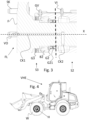
- Figure 3 shows an enlargement of the end portion of the hub.
- the two portions of the duct CK are visible, the first axial CK1 and the second axial or oblique CK2.
- Figure 3 also shows the opening GV necessary to fill chamber S3 with grease.
- the present invention also relates to an agricultural or work vehicle VHE, as shown in figure 4 , equipped with an axle formed by an opposing pair of hubs according to what is described above.
Landscapes
- Engineering & Computer Science (AREA)
- Mechanical Engineering (AREA)
- Rolling Contact Bearings (AREA)
- Steering-Linkage Mechanisms And Four-Wheel Steering (AREA)
- Tires In General (AREA)
Claims (7)
- Radnabe (H) für ein landwirtschaftliches Fahrzeug oder ein Arbeitsfahrzeug mit einer feststehenden Glocke (BL), die eine Längsachse (X) definiert, in der eine Radachse (SH) koaxial in einer drehbaren Weise angeordnet ist, die mittels eines Flansches (FL) außen angrenzend an die Glocke angeordnet ist, um mit einem entsprechenden Fahrzeugrad gekoppelt zu sein, wobei im Inneren der Nabe auf eine erste Kammer (S1) zur Aufnahme von Öl folgend eine zweite trockene Kammer (S2) und eine dritte Klammer (S3) zur Aufnahme von Schmierfett definiert sind, wobei die Glocke eine Durchgangsöffnung (VI) an der zweiten Kammer (S2) aufweist, und wobei die Radachse (SH) einen Durchgangskanal (CK) zwischen dem Flansch (FL) und der zweiten Kammer aufweist, um die erste Öffnung mit einem Druckverstellkreislauf und den Durchgangskanal mit einem entsprechendem Fahrzeugrad zu verbinden, wobei die zweite Kammer durch ein Paar von Druckdichtungen (G11, G21) axial begrenzt ist, wobei die Nabe (H) dadurch gekennzeichnet ist, dass eine erste Dichtung des Paars von Dichtungen (G11, G21) neben einer Schmierfett abdichtenden Dichtung (G2) angeordnet ist und eine zweite Dichtung des Paars von Dichtungen (G11, G21) neben einer Öldichtung (G1) angeordnet ist.
- Nabe nach Anspruch 1, wobei die dritte Kammer an dem freien Ende (FE) der Nabe angeordnet ist, wenn diese sich in einem Betriebszustand befindet.
- Nabe nach Anspruch 1 oder 2, wobei in der ersten und in der dritten Kammer jeweils ein inneres Lager (B1) und ein äußeres Lager (B2) angeordnet sind, um die Radachse innerhalb der Glocke zu lagern.
- Nabe nach einem der vorhergehenden Ansprüche, wobei der Durchgangskanal (CK) eine Öffnung in einer Stirnfläche (F) des Flansches aufweist, die dem zugehörigen Rad zugewandt ist.
- Nabe nach einem der vorhergehenden Ansprüche, wobei der Durchgangskanal einen ersten Abschnitt (CK1), der axial, parallel oder koaxial zu der Längsachse (X) der Radnabe (H) ist, und einen zweiten radialen oder schrägen Abschnitt (CK2) aufweist, der sich zwischen dem ersten Abschnitt des Durchgangskanals und der zweiten Kammer erstreckt.
- Fahrzeugachse mit einem Paar gegenüberliegenden Naben (H), wobei diese zentral eine Kammer in einem Ölbad definiert, in der jeweils die Naben nach einem der Ansprüche 1 bis 5 vorgesehen sind.
- Arbeitsfahrzeug oder landwirtschaftliches Fahrzeug (VHE) mit einem zentralen Befüllsystem, das eine Radnabe nach einem der Ansprüche 1 bis 5 umfasst.
Applications Claiming Priority (1)
| Application Number | Priority Date | Filing Date | Title |
|---|---|---|---|
| IT102020000024172A IT202000024172A1 (it) | 2020-10-14 | 2020-10-14 | Mozzo ruota di un veicolo agricolo o da lavoro |
Publications (2)
| Publication Number | Publication Date |
|---|---|
| EP3985272A1 EP3985272A1 (de) | 2022-04-20 |
| EP3985272B1 true EP3985272B1 (de) | 2024-05-15 |
Family
ID=73793759
Family Applications (1)
| Application Number | Title | Priority Date | Filing Date |
|---|---|---|---|
| EP21202559.7A Active EP3985272B1 (de) | 2020-10-14 | 2021-10-14 | Radnabe für ein landwirtschafts- oder arbeitsfahrzeug |
Country Status (2)
| Country | Link |
|---|---|
| EP (1) | EP3985272B1 (de) |
| IT (1) | IT202000024172A1 (de) |
Families Citing this family (1)
| Publication number | Priority date | Publication date | Assignee | Title |
|---|---|---|---|---|
| IT202300015393A1 (it) * | 2023-07-21 | 2025-01-21 | Cnh Ind Italia Spa | Mozzo ruota di un veicolo agricolo o da lavoro e sistema di accumulo di olio idraulico comprendente il mozzo ruota |
Family Cites Families (9)
| Publication number | Priority date | Publication date | Assignee | Title |
|---|---|---|---|---|
| US1112596A (en) * | 1913-05-28 | 1914-10-06 | Louis Burggraf Jr | Means for tire inflation. |
| US7302979B2 (en) * | 2005-03-16 | 2007-12-04 | Dana Corporation | Vehicle tire inflation system and sensor and method of use |
| GB201021928D0 (en) * | 2010-12-23 | 2011-02-02 | Agco Internat Ltd | Tyre inflation |
| GB201118156D0 (en) * | 2011-10-21 | 2011-11-30 | Agco Int Gmbh | Rotatable shaft comprising fluid duct |
| US9511635B2 (en) * | 2014-07-10 | 2016-12-06 | Airgo Ip, Llc | Apparatus for delivering air through powered axle assemblies |
| EP3103662B1 (de) * | 2015-06-12 | 2020-08-05 | Dana Heavy Vehicle Systems Group, LLC | Drehverbindungs-luftsammlerring und damit hergestelltes reifenaufpumpsystem |
| WO2017040802A1 (en) * | 2015-09-04 | 2017-03-09 | Dana Heavy Vehicle Systems Group, Llc | Rotary joint assembly |
| US10556469B2 (en) * | 2015-09-17 | 2020-02-11 | Dana Heavy Vehicle Systems Group, Llc | Hub cap assembly and a wheel end assembly for a tire inflation system |
| FR3068300B1 (fr) * | 2017-06-30 | 2019-08-16 | Poclain Hydraulics Industrie | Appareil hydraulique ameliore comprenant une conduite pour la circulation d'air |
-
2020
- 2020-10-14 IT IT102020000024172A patent/IT202000024172A1/it unknown
-
2021
- 2021-10-14 EP EP21202559.7A patent/EP3985272B1/de active Active
Also Published As
| Publication number | Publication date |
|---|---|
| EP3985272A1 (de) | 2022-04-20 |
| IT202000024172A1 (it) | 2022-04-14 |
Similar Documents
| Publication | Publication Date | Title |
|---|---|---|
| EP3164273B1 (de) | Drehdichtung für eine zentrale reifenaufpumpanlage | |
| CN109398078B (zh) | 具有电动马达模块和齿轮减速模块的车桥组件 | |
| CN109398079B (zh) | 具有电动马达模块的车桥组件 | |
| US4091688A (en) | Easily assembled and disassembled planetary gear assembly | |
| CN109398056B (zh) | 具有电动马达模块和换档机构的车桥组件 | |
| US9409449B2 (en) | Spindle assembly for a tire inflation system | |
| US9163715B2 (en) | Clutched power transmitting device with filter element | |
| US10556469B2 (en) | Hub cap assembly and a wheel end assembly for a tire inflation system | |
| DE10064231A1 (de) | Reifenaufblasvorrichtung für eine Achsschenkel-Radendanordnung | |
| EP3985272B1 (de) | Radnabe für ein landwirtschafts- oder arbeitsfahrzeug | |
| US4091689A (en) | Planetary steering hub assembly | |
| US2219025A (en) | Differential mechanism | |
| US10675923B2 (en) | Pneumatic system for inflating a wheel, integrated to a driven axle | |
| US9989102B2 (en) | Vented gaiter | |
| US11226040B2 (en) | Rotary seal apparatus and arrangement of a rotary seal apparatus in an axle support system | |
| RU154956U1 (ru) | Колесный узел с устройством подвода воздуха к шине | |
| EP3193043B1 (de) | Verfahren zum auswechseln von zahnräder einer differenzialanordnung | |
| WO2011070387A1 (en) | Driven wheel assembly and automotive vehicle equipped with such an assembly | |
| US11885404B2 (en) | Differential housing for a differential unit of a vehicle | |
| CN104791463A (zh) | 用于变速箱或旋转机器的通气装置 | |
| CN108506337A (zh) | 车轮用轴承装置 | |
| US11448300B1 (en) | Sealed planetary differential | |
| JP4565851B2 (ja) | 車両用の減速装置 | |
| US2134007A (en) | Rear axle wheel and brake assembly |
Legal Events
| Date | Code | Title | Description |
|---|---|---|---|
| PUAI | Public reference made under article 153(3) epc to a published international application that has entered the european phase |
Free format text: ORIGINAL CODE: 0009012 |
|
| STAA | Information on the status of an ep patent application or granted ep patent |
Free format text: STATUS: THE APPLICATION HAS BEEN PUBLISHED |
|
| AK | Designated contracting states |
Kind code of ref document: A1 Designated state(s): AL AT BE BG CH CY CZ DE DK EE ES FI FR GB GR HR HU IE IS IT LI LT LU LV MC MK MT NL NO PL PT RO RS SE SI SK SM TR |
|
| STAA | Information on the status of an ep patent application or granted ep patent |
Free format text: STATUS: REQUEST FOR EXAMINATION WAS MADE |
|
| 17P | Request for examination filed |
Effective date: 20221020 |
|
| RBV | Designated contracting states (corrected) |
Designated state(s): AL AT BE BG CH CY CZ DE DK EE ES FI FR GB GR HR HU IE IS IT LI LT LU LV MC MK MT NL NO PL PT RO RS SE SI SK SM TR |
|
| RAP3 | Party data changed (applicant data changed or rights of an application transferred) |
Owner name: CNH INDUSTRIAL ITALIA S.P.A. |
|
| GRAP | Despatch of communication of intention to grant a patent |
Free format text: ORIGINAL CODE: EPIDOSNIGR1 |
|
| STAA | Information on the status of an ep patent application or granted ep patent |
Free format text: STATUS: GRANT OF PATENT IS INTENDED |
|
| INTG | Intention to grant announced |
Effective date: 20231214 |
|
| GRAS | Grant fee paid |
Free format text: ORIGINAL CODE: EPIDOSNIGR3 |
|
| GRAA | (expected) grant |
Free format text: ORIGINAL CODE: 0009210 |
|
| STAA | Information on the status of an ep patent application or granted ep patent |
Free format text: STATUS: THE PATENT HAS BEEN GRANTED |
|
| AK | Designated contracting states |
Kind code of ref document: B1 Designated state(s): AL AT BE BG CH CY CZ DE DK EE ES FI FR GB GR HR HU IE IS IT LI LT LU LV MC MK MT NL NO PL PT RO RS SE SI SK SM TR |
|
| REG | Reference to a national code |
Ref country code: CH Ref legal event code: EP |
|
| REG | Reference to a national code |
Ref country code: IE Ref legal event code: FG4D |
|
| REG | Reference to a national code |
Ref country code: DE Ref legal event code: R096 Ref document number: 602021013267 Country of ref document: DE |
|
| REG | Reference to a national code |
Ref country code: LT Ref legal event code: MG9D |
|
| REG | Reference to a national code |
Ref country code: NL Ref legal event code: MP Effective date: 20240515 |
|
| PG25 | Lapsed in a contracting state [announced via postgrant information from national office to epo] |
Ref country code: IS Free format text: LAPSE BECAUSE OF FAILURE TO SUBMIT A TRANSLATION OF THE DESCRIPTION OR TO PAY THE FEE WITHIN THE PRESCRIBED TIME-LIMIT Effective date: 20240915 |
|
| PG25 | Lapsed in a contracting state [announced via postgrant information from national office to epo] |
Ref country code: BG Free format text: LAPSE BECAUSE OF FAILURE TO SUBMIT A TRANSLATION OF THE DESCRIPTION OR TO PAY THE FEE WITHIN THE PRESCRIBED TIME-LIMIT Effective date: 20240515 |
|
| PG25 | Lapsed in a contracting state [announced via postgrant information from national office to epo] |
Ref country code: HR Free format text: LAPSE BECAUSE OF FAILURE TO SUBMIT A TRANSLATION OF THE DESCRIPTION OR TO PAY THE FEE WITHIN THE PRESCRIBED TIME-LIMIT Effective date: 20240515 Ref country code: FI Free format text: LAPSE BECAUSE OF FAILURE TO SUBMIT A TRANSLATION OF THE DESCRIPTION OR TO PAY THE FEE WITHIN THE PRESCRIBED TIME-LIMIT Effective date: 20240515 |
|
| PG25 | Lapsed in a contracting state [announced via postgrant information from national office to epo] |
Ref country code: GR Free format text: LAPSE BECAUSE OF FAILURE TO SUBMIT A TRANSLATION OF THE DESCRIPTION OR TO PAY THE FEE WITHIN THE PRESCRIBED TIME-LIMIT Effective date: 20240816 |
|
| PG25 | Lapsed in a contracting state [announced via postgrant information from national office to epo] |
Ref country code: PT Free format text: LAPSE BECAUSE OF FAILURE TO SUBMIT A TRANSLATION OF THE DESCRIPTION OR TO PAY THE FEE WITHIN THE PRESCRIBED TIME-LIMIT Effective date: 20240916 |
|
| REG | Reference to a national code |
Ref country code: AT Ref legal event code: MK05 Ref document number: 1687136 Country of ref document: AT Kind code of ref document: T Effective date: 20240515 |
|
| PG25 | Lapsed in a contracting state [announced via postgrant information from national office to epo] |
Ref country code: NL Free format text: LAPSE BECAUSE OF FAILURE TO SUBMIT A TRANSLATION OF THE DESCRIPTION OR TO PAY THE FEE WITHIN THE PRESCRIBED TIME-LIMIT Effective date: 20240515 |
|
| PG25 | Lapsed in a contracting state [announced via postgrant information from national office to epo] |
Ref country code: ES Free format text: LAPSE BECAUSE OF FAILURE TO SUBMIT A TRANSLATION OF THE DESCRIPTION OR TO PAY THE FEE WITHIN THE PRESCRIBED TIME-LIMIT Effective date: 20240515 |
|
| PG25 | Lapsed in a contracting state [announced via postgrant information from national office to epo] |
Ref country code: AT Free format text: LAPSE BECAUSE OF FAILURE TO SUBMIT A TRANSLATION OF THE DESCRIPTION OR TO PAY THE FEE WITHIN THE PRESCRIBED TIME-LIMIT Effective date: 20240515 |
|
| PG25 | Lapsed in a contracting state [announced via postgrant information from national office to epo] |
Ref country code: PL Free format text: LAPSE BECAUSE OF FAILURE TO SUBMIT A TRANSLATION OF THE DESCRIPTION OR TO PAY THE FEE WITHIN THE PRESCRIBED TIME-LIMIT Effective date: 20240515 |
|
| PG25 | Lapsed in a contracting state [announced via postgrant information from national office to epo] |
Ref country code: LV Free format text: LAPSE BECAUSE OF FAILURE TO SUBMIT A TRANSLATION OF THE DESCRIPTION OR TO PAY THE FEE WITHIN THE PRESCRIBED TIME-LIMIT Effective date: 20240515 |
|
| PG25 | Lapsed in a contracting state [announced via postgrant information from national office to epo] |
Ref country code: PT Free format text: LAPSE BECAUSE OF FAILURE TO SUBMIT A TRANSLATION OF THE DESCRIPTION OR TO PAY THE FEE WITHIN THE PRESCRIBED TIME-LIMIT Effective date: 20240916 Ref country code: PL Free format text: LAPSE BECAUSE OF FAILURE TO SUBMIT A TRANSLATION OF THE DESCRIPTION OR TO PAY THE FEE WITHIN THE PRESCRIBED TIME-LIMIT Effective date: 20240515 Ref country code: NO Free format text: LAPSE BECAUSE OF FAILURE TO SUBMIT A TRANSLATION OF THE DESCRIPTION OR TO PAY THE FEE WITHIN THE PRESCRIBED TIME-LIMIT Effective date: 20240815 Ref country code: NL Free format text: LAPSE BECAUSE OF FAILURE TO SUBMIT A TRANSLATION OF THE DESCRIPTION OR TO PAY THE FEE WITHIN THE PRESCRIBED TIME-LIMIT Effective date: 20240515 Ref country code: LV Free format text: LAPSE BECAUSE OF FAILURE TO SUBMIT A TRANSLATION OF THE DESCRIPTION OR TO PAY THE FEE WITHIN THE PRESCRIBED TIME-LIMIT Effective date: 20240515 Ref country code: IS Free format text: LAPSE BECAUSE OF FAILURE TO SUBMIT A TRANSLATION OF THE DESCRIPTION OR TO PAY THE FEE WITHIN THE PRESCRIBED TIME-LIMIT Effective date: 20240915 Ref country code: HR Free format text: LAPSE BECAUSE OF FAILURE TO SUBMIT A TRANSLATION OF THE DESCRIPTION OR TO PAY THE FEE WITHIN THE PRESCRIBED TIME-LIMIT Effective date: 20240515 Ref country code: GR Free format text: LAPSE BECAUSE OF FAILURE TO SUBMIT A TRANSLATION OF THE DESCRIPTION OR TO PAY THE FEE WITHIN THE PRESCRIBED TIME-LIMIT Effective date: 20240816 Ref country code: FI Free format text: LAPSE BECAUSE OF FAILURE TO SUBMIT A TRANSLATION OF THE DESCRIPTION OR TO PAY THE FEE WITHIN THE PRESCRIBED TIME-LIMIT Effective date: 20240515 Ref country code: ES Free format text: LAPSE BECAUSE OF FAILURE TO SUBMIT A TRANSLATION OF THE DESCRIPTION OR TO PAY THE FEE WITHIN THE PRESCRIBED TIME-LIMIT Effective date: 20240515 Ref country code: BG Free format text: LAPSE BECAUSE OF FAILURE TO SUBMIT A TRANSLATION OF THE DESCRIPTION OR TO PAY THE FEE WITHIN THE PRESCRIBED TIME-LIMIT Effective date: 20240515 Ref country code: AT Free format text: LAPSE BECAUSE OF FAILURE TO SUBMIT A TRANSLATION OF THE DESCRIPTION OR TO PAY THE FEE WITHIN THE PRESCRIBED TIME-LIMIT Effective date: 20240515 Ref country code: RS Free format text: LAPSE BECAUSE OF FAILURE TO SUBMIT A TRANSLATION OF THE DESCRIPTION OR TO PAY THE FEE WITHIN THE PRESCRIBED TIME-LIMIT Effective date: 20240815 |
|
| PG25 | Lapsed in a contracting state [announced via postgrant information from national office to epo] |
Ref country code: DK Free format text: LAPSE BECAUSE OF FAILURE TO SUBMIT A TRANSLATION OF THE DESCRIPTION OR TO PAY THE FEE WITHIN THE PRESCRIBED TIME-LIMIT Effective date: 20240515 |
|
| PG25 | Lapsed in a contracting state [announced via postgrant information from national office to epo] |
Ref country code: EE Free format text: LAPSE BECAUSE OF FAILURE TO SUBMIT A TRANSLATION OF THE DESCRIPTION OR TO PAY THE FEE WITHIN THE PRESCRIBED TIME-LIMIT Effective date: 20240515 |
|
| PG25 | Lapsed in a contracting state [announced via postgrant information from national office to epo] |
Ref country code: CZ Free format text: LAPSE BECAUSE OF FAILURE TO SUBMIT A TRANSLATION OF THE DESCRIPTION OR TO PAY THE FEE WITHIN THE PRESCRIBED TIME-LIMIT Effective date: 20240515 |
|
| PG25 | Lapsed in a contracting state [announced via postgrant information from national office to epo] |
Ref country code: SK Free format text: LAPSE BECAUSE OF FAILURE TO SUBMIT A TRANSLATION OF THE DESCRIPTION OR TO PAY THE FEE WITHIN THE PRESCRIBED TIME-LIMIT Effective date: 20240515 Ref country code: RO Free format text: LAPSE BECAUSE OF FAILURE TO SUBMIT A TRANSLATION OF THE DESCRIPTION OR TO PAY THE FEE WITHIN THE PRESCRIBED TIME-LIMIT Effective date: 20240515 |
|
| PG25 | Lapsed in a contracting state [announced via postgrant information from national office to epo] |
Ref country code: SM Free format text: LAPSE BECAUSE OF FAILURE TO SUBMIT A TRANSLATION OF THE DESCRIPTION OR TO PAY THE FEE WITHIN THE PRESCRIBED TIME-LIMIT Effective date: 20240515 |
|
| PG25 | Lapsed in a contracting state [announced via postgrant information from national office to epo] |
Ref country code: SM Free format text: LAPSE BECAUSE OF FAILURE TO SUBMIT A TRANSLATION OF THE DESCRIPTION OR TO PAY THE FEE WITHIN THE PRESCRIBED TIME-LIMIT Effective date: 20240515 Ref country code: SK Free format text: LAPSE BECAUSE OF FAILURE TO SUBMIT A TRANSLATION OF THE DESCRIPTION OR TO PAY THE FEE WITHIN THE PRESCRIBED TIME-LIMIT Effective date: 20240515 Ref country code: RO Free format text: LAPSE BECAUSE OF FAILURE TO SUBMIT A TRANSLATION OF THE DESCRIPTION OR TO PAY THE FEE WITHIN THE PRESCRIBED TIME-LIMIT Effective date: 20240515 Ref country code: EE Free format text: LAPSE BECAUSE OF FAILURE TO SUBMIT A TRANSLATION OF THE DESCRIPTION OR TO PAY THE FEE WITHIN THE PRESCRIBED TIME-LIMIT Effective date: 20240515 Ref country code: DK Free format text: LAPSE BECAUSE OF FAILURE TO SUBMIT A TRANSLATION OF THE DESCRIPTION OR TO PAY THE FEE WITHIN THE PRESCRIBED TIME-LIMIT Effective date: 20240515 Ref country code: CZ Free format text: LAPSE BECAUSE OF FAILURE TO SUBMIT A TRANSLATION OF THE DESCRIPTION OR TO PAY THE FEE WITHIN THE PRESCRIBED TIME-LIMIT Effective date: 20240515 |
|
| REG | Reference to a national code |
Ref country code: DE Ref legal event code: R097 Ref document number: 602021013267 Country of ref document: DE |
|
| PLBE | No opposition filed within time limit |
Free format text: ORIGINAL CODE: 0009261 |
|
| STAA | Information on the status of an ep patent application or granted ep patent |
Free format text: STATUS: NO OPPOSITION FILED WITHIN TIME LIMIT |
|
| 26N | No opposition filed |
Effective date: 20250218 |
|
| PG25 | Lapsed in a contracting state [announced via postgrant information from national office to epo] |
Ref country code: SI Free format text: LAPSE BECAUSE OF FAILURE TO SUBMIT A TRANSLATION OF THE DESCRIPTION OR TO PAY THE FEE WITHIN THE PRESCRIBED TIME-LIMIT Effective date: 20240515 |
|
| REG | Reference to a national code |
Ref country code: CH Ref legal event code: PL |
|
| PG25 | Lapsed in a contracting state [announced via postgrant information from national office to epo] |
Ref country code: MC Free format text: LAPSE BECAUSE OF FAILURE TO SUBMIT A TRANSLATION OF THE DESCRIPTION OR TO PAY THE FEE WITHIN THE PRESCRIBED TIME-LIMIT Effective date: 20240515 |
|
| PG25 | Lapsed in a contracting state [announced via postgrant information from national office to epo] |
Ref country code: LU Free format text: LAPSE BECAUSE OF NON-PAYMENT OF DUE FEES Effective date: 20241014 Ref country code: BE Free format text: LAPSE BECAUSE OF NON-PAYMENT OF DUE FEES Effective date: 20241031 |
|
| PG25 | Lapsed in a contracting state [announced via postgrant information from national office to epo] |
Ref country code: CH Free format text: LAPSE BECAUSE OF NON-PAYMENT OF DUE FEES Effective date: 20241031 |
|
| REG | Reference to a national code |
Ref country code: BE Ref legal event code: MM Effective date: 20241031 |
|
| PG25 | Lapsed in a contracting state [announced via postgrant information from national office to epo] |
Ref country code: SE Free format text: LAPSE BECAUSE OF FAILURE TO SUBMIT A TRANSLATION OF THE DESCRIPTION OR TO PAY THE FEE WITHIN THE PRESCRIBED TIME-LIMIT Effective date: 20240515 |
|
| PG25 | Lapsed in a contracting state [announced via postgrant information from national office to epo] |
Ref country code: IE Free format text: LAPSE BECAUSE OF NON-PAYMENT OF DUE FEES Effective date: 20241014 |
|
| PGFP | Annual fee paid to national office [announced via postgrant information from national office to epo] |
Ref country code: DE Payment date: 20251028 Year of fee payment: 5 |
|
| PGFP | Annual fee paid to national office [announced via postgrant information from national office to epo] |
Ref country code: GB Payment date: 20251021 Year of fee payment: 5 |
|
| PGFP | Annual fee paid to national office [announced via postgrant information from national office to epo] |
Ref country code: IT Payment date: 20251024 Year of fee payment: 5 |
|
| PGFP | Annual fee paid to national office [announced via postgrant information from national office to epo] |
Ref country code: FR Payment date: 20251027 Year of fee payment: 5 |
|
| PG25 | Lapsed in a contracting state [announced via postgrant information from national office to epo] |
Ref country code: CY Free format text: LAPSE BECAUSE OF FAILURE TO SUBMIT A TRANSLATION OF THE DESCRIPTION OR TO PAY THE FEE WITHIN THE PRESCRIBED TIME-LIMIT; INVALID AB INITIO Effective date: 20211014 |
|
| PG25 | Lapsed in a contracting state [announced via postgrant information from national office to epo] |
Ref country code: HU Free format text: LAPSE BECAUSE OF FAILURE TO SUBMIT A TRANSLATION OF THE DESCRIPTION OR TO PAY THE FEE WITHIN THE PRESCRIBED TIME-LIMIT; INVALID AB INITIO Effective date: 20211014 |