EP3995380A1 - Structure permettant de changer un agencement de siège d'habitacle - Google Patents
Structure permettant de changer un agencement de siège d'habitacle Download PDFInfo
- Publication number
- EP3995380A1 EP3995380A1 EP20834472.1A EP20834472A EP3995380A1 EP 3995380 A1 EP3995380 A1 EP 3995380A1 EP 20834472 A EP20834472 A EP 20834472A EP 3995380 A1 EP3995380 A1 EP 3995380A1
- Authority
- EP
- European Patent Office
- Prior art keywords
- seats
- guide rail
- support
- vehicle
- seat
- Prior art date
- Legal status (The legal status is an assumption and is not a legal conclusion. Google has not performed a legal analysis and makes no representation as to the accuracy of the status listed.)
- Granted
Links
Images


Classifications
-
- B—PERFORMING OPERATIONS; TRANSPORTING
- B60—VEHICLES IN GENERAL
- B60N—SEATS SPECIALLY ADAPTED FOR VEHICLES; VEHICLE PASSENGER ACCOMMODATION NOT OTHERWISE PROVIDED FOR
- B60N2/00—Seats specially adapted for vehicles; Arrangement or mounting of seats in vehicles
- B60N2/02—Seats specially adapted for vehicles; Arrangement or mounting of seats in vehicles the seat or part thereof being movable, e.g. adjustable
- B60N2/04—Seats specially adapted for vehicles; Arrangement or mounting of seats in vehicles the seat or part thereof being movable, e.g. adjustable the whole seat being movable
- B60N2/06—Seats specially adapted for vehicles; Arrangement or mounting of seats in vehicles the seat or part thereof being movable, e.g. adjustable the whole seat being movable slidable
-
- B—PERFORMING OPERATIONS; TRANSPORTING
- B64—AIRCRAFT; AVIATION; COSMONAUTICS
- B64D—EQUIPMENT FOR FITTING IN OR TO AIRCRAFT; FLIGHT SUITS; PARACHUTES; ARRANGEMENT OR MOUNTING OF POWER PLANTS OR PROPULSION TRANSMISSIONS IN AIRCRAFT
- B64D11/00—Passenger or crew accommodation; Flight-deck installations not otherwise provided for
- B64D11/06—Arrangements of seats, or adaptations or details specially adapted for aircraft seats
- B64D11/0648—Lower frame constructions
-
- B—PERFORMING OPERATIONS; TRANSPORTING
- B60—VEHICLES IN GENERAL
- B60N—SEATS SPECIALLY ADAPTED FOR VEHICLES; VEHICLE PASSENGER ACCOMMODATION NOT OTHERWISE PROVIDED FOR
- B60N2/00—Seats specially adapted for vehicles; Arrangement or mounting of seats in vehicles
- B60N2/005—Arrangement or mounting of seats in vehicles, e.g. dismountable auxiliary seats
- B60N2/01—Arrangement of seats relative to one another
-
- B—PERFORMING OPERATIONS; TRANSPORTING
- B60—VEHICLES IN GENERAL
- B60N—SEATS SPECIALLY ADAPTED FOR VEHICLES; VEHICLE PASSENGER ACCOMMODATION NOT OTHERWISE PROVIDED FOR
- B60N2/00—Seats specially adapted for vehicles; Arrangement or mounting of seats in vehicles
- B60N2/02—Seats specially adapted for vehicles; Arrangement or mounting of seats in vehicles the seat or part thereof being movable, e.g. adjustable
- B60N2/04—Seats specially adapted for vehicles; Arrangement or mounting of seats in vehicles the seat or part thereof being movable, e.g. adjustable the whole seat being movable
- B60N2/06—Seats specially adapted for vehicles; Arrangement or mounting of seats in vehicles the seat or part thereof being movable, e.g. adjustable the whole seat being movable slidable
- B60N2/062—Seats specially adapted for vehicles; Arrangement or mounting of seats in vehicles the seat or part thereof being movable, e.g. adjustable the whole seat being movable slidable transversally slidable
-
- B—PERFORMING OPERATIONS; TRANSPORTING
- B60—VEHICLES IN GENERAL
- B60N—SEATS SPECIALLY ADAPTED FOR VEHICLES; VEHICLE PASSENGER ACCOMMODATION NOT OTHERWISE PROVIDED FOR
- B60N2/00—Seats specially adapted for vehicles; Arrangement or mounting of seats in vehicles
- B60N2/02—Seats specially adapted for vehicles; Arrangement or mounting of seats in vehicles the seat or part thereof being movable, e.g. adjustable
- B60N2/04—Seats specially adapted for vehicles; Arrangement or mounting of seats in vehicles the seat or part thereof being movable, e.g. adjustable the whole seat being movable
- B60N2/06—Seats specially adapted for vehicles; Arrangement or mounting of seats in vehicles the seat or part thereof being movable, e.g. adjustable the whole seat being movable slidable
- B60N2/07—Slide construction
- B60N2/0702—Slide construction characterised by its cross-section
- B60N2/0715—C or U-shaped
-
- B—PERFORMING OPERATIONS; TRANSPORTING
- B60—VEHICLES IN GENERAL
- B60N—SEATS SPECIALLY ADAPTED FOR VEHICLES; VEHICLE PASSENGER ACCOMMODATION NOT OTHERWISE PROVIDED FOR
- B60N2/00—Seats specially adapted for vehicles; Arrangement or mounting of seats in vehicles
- B60N2/02—Seats specially adapted for vehicles; Arrangement or mounting of seats in vehicles the seat or part thereof being movable, e.g. adjustable
- B60N2/04—Seats specially adapted for vehicles; Arrangement or mounting of seats in vehicles the seat or part thereof being movable, e.g. adjustable the whole seat being movable
- B60N2/06—Seats specially adapted for vehicles; Arrangement or mounting of seats in vehicles the seat or part thereof being movable, e.g. adjustable the whole seat being movable slidable
- B60N2/07—Slide construction
- B60N2/0735—Position and orientation of the slide as a whole
- B60N2/0747—Position and orientation of the slide as a whole the opening of the cross section being oriented in a direction different from the vertical, e.g. transversal
-
- B—PERFORMING OPERATIONS; TRANSPORTING
- B60—VEHICLES IN GENERAL
- B60N—SEATS SPECIALLY ADAPTED FOR VEHICLES; VEHICLE PASSENGER ACCOMMODATION NOT OTHERWISE PROVIDED FOR
- B60N2/00—Seats specially adapted for vehicles; Arrangement or mounting of seats in vehicles
- B60N2/02—Seats specially adapted for vehicles; Arrangement or mounting of seats in vehicles the seat or part thereof being movable, e.g. adjustable
- B60N2/04—Seats specially adapted for vehicles; Arrangement or mounting of seats in vehicles the seat or part thereof being movable, e.g. adjustable the whole seat being movable
- B60N2/14—Seats specially adapted for vehicles; Arrangement or mounting of seats in vehicles the seat or part thereof being movable, e.g. adjustable the whole seat being movable rotatable, e.g. to permit easy access
-
- B—PERFORMING OPERATIONS; TRANSPORTING
- B60—VEHICLES IN GENERAL
- B60N—SEATS SPECIALLY ADAPTED FOR VEHICLES; VEHICLE PASSENGER ACCOMMODATION NOT OTHERWISE PROVIDED FOR
- B60N2/00—Seats specially adapted for vehicles; Arrangement or mounting of seats in vehicles
- B60N2/24—Seats specially adapted for vehicles; Arrangement or mounting of seats in vehicles for particular purposes or particular vehicles
- B60N2/242—Bus seats
-
- B—PERFORMING OPERATIONS; TRANSPORTING
- B61—RAILWAYS
- B61D—BODY DETAILS OR KINDS OF RAILWAY VEHICLES
- B61D1/00—Carriages for ordinary railway passenger traffic
- B61D1/04—General arrangements of seats
-
- B—PERFORMING OPERATIONS; TRANSPORTING
- B61—RAILWAYS
- B61D—BODY DETAILS OR KINDS OF RAILWAY VEHICLES
- B61D33/00—Seats
-
- B—PERFORMING OPERATIONS; TRANSPORTING
- B61—RAILWAYS
- B61D—BODY DETAILS OR KINDS OF RAILWAY VEHICLES
- B61D33/00—Seats
- B61D33/0057—Seats characterised by their mounting in vehicles
- B61D33/0078—Seats characterised by their mounting in vehicles adjustably mounted
- B61D33/0085—Seats characterised by their mounting in vehicles adjustably mounted rotatably
-
- B—PERFORMING OPERATIONS; TRANSPORTING
- B64—AIRCRAFT; AVIATION; COSMONAUTICS
- B64D—EQUIPMENT FOR FITTING IN OR TO AIRCRAFT; FLIGHT SUITS; PARACHUTES; ARRANGEMENT OR MOUNTING OF POWER PLANTS OR PROPULSION TRANSMISSIONS IN AIRCRAFT
- B64D11/00—Passenger or crew accommodation; Flight-deck installations not otherwise provided for
- B64D11/06—Arrangements of seats, or adaptations or details specially adapted for aircraft seats
- B64D11/0639—Arrangements of seats, or adaptations or details specially adapted for aircraft seats with features for adjustment or converting of seats
Definitions
- the present invention relates to a structure for freely changing an arrangement interval of seats provided in a vehicle cabin of a railway vehicle, a bus, or the like.
- passenger seats are generally arranged along a side wall of a vehicle cabin.
- a space in the middle of the vehicle cabin is used as a standing space or an aisle space.
- a so-called long arrangement and a so-called cross arrangement are common.
- the seats are arranged in such a manner that backrest surfaces thereof are substantially parallel to a traveling direction of the vehicle.
- the seats are arranged in such a manner that the backrest surfaces thereof are oriented in the traveling direction of the vehicle or a direction opposite to the traveling direction.
- the seats are arranged on a floor plate of the vehicle cabin at a regular interval.
- the comfort of the passenger who is seated is superior as an arrangement interval of the seats is larger.
- the arrangement pitch of the seats is large, a standing space or an aisle space is narrowed, with the result that the comfort of a passenger who cannot be seated is impaired.
- the arrangement of the seats in the vehicle cabin can be flexibly changed in accordance with an increase or decrease of the number of passengers such as a peak season or a low season.
- the space in the vehicle cabin can be flexibly used, which is convenient.
- Patent Literature 1 discloses a structure for freely changing an arrangement interval of seats in a vehicle cabin of an aircraft.
- a rail is laid on a floor plate of the vehicle cabin, and the seats can be freely moved along the rail in the vehicle cabin and can be fixed at a suitable position on the rail.
- the arrangement interval of the seats in the vehicle cabin can be freely changed, and the limited space in the vehicle cabin can be flexibly used in accordance with the number of passengers, thereby being capable of improving the comfort of the passenger.
- the present invention has been made to solve the problems described above, and has an object to provide a changing structure for a seat arrangement, which is capable of freely adjusting an arrangement interval of seats in a vehicle cabin and effectively utilizing a space below the seats.
- a changing structure for a seat arrangement for freely changing an arrangement interval of seats in a vehicle cabin of a vehicle including: a support frame configured to support the seats from below as a cantilever beam to define a space between the seats and a floor plate of the vehicle; a guide rail provided along a side structure of the vehicle along a longitudinal direction of the vehicle cabin; a support slider, which is fixed to a base end portion of the support frame and is assembled to the guide rail, and is freely movable along the guide rail while bearing a load and a rotation moment acting from the support frame; and a position fixing member configured to fix the support slider to the guide rail.
- the support frame that supports the seats can be freely moved along the guide rail due to the movement of the support slider, thereby being capable of freely adjusting the arrangement interval of the seats in the vehicle cabin.
- the support frame supports the seats from below as the cantilever beam, and meanwhile, the support slider fixed to the base end portion of the support frame bears a load and a rotation moment acting from the support frame while freely moving along the guide rail.
- legs or the like are not required to be provided between the seats and the floor plate, thereby being capable of effectively using the space below the seats.
- FIG. 1 is a view for illustrating a first embodiment in which the present invention is applied to an arrangement of seats 2 in a vehicle cabin 1 of a railway vehicle.
- FIG. 1 is an illustration of a state in which a roof structure is removed from the vehicle and the vehicle cabin 1 is cut in the middle of the vehicle cabin 1 in a width direction thereof.
- the arrangement of the seats 2 is a so-called cross arrangement, and each of the seats 2 is arranged in the vehicle cabin 1 under a state in which a backrest surface 20 is oriented in a traveling direction A of the vehicle or a direction opposite to the traveling direction.
- the seats 2 are not provided on a floor plate 10 of the vehicle but are each supported by a support frame 3 projecting from a side structure 11 of the vehicle. Further, in order that an arrangement interval of the seats 2 in the vehicle cabin 1 can be freely changed, the support frames 3 are each mounted to the side structure 11 of the vehicle using a position changing mechanism 4.
- FIG. 2 is a view for schematically illustrating a support structure for the seats 2 with respect to the side structure 11.
- the seats 2 are mounted to the support frame 3, and the support frame 3 is fixed to the side structure 11 of the vehicle through intermediation of the position changing mechanism 4, and supports the seats 2 from below as a cantilever beam.
- the position changing mechanism 4 includes a guide rail 40 fixed to the side structure 11, and a support slider 41 assembled to the guide rail 40.
- the guide rail 40 is provided in parallel to the floor plate 10 and along a longitudinal direction of the vehicle cabin 1, and the support slider 41 can be freely moved along the guide rail 40. Further, the support slider 41 is fixed to a base end portion of the support frame 3 being the cantilever beam.
- FIG. 3 and FIG. 4 are illustrations of an example of the position changing mechanism 4.
- FIG. 3 is a perspective view of the position changing mechanism 4
- FIG. 4 is a sectional view taken along the line IV-IV of FIG. 3 .
- the position changing mechanism 4 includes the guide rail 40 and the support slider 41.
- the guide rail 40 is an elongated member having a substantially rectangular shape in a cross section perpendicular to the longitudinal direction, and has rolling grooves 44 for balls, which are formed in outer surfaces along the longitudinal direction.
- the support slider 41 is assembled to the guide rail 40 through intermediation of a large number of balls 45 that roll on the rolling grooves.
- the rolling grooves 44 are formed in a pair on right and left sides of the guide rail 40.
- the rolling grooves 44 are each formed in a concave curved surface shape with an arc slightly larger than a spherical surface of the ball 45, and a depth of the rolling groove 44 with respect to the outer surface of the guide rail 40 is set slightly smaller than a radius of the ball 45.
- the outer surfaces of the guide rail 40 have locking grooves 46 formed in parallel to the rolling grooves 44.
- the locking grooves 46 are located below the rolling grooves 44, and the guide rail 40 has a substantially trapezoidal shape gradually narrowed toward the center of the guide rail 40 in a cross section perpendicular to the longitudinal direction. Further, a depth of the locking groove 46 is set larger than that of the rolling groove 44.
- the locking grooves 46 are formed in a pair on right and left sides of the guide rail 40.
- the guide rail 40 has a plurality of fixing holes 47 and a plurality of positioning holes 48 which are formed alternately at predetermined intervals along the longitudinal direction.
- the fixing holes 47 are used for fixing the guide rail 40 to a structure such as the side structure 11 with bolts.
- the positioning holes 48 are used for immovably fixing the support slider 41 at a specific position on the guide rail 40, and a locking pin 49 provided to the support slider 41 is inserted to the positioning hole 48 as appropriate.
- the support slider 41 includes a block main body 42 formed in a substantially saddle shape so as to straddle the guide rail 40, a pair of lid members 43 mounted to both front and rear end surfaces of the block main body 42 in a moving direction thereof, and the locking pin 49 passing through the block main body 42.
- the block main body 42 includes a base portion 42a having fastening holes 50 for fixing bolts, and a pair of skirt portions 42b hanging from the base portion 42a so as to cover the outer surfaces of the guide rail 40.
- the skirt portions 42b each have a load rolling groove 51 opposed to the rolling groove 44 of the guide rail 40, and the balls 45 roll while applying a load between the load rolling groove 51 of the block main body 42 and the rolling groove 44 of the guide rail 40.
- the skirt portion 42b has a ball return hole 52 formed in parallel to the load rolling groove 51, and the balls 45 roll inside the ball return hole 52 in a no-load state.
- Each of the pair of lid members 43 has direction change paths in which the balls 45 roll in a no-load state.
- the direction change path is a path curved in a substantially U-shaped, and when the lid member 43 is fixed to the block main body 42, longitudinal end portions of the load rolling groove 51 and the ball return hole 52 formed in the block main body 42 are coupled to each other by the direction change path. That is, when the lid members 43 are fixed to both end surfaces of the block main body 42, respectively, each of the load rolling grooves 51 and each of the ball return holes 52 are coupled to each other, thereby completing endless circulation paths for the balls 45 in the support slider 41.
- the support slider 41 includes two endless circulation paths for the balls 45 corresponding to the pair of rolling grooves 44 formed in the guide rail 40.
- the skirt portion 42b of the block main body 42 has a support protruding portion 53 in parallel to the load rolling groove 51.
- the support protruding portion 53 protrudes from an inner surface of the skirt portion 42b toward the guide rail 40, and is inserted into the locking groove 46 formed in the outer surface of the guide rail 40.
- a gap is defined between the support protruding portion 53 and the locking groove 46.
- the support protruding portion 53 does not come in contact with the guide rail 40 unless an excessive load acts on the support slider 41, and the support slider 41 can smoothly move on the guide rail 40 by rolling of the balls 45.
- the rolling grooves 44 for the balls 45 are formed in the pair of outer surfaces of the guide rail 40, and the support slider 41 is assembled to the guide rail 40 through intermediation of the balls 45 that roll on the rolling grooves 44.
- the support slider 41 can be freely moved along the guide rail 40 while bearing any load acting in a direction orthogonal to a longitudinal direction of the guide rail 40.
- the support slider 41 under the state in which the support slider 41 is assembled to the guide rail 40, the support protruding portions 53 of the block main body 42 are inserted into the locking grooves 46 of the guide rail 40. Thus, the support slider 41 cannot be separated from the guide rail 40 in the direction orthogonal to the longitudinal direction of the guide rail 40. Accordingly, even when an excessive moment load (load in the arrow R direction of FIG. 4 ) acts on the support slider 41 fixed to the support frame 3, for example, in accordance with the weight of a passenger seated on the seats 2, due to the contact between the support protruding portions 53 and the locking grooves 46, the assembled state of the support slider 41 with respect to the guide rail 40 is maintained, thereby being capable of holding the support frame 3 against the moment load.
- an excessive moment load load in the arrow R direction of FIG. 4
- the locking pin 49 is provided to the support slider 41, and the locking pin 49 passes through the support slider 41 to be inserted into the positioning hole 48 of the guide rail 40.
- the locking pin 49 is held by the support slider 41 under a state in which the locking pin 49 is urged toward the guide rail 40, and under a state in which no external force is applied to the locking pin 49, a distal end portion of the locking pin 49 is always inserted into the positioning hole 48 of the guide rail 40.
- the support slider 41 Under the state in which the locking pin 49 is inserted into the positioning hole 48, the support slider 41 cannot be moved with respect to the guide rail 40, and only when the locking pin 49 is removed from the positioning hole 48 against the urging force, the support slider 41 can be moved along the guide rail 40. That is, the locking pin 49 corresponds to a position fixing member in the present invention.
- the position fixing member is not limited to the locking pin 49 mounted to the support slider 41, and may be any member as long as the member can reliably restrain a motion of the support slider 41 with respect to the guide rail 40.
- the position fixing member may be a clamping member that is fixed to the guide rail 40 so as to sandwich the guide rail 40 and locks the motion of the support slider 41.
- the support slider 41 of the position changing mechanism 4 is fixed to the support frame 3 using the fastening holes 50.
- the guide rail 40 of the position changing mechanism 4 is fixed to the side structure 11 of the vehicle with bolts in a horizontal direction.
- side columns are provided upright inside the side structure 11 along a vertical direction (up-and-down direction of the drawing sheet of FIG. 2 ) for the purpose of securing the strength of the side structure 11.
- the plurality of side columns are arranged at predetermined intervals along a traveling direction of the vehicle (depth direction of the drawing sheet of FIG. 2 ).
- a rail mounting plate extending along the traveling direction of the vehicle is fixed to the plurality of those side columns, and the guide rail 40 is fixed to the rail mounting plate with bolts.
- a vertical load or a moment load acting on the guide rail 40 is born by the side columns through intermediation of the rail mounting plate.
- the structure of the side structure 11 described above is merely an example, and the fixing method for the guide rail can be appropriately changed in accordance with the concrete structure of the side structure.
- the support slider 41 of the position changing mechanism 4 when the support slider 41 of the position changing mechanism 4 is moved along the guide rail 40, the support frame 3 having the seats 2 mounted thereon is moved together with the seats 2 along the side structure 11, and the arrangement interval of the seats 2 in a so-called cross arrangement can be freely changed along the traveling direction of the vehicle. Further, through operation of the locking pin 49 provided to the support slider 41, movement or fixing of the support slider 41 with respect to the guide rail 40 can be freely selected, thereby being capable of readily changing the arrangement interval of the seats 2.
- the support slider 41 of the position changing mechanism 4 can be pulled out from the end portion of the guide rail 40 in the longitudinal direction.
- a seat mounting position at which the guide rail 40 is interrupted is provided at any position of the side structure 11 of the vehicle so that, at the position, the support slider 41 can be pulled out from the guide rail 40 or can be assembled to the guide rail 40. Accordingly, the seats 2 can be freely installed on or removed from the vehicle cabin 1.
- the arrangement interval of the seats 2 in the vehicle cabin 1 can be freely changed, and the arrangement of the seats 2 in the vehicle cabin 1 can be flexibly changed in accordance with an increase or decrease of the number of passengers such as a peak season or a low season.
- the support frame 3 supports the seats 2 from below as the cantilever beam.
- a space can be defined between the seats 2 and the floor plate 10, and the comfort of the vehicle cabin 1 can be enhanced by effectively utilizing the space.
- legs of the seats 2 are not connected to the floor surface, and hence the floor surface can be easily cleaned.
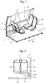
- FIG. 5 is a view for illustrating a second embodiment in which the present invention is applied to the arrangement of the seats 2 in the vehicle cabin 1 of the railway vehicle.
- FIG. 5 is an illustration of an example in which the seats 2 are arranged in a so-called long arrangement in the vehicle cabin 1, and the backrest surface 20 of each of the seats 2 is provided in parallel to the traveling direction A of the vehicle.
- the seats 2 are not provided on the floor plate 10 of the vehicle but are each supported by a support frame 3a projecting from the side structure 11 of the vehicle.
- the support frames 3a are each mounted to the side structure 11 of the vehicle using the position changing mechanism 4 described above.
- FIG. 6 is a view for schematically illustrating a support structure for the seats 2 with respect to the side structure 11.
- the seats 2 are mounted to the support frame 3a, and the support frame 3a is fixed to the side structure 11 of the vehicle through intermediation of the position changing mechanism 4, and supports the seats 2 from below as a cantilever beam.
- the position changing mechanism 4 is the same as that illustrated in FIG. 3 and FIG. 4 , and description thereof is omitted here.
- the support slider 41 when the support slider 41 is moved along the guide rail 40, the support frame 3 having the seats 2 mounted thereon is moved along the side structure 11 together with the seats 2, and the arrangement of the seats 2 in the vehicle cabin 1 can be freely changed along the traveling direction of the vehicle. Further, through operation of the locking pin 49 provided to the support slider 41, movement or fixing of the support slider 41 with respect to the guide rail 40 can be freely selected, thereby being capable of readily changing the arrangement interval of the seats 2.
- the linear guide 4 is not necessarily required to be fixed to the side structure 11 of the vehicle, and as illustrated in FIG. 7 , a spacer block 5 may be provided at a corner portion at which the floor plate 10 and the side structure 11 intersect, and the guide rail 40 of the position changing mechanism 4 may be fixed onto the spacer block 5 in the vertical direction along the side structure 11. Even in such a structure, the support frame 3a is supported on the position changing mechanism 4 as the cantilever beam, thereby being capable of effectively utilizing the space between the floor surface of the vehicle and the seats 2.
- the arrangement of the seats 2 in the vehicle cabin 1 can be changed along the traveling direction of the vehicle.
- the seats 2 which are arranged in the cross arrangement can be rearranged in the long arrangement, or the seats 2 which are arranged in the long arrangement can be rearranged in the cross arrangement.
- FIG. 8 is a view for illustrating the changing structure for a seat arrangement in the third embodiment, and is an exploded view of components of the changing structure.
- the changing structure illustrated in FIG. 8 includes the above-mentioned position changing mechanism 4 including the guide rail 40 and the support slider 41, the support frame 3 that supports the seats 2, a rotating support 6 that is fixed to the support frame 3 and serves as a center of rotation of the seats 2, a seat mounting frame 7 that fixes the seats 2, and a linear guide 8 provided along the width direction of the seats 2 and arranged between the seat mounting frame 7 and the rotating support 6.
- the support frame 3 includes a support member 30 and a base plate 31.
- the support member 30 has a substantially L-like shape, and is fixed to the support slider.
- the base plate 31 is supported by the support member 30 from below.
- the rotating support 6 is fixed to the base plate 31.
- the seat mounting frame 7 is formed in an elongated shape in the width direction of each of the seats 2 so that a plurality of the seats 2 can be arranged in parallel.
- two seats 2 fixed to the seat mounting frame 7 are integrated to form a seat set.
- An orientation of the backrest surfaces 20 of the seat set can be changed by 90 degrees.
- FIG. 9 is a view for illustrating an example of the linear guide 8 to be fixed to the seat mounting frame 7.
- the linear guide 8 includes a track rail 82 and moving blocks 83.
- the track rail 82 has rolling surfaces 81 for rolling elements 80 such as balls or rollers.
- the rolling surfaces 81 are formed along a longitudinal direction of the track rail 82.
- Each of the moving blocks 83 freely makes a linear motion along the longitudinal direction of the track rail 82.
- Each of the moving blocks 83 is assembled to the track rail 82 through intermediation of a plurality of rolling elements 80.
- An endless circulation path for the rolling elements 80 is formed inside each of the moving blocks 83.
- Each of the moving blocks 83 can bear any load acting on surfaces orthogonal to the longitudinal direction of the track rail 82 under a state in which each of the moving blocks 83 is assembled to the track rail 82.
- two linear guides 8 are provided to the seat mounting frame 7.
- Two track rails 82 are fixed to a lower surface of the seat mounting frame 7 so as to be in parallel.
- the longitudinal direction of the track rail 82 matches a longitudinal direction of the seat mounting frame 7, specifically, the width direction of the seats 2.
- two moving blocks 83 are mounted to each of the track rails 82.
- the moving blocks 83 are fixed to the rotating support 6.
- the seat mounting frame 7 can be freely moved together with the track rails 82 in the width direction of the seats 2 with respect to the rotating support 6.
- a seat fixing member 9 configured to lock movement of the seat mounting frame 7, which is performed through the linear guides 8, is provided to the rotating support 6.
- the seat fixing member 9 is fixed to the rotating support 6 in such a manner as to be located between the two moving blocks 83 assembled to the track rail 82.
- the seat fixing member 9 is a clamping device that sandwiches the track rail 82, and with use of the seat fixing member 9, movement of the seat mounting frame 7 with respect to the rotating support 6 is locked so that the seat mounting frame 7 can be fixed to the support frame 3 at a suitable position.
- FIG. 11 is a view for illustrating an example of the rotating support 6 provided between the support frame 3 and the linear guides 8.
- the rotating support 6 includes an inner ring 60 and an outer ring 61.
- the inner ring 60 and the outer ring 61 are rotatable with respect to each other. Any one of the inner ring 60 and the outer ring 61 is fixed to the base plate 31 of the support frame 3, and another one thereof is fixed to the moving blocks 83 of the linear guides 8.
- the inner ring 60 is fixed to the base plate 31, and the outer ring 61 is fixed to the moving blocks 83.
- the outer ring 61 has a pair of the flange portions 61a configured to fix the moving blocks 83 thereon.
- a plurality of mounting holes 64 for fixing bolts are formed in each of the flange portions 61a. Further, the seat fixing member 9 is also fixed to one of the pair of the flange portions 61a, and mounting holes 65 for fixing bolts for the fixation of the seat fixing member 9 are formed in the flange portion 61a.
- a plurality of rolling elements such as balls or rollers are arranged between the inner ring 60 and the outer ring 61.
- the rolling elements roll between the inner ring 60 and the outer ring 61, the outer ring 61 can be freely rotated with respect to the inner ring 60 fixed to the base plate 31.
- a stopper pin 91 being a rotation stopping member is provided to the base plate 31.
- the stopper pin 91 is configured to lock rotation of the outer ring 61 with respect to the base plate.
- the stopper pin 91 passes through the base plate 31, and a distal end of the stopper pin 91 is fitted into a locking groove 62 (see FIG. 11 ) formed in the outer ring 61.
- the stopper pin 91 is always urged toward the outer ring 61 by a coil spring (not shown), and the distal end of the stopper pin 91 always protrudes upward beyond the base plate 31 to be inserted into the locking groove 62.
- a handle is provided at a lower end of the stopper pin 91. When the operation handle is pulled downward, the distal end of the stopper pin 91 is removed from the locking groove 62.
- the outer ring 61 has a plurality of locking grooves 62.
- the locking grooves 62 are formed around a center of rotation of the outer ring 61 at predetermined angular intervals. In the illustrated example, four locking grooves 62 are formed at intervals of 90 degrees.
- the locking grooves 62 allow the outer ring 61 to be fixed at four positions through rotation of the outer ring 61 by 90 degrees with respect to the base plate 31 at a time.
- the number of the positions at which the locking grooves 62 are formed in the outer ring 61 are not limited to four. Design may be suitably changed in such a manner that, for example, eight locking grooves are formed at intervals of 45 degrees.
- FIG. 12 is a plan view for illustrating an example in which the seats 2 are arranged in the long arrangement along the side structure 11 (indicated by a long dashed short dashed line of FIG. 11 ) of the vehicle cabin 1.
- the seats 2 are grouped into the seat sets 2A, each including two seats 2 integrated with each other, and each of the seat sets 2A is mounted to the supporting frame 3.
- each of the seats 2 is arranged with the backrest surface 20 oriented in a direction toward the middle of the vehicle cabin 1 (downward direction of FIG. 11 ).
- the seat fixing member 9, which has gripped the track rail 82, is first released from the track rail 82 so as to allow free movement of the seat mounting frame 7 with respect to the rotating support 6.
- the seat sets 2A, each being fixed to the seat mounting frame 7, are moved in the width direction (direction indicated by the arrow B) of the seat sets 2A.
- the linear guides 8 provided between the rotating support 6 and the seat mounting frame 7 can bear any load acting in a direction orthogonal to a moving direction of the track rails 82.
- each of the seat sets 2A After completion of the movement of each of the seat sets 2A in the width direction, the stopper pin 91 is operated to allow the rotation of the inner ring of the rotating support 6 with respect to the base plate 31 so that the seat mounting frame 7 can be rotated with respect to the support frame 3.
- each of the seat sets 2A which is fixed to the seat mounting frame 7, is rotated by 90 degrees in a direction indicated by the arrow C about the rotating support 6.
- a center of rotation of the rotating support 6 is located in the vicinity of an end portion of the seat set 2A in the width direction.
- the backrest surfaces 20 of the seats 2 are oriented in the traveling direction of the vehicle or the direction opposite to the traveling direction. At this time, a space is defined between the seats 2 after being rotated and the side structure 11 of the vehicle cabin 1.
- the procedure of changing the long arrangement of the seat sets 2A to the cross arrangement has been described.
- the cross arrangement of the seat sets 2A can be changed to the long arrangement in a reverse procedure.
- each of the seat sets 2A can be freely moved in the width direction of the seat 2 with respect to the support frame 3.
- two seat sets 2A adjacent to each other can be tightly arranged without leaving any gap therebetween.
- a space of the vehicle cabin can be effectively utilized.
- the arrangement interval of the seats 2 in the vehicle cabin 1 can be freely changed along the traveling direction of the vehicle, and in addition, the arrangement of the seats 2 in the vehicle cabin 1 can be freely changed to the cross arrangement or the long arrangement.
- the arrangement of the seats 2 in the vehicle cabin 1 can be flexibly changed in accordance with an increase or decrease of the number of passengers such as a peak season or a low season.
- a space can be defined between the seats 2 and the floor plate 10 while the seat arrangement can be flexibly changed as described above.
- the space can be effectively utilized to improve the comfort of the vehicle cabin 1, and the floor surface can be easily cleaned.
Landscapes
- Engineering & Computer Science (AREA)
- Aviation & Aerospace Engineering (AREA)
- Mechanical Engineering (AREA)
- Transportation (AREA)
- Seats For Vehicles (AREA)
Applications Claiming Priority (2)
| Application Number | Priority Date | Filing Date | Title |
|---|---|---|---|
| JP2019123392A JP7345294B2 (ja) | 2019-07-02 | 2019-07-02 | 客室内における座席配列の変更構造 |
| PCT/JP2020/023852 WO2021002204A1 (fr) | 2019-07-02 | 2020-06-17 | Structure permettant de changer un agencement de siège d'habitacle |
Publications (4)
| Publication Number | Publication Date |
|---|---|
| EP3995380A1 true EP3995380A1 (fr) | 2022-05-11 |
| EP3995380A4 EP3995380A4 (fr) | 2022-08-31 |
| EP3995380B1 EP3995380B1 (fr) | 2025-12-10 |
| EP3995380C0 EP3995380C0 (fr) | 2025-12-10 |
Family
ID=74100595
Family Applications (1)
| Application Number | Title | Priority Date | Filing Date |
|---|---|---|---|
| EP20834472.1A Active EP3995380B1 (fr) | 2019-07-02 | 2020-06-17 | Structure permettant de changer un agencement de siège d'habitacle |
Country Status (4)
| Country | Link |
|---|---|
| EP (1) | EP3995380B1 (fr) |
| JP (1) | JP7345294B2 (fr) |
| CN (1) | CN114080333B (fr) |
| WO (1) | WO2021002204A1 (fr) |
Cited By (3)
| Publication number | Priority date | Publication date | Assignee | Title |
|---|---|---|---|---|
| EP4289663A1 (fr) * | 2022-06-08 | 2023-12-13 | Tricon AG | Agencement de siège de passager pour un véhicule de transport des personnes tel qu'un bus ou un véhicule ferroviaire |
| US20230406513A1 (en) * | 2022-06-20 | 2023-12-21 | Airbus Operations Gmbh | Rail mounting arrangement for a vehicle, such as an aircraft, and a vehicle equipped with said arrangement |
| EP4357216A1 (fr) * | 2022-10-21 | 2024-04-24 | ALSTOM Holdings | Voiture ferroviaire avec agencement reconfigurable de sièges |
Families Citing this family (4)
| Publication number | Priority date | Publication date | Assignee | Title |
|---|---|---|---|---|
| WO2022158570A1 (fr) | 2021-01-21 | 2022-07-28 | 凸版印刷株式会社 | Dispositif de capture d'image de distance et procédé de capture d'image de distance |
| CN113120014A (zh) * | 2021-04-30 | 2021-07-16 | 深圳市人和智聚科技开发有限公司 | 一种车载结构紧凑型交通辅助工具 |
| EP4313717A1 (fr) * | 2021-05-10 | 2024-02-07 | Siemens Mobility GmbH | Agencement de meubles dans un véhicule |
| DE102022123980A1 (de) * | 2022-09-19 | 2024-03-21 | Vossloh Rolling Stock GmbH | Führerhaussitz |
Family Cites Families (29)
| Publication number | Priority date | Publication date | Assignee | Title |
|---|---|---|---|---|
| GB374194A (en) * | 1931-04-02 | 1932-06-09 | Peters G D & Co Ltd | Improvements in and relating to seats for tramcars and other vehicles |
| BE510630A (fr) * | 1952-04-11 | |||
| CH574724A5 (en) * | 1972-11-24 | 1976-04-30 | Kumepa Patent Gmbh Ets | Drawer guide with load-transferring rollers - has projection on roller fitting into recess in guide rail preventing disengagement |
| JPS5747536U (fr) * | 1980-08-30 | 1982-03-17 | ||
| JPS5794537U (fr) * | 1980-12-02 | 1982-06-10 | ||
| DE3707293C2 (de) * | 1987-03-06 | 1993-12-23 | Kiel Gmbh Franz | Doppelsitz, insbesondere für Omnibusse |
| JPH0674020B2 (ja) * | 1989-04-19 | 1994-09-21 | 天龍工業株式会社 | 航空機における客室空間の変更方法及び座席装置 |
| JP3162537B2 (ja) * | 1993-03-30 | 2001-05-08 | 小糸工業株式会社 | 車両用回転腰掛 |
| JP3062715B2 (ja) * | 1993-09-22 | 2000-07-12 | 和光工業株式会社 | 車両又は自動車における座席の旋回・車外昇降装置 |
| JPH07172224A (ja) * | 1993-12-21 | 1995-07-11 | Ikeda Bussan Co Ltd | 車両用回転シート |
| JP3027332U (ja) * | 1996-01-29 | 1996-08-09 | 上銀科技股▲分▼有限公司 | 径圧荷重増強型リニアーボールガイドウェイ |
| JP2000025494A (ja) | 1998-07-14 | 2000-01-25 | Ikeda Bussan Co Ltd | 自動車用シート装置 |
| JP3454247B2 (ja) * | 2000-11-09 | 2003-10-06 | トヨタ車体株式会社 | 車両用シートスライド装置 |
| JP2005112107A (ja) * | 2003-10-07 | 2005-04-28 | Cal Enterprise Kk | モノレール運搬機用椅子型乗用台車 |
| FR2902052B1 (fr) * | 2006-06-09 | 2009-08-28 | Iveco France Sa | Siege depliable pour vehicule de transport, et vehicule de transport correspondant |
| WO2008117852A1 (fr) * | 2007-03-27 | 2008-10-02 | Thk Co., Ltd. | Unité coulissante à deux étages |
| JP2009067211A (ja) * | 2007-09-12 | 2009-04-02 | Okamura Corp | 椅子における傘の支持装置 |
| JP2010089742A (ja) * | 2008-10-10 | 2010-04-22 | Honda Motor Co Ltd | 車両のシート装置 |
| JP5434100B2 (ja) * | 2009-01-29 | 2014-03-05 | アイシン精機株式会社 | 車両用回転シート装置 |
| DE102012110609A1 (de) * | 2012-11-06 | 2014-05-22 | Bombardier Transportation Gmbh | Fahrgastsitzeinrichtung für Schienenfahrzeuge, Schienenfahrzeug mit einer Fahrgastsitzeinrichtung und Verfahren zur Anpassung des Sitzplatzangebots eines Schienenfahrzeugs |
| EP2939871B1 (fr) * | 2012-12-28 | 2019-09-18 | THK Co., Ltd. | Dispositif de glissière de siège pour véhicule |
| WO2018020767A1 (fr) * | 2016-07-28 | 2018-02-01 | 株式会社タチエス | Siège de véhicule |
| DE102016117097B4 (de) * | 2016-09-12 | 2018-05-30 | Bombardier Transportation Gmbh | Wagenkasten für ein Fahrzeug mit einer Türvorrichtung sowie ein Verfahren zum Betrieb eines Fahrzeuges |
| WO2018051724A1 (fr) * | 2016-09-16 | 2018-03-22 | Thk株式会社 | Dispositif de guidage de mouvement |
| JP2018099998A (ja) | 2016-12-20 | 2018-06-28 | Thk株式会社 | 運動案内装置及び座席シート移動固定装置 |
| DE102017201083A1 (de) * | 2017-01-24 | 2018-07-26 | Siemens Aktiengesellschaft | Freitragender Sitzträger |
| JP2018118608A (ja) * | 2017-01-25 | 2018-08-02 | Thk株式会社 | 座席移動装置 |
| JP2019099998A (ja) * | 2017-11-28 | 2019-06-24 | パナソニックIpマネジメント株式会社 | 床構造及びその製造方法 |
| CN208813207U (zh) * | 2018-05-14 | 2019-05-03 | 吉林省金越交通装备股份有限公司 | 悬挂式单轨车辆客室座椅 |
-
2019
- 2019-07-02 JP JP2019123392A patent/JP7345294B2/ja active Active
-
2020
- 2020-06-17 EP EP20834472.1A patent/EP3995380B1/fr active Active
- 2020-06-17 WO PCT/JP2020/023852 patent/WO2021002204A1/fr not_active Ceased
- 2020-06-17 CN CN202080045198.9A patent/CN114080333B/zh active Active
Cited By (4)
| Publication number | Priority date | Publication date | Assignee | Title |
|---|---|---|---|---|
| EP4289663A1 (fr) * | 2022-06-08 | 2023-12-13 | Tricon AG | Agencement de siège de passager pour un véhicule de transport des personnes tel qu'un bus ou un véhicule ferroviaire |
| US20230406513A1 (en) * | 2022-06-20 | 2023-12-21 | Airbus Operations Gmbh | Rail mounting arrangement for a vehicle, such as an aircraft, and a vehicle equipped with said arrangement |
| US12286232B2 (en) * | 2022-06-20 | 2025-04-29 | Airbus Operations Gmbh | Rail mounting arrangement for a vehicle, such as an aircraft, and a vehicle equipped with said arrangement |
| EP4357216A1 (fr) * | 2022-10-21 | 2024-04-24 | ALSTOM Holdings | Voiture ferroviaire avec agencement reconfigurable de sièges |
Also Published As
| Publication number | Publication date |
|---|---|
| EP3995380B1 (fr) | 2025-12-10 |
| CN114080333B (zh) | 2024-03-08 |
| EP3995380C0 (fr) | 2025-12-10 |
| EP3995380A4 (fr) | 2022-08-31 |
| CN114080333A (zh) | 2022-02-22 |
| JP7345294B2 (ja) | 2023-09-15 |
| JP2021008219A (ja) | 2021-01-28 |
| WO2021002204A1 (fr) | 2021-01-07 |
Similar Documents
| Publication | Publication Date | Title |
|---|---|---|
| EP3995380B1 (fr) | Structure permettant de changer un agencement de siège d'habitacle | |
| US4723732A (en) | Movable seating system for aircraft | |
| US7484795B2 (en) | Process for moduling the interior space of a vehicle and a seat for performing this process | |
| US9751431B2 (en) | Seat track assembly having load absorption features | |
| CN109305068A (zh) | 乘客舱的可变内部 | |
| JP2016216032A (ja) | 車両の座席搭載装置 | |
| CN110920900A (zh) | 地板紧固组件 | |
| CN106794781A (zh) | 用于车辆座椅的轨道对 | |
| EP3636508B1 (fr) | Train et compartiment associé | |
| US9568045B2 (en) | Support and guide device | |
| EP3851318B1 (fr) | Unité de changement d'agencement de sièges | |
| WO2011123091A1 (fr) | Ensemble de glissières de siège | |
| EP2578441B1 (fr) | Siège pour véhicule de transport de passagers et véhicule de transport de passagers comportant un tel siège | |
| JP2024032182A (ja) | シートスライド装置 | |
| RU2772619C2 (ru) | Регулируемое устройство внутреннего пространства пассажирского салона | |
| JP3851942B2 (ja) | パワー式スライドシート装置 | |
| WO2016045296A1 (fr) | Synchroniseur pour appareil de division de niveau pour chariot | |
| WO2018139268A1 (fr) | Dispositif de déplacement de siège | |
| JP2018099998A (ja) | 運動案内装置及び座席シート移動固定装置 | |
| RU100462U1 (ru) | Средства для размещения водителя и пассажиров в кабине грузового автомобиля (варианты) | |
| CN119460586A (zh) | 搬运台车 | |
| KR20070103935A (ko) | 차량용 시트이송트랙 | |
| US20160236593A1 (en) | Vehicle seat | |
| KR0134172Y1 (ko) | 자동차의 시트 트랙 | |
| JP2020142748A (ja) | 固定具 |
Legal Events
| Date | Code | Title | Description |
|---|---|---|---|
| STAA | Information on the status of an ep patent application or granted ep patent |
Free format text: STATUS: THE INTERNATIONAL PUBLICATION HAS BEEN MADE |
|
| PUAI | Public reference made under article 153(3) epc to a published international application that has entered the european phase |
Free format text: ORIGINAL CODE: 0009012 |
|
| STAA | Information on the status of an ep patent application or granted ep patent |
Free format text: STATUS: REQUEST FOR EXAMINATION WAS MADE |
|
| 17P | Request for examination filed |
Effective date: 20211115 |
|
| AK | Designated contracting states |
Kind code of ref document: A1 Designated state(s): AL AT BE BG CH CY CZ DE DK EE ES FI FR GB GR HR HU IE IS IT LI LT LU LV MC MK MT NL NO PL PT RO RS SE SI SK SM TR |
|
| A4 | Supplementary search report drawn up and despatched |
Effective date: 20220728 |
|
| RIC1 | Information provided on ipc code assigned before grant |
Ipc: B60N 2/24 20060101ALI20220722BHEP Ipc: B60N 2/06 20060101ALI20220722BHEP Ipc: B60N 2/01 20060101ALI20220722BHEP Ipc: B60N 2/14 20060101ALI20220722BHEP Ipc: B60N 2/07 20060101ALI20220722BHEP Ipc: B64D 11/06 20060101ALI20220722BHEP Ipc: B61D 33/00 20060101ALI20220722BHEP Ipc: B61D 1/04 20060101AFI20220722BHEP |
|
| DAV | Request for validation of the european patent (deleted) | ||
| DAX | Request for extension of the european patent (deleted) | ||
| RIN1 | Information on inventor provided before grant (corrected) |
Inventor name: MINAMI, TOSHIRO Inventor name: KUWAJIMA, AYUMI Inventor name: SHOYU, TAKAHIRO Inventor name: KANEKO, AKITO Inventor name: KURIBAYASHI, HIROOMI Inventor name: MOCHIZUKI, HIROAKI Inventor name: BERGER, TORSTEN Inventor name: HOSAKA, EIJI |
|
| STAA | Information on the status of an ep patent application or granted ep patent |
Free format text: STATUS: EXAMINATION IS IN PROGRESS |
|
| 17Q | First examination report despatched |
Effective date: 20240104 |
|
| REG | Reference to a national code |
Ref legal event code: R079 Free format text: PREVIOUS MAIN CLASS: B61D0001040000 Ref country code: DE Ref legal event code: R079 Ref document number: 602020063766 Country of ref document: DE Free format text: PREVIOUS MAIN CLASS: B61D0001040000 Ipc: B61D0033000000 |
|
| GRAP | Despatch of communication of intention to grant a patent |
Free format text: ORIGINAL CODE: EPIDOSNIGR1 |
|
| STAA | Information on the status of an ep patent application or granted ep patent |
Free format text: STATUS: GRANT OF PATENT IS INTENDED |
|
| RIC1 | Information provided on ipc code assigned before grant |
Ipc: B61D 33/00 20060101AFI20250616BHEP Ipc: B60N 2/14 20060101ALI20250616BHEP Ipc: B64D 11/06 20060101ALI20250616BHEP Ipc: B60N 2/01 20060101ALI20250616BHEP Ipc: B60N 2/06 20060101ALI20250616BHEP Ipc: B60N 2/07 20060101ALI20250616BHEP Ipc: B60N 2/24 20060101ALI20250616BHEP |
|
| INTG | Intention to grant announced |
Effective date: 20250711 |
|
| GRAS | Grant fee paid |
Free format text: ORIGINAL CODE: EPIDOSNIGR3 |
|
| GRAA | (expected) grant |
Free format text: ORIGINAL CODE: 0009210 |
|
| STAA | Information on the status of an ep patent application or granted ep patent |
Free format text: STATUS: THE PATENT HAS BEEN GRANTED |
|
| AK | Designated contracting states |
Kind code of ref document: B1 Designated state(s): AL AT BE BG CH CY CZ DE DK EE ES FI FR GB GR HR HU IE IS IT LI LT LU LV MC MK MT NL NO PL PT RO RS SE SI SK SM TR |
|
| REG | Reference to a national code |
Ref country code: CH Ref legal event code: F10 Free format text: ST27 STATUS EVENT CODE: U-0-0-F10-F00 (AS PROVIDED BY THE NATIONAL OFFICE) Effective date: 20251210 Ref country code: GB Ref legal event code: FG4D |
|
| REG | Reference to a national code |
Ref country code: DE Ref legal event code: R096 Ref document number: 602020063766 Country of ref document: DE |
|
| REG | Reference to a national code |
Ref country code: IE Ref legal event code: FG4D |
|
| U01 | Request for unitary effect filed |
Effective date: 20251210 |
|
| U07 | Unitary effect registered |
Designated state(s): AT BE BG DE DK EE FI FR IT LT LU LV MT NL PT RO SE SI Effective date: 20251217 |
|
| PG25 | Lapsed in a contracting state [announced via postgrant information from national office to epo] |
Ref country code: ES Free format text: LAPSE BECAUSE OF FAILURE TO SUBMIT A TRANSLATION OF THE DESCRIPTION OR TO PAY THE FEE WITHIN THE PRESCRIBED TIME-LIMIT Effective date: 20251210 |
|
| PG25 | Lapsed in a contracting state [announced via postgrant information from national office to epo] |
Ref country code: NO Free format text: LAPSE BECAUSE OF FAILURE TO SUBMIT A TRANSLATION OF THE DESCRIPTION OR TO PAY THE FEE WITHIN THE PRESCRIBED TIME-LIMIT Effective date: 20260310 |
|
| PG25 | Lapsed in a contracting state [announced via postgrant information from national office to epo] |
Ref country code: HR Free format text: LAPSE BECAUSE OF FAILURE TO SUBMIT A TRANSLATION OF THE DESCRIPTION OR TO PAY THE FEE WITHIN THE PRESCRIBED TIME-LIMIT Effective date: 20251210 |
|
| PG25 | Lapsed in a contracting state [announced via postgrant information from national office to epo] |
Ref country code: RS Free format text: LAPSE BECAUSE OF FAILURE TO SUBMIT A TRANSLATION OF THE DESCRIPTION OR TO PAY THE FEE WITHIN THE PRESCRIBED TIME-LIMIT Effective date: 20260310 |