EP3995706B1 - Cheville à expansion - Google Patents
Cheville à expansion Download PDFInfo
- Publication number
- EP3995706B1 EP3995706B1 EP21205845.7A EP21205845A EP3995706B1 EP 3995706 B1 EP3995706 B1 EP 3995706B1 EP 21205845 A EP21205845 A EP 21205845A EP 3995706 B1 EP3995706 B1 EP 3995706B1
- Authority
- EP
- European Patent Office
- Prior art keywords
- expansion
- anchor
- legs
- anchor according
- plastics component
- Prior art date
- Legal status (The legal status is an assumption and is not a legal conclusion. Google has not performed a legal analysis and makes no representation as to the accuracy of the status listed.)
- Active
Links
Images


Classifications
-
- F—MECHANICAL ENGINEERING; LIGHTING; HEATING; WEAPONS; BLASTING
- F16—ENGINEERING ELEMENTS AND UNITS; GENERAL MEASURES FOR PRODUCING AND MAINTAINING EFFECTIVE FUNCTIONING OF MACHINES OR INSTALLATIONS; THERMAL INSULATION IN GENERAL
- F16B—DEVICES FOR FASTENING OR SECURING CONSTRUCTIONAL ELEMENTS OR MACHINE PARTS TOGETHER, e.g. NAILS, BOLTS, CIRCLIPS, CLAMPS, CLIPS OR WEDGES; JOINTS OR JOINTING
- F16B13/00—Dowels or other devices fastened in walls or the like by inserting them in holes made therein for that purpose
- F16B13/12—Separate metal or non-separate or non-metal dowel sleeves fastened by inserting the screw, nail or the like
- F16B13/124—Separate metal or non-separate or non-metal dowel sleeves fastened by inserting the screw, nail or the like fastened by inserting a threaded element, e.g. screw or bolt
-
- F—MECHANICAL ENGINEERING; LIGHTING; HEATING; WEAPONS; BLASTING
- F16—ENGINEERING ELEMENTS AND UNITS; GENERAL MEASURES FOR PRODUCING AND MAINTAINING EFFECTIVE FUNCTIONING OF MACHINES OR INSTALLATIONS; THERMAL INSULATION IN GENERAL
- F16B—DEVICES FOR FASTENING OR SECURING CONSTRUCTIONAL ELEMENTS OR MACHINE PARTS TOGETHER, e.g. NAILS, BOLTS, CIRCLIPS, CLAMPS, CLIPS OR WEDGES; JOINTS OR JOINTING
- F16B13/00—Dowels or other devices fastened in walls or the like by inserting them in holes made therein for that purpose
- F16B13/04—Dowels or other devices fastened in walls or the like by inserting them in holes made therein for that purpose with parts gripping in the hole or behind the reverse side of the wall after inserting from the front
- F16B13/06—Dowels or other devices fastened in walls or the like by inserting them in holes made therein for that purpose with parts gripping in the hole or behind the reverse side of the wall after inserting from the front combined with expanding sleeve
- F16B13/061—Dowels or other devices fastened in walls or the like by inserting them in holes made therein for that purpose with parts gripping in the hole or behind the reverse side of the wall after inserting from the front combined with expanding sleeve of the buckling type
Definitions
- the invention relates to an expansion anchor with the features of the preamble of claim 1.
- the well-known expansion anchor has an anchor body that is made of a first, relatively soft plastic component and includes four expansion legs. A harder plastic component of a second anchor body is applied to two of these expansion legs, which is intended to improve the function of the expansion anchor in a solid building material, such as concrete or sand-lime brick.
- the object of the invention is to provide an alternative expansion anchor that is suitable as a universal anchor both for solid building materials and for board and hollow building materials, such as plasterboard or perforated bricks.
- the expansion anchor has a first anchor body made of a first plastic component and a second anchor body made of a second plastic component.
- the two anchor bodies together form an expansion area in which the expansion anchor can be expanded by inserting an expansion element, in particular by screwing in a screw.
- “Expandable” means that the diameter of the expansion anchor increases in the expansion area.
- “Diameter” means the diameter of a cylinder circumscribing the expansion area.
- expansion legs of the two anchor bodies are arranged, which are arranged circumferentially around an expansion channel extending in the longitudinal direction of the expansion anchor and spaced apart from one another in the circumferential direction.
- slots are formed between the expansion legs, which run in particular in the longitudinal direction and which separate the expansion legs from one another in the circumferential direction.
- the slits are particularly straight, they but can also be wavy, zigzag or meandering, for example. In particular, the slits run essentially over the entire length of the expansion area.
- Slot here means a planned distance in the circumferential direction between the expansion legs. The width of a slot, ie the distance between the expansion legs, is in particular 5% to 15% of the diameter of the expansion anchor in the expansion area. This means that with a size 6 expansion anchor, i.e.
- the slots are approximately 0.3 millimeters to 0.9 millimeters wide, with an 8 expansion anchor approximately 0.4 millimeters to 1.2 millimeters.
- the slits allow the expansion anchor to move in the expansion area, which makes it easier to insert the expansion anchor into a drilled hole.
- the expansion area can be somewhat compressed in a narrow borehole.
- the mobility leads to good adaptation of the expansion legs to the wall of the borehole or to the anchoring base. During expansion, the expansion legs in the expansion area are moved radially outwards relative to a longitudinal axis of the expansion anchor, as a result of which the diameter of the expansion anchor increases in the expansion area.
- the longitudinal axis of the expansible plug runs centrally in the expansible plug in the longitudinal direction from a rear end of the expansible plug to its front end, with which the expansible plug is introduced ahead of schedule in the direction of insertion into a borehole in an anchoring base.
- the expansion legs each consist of only one of the plastic components.
- each of the expansion legs at least over three quarters of its length, in particular over its entire length, consists of only one material, just one of the two plastic components, and not both, as is known from the prior art.
- the expansible plug according to the invention has expansible legs which consist of only one material in cross section, at least over a significant part of their length. "Length” here means the expansion of the expansion leg in the longitudinal direction.
- the inventive design of the expansible plug not only simplifies the production of the expansible plug, but the expansible legs can be made more robust since they no longer contain any filigree, molded-on elements made of a second plastic component.
- the expansion legs of the expansion anchor according to the invention are suitable for anchoring in a wide variety of building materials thanks to the use of different plastic components customizable.
- a hard plastic component a strong pressing against a full-surface borehole wall in a solid building material can be achieved, while expansion legs made of the soft plastic component ensure buckling and/or knotting in a cavity, for example behind a plasterboard or in a perforated brick.
- adjacent expansion legs in the expansion area preferably consist of different plastic components.
- the expansion dowel has four expansion legs, two of which are made of the first and two of the second plastic component.
- expansion legs which are made from the same plastic component, lie together in one axial plane.
- the two expansion legs which are made from the same plastic component, are opposite each other in relation to the longitudinal axis.
- the two plastic components can only differ in their color, for example.
- the same base material can be used, for example polyamide, this base material being colored black, red, blue or green for the first plastic component and for example gray or white for the second plastic component.
- one of the plastic components is preferably harder than the other plastic component.
- one of the plastic components can be reinforced with fibers, for example with glass or carbon fibers. Since slots are formed between the expansion legs in the expansion area of the expansion anchor according to the invention, it is easily possible to use the same base material for both plastic components, since a fusion of the two plastic components, which can occur with the same or similar melting temperature of the two plastic components in the two-component injection molding process and the Movement of the anchor body relative to each other prevented, is excluded in the expansion area.
- two different base materials can be used, for example polyamide as the harder material and polyethylene as the softer material.
- polyamide as the harder material
- polyethylene as the softer material.
- the two plastic components have different colors and hardness and also consist of different base materials.
- expansion legs adjacent in the circumferential direction have different cross sections. Due to the different cross-sections, the expansion behavior of the individual expansion legs can be adjusted.
- expansion legs that are opposite one another in relation to the longitudinal axis have the same cross section, so that the expansion area is expanded symmetrically.
- the longitudinal axis forms a plane of symmetry for the expansion legs.
- an expansion leg made from the harder plastic component preferably has a smaller cross section and in particular a lower resistance to buckling radially to the longitudinal axis than an expansion leg made from the softer plastic component is made.
- an expansible leg has at least one predetermined buckling point.
- the predetermined buckling point is formed on an expansion leg made of the harder plastic component.
- each of the expansion legs has at least one predetermined buckling point, which makes it easier to buckle and/or knot and reach behind in a hollow building material or in a panel building material.
- the predetermined buckling point is designed in particular as a weakening of the cross section, in particular in the manner of a groove.
- the two dowel bodies are rotationally and axially connected to one another between a front end when inserted into a borehole and the expansion area and/or between a rear end when inserted into a borehole and the expansion area.
- the connection can in particular be made in a form-fitting manner, in particular by encapsulating ribs, grooves or the like.
- the first dowel body has a rib that is overmoulded with the plastic component of the second dowel body.
- the connection can be made by fusing the two plastic components during overmolding, for example if the same base material is used for the two plastic components, for example a polyamide, and the two plastic components therefore have the same or at least a very similar melting point.
- the production of the expansion anchor according to the invention takes place in particular in the multi-component injection molding process, in which the first anchor body is first produced from the first plastic component and then overmoulded with the second plastic component of the second anchor body.
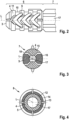
- the expansible fixing plug 1 extends from a rear end 2 along a longitudinal axis L, which runs longitudinally in the center of the expansible fixing plug 1, to a front end 3, which, when the expansible fixing plug 1 is installed as planned, first introduces a borehole (not shown) into the borehole becomes.
- the expansion anchor is intended for use in a drill hole with a nominal diameter of 8 millimeters, i.e. an 8 expansion anchor that has a length of approximately 50 millimeters.
- the expansion anchor 1 consists of a first anchor body 4 and a second anchor body 5, which is injected around the first anchor body 4.
- the expansion anchor 1 is produced in a two-component injection molding process, with the first anchor body 4 being injected from a first plastic component, a gray polyamide, and then the second anchor body 5 from a second plastic component, a harder, carbon-fibre-reinforced polyamide that is colored black the first anchor body 4 is injected.
- the carbon fiber reinforced polyamide has a greater Shore D hardness than the unreinforced polyamide of the first anchor body 4.
- the expansion dowel 1 has a front sleeve-like section 6 , behind which an expansion region 7 is arranged, which in turn is followed by a rear sleeve-like section 8 with the rear end 2 .
- the two anchor bodies 4, 5 are rotationally and axially connected to one another. Together they each form a sleeve for receiving a screw as an expanding element.
- the first anchor body 4 has in the front section 6 V-shaped connectors 9, circumferential grooves 10 and circumferential ribs 11 and in the rear section 8 also a circumferential groove 12 and anti-rotation ribs 13 on, which are encapsulated with the second plastic component of the second anchor body 5, whereby in the sections 6, 8 a positive connection between the two anchor bodies 4, 5 is formed.
- the rear section 8 also has a collar 14 which forms the rear end 2 of the expansible fixing plug 1 .
- the two anchor bodies 4, 5 together form the expansion area 7.
- the expansible fixing plug 1 has an oversize in the expansion area 7, so that the diameter of the expansible fixing plug 1 in the expansion area 7 is 8.4 millimeters.
- the dowel bodies 4 and 5 are each in one piece, such that the expansion legs 15, 16 are firmly connected to the front and rear sections 6, 8.
- the expansion legs 15, 16 are arranged alternately in the circumferential direction around an expansion channel 17 extending in the longitudinal direction from the rear end 2 to the front end 3, into which a screw as an expansion element can be inserted from behind through the rear sleeve-like section 8 to expand the expansion area 7.
- the expansion legs 15, 16 are thus made in pairs and over their entire length from the first or the second plastic component, but not from both plastic components.
- Arranged between the expansion legs 15, 16 are longitudinal slots 18 which are straight, run parallel to the longitudinal axis L and have a width of approximately 0.8 millimeters. Due to the longitudinal slots 18, the expansion legs 15, 16 do not touch in the circumferential direction. When inserting the expansible plug 1 into a borehole, the expansible area 7 is somewhat compressed due to the oversize, as a result of which the longitudinal slots 18 are at least partially closed.
- the expansion legs 15, 16 that are adjacent in the circumferential direction consist of the two different plastic components and the expansion legs 15, 16, which are made of the same plastic component, each lie in an axial plane, with the two axial planes being perpendicular to one another, so that the cross section is mirror-symmetrical to the Longitudinal axis L is.
- the expansion legs 15, 16 have different cross sections.
- the cross section of the second expansion legs 16, which are made from the harder plastic component, is smaller than that of the first expansion legs 15, which consist of the softer plastic component.
- the smaller one Cross-section of the second expansion legs 16 also leads to a lower resistance or to a smaller moment of resistance against a radial buckling of the expansion legs 15, 16 away from the longitudinal axis L.
- the connection of the harder plastic with the lower resistance or the larger cross section with the softer plastic results in a uniform spreading of the expansion area 7 of the expansion anchor 1 according to the invention.
- the use of the softer plastic component for the first expansion legs 15 with a larger cross section ensures slight buckling and/or knotting and, due to the relatively large cross section, the formation of a sufficiently large knot behind a panel-shaped building material, for example plasterboard, or a web of a perforated brick.
- the harder second expansion legs 16 also contribute to the formation of the knot, but due to their hardness in a solid building material, they can apply large expansion forces to the wall of the borehole in which the expansion anchor 1 is anchored.
- the hard second expansion legs 16 are used to guide a screw in the expansion channel 17 in the expansion area 7, since due to the hardness of the second expansion legs 16 it does not cut into them as well as into the first expansion legs 15 made from the first component.
- the harder ones second expansion leg 15 is hollow-round on its side facing the expansion channel 17, so that the second expansion leg 15 encloses the expansion channel 17 in the expansion area 7 over a larger circumference than the first expansion leg 15, which improves the guidance of the screw in the expansion channel 17.
- first expansion legs 15 also find a good hold in a borehole, they have longitudinal ribs 19 on an outside, which are interrupted by first predetermined buckling points 20 in the form of V-shaped depressions.
- the expansion anchor 1 according to the invention can be used universally in a wide variety of building materials due to its design. Nevertheless, it can be produced easily and inexpensively using the injection molding process.
Landscapes
- Engineering & Computer Science (AREA)
- General Engineering & Computer Science (AREA)
- Mechanical Engineering (AREA)
- Dowels (AREA)
- Joining Of Building Structures In Genera (AREA)
Claims (10)
- Cheville à expansion (1), laquelle présente un premier corps de cheville (4) en un premier composant en matière plastique et un second corps de cheville (5) en un second composant en matière plastique, les corps de cheville (4, 5) formant ensemble une zone d'expansion (7) dans laquelle des branches expansibles (15, 16) des corps de cheville (4, 5) sont disposées, dans la direction circonférentielle, autour d'un canal d'expansion (17) s'étendant dans la direction longitudinale de la cheville à expansion (1) et, dans la direction circonférentielle, sont espacées l'une de l'autre, caractérisée en ce
que les branches expansibles (15, 16) sont constituées de respectivement seulement l'un des composants en matière plastique. - Cheville à expansion selon la revendication 1, caractérisée en ce que des branches expansibles (15, 16) adjacentes dans la direction circonférentielle sont constituées de différents composants en matière plastique.
- Cheville à expansion selon la revendication 1 ou 2,
caractérisée en ce que des branches expansibles (15, 16) fabriquées à partir du même composant en matière plastique sont situées dans un plan axial. - Cheville à expansion selon l'une des revendications précédentes,
caractérisée en ce que des branches expansibles (15, 16) adjacentes dans la direction circonférentielle présentent des sections transversales différentes. - Cheville à expansion selon l'une des revendications précédentes,
caractérisée en ce que l'un des composants en matière plastique est plus dur que l'autre composant en matière plastique. - Cheville à expansion selon la revendication 5, caractérisée en ce qu'une branche expansible (16) fabriquée à partir du composant en matière plastique plus dur présente une section transversale plus petite qu'une branche expansible (15) fabriquée à partir du composant en matière plastique plus mou.
- Cheville à expansion selon la revendication 5 ou 6,
caractérisée en ce que des branches expansibles (16) fabriquées à partir du composant en matière plastique plus dur entourent le canal d'expansion (17) dans la zone d'expansion (7) sur une plus grande circonférence que celle des branches expansibles (15) fabriquées à partir du composant en matière plastique plus mou. - Cheville à expansion selon l'une des revendications précédentes,
caractérisée en ce qu'une branche expansible (15, 16) présente au moins un point de flexion théorique (20, 21). - Cheville à expansion selon l'une des revendications précédentes,
caractérisée en ce que les deux corps de cheville (4, 5) sont reliés entre eux de manière solidaire en rotation et de manière axialement fixe entre une extrémité avant (3) lors de l'introduction dans un trou percé au foret et la zone d'expansion (7). - Cheville à expansion selon l'une des revendications précédentes,
caractérisée en ce que les deux corps de cheville (4, 5) sont reliés entre eux de manière solidaire en rotation et de manière axialement fixe entre une extrémité arrière (2) lors de l'introduction dans un trou percé au foret et la zone d'expansion (7).
Applications Claiming Priority (1)
| Application Number | Priority Date | Filing Date | Title |
|---|---|---|---|
| DE102020129376.3A DE102020129376A1 (de) | 2020-11-07 | 2020-11-07 | Spreizdübel |
Publications (3)
| Publication Number | Publication Date |
|---|---|
| EP3995706A1 EP3995706A1 (fr) | 2022-05-11 |
| EP3995706C0 EP3995706C0 (fr) | 2023-08-30 |
| EP3995706B1 true EP3995706B1 (fr) | 2023-08-30 |
Family
ID=78500426
Family Applications (1)
| Application Number | Title | Priority Date | Filing Date |
|---|---|---|---|
| EP21205845.7A Active EP3995706B1 (fr) | 2020-11-07 | 2021-11-02 | Cheville à expansion |
Country Status (2)
| Country | Link |
|---|---|
| EP (1) | EP3995706B1 (fr) |
| DE (1) | DE102020129376A1 (fr) |
Cited By (1)
| Publication number | Priority date | Publication date | Assignee | Title |
|---|---|---|---|---|
| IT202300025176A1 (it) | 2023-11-27 | 2025-05-27 | Nobex S R L | Tassello ad espansione bi-materiale |
Families Citing this family (1)
| Publication number | Priority date | Publication date | Assignee | Title |
|---|---|---|---|---|
| DE102020130796A1 (de) | 2020-11-20 | 2022-05-25 | Fischerwerke Gmbh & Co. Kg | Spreizdübel |
Family Cites Families (7)
| Publication number | Priority date | Publication date | Assignee | Title |
|---|---|---|---|---|
| SE462602B (sv) * | 1989-01-11 | 1990-07-23 | Thorsman & Co Ab | Plugg |
| ITTO20080359A1 (it) | 2008-05-14 | 2009-11-15 | Itw Construction Products Ital | Tassello ad espansione |
| DE102013112233A1 (de) * | 2012-11-14 | 2014-05-15 | Fischerwerke Gmbh & Co. Kg | Spreizdübel |
| DE102013107075A1 (de) * | 2013-07-05 | 2015-01-08 | Fischerwerke Gmbh & Co. Kg | Spreizdübel |
| DE102014110737A1 (de) * | 2014-07-29 | 2016-02-04 | Fischerwerke Gmbh & Co. Kg | Spreizdübel |
| FR3027639B1 (fr) * | 2014-10-24 | 2017-05-19 | Ram Chevilles Et Fixations | Cheville a expansion universelle |
| DE202019100436U1 (de) * | 2018-06-29 | 2019-10-07 | Adolf Würth GmbH & Co. KG | Dübel mit flexibel gelagerter Mitdrehsicherung |
-
2020
- 2020-11-07 DE DE102020129376.3A patent/DE102020129376A1/de active Pending
-
2021
- 2021-11-02 EP EP21205845.7A patent/EP3995706B1/fr active Active
Cited By (2)
| Publication number | Priority date | Publication date | Assignee | Title |
|---|---|---|---|---|
| IT202300025176A1 (it) | 2023-11-27 | 2025-05-27 | Nobex S R L | Tassello ad espansione bi-materiale |
| EP4560153A1 (fr) | 2023-11-27 | 2025-05-28 | Nobex S.r.l. | Bouchon d'expansion bi-matériau |
Also Published As
| Publication number | Publication date |
|---|---|
| EP3995706A1 (fr) | 2022-05-11 |
| DE102020129376A1 (de) | 2022-05-12 |
| EP3995706C0 (fr) | 2023-08-30 |
Similar Documents
| Publication | Publication Date | Title |
|---|---|---|
| EP1135618B1 (fr) | Cheville a expansion | |
| EP1984632B1 (fr) | Cheville expansible | |
| EP3175128B1 (fr) | Cheville à expansion | |
| EP3175131B1 (fr) | Cheville à expansion | |
| DE102011000537A1 (de) | Spreizdübel | |
| EP3995706B1 (fr) | Cheville à expansion | |
| EP3175130B1 (fr) | Cheville à expansion | |
| EP3587838A1 (fr) | Goujon pourvu de brides expansibles destinées au nouage et de brides expansibles destinées au pliage | |
| DE3907034A1 (de) | Spreizduebel | |
| DE3831683A1 (de) | Spreizanker | |
| DE19700280C2 (de) | Schalungshilfsteil für eine Gewindehülse | |
| WO1997032142A1 (fr) | Cheville a percussion | |
| WO2008058621A1 (fr) | Cheville à expansion avec manchon flexible en direction axiale | |
| DE59703501C5 (de) | Spreizdübel | |
| EP3175129B1 (fr) | Cheville à expansion | |
| DE102023129496A1 (de) | Spreizdübel aus Kunststoff | |
| EP0964169B1 (fr) | Cheville pour cadres | |
| EP1298330B1 (fr) | Elément de fixation de panneaux isolants | |
| EP1205674B1 (fr) | Cheville à expansion | |
| EP4008917B1 (fr) | Cheville à expansion | |
| DE202020106135U1 (de) | Dübel und Befestigungssystem | |
| EP4246004B1 (fr) | Cheville à expansion et système de fixation | |
| EP4421332B1 (fr) | Cheville à expansion en matière plastique | |
| EP0913592B1 (fr) | Cheville à percussion | |
| DE1750243A1 (de) | Aus spritzfaehigem Werkstoff hergestellter Spreizduebel |
Legal Events
| Date | Code | Title | Description |
|---|---|---|---|
| PUAI | Public reference made under article 153(3) epc to a published international application that has entered the european phase |
Free format text: ORIGINAL CODE: 0009012 |
|
| STAA | Information on the status of an ep patent application or granted ep patent |
Free format text: STATUS: THE APPLICATION HAS BEEN PUBLISHED |
|
| AK | Designated contracting states |
Kind code of ref document: A1 Designated state(s): AL AT BE BG CH CY CZ DE DK EE ES FI FR GB GR HR HU IE IS IT LI LT LU LV MC MK MT NL NO PL PT RO RS SE SI SK SM TR |
|
| STAA | Information on the status of an ep patent application or granted ep patent |
Free format text: STATUS: REQUEST FOR EXAMINATION WAS MADE |
|
| 17P | Request for examination filed |
Effective date: 20221017 |
|
| RBV | Designated contracting states (corrected) |
Designated state(s): AL AT BE BG CH CY CZ DE DK EE ES FI FR GB GR HR HU IE IS IT LI LT LU LV MC MK MT NL NO PL PT RO RS SE SI SK SM TR |
|
| GRAP | Despatch of communication of intention to grant a patent |
Free format text: ORIGINAL CODE: EPIDOSNIGR1 |
|
| STAA | Information on the status of an ep patent application or granted ep patent |
Free format text: STATUS: GRANT OF PATENT IS INTENDED |
|
| INTG | Intention to grant announced |
Effective date: 20230331 |
|
| GRAS | Grant fee paid |
Free format text: ORIGINAL CODE: EPIDOSNIGR3 |
|
| GRAA | (expected) grant |
Free format text: ORIGINAL CODE: 0009210 |
|
| STAA | Information on the status of an ep patent application or granted ep patent |
Free format text: STATUS: THE PATENT HAS BEEN GRANTED |
|
| AK | Designated contracting states |
Kind code of ref document: B1 Designated state(s): AL AT BE BG CH CY CZ DE DK EE ES FI FR GB GR HR HU IE IS IT LI LT LU LV MC MK MT NL NO PL PT RO RS SE SI SK SM TR |
|
| REG | Reference to a national code |
Ref country code: GB Ref legal event code: FG4D Free format text: NOT ENGLISH |
|
| REG | Reference to a national code |
Ref country code: CH Ref legal event code: EP |
|
| REG | Reference to a national code |
Ref country code: DE Ref legal event code: R096 Ref document number: 502021001379 Country of ref document: DE |
|
| REG | Reference to a national code |
Ref country code: IE Ref legal event code: FG4D Free format text: LANGUAGE OF EP DOCUMENT: GERMAN |
|
| U01 | Request for unitary effect filed |
Effective date: 20230830 |
|
| U07 | Unitary effect registered |
Designated state(s): AT BE BG DE DK EE FI FR IT LT LU LV MT NL PT SE SI Effective date: 20230907 |
|
| U20 | Renewal fee for the european patent with unitary effect paid |
Year of fee payment: 3 Effective date: 20231011 |
|
| PG25 | Lapsed in a contracting state [announced via postgrant information from national office to epo] |
Ref country code: GR Free format text: LAPSE BECAUSE OF FAILURE TO SUBMIT A TRANSLATION OF THE DESCRIPTION OR TO PAY THE FEE WITHIN THE PRESCRIBED TIME-LIMIT Effective date: 20231201 |
|
| PG25 | Lapsed in a contracting state [announced via postgrant information from national office to epo] |
Ref country code: IS Free format text: LAPSE BECAUSE OF FAILURE TO SUBMIT A TRANSLATION OF THE DESCRIPTION OR TO PAY THE FEE WITHIN THE PRESCRIBED TIME-LIMIT Effective date: 20231230 |
|
| PG25 | Lapsed in a contracting state [announced via postgrant information from national office to epo] |
Ref country code: RS Free format text: LAPSE BECAUSE OF FAILURE TO SUBMIT A TRANSLATION OF THE DESCRIPTION OR TO PAY THE FEE WITHIN THE PRESCRIBED TIME-LIMIT Effective date: 20230830 Ref country code: NO Free format text: LAPSE BECAUSE OF FAILURE TO SUBMIT A TRANSLATION OF THE DESCRIPTION OR TO PAY THE FEE WITHIN THE PRESCRIBED TIME-LIMIT Effective date: 20231130 Ref country code: IS Free format text: LAPSE BECAUSE OF FAILURE TO SUBMIT A TRANSLATION OF THE DESCRIPTION OR TO PAY THE FEE WITHIN THE PRESCRIBED TIME-LIMIT Effective date: 20231230 Ref country code: HR Free format text: LAPSE BECAUSE OF FAILURE TO SUBMIT A TRANSLATION OF THE DESCRIPTION OR TO PAY THE FEE WITHIN THE PRESCRIBED TIME-LIMIT Effective date: 20230830 Ref country code: GR Free format text: LAPSE BECAUSE OF FAILURE TO SUBMIT A TRANSLATION OF THE DESCRIPTION OR TO PAY THE FEE WITHIN THE PRESCRIBED TIME-LIMIT Effective date: 20231201 |
|
| PG25 | Lapsed in a contracting state [announced via postgrant information from national office to epo] |
Ref country code: PL Free format text: LAPSE BECAUSE OF FAILURE TO SUBMIT A TRANSLATION OF THE DESCRIPTION OR TO PAY THE FEE WITHIN THE PRESCRIBED TIME-LIMIT Effective date: 20230830 |
|
| PG25 | Lapsed in a contracting state [announced via postgrant information from national office to epo] |
Ref country code: ES Free format text: LAPSE BECAUSE OF FAILURE TO SUBMIT A TRANSLATION OF THE DESCRIPTION OR TO PAY THE FEE WITHIN THE PRESCRIBED TIME-LIMIT Effective date: 20230830 |
|
| PG25 | Lapsed in a contracting state [announced via postgrant information from national office to epo] |
Ref country code: SM Free format text: LAPSE BECAUSE OF FAILURE TO SUBMIT A TRANSLATION OF THE DESCRIPTION OR TO PAY THE FEE WITHIN THE PRESCRIBED TIME-LIMIT Effective date: 20230830 Ref country code: RO Free format text: LAPSE BECAUSE OF FAILURE TO SUBMIT A TRANSLATION OF THE DESCRIPTION OR TO PAY THE FEE WITHIN THE PRESCRIBED TIME-LIMIT Effective date: 20230830 Ref country code: ES Free format text: LAPSE BECAUSE OF FAILURE TO SUBMIT A TRANSLATION OF THE DESCRIPTION OR TO PAY THE FEE WITHIN THE PRESCRIBED TIME-LIMIT Effective date: 20230830 Ref country code: CZ Free format text: LAPSE BECAUSE OF FAILURE TO SUBMIT A TRANSLATION OF THE DESCRIPTION OR TO PAY THE FEE WITHIN THE PRESCRIBED TIME-LIMIT Effective date: 20230830 Ref country code: SK Free format text: LAPSE BECAUSE OF FAILURE TO SUBMIT A TRANSLATION OF THE DESCRIPTION OR TO PAY THE FEE WITHIN THE PRESCRIBED TIME-LIMIT Effective date: 20230830 |
|
| REG | Reference to a national code |
Ref country code: DE Ref legal event code: R097 Ref document number: 502021001379 Country of ref document: DE |
|
| PG25 | Lapsed in a contracting state [announced via postgrant information from national office to epo] |
Ref country code: MC Free format text: LAPSE BECAUSE OF FAILURE TO SUBMIT A TRANSLATION OF THE DESCRIPTION OR TO PAY THE FEE WITHIN THE PRESCRIBED TIME-LIMIT Effective date: 20230830 |
|
| PLBE | No opposition filed within time limit |
Free format text: ORIGINAL CODE: 0009261 |
|
| STAA | Information on the status of an ep patent application or granted ep patent |
Free format text: STATUS: NO OPPOSITION FILED WITHIN TIME LIMIT |
|
| PG25 | Lapsed in a contracting state [announced via postgrant information from national office to epo] |
Ref country code: MC Free format text: LAPSE BECAUSE OF FAILURE TO SUBMIT A TRANSLATION OF THE DESCRIPTION OR TO PAY THE FEE WITHIN THE PRESCRIBED TIME-LIMIT Effective date: 20230830 |
|
| 26N | No opposition filed |
Effective date: 20240603 |
|
| REG | Reference to a national code |
Ref country code: IE Ref legal event code: MM4A |
|
| PG25 | Lapsed in a contracting state [announced via postgrant information from national office to epo] |
Ref country code: IE Free format text: LAPSE BECAUSE OF NON-PAYMENT OF DUE FEES Effective date: 20231102 |
|
| PG25 | Lapsed in a contracting state [announced via postgrant information from national office to epo] |
Ref country code: IE Free format text: LAPSE BECAUSE OF NON-PAYMENT OF DUE FEES Effective date: 20231102 |
|
| U20 | Renewal fee for the european patent with unitary effect paid |
Year of fee payment: 4 Effective date: 20241021 |
|
| REG | Reference to a national code |
Ref country code: CH Ref legal event code: PL |
|
| REG | Reference to a national code |
Ref country code: CH Ref legal event code: PL |
|
| PG25 | Lapsed in a contracting state [announced via postgrant information from national office to epo] |
Ref country code: CH Free format text: LAPSE BECAUSE OF NON-PAYMENT OF DUE FEES Effective date: 20241130 |
|
| PG25 | Lapsed in a contracting state [announced via postgrant information from national office to epo] |
Ref country code: CY Free format text: LAPSE BECAUSE OF FAILURE TO SUBMIT A TRANSLATION OF THE DESCRIPTION OR TO PAY THE FEE WITHIN THE PRESCRIBED TIME-LIMIT; INVALID AB INITIO Effective date: 20211102 |
|
| U20 | Renewal fee for the european patent with unitary effect paid |
Year of fee payment: 5 Effective date: 20250923 |
|
| PG25 | Lapsed in a contracting state [announced via postgrant information from national office to epo] |
Ref country code: TR Free format text: LAPSE BECAUSE OF FAILURE TO SUBMIT A TRANSLATION OF THE DESCRIPTION OR TO PAY THE FEE WITHIN THE PRESCRIBED TIME-LIMIT Effective date: 20230830 |
|
| PG25 | Lapsed in a contracting state [announced via postgrant information from national office to epo] |
Ref country code: HU Free format text: LAPSE BECAUSE OF FAILURE TO SUBMIT A TRANSLATION OF THE DESCRIPTION OR TO PAY THE FEE WITHIN THE PRESCRIBED TIME-LIMIT; INVALID AB INITIO Effective date: 20211102 |