EP4001045A1 - Dispositif de sécurité pour plateforme locomotive électrique pouvant maintenir un intervalle entre des câbles - Google Patents
Dispositif de sécurité pour plateforme locomotive électrique pouvant maintenir un intervalle entre des câbles Download PDFInfo
- Publication number
- EP4001045A1 EP4001045A1 EP20209147.6A EP20209147A EP4001045A1 EP 4001045 A1 EP4001045 A1 EP 4001045A1 EP 20209147 A EP20209147 A EP 20209147A EP 4001045 A1 EP4001045 A1 EP 4001045A1
- Authority
- EP
- European Patent Office
- Prior art keywords
- ropes
- safety device
- buffer
- interval
- electric locomotive
- Prior art date
- Legal status (The legal status is an assumption and is not a legal conclusion. Google has not performed a legal analysis and makes no representation as to the accuracy of the status listed.)
- Withdrawn
Links
- 230000003137 locomotive effect Effects 0.000 title claims abstract description 22
- 238000012423 maintenance Methods 0.000 claims abstract description 10
- 239000000463 material Substances 0.000 claims description 5
- 239000007779 soft material Substances 0.000 claims description 3
- 230000006378 damage Effects 0.000 description 10
- 208000027418 Wounds and injury Diseases 0.000 description 6
- 208000014674 injury Diseases 0.000 description 6
- 229920003002 synthetic resin Polymers 0.000 description 2
- 239000000057 synthetic resin Substances 0.000 description 2
- 230000000903 blocking effect Effects 0.000 description 1
- 238000004519 manufacturing process Methods 0.000 description 1
Images



Classifications
-
- B—PERFORMING OPERATIONS; TRANSPORTING
- B61—RAILWAYS
- B61B—RAILWAY SYSTEMS; EQUIPMENT THEREFOR NOT OTHERWISE PROVIDED FOR
- B61B1/00—General arrangement of stations, platforms, or sidings; Railway networks; Rail vehicle marshalling systems
- B61B1/02—General arrangement of stations and platforms including protection devices for the passengers
Definitions
- the present disclosure relates to a safety device for an electric locomotive platform capable of maintaining an interval between ropes and, more particularly, to a safety device for an electric locomotive platform capable of minimizing an occurrence of a safety accident by maintaining a vertical interval of ropes.
- a safety device for an electric locomotive platform includes: at least one pair or more of lift driving units 10 installed at a selected position between an entrance of a platform to which an electric locomotive enters and an exit of the platform; movement bodies 20 on opposite sides of the ropes and each provided on an inner side of each of a pair of lift driving units 10 and each moved in an up-and-down (i.e., vertical) direction by each of the lift driving units 10; and a plurality of ropes 30 connecting the movement bodies 20 on the opposite sides of the ropes 30 to each other in a horizontal direction.
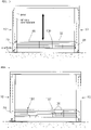
- This device is capable of blocking passage by lowering the ropes 30 when passengers are waiting on a platform (see FIG. 1 ), and allowing the passage by raising the ropes 30 when the passengers are on board an electric locomotive (see FIG. 2 ).
- An exemplary embodiment of the present disclosure is described to provide a safety device for an electric locomotive platform, wherein ropes are connected and fixed to each other in a vertical direction to prevent a passenger from easily widening or deforming the ropes.
- the exemplary embodiment of the present disclosure is described to provide a safety device for an electric locomotive platform capable of preventing injury or damage by performing a buffer function when ropes moving up and down collide with a passenger or an obstacle.
- the exemplary embodiment of the present disclosure is described to provide a safety device for an electric locomotive platform capable of maintaining tension by fixing the remaining ropes even when any one of the ropes is cut.
- a safety device for an electric locomotive platform including: at least one pair or more of lift driving units 10 provided at a selected position between an entrance of the platform to which an electric locomotive enters and an exit of the platform; movement bodies 20 provided on opposite sides of ropes and each moved in an up-and-down direction by each of the pair of the lift driving units 10; a plurality of ropes 30 disposed at an interval therebetween so as to be spaced apart from each other in the up-and-down direction between the pair of the lift driving units 10, and connecting the movement bodies 20 on the opposite sides of the ropes to each other in a horizontal direction; and a rope interval maintenance unit 100 securing each interval of the plurality of ropes 30 by connecting the plurality of ropes 30 to each other in a vertical direction so as to suppress the plurality of ropes 30 from being deformed by an external force and suppress each interval of the plurality of ropes 30 from being changed.
- Each of the movement bodies 20 on opposite sides of the ropes may be provided on an inner side of each of a pair of lift driving units 10.
- the rope interval maintenance unit 100 may include: a fixing part 110 provided to fix the plurality of ropes 30 to each other in the vertical direction; a first buffer part 120 fixing a rope provided at a lowest position of the ropes 30 to a lower part of the fixing part 110 to be able to perform a buffer function in an event of colliding with a passenger or an obstacle; and a second buffer part 130 fixing a rope provided at a highest position of the ropes 30 to an upper part of the fixing part 110 to be able to perform a buffer function in an event of colliding with a passenger or an obstacle.
- the first buffer part 120 and the second buffer part 130 may respectively have buffer spaces 121 and 131 therein through which, among the plurality of ropes 30, the lowermost and uppermost ropes may pass in the horizontal direction, the buffer spaces being formed to cushion a collision in the vertical direction in the event of colliding with a passenger or an obstacle.
- the fixing part 110 may be formed of a hard material, and the first buffer part 120 and the second buffer part 130 may be formed of a soft material.
- ropes are connected and fixed to each other in a vertical direction so that a passenger may not easily widen or deform the ropes, thereby preventing a safety accident from occurring.
- a buffer function is performed, thereby preventing injury or damage from occurring.
- tension of the ropes may be maintained by fixing the remaining ropes to each other, an action to block or allow passage for the passenger may be performed continually.
- a structure of the safety device is simple and maintenance is easy, thereby improving durability and service life.
- a safety device for an electric locomotive platform may minimize an occurrence of a safety accident by maintaining a vertical interval of a rope as an interval that is set during manufacturing of the rope.
- Such a configuration of the safety device for the electric locomotive platform according to the exemplary embodiment of the present disclosure are shown in FIGS. 3 to 10 .
- the safety device for the electric locomotive platform includes: at least one pair or more of lift driving units 10 installed at a selected position between an entrance of a platform to which an electric locomotive enters and an exit of the platform; movement bodies 20 on opposite sides of the ropes and each moved in an up-and-down (i.e., vertical) direction by each of a pair of the lift driving units 10; a plurality of ropes 30 disposed at an interval so as to be spaced apart from each other in the up-and-down (i.e., vertical) direction between the lift driving units 10 that form a pair, and connecting the movement body 20 on the opposite sides to each other in a horizontal direction; and at least one or more of rope interval maintenance units 100 securing each interval of the plurality of ropes 30 by connecting the plurality of ropes 30 to each other in a vertical direction so as to suppress the plurality of ropes 30 from being deformed by an external force and suppress each interval of the plurality of ropes
- the lift driving units 10 that form a pair may be disposed at a regular distance so as to be spaced apart from each other along a longitudinal direction of the platform and may face each other.
- Each of the lift driving units 10 that form a pair may include a post constituting a main body.
- Each of the posts may be erected on the platform in the vertical direction and be formed to have a predetermined height.
- a driving mechanism for moving each of the movement bodies 20 of the opposite sides thereof in the vertical direction may be provided inside of each post.
- the driving mechanism may be applied in various configurations such as a combination of a chain and sprocket with a motor, and a combination of a cylinder or screw jack with a motor.
- the ropes 30 are coated with a rubber or synthetic resin material on an outer side thereof to prevent decay, as well as to minimize injury when colliding with a passenger.
- the rope interval maintenance unit 100 connects the ropes 30 to each other in the vertical direction to secure the vertical interval of the ropes 30, thereby serving to prevent the ropes 30 from being deformed by a passenger who holds the rope 30 to twist the rope 30 or widen the interval between the ropes 30.
- such a rope interval maintenance unit 100 includes: a fixing part 110 provided to fix the ropes 30 to each other in the vertical direction; a first buffer part 120 fixing a rope at the lowest position of the ropes 30 to a lower part of the fixing part 110 to be able to perform a buffer function in an event of colliding with a passenger or an obstacle; and a second buffer part 130 fixing a rope at the highest position of the ropes 30 to an upper part of the fixing part 110 to be able to perform the buffer function in the event of colliding with a passenger or an obstacle.
- the fixing part 110 is provided with a pair thereof positioned in the front and rear of the ropes 30 and the pair is firmly fastened to each other by fasteners 112 such as bolts and nuts, so that, excluding the uppermost and lowermost ropes among the ropes 30, the remaining ropes positioned therebetween are pressed, thereby preventing deformation in which the ropes 30 are twisted by an external force or the interval between the ropes 30 is widened, thereby being able to maintain the vertical interval constant.
- the pair of fixing parts 110 may be provided with a pressure groove 111 into which the ropes 30 are inserted.
- Such a pair of fixing parts 110 may be provided in a bar shape by using a hard material such as a synthetic resin material.
- the first buffer part 120 and the second buffer part 130 perform the buffer function in the event when the ropes 30 moving in the vertical direction collide with a passenger or an obstacle, thereby preventing the injury or damage from occurring.
- the first buffer part 120 and the second buffer part 130 may include buffer spaces 121 and 131 each inside of the first buffer part 120 and the second buffer part 130 each provided with the lowermost and uppermost ropes among the ropes 30 passing in the horizontal direction and formed to cushion a collision in the vertical direction in the event of colliding with a passenger or an obstacle.
- the buffer spaces 121 and 131 are each provided with a certain space so that the lowermost and uppermost ropes 30 may be shaken in the vertical direction without fixing the lowermost and uppermost ropes 30, thereby performing the buffer function in the event of colliding with a passenger or an obstacle while the ropes are moving.
- the first buffer part 120 and the second buffer part 130 are configured to entirely surround the outer diameters of the lowermost and uppermost ropes 30 respectively, and are made of a soft material, thereby minimizing injury caused by an event of colliding with a passenger.
Landscapes
- Engineering & Computer Science (AREA)
- Transportation (AREA)
- Mechanical Engineering (AREA)
- Platform Screen Doors And Railroad Systems (AREA)
Priority Applications (1)
| Application Number | Priority Date | Filing Date | Title |
|---|---|---|---|
| EP20209147.6A EP4001045A1 (fr) | 2020-11-23 | 2020-11-23 | Dispositif de sécurité pour plateforme locomotive électrique pouvant maintenir un intervalle entre des câbles |
Applications Claiming Priority (1)
| Application Number | Priority Date | Filing Date | Title |
|---|---|---|---|
| EP20209147.6A EP4001045A1 (fr) | 2020-11-23 | 2020-11-23 | Dispositif de sécurité pour plateforme locomotive électrique pouvant maintenir un intervalle entre des câbles |
Publications (1)
| Publication Number | Publication Date |
|---|---|
| EP4001045A1 true EP4001045A1 (fr) | 2022-05-25 |
Family
ID=73544011
Family Applications (1)
| Application Number | Title | Priority Date | Filing Date |
|---|---|---|---|
| EP20209147.6A Withdrawn EP4001045A1 (fr) | 2020-11-23 | 2020-11-23 | Dispositif de sécurité pour plateforme locomotive électrique pouvant maintenir un intervalle entre des câbles |
Country Status (1)
| Country | Link |
|---|---|
| EP (1) | EP4001045A1 (fr) |
Citations (11)
| Publication number | Priority date | Publication date | Assignee | Title |
|---|---|---|---|---|
| KR100601112B1 (ko) | 2005-02-14 | 2006-07-19 | 주식회사 에스케이디 하이테크 | 전동차 플랫폼의 안전장치 |
| JP2008534827A (ja) | 2005-04-04 | 2008-08-28 | ドナルド スチュワート ネイピア | 柵システム |
| KR101143843B1 (ko) | 2011-11-30 | 2012-05-04 | (주) 금동강건 | 도로용 가드케이블 |
| WO2013133631A1 (fr) * | 2012-03-06 | 2013-09-12 | 한국교통연구원 | Appareil de sécurité pour plateforme de train |
| KR20140007980A (ko) | 2014-01-02 | 2014-01-20 | 한국교통연구원 | 장애물 감지장치를 구비하는 승하강 방식의 전동차 플랫폼 안전장치 |
| KR20140009813A (ko) | 2012-07-13 | 2014-01-23 | 한국교통연구원 | 전동차 플랫폼 안전장치 |
| KR101471543B1 (ko) | 2012-06-07 | 2014-12-11 | 한국교통연구원 | 장애물 감지장치를 구비하는 승하강 방식의 전동차 플랫폼 안전장치 |
| KR20150013410A (ko) | 2014-12-23 | 2015-02-05 | 한국교통연구원 | 수직개폐형 스크린도어의 승하강장치 |
| KR20150013411A (ko) | 2014-12-23 | 2015-02-05 | 한국교통연구원 | 수직개폐형 스크린도어의 승하강장치 |
| TWI643774B (zh) * | 2017-12-07 | 2018-12-11 | 韓商Skd高科技股份有限公司 | 包括繩索安全部件的電車平臺安全裝置 |
| KR20190120482A (ko) | 2018-04-16 | 2019-10-24 | 주식회사 에스케이디 하이테크 | 전동차 플랫폼 안전장치 |
-
2020
- 2020-11-23 EP EP20209147.6A patent/EP4001045A1/fr not_active Withdrawn
Patent Citations (11)
| Publication number | Priority date | Publication date | Assignee | Title |
|---|---|---|---|---|
| KR100601112B1 (ko) | 2005-02-14 | 2006-07-19 | 주식회사 에스케이디 하이테크 | 전동차 플랫폼의 안전장치 |
| JP2008534827A (ja) | 2005-04-04 | 2008-08-28 | ドナルド スチュワート ネイピア | 柵システム |
| KR101143843B1 (ko) | 2011-11-30 | 2012-05-04 | (주) 금동강건 | 도로용 가드케이블 |
| WO2013133631A1 (fr) * | 2012-03-06 | 2013-09-12 | 한국교통연구원 | Appareil de sécurité pour plateforme de train |
| KR101471543B1 (ko) | 2012-06-07 | 2014-12-11 | 한국교통연구원 | 장애물 감지장치를 구비하는 승하강 방식의 전동차 플랫폼 안전장치 |
| KR20140009813A (ko) | 2012-07-13 | 2014-01-23 | 한국교통연구원 | 전동차 플랫폼 안전장치 |
| KR20140007980A (ko) | 2014-01-02 | 2014-01-20 | 한국교통연구원 | 장애물 감지장치를 구비하는 승하강 방식의 전동차 플랫폼 안전장치 |
| KR20150013410A (ko) | 2014-12-23 | 2015-02-05 | 한국교통연구원 | 수직개폐형 스크린도어의 승하강장치 |
| KR20150013411A (ko) | 2014-12-23 | 2015-02-05 | 한국교통연구원 | 수직개폐형 스크린도어의 승하강장치 |
| TWI643774B (zh) * | 2017-12-07 | 2018-12-11 | 韓商Skd高科技股份有限公司 | 包括繩索安全部件的電車平臺安全裝置 |
| KR20190120482A (ko) | 2018-04-16 | 2019-10-24 | 주식회사 에스케이디 하이테크 | 전동차 플랫폼 안전장치 |
Similar Documents
| Publication | Publication Date | Title |
|---|---|---|
| KR101547650B1 (ko) | 전동차 플랫폼 안전장치 | |
| US20130056305A1 (en) | Elevator With Cogged Belt and Pulley and With Counterweight | |
| EP4001045A1 (fr) | Dispositif de sécurité pour plateforme locomotive électrique pouvant maintenir un intervalle entre des câbles | |
| CN110116954B (zh) | 双层电梯系统 | |
| EP2848572A1 (fr) | Marche d'escalier mécanique et escalier mécanique comportant celle-ci | |
| US8807289B2 (en) | Elevator pit barrier | |
| EP1638882B1 (fr) | Plaque de support compacte comprenant des elements d'arrimage d'extremite integres, accessibles | |
| KR20220054129A (ko) | 차량 방호 안전 펜스 | |
| CN113944127A (zh) | 一种公路交通安全设施工程用防撞护栏 | |
| US10513241B2 (en) | Compact force limiter for automotive safety restraints | |
| CN1615269A (zh) | 电梯装置 | |
| CN205527146U (zh) | 电梯的主绳索松弛检测装置及电梯 | |
| KR102687307B1 (ko) | 개방형 지주와 경사형 이음재를 적용한 차량 방호 울타리 | |
| CN211393455U (zh) | 高速梯的补偿绳端接装置 | |
| JPWO2006018868A1 (ja) | エレベータ装置 | |
| TW201924995A (zh) | 包括繩索安全部件的電車平臺安全裝置 | |
| JP7523655B1 (ja) | エレベータのロープ把持装置 | |
| EP1934126B1 (fr) | Contrepoids avec un tampon partiellement encastre | |
| KR102808188B1 (ko) | 전동차 플랫폼 안전장치 | |
| KR102325531B1 (ko) | 분리방지형 추락방지도어를 포함하는 주차구조물의 진출입 도어 어셈블리 | |
| KR102862496B1 (ko) | 차량 방호울타리 충격완화장치 | |
| CN221459555U (zh) | 一种用于乘用电梯轿厢架的高强度下梁 | |
| WO2006097139A1 (fr) | Ascenseur | |
| KR102807595B1 (ko) | 차량 충돌 시 순차적 충격흡수가 가능한 보행자 방호펜스 | |
| KR102885486B1 (ko) | 차량용 시트 슬라이딩 장치 |
Legal Events
| Date | Code | Title | Description |
|---|---|---|---|
| PUAI | Public reference made under article 153(3) epc to a published international application that has entered the european phase |
Free format text: ORIGINAL CODE: 0009012 |
|
| STAA | Information on the status of an ep patent application or granted ep patent |
Free format text: STATUS: REQUEST FOR EXAMINATION WAS MADE |
|
| 17P | Request for examination filed |
Effective date: 20201124 |
|
| AK | Designated contracting states |
Kind code of ref document: A1 Designated state(s): AL AT BE BG CH CY CZ DE DK EE ES FI FR GB GR HR HU IE IS IT LI LT LU LV MC MK MT NL NO PL PT RO RS SE SI SK SM TR |
|
| STAA | Information on the status of an ep patent application or granted ep patent |
Free format text: STATUS: THE APPLICATION IS DEEMED TO BE WITHDRAWN |
|
| 18D | Application deemed to be withdrawn |
Effective date: 20221126 |