EP4010234B1 - Procédé de détermination d'une vitesse locale d'une voiture - Google Patents
Procédé de détermination d'une vitesse locale d'une voiture Download PDFInfo
- Publication number
- EP4010234B1 EP4010234B1 EP20749841.1A EP20749841A EP4010234B1 EP 4010234 B1 EP4010234 B1 EP 4010234B1 EP 20749841 A EP20749841 A EP 20749841A EP 4010234 B1 EP4010234 B1 EP 4010234B1
- Authority
- EP
- European Patent Office
- Prior art keywords
- carriage
- speed
- wheel
- acceleration
- determined
- Prior art date
- Legal status (The legal status is an assumption and is not a legal conclusion. Google has not performed a legal analysis and makes no representation as to the accuracy of the status listed.)
- Active
Links
Images


Classifications
-
- B—PERFORMING OPERATIONS; TRANSPORTING
- B61—RAILWAYS
- B61L—GUIDING RAILWAY TRAFFIC; ENSURING THE SAFETY OF RAILWAY TRAFFIC
- B61L25/00—Recording or indicating positions or identities of vehicles or trains or setting of track apparatus
- B61L25/02—Indicating or recording positions or identities of vehicles or trains
- B61L25/021—Measuring and recording of train speed
-
- B—PERFORMING OPERATIONS; TRANSPORTING
- B60—VEHICLES IN GENERAL
- B60T—VEHICLE BRAKE CONTROL SYSTEMS OR PARTS THEREOF; BRAKE CONTROL SYSTEMS OR PARTS THEREOF, IN GENERAL; ARRANGEMENT OF BRAKING ELEMENTS ON VEHICLES IN GENERAL; PORTABLE DEVICES FOR PREVENTING UNWANTED MOVEMENT OF VEHICLES; VEHICLE MODIFICATIONS TO FACILITATE COOLING OF BRAKES
- B60T8/00—Arrangements for adjusting wheel-braking force to meet varying vehicular or ground-surface conditions, e.g. limiting or varying distribution of braking force
- B60T8/17—Using electrical or electronic regulation means to control braking
- B60T8/1701—Braking or traction control means specially adapted for particular types of vehicles
- B60T8/1705—Braking or traction control means specially adapted for particular types of vehicles for rail vehicles
-
- B—PERFORMING OPERATIONS; TRANSPORTING
- B60—VEHICLES IN GENERAL
- B60T—VEHICLE BRAKE CONTROL SYSTEMS OR PARTS THEREOF; BRAKE CONTROL SYSTEMS OR PARTS THEREOF, IN GENERAL; ARRANGEMENT OF BRAKING ELEMENTS ON VEHICLES IN GENERAL; PORTABLE DEVICES FOR PREVENTING UNWANTED MOVEMENT OF VEHICLES; VEHICLE MODIFICATIONS TO FACILITATE COOLING OF BRAKES
- B60T8/00—Arrangements for adjusting wheel-braking force to meet varying vehicular or ground-surface conditions, e.g. limiting or varying distribution of braking force
- B60T8/17—Using electrical or electronic regulation means to control braking
- B60T8/172—Determining control parameters used in the regulation, e.g. by calculations involving measured or detected parameters
-
- B—PERFORMING OPERATIONS; TRANSPORTING
- B60—VEHICLES IN GENERAL
- B60W—CONJOINT CONTROL OF VEHICLE SUB-UNITS OF DIFFERENT TYPE OR DIFFERENT FUNCTION; CONTROL SYSTEMS SPECIALLY ADAPTED FOR HYBRID VEHICLES; ROAD VEHICLE DRIVE CONTROL SYSTEMS FOR PURPOSES NOT RELATED TO THE CONTROL OF A PARTICULAR SUB-UNIT
- B60W40/00—Estimation or calculation of non-directly measurable driving parameters for road vehicle drive control systems not related to the control of a particular sub unit, e.g. by using mathematical models
- B60W40/10—Estimation or calculation of non-directly measurable driving parameters for road vehicle drive control systems not related to the control of a particular sub unit, e.g. by using mathematical models related to vehicle motion
- B60W40/105—Speed
-
- G—PHYSICS
- G01—MEASURING; TESTING
- G01P—MEASURING LINEAR OR ANGULAR SPEED, ACCELERATION, DECELERATION, OR SHOCK; INDICATING PRESENCE, ABSENCE, OR DIRECTION, OF MOVEMENT
- G01P3/00—Measuring linear or angular speed; Measuring differences of linear or angular speeds
- G01P3/42—Devices characterised by the use of electric or magnetic means
- G01P3/50—Devices characterised by the use of electric or magnetic means for measuring linear speed
-
- B—PERFORMING OPERATIONS; TRANSPORTING
- B60—VEHICLES IN GENERAL
- B60T—VEHICLE BRAKE CONTROL SYSTEMS OR PARTS THEREOF; BRAKE CONTROL SYSTEMS OR PARTS THEREOF, IN GENERAL; ARRANGEMENT OF BRAKING ELEMENTS ON VEHICLES IN GENERAL; PORTABLE DEVICES FOR PREVENTING UNWANTED MOVEMENT OF VEHICLES; VEHICLE MODIFICATIONS TO FACILITATE COOLING OF BRAKES
- B60T2250/00—Monitoring, detecting, estimating vehicle conditions
- B60T2250/04—Vehicle reference speed; Vehicle body speed
Definitions
- the invention relates to a method for determining a carriage speed of a carriage and of a train with at least one carriage, a device designed to carry out the method, a carriage with this device and a computer program product.
- GNSS global satellite navigation system
- GLONASS global satellite navigation system
- the true position is superimposed with a mean-free measurement noise, the standard deviation of which can be estimated from the number of satellites received.
- the reception is poor, the accuracy can be drastically reduced or reception can fail completely, for example in a tunnel.
- Position determination using train control systems is generally only possible at specific points or in sections and is therefore not suitable for continuous evaluation.
- a speed signal from the so-called wheel slide protection which is either provided by a reference wheel set or determined over several or all wheel sets, for example by averaging, has the problem that a systematic measurement inaccuracy can be caused due to an unknown wheel diameter, which changes slowly over time.
- a braking or acceleration force can be determined approximately from the state variables of a drive or a brake.
- inaccuracies in the determination of these forces arise, for example due to a lack of knowledge of the exact coefficient of friction between the brake disc and brake pad and an exact point of force application or the non-ideal force transmission.
- document US 9 517 780 B2 discloses a method for determining a car speed.
- sensor data available in the car are recorded as a respective input variable for an observer model, the input variables are entered into the observer model and a continuous determination of the car speed is carried out by the observer model.
- the invention is based on the object of providing a possibility to determine a speed of a carriage and of a rail vehicle consisting of at least one carriage as reliably as possible from the available information.
- Detecting here can be understood as both the measurement of corresponding quantities and their determination or calculation from other quantities.
- a wheel speed can be detected by measuring it.
- the application force of a friction brake can be detected by calculating it from a brake pressure.
- the observer model is preferably designed as a control engineering observer model, wherein in a preferred embodiment it is designed as a Luenberger observer or Kalman filter.
- the sensor data includes a longitudinal acceleration of the vehicle and/or a rotational speed of a vehicle element whose rotational speed is proportional to a wheel speed.
- the carriage element is preferably a wheel, an axle of the carriage or a shaft of a motor of the carriage, wherein the proportionality factor is preferably a wheel radius, a gear ratio and/or another factor which is designed to determine a peripheral speed of the wheel from the detected rotational speed, which is preferably used as the wheel speed.
- the speed is preferably measured using a speed sensor or pulse generator.
- the acceleration is preferably measured using acceleration sensors, which are preferably designed in the form of a MEMS (microelectromechanical system), and preferably used in an inertial measuring system.
- MEMS microelectromechanical system
- the acceleration can particularly preferably be detected from a high-precision aligned single-axis sensor, or the sensor system has additional sensors in orthogonal spatial directions and can be corrected using a calibration procedure.
- the input variables contain measurable forces or, preferably by means of an observer model, indirectly determined forces introduced by the braking or drive systems of the vehicle.
- These forces can be determined, for example, by determining the application forces of friction brakes or the drive torque of a motor. These are preferably forces that are supported on the rail via the corresponding wheel of the wagon whose wheel speed is used. This means that physical quantities are available that have an influence on the correlation of the wheel speed with the actual wagon speed.
- the observer model uses a speed and an acceleration of the car as state variables, wherein preferably the speed is the determined car speed and/or the acceleration is a longitudinal acceleration of the car.
- a method for determining a carriage speed of a carriage of a rail vehicle includes the steps of: detecting speed-relevant sensor data available locally in the carriage as a respective input variable for a control-engineering observer model, entering the input variables into the control-engineering observer model; carrying out continuous processing of the input variables and determining state variables by the control-engineering observer model, wherein one of the state variables is preferably the carriage speed.
- This method enables the vehicle speed to be determined precisely and continuously from the locally available sensor data. Due to the continuous determination of the local vehicle speed, this can be determined independently of a Driving condition, can be reliably used for example for anti-skid protection, adhesion detection or inclination detection.
- continuous determination means in particular that there is no need to switch between different calculation methods due to different driving conditions. For example, in switching methods, a mode is switched in which wheel speed or wheel speed is no longer used if the wheel is skidding or locking. Instead, in continuous determination, the same measured variables are always used to determine the vehicle speed.
- the method according to the invention is preferably designed to adapt the influence of the corresponding variables, such as acceleration or longitudinal acceleration or wheel speed, on the determined vehicle speed itself.
- State variables can be determined using the observer model, which preferably functions as a simulation model of a system and into which measurement results from sensors can be entered as input variables of the observer model as output variables of the system.
- the state variables can, for example, be more precise or corrected measurement results from the sensors.
- hidden state variables can also be determined that cannot be measured directly or can only be measured with great effort.
- the state variables are determined using equations, in particular differential equations, which define the behavior of the state variables in relation to the respective input variables, but also, if necessary, the behavior of the state variables in relation to one another. This means that by taking several relevant measurement results into account, precise state variables can be determined by sensor fusion even when individual measurement results are inaccurate or incorrect.
- the observer model can estimate its own errors when determining the state variables in a specific form.
- At least part of the sensor data is preferably recorded by sensors arranged on a chassis unit, in particular a bogie. If the sensor data, in particular speed-relevant, is advantageously recorded by sensors arranged on a chassis unit, in particular a bogie Influences on the measurement results of the sensors can be taken into account locally in order to accurately determine the local speed as the state variable.
- These sensor data are preferably entered as input variables into the observer model.
- the local car speed can be determined by integrating the measurement results from the acceleration sensor over time, whereby mean-free errors can be eliminated without filtering and thus without phase shift.
- a fundamental drift of the acceleration sensors can be compensated for by merging the sensors with other speed-relevant sensors, for example a pulse generator for a wheel speed. The drift can also be used as a state variable (see below) in the observer model.
- a drift dynamic is determined by determining a rate of change of the drift size over time, wherein the amount of the drift dynamic is preferably compared with predetermined maximum values and, further preferably, if the predetermined maximum values are exceeded by the amount of the drift dynamic, it is concluded that the speed, in particular the wheel speed, is being provided incorrectly, and the predetermined maximum values preferably include gradient and inclination changes over a route, installation and calibration errors of the acceleration sensors used and usual acceleration and deceleration dynamics of the train.
- This information can be used to appropriately parameterize an observer model so that the measured variables, in particular the wheel speed, can be optimally taken into account with regard to determining the actual vehicle speed without knowledge of discrete operating conditions.
- At least one of the input variables is weighted continuously on the basis of an evaluation criterion in order to adjust the influence of this input variable in the observer model.
- the weighting can also be reduced completely to zero so that no influence of the corresponding input variable is effective in the observer model.
- the influence is only reduced by means of the weighting.
- the measured speed, wheel speed or the wheel speed determined from this is weighted.
- a Kalman filter is used as the observer model.
- a variance of a measurement noise of at least one of the input variables of the observer model is preferably adjusted.
- the variance of the measurement noise i.e. the confidence level that indicates how well a measured value corresponds to reality
- the change in the variance can be changed so that no influence of the corresponding input variable is effective in the observer model.
- the influence is only reduced as a result.
- this affects the measured speed, wheel speed or the wheel speed determined from it.
- the value of the variance of the measurement noise of at least one of the input variables is adjusted or at least one of the input variables is weighted as a function of a parameter resulting from the driving and/or braking processes of the vehicle. For example, if a strong driving force is applied to the wheel, resulting in a relatively high wheel slip, the weighting of the wheel speed, i.e. the speed calculated from the wheel speed, is reduced or the variance of the measurement noise of the wheel speed is changed to a value that corresponds to a low confidence level. In this way, the influence of wheel speed as an input variable can be reduced in this case.
- one of the input variables of the observer model is the wheel speed and/or an input variable is determined from the wheel speed.
- a wheel speed is determined from the wheel speed and the wheel speed is particularly preferably also one of the input variables of the observer model.
- the observer model is preferably designed to depict acceleration and braking processes, which enables precise observation of the actual driving speed.
- the observer model is particularly designed to determine the driving and braking forces acting on the vehicle. This can preferably be done by processing measured values, such as currents from drive motors or electrodynamic brakes, application forces or braking pressures from friction brakes or similar values.
- a speed, an acceleration and a deviation of a mean value of a measured acceleration from an acceleration related to a movement of the vehicle mass are determined as state variables.
- the accelerations are in particular longitudinal accelerations.
- the Kalman filter is a control engineering observer model that has a special mathematical structure that allows it to be used in real-time systems. In addition to the state variables, the Kalman filter also estimates its own error.
- the speed-relevant sensor data advantageously contain measurement results of a wheel speed sensor, and a variance of a measurement noise of the state variable speed is variably adapted over time, the variance can be considered as a confidence measure for a speed obtained from a wheel speed.
- the variance can be considered a confidence measure for a speed value.
- the braking or drive values can be a wide variety of measurable or observable values that characterize the state of the vehicle when driving, rolling, braking or at a standstill. Characteristic quantities are measured, internally calculated or observable quantities from the traction, drive and braking control, such as brake pressures, motor or converter currents, acceleration values, slip values, or request values from a drive or brake lever position.
- the input variables advantageously contain measurable forces introduced into the car from the outside, a prediction of resulting changes in state is possible.
- inaccuracies in the measured acceleration can also pose a problem when determining the speed. This is particularly the case when the car is driving up or down a slope, i.e. a stretch with a gradient other than zero. Therefore, such situations must be recognized and the observer model must be able to react accordingly.
- a gradient value is determined, which preferably represents one of the input variables of the observer model, wherein the gradient value is preferably measured and/or estimated and/or determined from a database, wherein the gradient value is particularly preferably used to correct the measured longitudinal acceleration.
- the gradient value describes the gradient of the route on which the car is moving.
- the gradient value can be specified, for example, as an angle or in percent.
- an acceleration component can be identified in the measured longitudinal acceleration, which is to be expected based on the determined gradient. This acceleration component can then be used to correct the measured longitudinal acceleration.
- the car has a longitudinal direction in which it travels.
- a vertical acceleration is detected in a vertical direction of the car perpendicular to the longitudinal direction, and the measured longitudinal acceleration is corrected by the vertical acceleration.
- the vertical acceleration is an input variable of the observer model, wherein preferably a correction of the longitudinal acceleration is carried out by the vertical acceleration in the observer model.
- a vehicle inclination about a horizontal axis perpendicular to the longitudinal axis and perpendicular to the vertical axis is used as one of the state variables of the observer model, wherein measurement variables required to determine the vehicle inclination are preferably entered into the observer model as input variables, wherein in particular the vertical acceleration is entered.
- measurement variables required to determine the vehicle inclination are preferably entered into the observer model as input variables, wherein in particular the vertical acceleration is entered.
- a vehicle inclination can be determined from the determined vertical acceleration, wherein the vehicle inclination can be used to correct the measured longitudinal acceleration in a similar way to the determined gradient previously.
- the state observation is not influenced by the drift in the acceleration measurement.
- the state observation is not influenced by the drift in the acceleration measurement.
- a vehicle inclination about a horizontal axis perpendicular to the longitudinal axis is one of the state variables, and measurement variables required for determining the vehicle inclination are entered as input variables, the state observation is not influenced by the drift in the acceleration measurement.
- one of the measured variables required for determining the vehicle inclination is an acceleration in the direction perpendicular to the longitudinal direction in the vertical plane as an input variable of the observer model, the influence of the vehicle inclination can be easily captured.
- a poor quality of the wheel speed is preferably given when the detected rotational speed or the wheel speed determined from it does not correlate with the actual vehicle speed and/or deviates from a reference value, such as a reference speed. This is particularly the case when the wheel skids or locks, i.e. when the wheel cannot fully transfer an imposed drive or braking torque to a surface on which the wheel is rolling.
- the wheel speed then determined can no longer be reliably used for the further determination of the vehicle speed, so that as a result the influence of the wheel speed on the determination of the vehicle speed is preferably reduced and the vehicle speed is particularly preferably determined essentially from the detected acceleration.
- the quality of the wheel speed is determined as a characteristic value. Its determination is preferably designed in such a way that the characteristic value changes to a value that corresponds to a poorer quality when a braking intervention takes place. Alternatively or additionally, the characteristic value changes to a value that corresponds to a poorer quality when an anti-skid intervention takes place. Alternatively or additionally, the characteristic value changes to a value that corresponds to a poorer quality when a deviation of the detected wheel speed from the reference speed exceeds or falls below a predetermined value.
- the quality characteristic is preferably determined in such a way that, starting from a certain wagon speed, in a condition in which the wagon is free rolling, i.e. neither driven nor braked, assumes a value that corresponds to a higher quality compared to conditions in which the car is driven or braked.
- a reference speed is determined according to the method described in EP 0 499 947 A1 disclosed (reference speed of the anti-skid device).
- the reference speed is preferably formed in such a way that a theoretical speed of the carriage, i.e. the reference speed, is formed from all drive or braking variables or drive or braking forces acting on the carriage or wheel whose speed is recorded, whereby it is assumed that the drive or braking forces are optimally transmitted to the rail.
- the reference speed corresponds to a theoretically possible speed of the carriage if the corresponding wheel does not slip or spin.
- the influence of the inertia of the carriage is taken into account when determining the reference speed.
- the inertia from the mass of the carriage is taken into account.
- a rotational inertia of rotating elements of the carriage, such as the wheels is also taken into account.
- the quality of the determined wheel speed can be determined purely from a comparison of the reference speed with the actual wheel speed. If the car is driven, the wheels are in danger of skidding. They would therefore rotate faster than the car's inertia would allow. In this case, the wheel speed would be higher than the corresponding reference speed. If the car is braked, the wheels are in danger of locking. They would therefore rotate more slowly than the car's inertia would allow, since the car continues to "push" the wheels through its inertia. In this case, the wheel speed would be lower than the corresponding reference speed. In both cases, the quality of the wheel speed can be determined by calculating the difference between the values of the wheel and reference speeds. If the difference is small or even zero, then the Wheel speed is close to the actual speed of the vehicle or corresponds exactly to it. Alternatively or additionally, a percentage deviation or another way of comparing the wheel speed with the reference speed can be provided.
- the reference speed can also preferably be formed from at least two of the determined wheel speeds.
- the reference speed is preferably suitable for identifying implausible wheel speeds or a low quality of a wheel speed by comparing it with individual wheel speeds.
- the variance of the measurement noise of at least one of the input variables and/or the weighting of at least one of the input variables is influenced by the quality, in particular by the characteristic value, by exceeding or falling below a limit value.
- the quality of the wheel speed by appropriately calculating the quality of the wheel speed, the influence of the wheel speed on the determination of the vehicle speed or on the observer model can be changed.
- a Kalman filter is used as the observer model for determining the at least one car speed, wherein a variance of a measurement noise in the Kalman filter is determined as a measure of confidence for checking the plausibility of the local car speed, and if a minimum level of confidence of one of the local car speeds is undershot, the associated wheel speed or the associated wheel speed is ignored as an input variable.
- the overall train speed calculation can be improved by ignoring these wagon speeds. This advantageously ensures that wagon speeds determined based on high quality wheel speeds are included in the calculation.
- a method for determining a train speed advantageously includes the step of determining a train speed from several local car or wheel speeds, e.g. by forming the arithmetic mean. This allows the train speed to be easily determined from the specific local car speeds.
- the accuracy of the determined train speed can be increased.
- a variance of a measurement noise in the Kalman filter is determined as a measure of confidence for checking the plausibility, and if a minimum level of confidence is exceeded, the speed value obtained from the associated wheel speed is ignored, the accuracy of the determined train speed can also be increased.
- the accuracy of the determined train speed can be increased.
- a device for determining a car speed or a train speed is further provided, which is designed to carry out the method for determining the car or train speed as described above.
- a vehicle in particular a rail vehicle, in particular comprising at least one carriage, is further provided, wherein the vehicle is designed to carry out the method for determining the carriage or train speed, as described above, and/or wherein the vehicle has a device as described above.
- the invention further relates to a computer program product with code means stored on a machine-readable carrier and which
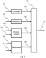
- Fig. 1 shows a schematic representation of an observer model 1 for determining a local car speed v car using a method according to a first embodiment of the invention.
- control engineering observer model 1 functioning as a simulation model of a system of a chassis unit, in particular a bogie of a wagon of a rail vehicle, into which measurement results from sensors 3 arranged on the chassis unit or the bogie ( Fig. 6 ) as output variables of the system as input variables, state variables are determined.
- the system can also be one of the carriages of the rail vehicle, in which case the sensors 3 are not necessarily arranged on the chassis unit or the bogie, but are provided at a suitable location on the carriage.
- the state variables can, for example, be more precise or corrected measurement results from sensors 3. Furthermore, hidden state variables can also be determined that cannot be measured or can only be measured with great effort.
- the state variables are determined using equations, in particular differential equations, which define a behavior of the state variables in relation to respective input variables, but also a behavior of the state variables in relation to one another. This means that even in the case of individual inaccurate or incorrect measurement results, precise state variables can be determined by taking several relevant measurement results into account using sensor fusion.
- the observer model 1 can optionally contain a Kalman filter 2 ( Fig. 2 ), who can also estimate his own errors in determining the state variables.
- a Kalman filter 2 Fig. 2
- the input variables include a longitudinal acceleration a x,mess of the car recorded by an acceleration sensor and a wheel speed or angular velocity ⁇ axis of an axle of the wheel.
- a speed n especially a wheel speed n wheel or a Wheel speed v Odo , which was determined, for example, from the wheel speed n Rad and the wheel radius, must be entered.
- One state variable that is determined in the observer is the local car speed v car .
- other state variables such as an acceleration or a drift d, can be determined and output if necessary.
- the carriage has a longitudinal direction and has an acceleration sensor that detects an acceleration a z,mess in a direction perpendicular to the longitudinal direction in a vertical plane.
- the speed-relevant sensor data available locally in the car is recorded as the respective input variable for the observer model 1 and entered into the observer model 1.
- the sensor data contains the data from the acceleration sensor for the longitudinal acceleration a x,mess of the car and the wheel speed or angular velocity ⁇ axis of the wheel axle.
- the observer model 1 continuously observes the state of the input variables and determines the state variable, namely the local car speed v car . Continuous in this context means that there is no switching between different operating modes, in which different input variables are evaluated.
- other speed-relevant sensor data such as data from a positioning system, e.g. using a satellite navigation system, brake pressures or supply voltages or supply currents from drive motors, are provided.
- the speed-relevant sensor data is recorded by the sensors arranged on the chassis unit or the bogie.
- the sensor data is recorded by sensors arranged at the appropriate location on the wagon.
- Sensor data can also be recorded from sensors other than the acceleration sensor and a pulse generator for the wheel speed or the angular velocity of the axle.
- An acceleration a z,mess in a direction perpendicular to the longitudinal direction of the carriage in a vertical plane is detected, and the acceleration sensor data for the acceleration a x,mess in the longitudinal direction are corrected by the acceleration a z,mess in the vertical plane perpendicular to the longitudinal direction and input.
- the data for the acceleration a x,mess in the longitudinal direction are not corrected by the acceleration a z,mess in the vertical plane perpendicular to the longitudinal direction, but the acceleration a z,mess perpendicular to the longitudinal direction of the carriage in the vertical plane is an input of the observer model.
- the rotation of the coordinate system of the vehicle by the angle of the gradient and inclination of the height profile and thus the correction value of the driving speed to be determined in the vehicle's longitudinal plane can also be determined by other methods.
- Fig. 2 shows a schematic representation of an observer model as a Kalman filter 2 for determining the local car speed v car using a method according to a second embodiment of the invention.
- the observer model in the second embodiment differs from the observer model 1 in the first embodiment in that it is necessarily a Kalman filter 2 or a control-engineering observer model that contains a functionality of the Kalman filter and that is designed as a control-engineering observer model specialized for an acceleration and braking process.
- a speed of the car v car an acceleration of the car and a drift, namely a systematic deviation of a measured acceleration from an acceleration related to a movement of the vehicle mass of the car, are determined as state variables, which leads to an accurate observation of the actual driving speed.
- the speed-relevant sensor data contain measurement results of a wheel speed sensor ⁇ axis , and a variance Var(X,t) of a measurement noise of the state variable speed is variably adapted over time.
- a value of the variance Var(x,t) is adjusted proportionally to a difference between a requested and actually realized braking or driving value or proportionally to a factor determined from at least one of the requested and actually realized braking and driving values as explained above.
- Fig. 3 shows a schematic representation of the observer model 1 for determining the local car speed v car using a method according to a third embodiment of the invention.
- the method according to the third embodiment differs from the method according to the first embodiment in that a vehicle inclination ⁇ about a horizontal axis perpendicular to the longitudinal axis of the vehicle is one of the state variables, and measurement variables required for determining the vehicle inclination are entered as input variables.
- the measurement quantity required to determine the vehicle inclination ⁇ in addition to the acceleration a x,mess in the longitudinal direction is an acceleration a z,mess in a vertical direction perpendicular to the longitudinal direction in order to determine the vehicle inclination ⁇ .
- suitable measurement quantities can be used to determine the vehicle inclination, for example a measurement result from a gyroscope or inclinometer or by combining a known topography of a section of road with a position determination method, for example by comparing the current position with digital map material.
- Fig. 4 shows a schematic representation of the observer model 1 for determining the local car speed v car using a method according to a fourth embodiment of the invention.
- the method according to the fourth embodiment differs from the methods according to the first or third embodiment in that the input variables additionally contain measurable forces F x introduced into the carriage from the outside.
- Fig. 5 shows a schematic representation of an observer model 1, 2 for a method according to the invention with a sensor data fusion for individual local car speeds v car,i to v car,n of a train for determining a train speed v train .
- a plurality of local car speeds v car,i to v car,n of the cars of the train determined according to a method of the previous embodiments are averaged by the observer model 1, 2 to determine the train speed v train .
- the observer model 1, 2 for sensor data fusion is, for example, a conventional observer model 1, but can optionally also be a Kalman filter 2. However, it can also be designed as a simple arithmetic average.
- a diagnostic function is performed by checking the plausibility of the individual local car speeds v car, i . Implausible local Car speeds v car , i are ignored for determining the train speed v train .
- a Kalman filter 2 is used as the observer model for determining the local car speeds v car,i to v car,n .
- These Kalman filters 2 each determine a variance of a measurement noise Var car,i ( ⁇ ,t) to Var car,n ( ⁇ ,t) as a measure of confidence for checking the plausibility of the state variable of the local car speed v car,i to v car en,n of the individual cars.
- the variance of the respective measurement noise Var car,i ( ⁇ ,t) for the individual local car speeds v car is entered as an input variable into the control engineering observer model 1, 2 for sensor data fusion for individual local car speeds v car,i to v car en,n. If a minimum level of confidence in one of the local car speeds v car is undercut, an associated wheel speed is devalued accordingly or not taken into account as an input variable in the Kalman filter 2.
- the train speed determined by the observer model 1, 2 for sensor data fusion for individual local car speeds v car,i to v car,n is compared with a train speed calculated from other sources in order to implement further diagnostic functions and corrective measures.
- a vehicle speed v location determined by means of a positioning system e.g. by means of a satellite navigation system, is entered into the observer model 1, 2 for sensor data fusion for individual local car speeds v car,i to v car ,n.
- Fig. 6 shows a schematic diagram of a structure for the method according to the second embodiment of the invention.
- Sensors 3 record the respective measurement results, for example the longitudinal acceleration, the impulses or forces, and enter any erroneous measurement signals as input variables into the Kalman filter 2.
- the erroneous measurement results are processed using the simulation model and precise output signals are determined. These precise Output signals are then provided for and processed by optimized algorithms in railway operations, such as wheel slide protection or inclination detection.
- a wheel diameter is defined as another state variable, with little process noise since the wheel diameter is approximately constant.
- Slip in a wheel-rail contact is defined as another state variable.
- the pulse generator measures a difference between the speed and the slip. A very precise calculation of a momentary slip is possible, especially in conjunction with an accurate position measurement.
- a gradient or a gradient are not known in advance, but are determined as an additional disturbance from the Kalman filter 2.
- the acceleration is fused from a position signal and a speed signal.
- a simplified 2D simulation model of a car body, the bogie and the wheel sets is integrated into the Kalman filter 2 with slip as one of the state variables. This allows a wheel contact force to be defined as one of the state variables.
- each observer model can be designed to determine at least one of the states speed, acceleration, drift size and gradient value.
- Fig. 7 shows a diagram of a calculation of a quality of wheel speed.
- a calculation block B is shown which is designed to determine a quality Q of the wheel speed v Odo on the basis of input values Q1, Q2, Q3, Q4 which lead into the calculation block B on the left.
- the calculation block B finally outputs the quality Q of the wheel speed v Odo on its right-hand side.
- the input value Q1 comes from a calculation block that represents a basic value calculation. Based on one or more parameters P1 that result from the operation of the vehicle, a basic value for the quality Q is calculated here, which is then transmitted to the calculation block B as input value Q1.
- a parameter P1 can simply be information about whether a brake intervention is taking place, whether the corresponding wheel is being driven, or whether it is torque-free.
- Another input value Q2 comes from a calculation block that specifically processes parameter P2 from the car's anti-skid function. If, for example, the car's anti-skid function is triggered, the input value Q2 is changed accordingly, so that the calculation block B then outputs a characteristic value that corresponds to a poorer quality Q.
- Another input value Q3 comes from a calculation block that processes the wheel speed v Odo and a reference speed v Ref as input variables. For example, a minimum slip can be determined from the comparison of the wheel speed v Odo with the reference speed v Ref , which would occur in comparison to the car with zero slip and with ideal power transmission between wheel and rail. Such a minimum slip can then be given as input value Q3 in calculation block B, for example.
- the input value Q3 can also be an abstract value.
- Another input value Q4 comes from a calculation block that evaluates moments and/or forces on the wheel and uses them to determine the input value Q4.
- the quantities M and P are used as input quantities.
- M represents a quantity that corresponds to a drive torque acting on the wheel, or a quantity from which the drive torque of the wheel can be determined.
- this can be a current of an electric motor.
- the quantity P represents a quantity that corresponds to a braking torque acting on the wheel, or a quantity from which the braking torque of the wheel can be determined.
- this can be a current of an eddy current brake, a brake pressure or something similar.
- a force between the rail and the wheel which corresponds to a drive or braking force, can also be determined. If the quantities M, P are relatively high, an input value Q4 can be determined, which causes a lower quality Q to be calculated in calculation block B, compared to a state with lower quantities M, P.
- the calculation block B is designed as an addition operator which adds the input values Q1, Q2, Q3, Q4 and thereby forms the quality Q as a sum.
- the processing of the input values Q1, Q2, Q3, Q4 can also be weighted.
Landscapes
- Engineering & Computer Science (AREA)
- Mechanical Engineering (AREA)
- Transportation (AREA)
- Physics & Mathematics (AREA)
- Automation & Control Theory (AREA)
- Mathematical Physics (AREA)
- General Physics & Mathematics (AREA)
- Electric Propulsion And Braking For Vehicles (AREA)
- Control Of Driving Devices And Active Controlling Of Vehicle (AREA)
- Regulating Braking Force (AREA)
Claims (20)
- Procédé de détermination d'une vitesse de voiture (vVoiture) d'une voiture avec les étapes consistant à :- acquérir de données de capteur disponibles dans la voiture comme grandeur d'entrée respective pour un modèle d'observateur (1, 2) ;- introduire des grandeurs d'entrée dans le modèle d'observateur (1, 2) ;- mettre en oeuvre d'une détermination continue de la vitesse de voiture (vVoiture) par le modèle d'observateur (1, 2),caractérisé en ce que
le modèle d'observateur (1, 2) détermine une grandeur de dérive (d) qui est déterminée comme grandeur d'état du modèle d'observateur (1, 2), et dans lequel la grandeur de dérive (d) est définie comme montant d'une- différence entre une accélération longitudinale réelle (ax) de la voiture et une accélération longitudinale mesurée (ax,mesurée), et/ou- différence entre une accélération longitudinale qui est déterminée à partir d'une vitesse de rotation (n), de préférence à partir d'une vitesse de rotation de roue (nRoue), et l'accélération longitudinale mesurée (ax,mesurée), et/ou- différence entre l'accélération longitudinale qui est déterminée à partir de la vitesse de rotation (n), de préférence à partir de la vitesse de rotation de roue (nRoue), et l'accélération longitudinale réelle (ax). - Procédé selon la revendication 1, dans lequelles données de capteur contiennent l'accélération longitudinale mesurée (ax,mesurée) de la voiture et/ou la vitesse de rotation (n) d'un élément de voiture dont la vitesse de rotation (n) est proportionnelle à la vitesse de rotation de roue (nRoue), et/ou dans lequelles grandeurs d'entrée contiennent des forces (Fx) mesurables ou, de préférence au moyen d'un modèle d'observateur, déterminées indirectement par le système de freinage ou d'entraînement de la voiture.
- Procédé selon la revendication 1 ou 2, dans lequel
le modèle d'observateur (1, 2) utilise une vitesse et une accélération de la voiture comme grandeurs d'état, dans lequel la vitesse est de préférence la vitesse de voiture déterminée (vVoiture) et/ou l'accélération est une accélération longitudinale de la voiture. - Procédé selon l'une quelconque des revendications précédentes, dans lequel
au moins une partie des données de capteur est acquise par des capteurs disposés sur une unité de châssis, en particulier un bogie. - Procédé selon l'une quelconque des revendications précédentes, dans lequel
les données de capteur contiennent des valeurs de mesure, en particulier relatives à la vitesse,- d'un capteur d'accélération,- d'un capteur d'inclinaison- d'une unité de mesure inertielle,- d'un capteur de vitesse de rotation,- d'un capteur de pression de freinage,- d'un capteur de courant de freinage, et/ou- d'un moteur. - Procédé selon l'une quelconque des revendications précédentes, dans lequel
une dynamique de dérive est déterminée par la détermination d'un taux de variation dans le temps de la grandeur de dérive (d), de préférence par le modèle d'observateur (1, 2), dans lequel la valeur de la dynamique de dérive est de préférence comparé à des valeurs maximales prédéterminées et, plus préférentiellement lorsque les valeurs maximales prédéterminées sont dépassées par la valeur de la dynamique de dérive, un processus de mise à disposition erroné de la vitesse de rotation (n), en particulier de la vitesse de rotation de roue (nRoue), est déduit, et les valeurs maximales prédéterminées contiennent de préférence des variations de pente et d'inclinaison sur un parcours, des erreurs de montage et de calibrage des capteurs d'accélération utilisés et des dynamiques d'accélération et de décélération habituelles du train. - Procédé selon l'une quelconque des revendications précédentes, dans lequel
une pondération d'au moins une des grandeurs d'entrée est continuellement effectuée sur la base d'un critère d'évaluation pour adapter l'influence de cette grandeur d'entrée dans le modèle d'observateur (1, 2). - Procédé selon l'une quelconque des revendications précédentes, dans lequelun filtre de Kalman (2) est utilisé comme modèle d'observateur (1, 2), etde préférence une variance d'un bruit de mesure d'au moins une des grandeurs d'entrée est adaptée à une grandeur d'entrée du modèle d'observateur (1, 2).
- Procédé selon la revendication 7 ou 8, dans lequel
l'adaptation de la valeur de la variance du bruit de mesure d'au moins une des grandeurs d'entrée ou la pondération d'au moins une des grandeurs d'entrée est effectuée en fonction d'un paramètre qui résulte de processus d'entraînement et/ou de freinage de la voiture. - Procédé selon l'une quelconque des revendications précédentes, dans lequel
une des grandeurs d'entrée du modèle d'observateur (1, 2) est la vitesse de rotation de roue (nRoue) ou est déterminée à partir d'une vitesse de rotation de roue (nRoue), dans lequel une vitesse de roue (vOdo) est de préférence déterminée à partir de la vitesse de rotation de roue (nRoue) et la vitesse de roue (vOdo) est le plus préférentiellement également une des grandeurs d'entrée du modèle d'observateur (1, 2). - Procédé selon l'une quelconque des revendications précédentes avec les caractéristiques selon la revendication 2, dans lequel
une valeur de pente (a) est déterminée, qui représente de préférence une des grandeurs d'entrée du modèle d'observateur (1, 2), dans lequel la valeur de pente (α) est de préférence mesurée et/ou estimée et/ou déterminée à partir d'une base de données, dans lequel la valeur de pente (a) est le plus préférentiellement utilisée pour la correction de l'accélération longitudinale (ax,mesurée) mesurée. - Procédé selon l'une quelconque des revendications précédentes, dans lequella voiture présente une direction longitudinale et une accélération verticale (az,mesurée) est acquise dans une direction verticale de la voiture perpendiculaire à la direction longitudinale dans un plan vertical, et l'accélération longitudinale mesurée (ax,mesurée) est corrigée par l'accélération verticale (az,mesurée) et/ou l'accélération verticale (az,mesurée) est une grandeur d'entrée du modèle d'observateur (1, 2), dans lequel une correction de l'accélération longitudinale (ax,mesurée) par l'accélération verticale (az,mesurée) est de préférence effectuée dans le modèle d'observateur (1, 2) et/ou dans lequelune inclinaison de véhicule autour d'un axe horizontal perpendiculaire à l'axe longitudinal et perpendiculaire à l'axe vertical est utilisée comme une des grandeurs d'état du modèle d'observateur (1, 2), etdes grandeurs de mesure nécessaires pour une détermination de l'inclinaison de véhicule sont entrées comme grandeurs d'entrée dans le modèle d'observateur (1, 2), dans lequel l'accélération verticale (az,mesurée) est entrée en particulier.
- Procédé selon l'une quelconque des revendications 10 à 12, présentant une étape supplémentaire consistant à :- déterminer une qualité de la vitesse de roue déterminée (vOdo), dans lequella qualité est de préférence formée comme valeur caractéristique en tenant compte au moins d'une des grandeurs suivantes :- une pression de freinage et/ou une force de serrage d'un frein qui est conçu pour le freinage de la roue ;- un courant et/ou une tension d'un dispositif qui est conçu pour appliquer un couple à la roue ;- un couple d'entraînement ou de freinage appliqué à la roue ;- une force de poids de la voiture qui est déterminée par une détection de charge- un patinage de roue de la roue ;- une vitesse de référence (vRéf) et/ou la vitesse de la voiture (Vvoiture) ;- un coefficient de frottement entre la roue et une surface sur laquelle la roue roule ;- l'accélération détectée (amesurée) ;- un couple d'entraînement ou de freinage appliqué à la roue ;- une vitesse de véhicule globale ;- une information sur l'application ou non d'une protection antidérapante ;- une information sur l'application ou non d'un freinage ;- une information sur l'entraînement ou non de la roue correspondante.
- Procédé selon la revendication 13, dans lequel
la variance du bruit de mesure d'au moins une des grandeurs d'entrée et/ou la pondération d'au moins une des grandeurs d'entrée est influencée par la qualité, en particulier par la valeur caractéristique, qui dépasse ou n'atteint pas une valeur limite. - Procédé de détermination d'une vitesse de train (VTrain) avec l'étape consistant à :- déterminer au moins une vitesse de voiture (vVoiture) d'une voiture qui appartient à un train avec au moins une voiture selon le procédé d'une des revendications 1 à 14, et- déterminer une vitesse de train (VTrain) à partir de la au moins une vitesse de voiture (vVoiture), de préférence en faisant la moyenne de la au moins une vitesse de voiture (VVoiture) ;- de préférence effectuer un contrôle de plausibilité de la au moins une vitesse de voiture (vVoiture) ; et- de préférence ignorer les vitesses de voiture (vVoiture) non plausibles pour la détermination de la vitesse de train (vTrain), et/ou- de préférence ignorer les vitesses de voiture (vVoiture) qui sont déterminées sur la base de vitesses de roue (vOdo) avec une qualité qui se situe sous un niveau de qualité prédéterminé.
- Procédé selon la revendication 15, dans lequelun filtre de Kalman est utilisé comme modèle d'observateur pour déterminer la vitesse de voiture (vVoiture) locale,une variance (Varvoiture,i(x,t)) d'un bruit de mesure dans le filtre de Kalman est déterminée comme mesure d'une confiance pour le contrôle de la plausibilité de la vitesse de voiture (vVoiture) locale, etsi une mesure minimale de la confiance accordée à une des vitesses de voiture (vVoiture) locales n'est pas atteinte, la vitesse de rotation de roue (nRoue) correspondante ou la vitesse de roue (vOdo) correspondante est ignorée comme grandeur d'entrée.
- Procédé selon l'une quelconque des revendications 15 ou 16, avec l'étape consistant à :- comparer ou corriger la vitesse de train (VTrain) déterminée à une vitesse de train (VTrain) formée à partir d'autres sources, dans lequelune autre source est de préférence une mesure radar ou une mesure GPS, dans lequella comparaison ou la correction s'effectue de préférence par fusion en utilisant un filtre de Kalman.
- Dispositif pour déterminer une vitesse de voiture (vVoiture) ou une vitesse de train (VTrain) qui est conçu pour mettre en oeuvre le procédé selon l'une quelconque des revendications 1à 17.
- Véhicule, en particulier véhicule ferroviaire, en particulier présentant au moins une voiture, dans lequel le véhicule est conçu pour mettre en oeuvre le procédé selon l'une quelconque des revendications 1 à 17, et/ou le véhicule présente un dispositif selon la revendication 18.
- Produit de programme informatique avec des moyens de code qui sont stockés sur un support lisible par machine et qui amènent un dispositif de traitement de données, de préférence un dispositif selon la revendication 18, à mettre en oeuvre le procédé selon l'une quelconque des revendications 1 à 17 lorsque les moyens de code sont exécutés sur le dispositif de traitement de données.
Applications Claiming Priority (2)
| Application Number | Priority Date | Filing Date | Title |
|---|---|---|---|
| DE102019211944.1A DE102019211944A1 (de) | 2019-08-08 | 2019-08-08 | Verfahren zur Bestimmung einer lokalen Wagengeschwindigkeit eines Wagens |
| PCT/EP2020/071278 WO2021023584A1 (fr) | 2019-08-08 | 2020-07-28 | Procédé de détermination d'une vitesse locale d'une voiture |
Publications (2)
| Publication Number | Publication Date |
|---|---|
| EP4010234A1 EP4010234A1 (fr) | 2022-06-15 |
| EP4010234B1 true EP4010234B1 (fr) | 2024-10-30 |
Family
ID=71894794
Family Applications (1)
| Application Number | Title | Priority Date | Filing Date |
|---|---|---|---|
| EP20749841.1A Active EP4010234B1 (fr) | 2019-08-08 | 2020-07-28 | Procédé de détermination d'une vitesse locale d'une voiture |
Country Status (4)
| Country | Link |
|---|---|
| EP (1) | EP4010234B1 (fr) |
| DE (1) | DE102019211944A1 (fr) |
| ES (1) | ES3004657T3 (fr) |
| WO (1) | WO2021023584A1 (fr) |
Families Citing this family (5)
| Publication number | Priority date | Publication date | Assignee | Title |
|---|---|---|---|---|
| DE102022206618A1 (de) * | 2022-06-29 | 2024-01-04 | Siemens Mobility GmbH | Schätzeinrichtung und Verfahren zum Ermitteln von Bewegungsschätzwerten |
| DE102022208176A1 (de) * | 2022-08-05 | 2024-02-08 | Robert Bosch Gesellschaft mit beschränkter Haftung | Verfahren zum Auswerten von Sensordaten, Recheneinheit zum Auswerten von Sensordaten und Sensorsystem, Verfahren zum Herstellen eines Sensorsystems |
| DE102022210315A1 (de) * | 2022-09-29 | 2024-04-04 | Siemens Mobility GmbH | Schätzeinrichtung |
| CN116373815A (zh) * | 2023-05-04 | 2023-07-04 | 青岛建邦汽车科技股份有限公司 | 一种后加装拖车同步制动方法和装置 |
| DE102024203774A1 (de) * | 2024-04-23 | 2025-10-23 | Robert Bosch Gesellschaft mit beschränkter Haftung | Verfahren zur Durchführung einer hochgenauen Geschwindigkeitsbestimmung in einem Kraftfahrzeug mit Hilfe eines Kalman-Filters |
Family Cites Families (8)
| Publication number | Priority date | Publication date | Assignee | Title |
|---|---|---|---|---|
| DE4104775A1 (de) * | 1991-02-13 | 1992-08-20 | Knorr Bremse Berlin Ag | Verfahren zur ermittlung der geschwindigkeit eines fahrzeuges mit schlupfgeregelten raedern |
| JP3166446B2 (ja) * | 1993-10-26 | 2001-05-14 | 株式会社明電舎 | 速度推定オブザーバ |
| FR2817527B1 (fr) * | 2000-12-04 | 2003-01-10 | Alstom | Procede et dispositif de localisation d'un vehicule sur une voie |
| US6816804B1 (en) * | 2003-06-04 | 2004-11-09 | Visteon Global Technologies, Inc. | System and method for estimating velocity using reliability indexed sensor fusion |
| DE102013210361A1 (de) * | 2013-06-04 | 2014-12-04 | Siemens Aktiengesellschaft | Verfahren zur Ermittlung zumindest einer Geschwindigkeit bei einem Schienenfahrzeug |
| KR101583878B1 (ko) * | 2013-11-15 | 2016-01-08 | 엘에스산전 주식회사 | 열차속도 제어장치 |
| DE102017213806A1 (de) * | 2017-08-08 | 2019-02-14 | Siemens Aktiengesellschaft | Kalibration von Fahrzeugsensoren |
| DE102017213970A1 (de) * | 2017-08-10 | 2019-02-14 | Deutsches Zentrum für Luft- und Raumfahrt e.V. | Verfahren und Vorrichtung zum Bestimmen von Veränderungen im längsdynamischen Verhalten eines Schienenfahrzeugs |
-
2019
- 2019-08-08 DE DE102019211944.1A patent/DE102019211944A1/de active Pending
-
2020
- 2020-07-28 ES ES20749841T patent/ES3004657T3/es active Active
- 2020-07-28 WO PCT/EP2020/071278 patent/WO2021023584A1/fr not_active Ceased
- 2020-07-28 EP EP20749841.1A patent/EP4010234B1/fr active Active
Also Published As
| Publication number | Publication date |
|---|---|
| ES3004657T3 (en) | 2025-03-12 |
| EP4010234A1 (fr) | 2022-06-15 |
| DE102019211944A1 (de) | 2021-02-11 |
| WO2021023584A1 (fr) | 2021-02-11 |
Similar Documents
| Publication | Publication Date | Title |
|---|---|---|
| EP4010234B1 (fr) | Procédé de détermination d'une vitesse locale d'une voiture | |
| EP3717283B1 (fr) | Méthode, dispisitif et système d' évaluation de la profondeur des sculptures d'un pneumatique | |
| EP2755868B1 (fr) | Système capteur comportant une unité de modèle de véhicule | |
| EP2771714B1 (fr) | Système de détection conçu pour une autoévaluation de l'intégrité de ses données | |
| EP1430276B1 (fr) | Procede de determination de la masse d'un vehicule avec prise en compte de differentes situations de conduite | |
| DE602004003387T2 (de) | Verfahren und einrichtung zur schätzung der gesamtmasse eines kraftfahrzeugs | |
| EP2981832B1 (fr) | Procédé de détermination d'au moins une vitesse d'un véhicule ferroviaire | |
| DE102019211939B4 (de) | Verfahren zur Bestimmung einer Wagengeschwindigkeit eines Wagens | |
| EP0938987B1 (fr) | Méthode et appareil de surveillance de la pression des pneumatiques d'un véhicule automobile | |
| EP3027436B1 (fr) | Procédé et système de détermination d'un rapport de pression entre une pression de gonflage idéale et une pression de gonflage effective pour un pneu d'un véhicule | |
| DE102007002791A1 (de) | Verfahren und Vorrichtung zur Bestimmung der Geschwindigkeit eines Fahrzeugs | |
| DE102016223902B4 (de) | Verfahren und System zur Bestimmung von Radumfängen und Spurweiten eines Fahrzeugs | |
| EP4034443B1 (fr) | Procédé de détermination d'une circonférence de roue de véhicule et véhicule à moteur | |
| EP1387153A1 (fr) | Procédé et dispositif pour la détermination de la masse d'un véhicule | |
| EP3789264B1 (fr) | Procédé et dispositif par la detection de glissement et véhicule ferroviaire | |
| EP3552920A1 (fr) | Détection et élimination des états de glissement et de patinage des véhicules ferroviaires | |
| DE102019211934B4 (de) | Verfahren zur Bestimmung einer Zuggeschwindigkeit eines Zugs mit mindestens einem Wagen | |
| EP2225568B1 (fr) | Procede et dispositif d'identification du sens de deplacement d'un vehicule | |
| EP3927593B1 (fr) | Procédé de détection d'écarts systématiques lors de la détermination d'une grandeur de mouvement d'un véhicule terrestre, en particulier d'un véhicule ferroviaire, et appareil et véhicule associés | |
| DE102017222324A1 (de) | Verfahren und Vorrichtung zum Ermitteln eines Verschleißzustandes von Rädern eines Schienenfahrzeugs | |
| DE19802498B4 (de) | Verfahren und Vorrichtung zur Reifendrucküberwachung | |
| WO2005123423A2 (fr) | Systeme de detection d'une chute de pression sur le pneu d'un vehicule | |
| DE102021201230A1 (de) | Verfahren und Vorrichtung zum Schätzen eines Rollradius eines Rads eines Fahrzeugs | |
| DE10242123A1 (de) | Fahrdynamikregelungssystem mit Steilkurvenerkennung | |
| DE102015220067B3 (de) | Verfahren zur Bestimmung einer Einbaulage eines Gyroskops in einem Kraftfahrzeug |
Legal Events
| Date | Code | Title | Description |
|---|---|---|---|
| STAA | Information on the status of an ep patent application or granted ep patent |
Free format text: STATUS: UNKNOWN |
|
| STAA | Information on the status of an ep patent application or granted ep patent |
Free format text: STATUS: THE INTERNATIONAL PUBLICATION HAS BEEN MADE |
|
| PUAI | Public reference made under article 153(3) epc to a published international application that has entered the european phase |
Free format text: ORIGINAL CODE: 0009012 |
|
| STAA | Information on the status of an ep patent application or granted ep patent |
Free format text: STATUS: REQUEST FOR EXAMINATION WAS MADE |
|
| 17P | Request for examination filed |
Effective date: 20220309 |
|
| AK | Designated contracting states |
Kind code of ref document: A1 Designated state(s): AL AT BE BG CH CY CZ DE DK EE ES FI FR GB GR HR HU IE IS IT LI LT LU LV MC MK MT NL NO PL PT RO RS SE SI SK SM TR |
|
| DAV | Request for validation of the european patent (deleted) | ||
| DAX | Request for extension of the european patent (deleted) | ||
| GRAP | Despatch of communication of intention to grant a patent |
Free format text: ORIGINAL CODE: EPIDOSNIGR1 |
|
| STAA | Information on the status of an ep patent application or granted ep patent |
Free format text: STATUS: GRANT OF PATENT IS INTENDED |
|
| RIC1 | Information provided on ipc code assigned before grant |
Ipc: B60W 40/105 20120101ALI20240628BHEP Ipc: B60T 8/172 20060101ALI20240628BHEP Ipc: B60T 8/17 20060101ALI20240628BHEP Ipc: G01P 3/50 20060101ALI20240628BHEP Ipc: B61L 25/02 20060101AFI20240628BHEP |
|
| INTG | Intention to grant announced |
Effective date: 20240710 |
|
| GRAS | Grant fee paid |
Free format text: ORIGINAL CODE: EPIDOSNIGR3 |
|
| GRAA | (expected) grant |
Free format text: ORIGINAL CODE: 0009210 |
|
| STAA | Information on the status of an ep patent application or granted ep patent |
Free format text: STATUS: THE PATENT HAS BEEN GRANTED |
|
| AK | Designated contracting states |
Kind code of ref document: B1 Designated state(s): AL AT BE BG CH CY CZ DE DK EE ES FI FR GB GR HR HU IE IS IT LI LT LU LV MC MK MT NL NO PL PT RO RS SE SI SK SM TR |
|
| REG | Reference to a national code |
Ref country code: GB Ref legal event code: FG4D Free format text: NOT ENGLISH |
|
| REG | Reference to a national code |
Ref country code: CH Ref legal event code: EP |
|
| REG | Reference to a national code |
Ref country code: IE Ref legal event code: FG4D Free format text: LANGUAGE OF EP DOCUMENT: GERMAN |
|
| REG | Reference to a national code |
Ref country code: DE Ref legal event code: R096 Ref document number: 502020009636 Country of ref document: DE |
|
| REG | Reference to a national code |
Ref country code: SE Ref legal event code: TRGR |
|
| P01 | Opt-out of the competence of the unified patent court (upc) registered |
Free format text: CASE NUMBER: APP_66730/2024 Effective date: 20241217 |
|
| REG | Reference to a national code |
Ref country code: LT Ref legal event code: MG9D |
|
| REG | Reference to a national code |
Ref country code: NL Ref legal event code: MP Effective date: 20241030 |
|
| REG | Reference to a national code |
Ref country code: ES Ref legal event code: FG2A Ref document number: 3004657 Country of ref document: ES Kind code of ref document: T3 Effective date: 20250312 |
|
| PG25 | Lapsed in a contracting state [announced via postgrant information from national office to epo] |
Ref country code: PT Free format text: LAPSE BECAUSE OF FAILURE TO SUBMIT A TRANSLATION OF THE DESCRIPTION OR TO PAY THE FEE WITHIN THE PRESCRIBED TIME-LIMIT Effective date: 20250228 Ref country code: IS Free format text: LAPSE BECAUSE OF FAILURE TO SUBMIT A TRANSLATION OF THE DESCRIPTION OR TO PAY THE FEE WITHIN THE PRESCRIBED TIME-LIMIT Effective date: 20250228 Ref country code: HR Free format text: LAPSE BECAUSE OF FAILURE TO SUBMIT A TRANSLATION OF THE DESCRIPTION OR TO PAY THE FEE WITHIN THE PRESCRIBED TIME-LIMIT Effective date: 20241030 |
|
| PG25 | Lapsed in a contracting state [announced via postgrant information from national office to epo] |
Ref country code: FI Free format text: LAPSE BECAUSE OF FAILURE TO SUBMIT A TRANSLATION OF THE DESCRIPTION OR TO PAY THE FEE WITHIN THE PRESCRIBED TIME-LIMIT Effective date: 20241030 Ref country code: NL Free format text: LAPSE BECAUSE OF FAILURE TO SUBMIT A TRANSLATION OF THE DESCRIPTION OR TO PAY THE FEE WITHIN THE PRESCRIBED TIME-LIMIT Effective date: 20241030 |
|
| PG25 | Lapsed in a contracting state [announced via postgrant information from national office to epo] |
Ref country code: BG Free format text: LAPSE BECAUSE OF FAILURE TO SUBMIT A TRANSLATION OF THE DESCRIPTION OR TO PAY THE FEE WITHIN THE PRESCRIBED TIME-LIMIT Effective date: 20241030 |
|
| PG25 | Lapsed in a contracting state [announced via postgrant information from national office to epo] |
Ref country code: NO Free format text: LAPSE BECAUSE OF FAILURE TO SUBMIT A TRANSLATION OF THE DESCRIPTION OR TO PAY THE FEE WITHIN THE PRESCRIBED TIME-LIMIT Effective date: 20250130 |
|
| PG25 | Lapsed in a contracting state [announced via postgrant information from national office to epo] |
Ref country code: LV Free format text: LAPSE BECAUSE OF FAILURE TO SUBMIT A TRANSLATION OF THE DESCRIPTION OR TO PAY THE FEE WITHIN THE PRESCRIBED TIME-LIMIT Effective date: 20241030 Ref country code: GR Free format text: LAPSE BECAUSE OF FAILURE TO SUBMIT A TRANSLATION OF THE DESCRIPTION OR TO PAY THE FEE WITHIN THE PRESCRIBED TIME-LIMIT Effective date: 20250131 |
|
| PG25 | Lapsed in a contracting state [announced via postgrant information from national office to epo] |
Ref country code: PL Free format text: LAPSE BECAUSE OF FAILURE TO SUBMIT A TRANSLATION OF THE DESCRIPTION OR TO PAY THE FEE WITHIN THE PRESCRIBED TIME-LIMIT Effective date: 20241030 |
|
| PG25 | Lapsed in a contracting state [announced via postgrant information from national office to epo] |
Ref country code: RS Free format text: LAPSE BECAUSE OF FAILURE TO SUBMIT A TRANSLATION OF THE DESCRIPTION OR TO PAY THE FEE WITHIN THE PRESCRIBED TIME-LIMIT Effective date: 20250130 |
|
| PG25 | Lapsed in a contracting state [announced via postgrant information from national office to epo] |
Ref country code: SM Free format text: LAPSE BECAUSE OF FAILURE TO SUBMIT A TRANSLATION OF THE DESCRIPTION OR TO PAY THE FEE WITHIN THE PRESCRIBED TIME-LIMIT Effective date: 20241030 |
|
| PG25 | Lapsed in a contracting state [announced via postgrant information from national office to epo] |
Ref country code: DK Free format text: LAPSE BECAUSE OF FAILURE TO SUBMIT A TRANSLATION OF THE DESCRIPTION OR TO PAY THE FEE WITHIN THE PRESCRIBED TIME-LIMIT Effective date: 20241030 |
|
| PG25 | Lapsed in a contracting state [announced via postgrant information from national office to epo] |
Ref country code: EE Free format text: LAPSE BECAUSE OF FAILURE TO SUBMIT A TRANSLATION OF THE DESCRIPTION OR TO PAY THE FEE WITHIN THE PRESCRIBED TIME-LIMIT Effective date: 20241030 |
|
| PG25 | Lapsed in a contracting state [announced via postgrant information from national office to epo] |
Ref country code: RO Free format text: LAPSE BECAUSE OF FAILURE TO SUBMIT A TRANSLATION OF THE DESCRIPTION OR TO PAY THE FEE WITHIN THE PRESCRIBED TIME-LIMIT Effective date: 20241030 |
|
| PG25 | Lapsed in a contracting state [announced via postgrant information from national office to epo] |
Ref country code: SK Free format text: LAPSE BECAUSE OF FAILURE TO SUBMIT A TRANSLATION OF THE DESCRIPTION OR TO PAY THE FEE WITHIN THE PRESCRIBED TIME-LIMIT Effective date: 20241030 |
|
| PG25 | Lapsed in a contracting state [announced via postgrant information from national office to epo] |
Ref country code: CZ Free format text: LAPSE BECAUSE OF FAILURE TO SUBMIT A TRANSLATION OF THE DESCRIPTION OR TO PAY THE FEE WITHIN THE PRESCRIBED TIME-LIMIT Effective date: 20241030 |
|
| REG | Reference to a national code |
Ref country code: DE Ref legal event code: R097 Ref document number: 502020009636 Country of ref document: DE |
|
| PLBE | No opposition filed within time limit |
Free format text: ORIGINAL CODE: 0009261 |
|
| STAA | Information on the status of an ep patent application or granted ep patent |
Free format text: STATUS: NO OPPOSITION FILED WITHIN TIME LIMIT |
|
| 26N | No opposition filed |
Effective date: 20250731 |
|
| PGFP | Annual fee paid to national office [announced via postgrant information from national office to epo] |
Ref country code: ES Payment date: 20250815 Year of fee payment: 6 |
|
| PGFP | Annual fee paid to national office [announced via postgrant information from national office to epo] |
Ref country code: DE Payment date: 20250724 Year of fee payment: 6 |
|
| PGFP | Annual fee paid to national office [announced via postgrant information from national office to epo] |
Ref country code: IT Payment date: 20250721 Year of fee payment: 6 |
|
| PGFP | Annual fee paid to national office [announced via postgrant information from national office to epo] |
Ref country code: GB Payment date: 20250722 Year of fee payment: 6 |
|
| PGFP | Annual fee paid to national office [announced via postgrant information from national office to epo] |
Ref country code: FR Payment date: 20250724 Year of fee payment: 6 |
|
| PGFP | Annual fee paid to national office [announced via postgrant information from national office to epo] |
Ref country code: SE Payment date: 20250723 Year of fee payment: 6 |
|
| REG | Reference to a national code |
Ref country code: CH Ref legal event code: H13 Free format text: ST27 STATUS EVENT CODE: U-0-0-H10-H13 (AS PROVIDED BY THE NATIONAL OFFICE) Effective date: 20260224 |
|
| PG25 | Lapsed in a contracting state [announced via postgrant information from national office to epo] |
Ref country code: LU Free format text: LAPSE BECAUSE OF NON-PAYMENT OF DUE FEES Effective date: 20250728 |
|
| REG | Reference to a national code |
Ref country code: BE Ref legal event code: MM Effective date: 20250731 |
|
| PG25 | Lapsed in a contracting state [announced via postgrant information from national office to epo] |
Ref country code: BE Free format text: LAPSE BECAUSE OF NON-PAYMENT OF DUE FEES Effective date: 20250731 |