EP4012203A1 - Verriegelungsanordnung und toilette - Google Patents
Verriegelungsanordnung und toilette Download PDFInfo
- Publication number
- EP4012203A1 EP4012203A1 EP21205762.4A EP21205762A EP4012203A1 EP 4012203 A1 EP4012203 A1 EP 4012203A1 EP 21205762 A EP21205762 A EP 21205762A EP 4012203 A1 EP4012203 A1 EP 4012203A1
- Authority
- EP
- European Patent Office
- Prior art keywords
- connecting piece
- flexible connecting
- fixing sheet
- plug
- limiting
- Prior art date
- Legal status (The legal status is an assumption and is not a legal conclusion. Google has not performed a legal analysis and makes no representation as to the accuracy of the status listed.)
- Withdrawn
Links
Images


Classifications
-
- F—MECHANICAL ENGINEERING; LIGHTING; HEATING; WEAPONS; BLASTING
- F16—ENGINEERING ELEMENTS AND UNITS; GENERAL MEASURES FOR PRODUCING AND MAINTAINING EFFECTIVE FUNCTIONING OF MACHINES OR INSTALLATIONS; THERMAL INSULATION IN GENERAL
- F16B—DEVICES FOR FASTENING OR SECURING CONSTRUCTIONAL ELEMENTS OR MACHINE PARTS TOGETHER, e.g. NAILS, BOLTS, CIRCLIPS, CLAMPS, CLIPS OR WEDGES; JOINTS OR JOINTING
- F16B37/00—Nuts or like thread-engaging members
- F16B37/04—Devices for fastening nuts to surfaces, e.g. sheets, plates
- F16B37/041—Releasable devices
-
- A—HUMAN NECESSITIES
- A47—FURNITURE; DOMESTIC ARTICLES OR APPLIANCES; COFFEE MILLS; SPICE MILLS; SUCTION CLEANERS IN GENERAL
- A47K—SANITARY EQUIPMENT; ACCESSORIES THEREFOR, e.g. TOILET ACCESSORIES
- A47K13/00—Seats or covers for all kinds of closets
- A47K13/02—Seats or covers for all kinds of closets of plastic materials
-
- A—HUMAN NECESSITIES
- A47—FURNITURE; DOMESTIC ARTICLES OR APPLIANCES; COFFEE MILLS; SPICE MILLS; SUCTION CLEANERS IN GENERAL
- A47K—SANITARY EQUIPMENT; ACCESSORIES THEREFOR, e.g. TOILET ACCESSORIES
- A47K13/00—Seats or covers for all kinds of closets
- A47K13/10—Devices for raising and lowering ; Collapsible or rotating seats or covers
- A47K13/105—Toilet seat or toilet cover handles
-
- A—HUMAN NECESSITIES
- A47—FURNITURE; DOMESTIC ARTICLES OR APPLIANCES; COFFEE MILLS; SPICE MILLS; SUCTION CLEANERS IN GENERAL
- A47K—SANITARY EQUIPMENT; ACCESSORIES THEREFOR, e.g. TOILET ACCESSORIES
- A47K13/00—Seats or covers for all kinds of closets
- A47K13/24—Parts or details not covered in, or of interest apart from, groups A47K13/02 - A47K13/22
- A47K13/26—Mounting devices for seats or covers
-
- F—MECHANICAL ENGINEERING; LIGHTING; HEATING; WEAPONS; BLASTING
- F16—ENGINEERING ELEMENTS AND UNITS; GENERAL MEASURES FOR PRODUCING AND MAINTAINING EFFECTIVE FUNCTIONING OF MACHINES OR INSTALLATIONS; THERMAL INSULATION IN GENERAL
- F16B—DEVICES FOR FASTENING OR SECURING CONSTRUCTIONAL ELEMENTS OR MACHINE PARTS TOGETHER, e.g. NAILS, BOLTS, CIRCLIPS, CLAMPS, CLIPS OR WEDGES; JOINTS OR JOINTING
- F16B2/00—Friction-grip releasable fastenings
- F16B2/02—Clamps, i.e. with gripping action effected by positive means other than the inherent resistance to deformation of the material of the fastening
- F16B2/06—Clamps, i.e. with gripping action effected by positive means other than the inherent resistance to deformation of the material of the fastening external, i.e. with contracting action
- F16B2/08—Clamps, i.e. with gripping action effected by positive means other than the inherent resistance to deformation of the material of the fastening external, i.e. with contracting action using bands
-
- F—MECHANICAL ENGINEERING; LIGHTING; HEATING; WEAPONS; BLASTING
- F16—ENGINEERING ELEMENTS AND UNITS; GENERAL MEASURES FOR PRODUCING AND MAINTAINING EFFECTIVE FUNCTIONING OF MACHINES OR INSTALLATIONS; THERMAL INSULATION IN GENERAL
- F16B—DEVICES FOR FASTENING OR SECURING CONSTRUCTIONAL ELEMENTS OR MACHINE PARTS TOGETHER, e.g. NAILS, BOLTS, CIRCLIPS, CLAMPS, CLIPS OR WEDGES; JOINTS OR JOINTING
- F16B5/00—Joining sheets or plates, e.g. panels, to one another or to strips or bars parallel to them
- F16B5/06—Joining sheets or plates, e.g. panels, to one another or to strips or bars parallel to them by means of clamps or clips
- F16B5/0607—Joining sheets or plates, e.g. panels, to one another or to strips or bars parallel to them by means of clamps or clips joining sheets or plates to each other
- F16B5/0621—Joining sheets or plates, e.g. panels, to one another or to strips or bars parallel to them by means of clamps or clips joining sheets or plates to each other in parallel relationship
- F16B5/0664—Joining sheets or plates, e.g. panels, to one another or to strips or bars parallel to them by means of clamps or clips joining sheets or plates to each other in parallel relationship at least one of the sheets or plates having integrally formed or integrally connected snap-in-features
Definitions
- the present invention relates to the technical field of fixing devices, and in particular to a locking assembly and a toilet.
- a locking assembly is required to install the cover plate on a toilet body.
- Existing locking assemblies are generally a combination of an expansion bolt and a screw.
- an expansion bolt made of plastic or rubber is firstly inserted into a reserved hole of the toilet body.
- the screw passes through a mounting support and is connected to the expansion bolt to fix the mounting support of the cover plate.
- the rotating shaft of the cover plate is connected to the mounting support to complete a rotatable installation of the cover plate.
- the expansion bolt is typically a plastic part or a rubber part, which may undergo creep deformation and become loose after a long-term use, and even be prone to damage under a rough installation.
- some of the existing locking assemblies are made into metal locking assemblies.
- the metal locking assemblies cannot achieve the function of quick installation or quick disassembly, and an improper installation thereof can easily cause damage. Meanwhile, since it is difficult to disassemble such metal locking assemblies without violence, the disassembly is also likely to cause damage.
- an objective of the present invention is to provide a locking assembly, which can quickly fix a fixing sheet for easy installation.
- the second objective of the present invention is to provide a toilet, including a locking assembly, which can quickly fix a fixing sheet to facilitate the installation of a support and realize the rapid disassembly and replacement of a cover plate.
- an embodiment of the first aspect of the present invention provides a locking assembly, including a flexible connecting piece and a fixing sheet;
- One end of the flexible connecting piece is connected to the fixing sheet, the flexible connecting piece and the fixing sheet are linked, and the flexible connecting piece is provided with a limiting structure for preventing a movement of the fixing sheet.
- the fixing sheet by applying a force to the flexible connecting piece, the fixing sheet can be driven to move, so that the fixing sheet abuts against a load-bearing component, for example, abutting against one side of a toilet body, and meanwhile, the fixing sheet is prevented by the limiting structure from moving. Therefore, the fixing sheet can be quickly fixed for easy installation.
- the locking assembly also includes a plug; the other end of the flexible connecting piece passes through the plug, and drives the fixing sheet to get close to the plug.
- the plug or both the flexible connecting piece and the plug are provided with the limiting structure for preventing the fixing sheet from moving away from the plug.
- a limiting bar is arranged on the plug, one end of the limiting bar is elastically connected to one side wall of the plug, and the limiting bar and another side wall of the plug form a limiting channel for the flexible connecting piece to be inserted.
- the limiting bar is provided with a plurality of first one-way teeth, and each of the first one-way teeth includes a first sliding surface and a first abutting surface.
- the flexible connecting piece is provided with a plurality of second one-way teeth, each of the second one-way teeth includes a second sliding surface and a second abutting surface, and the second sliding surface can slide along the first sliding surface.
- the limiting structure is a combination of the first one-way teeth and the second one-way teeth.
- the other end of the limiting bar protrudes out of the plug to form a pressing part, and the pressing part is pressed to change a width of the limiting channel.
- a through hole is arranged on the fixing sheet; one end of the flexible connecting piece is provided with a limiting block, and the other end of the flexible connecting piece passes through the through hole on the fixing sheet, so that the limiting block abuts against the fixing sheet.
- the limiting structure is a limiting ball, and the limiting ball is arranged at the end of the flexible connecting piece away from the fixing sheet.
- the limiting structure is a foldable metallic flexible connecting piece.
- the limiting structure is an elastic sheet, one end of the elastic sheet is elastically connected to a side wall of the plug, the other end of the elastic sheet and another side wall of the plug form an opening for the flexible connecting piece to be inserted, and a width of the opening is less than a width of the flexible connecting piece.
- the locking assembly also includes a fastener, and the fastener is connected to the fixing sheet after passing through the plug.
- an embodiment of the second aspect of the present invention provides a toilet, including the locking assembly described above, a support, and a cover plate.
- the support is installed on a toilet body by the locking assembly, and the cover plate is installed on the support.
- the support is installed on the toilet body by the locking component, and the cover plate is installed on the support.
- the fixing sheet can be driven to move to get close to the plug, so that the fixing sheet abuts against one side of the toilet body, and meanwhile, the fixing sheet is prevented by the limiting structure from moving away from the plug. Therefore, the fixing sheet can be quickly fixed for easy installation.
- Embodiment 1 of the present invention discloses a locking assembly 10, including the flexible connecting piece 1 and the fixing sheet 2.
- One end of the flexible connecting piece 1 is connected to the fixing sheet 2, and the flexible connecting piece 1 and the fixing sheet 2 are linked.
- the flexible connecting piece 1 is provided with the limiting structure 3 for preventing the fixing sheet 2 from moving.
- the fixing sheet 2 can be driven to move, so that the fixing sheet 2 abuts against a load-bearing component, for example, abutting against one side of the toilet body 20, and meanwhile, the fixing sheet 2 is prevented by the limiting structure 3 from moving. Therefore, the locking assembly can quickly fix the fixing sheet 2 for easy installation.
- the load-bearing component is not limited to the toilet body 20, but may also be other components, such as a mounting plate of a table.
- the following embodiments all take the toilet body 20 as an example.
- the limiting structure 3 is a limiting ball, and the limiting ball is arranged at the end of the flexible connecting piece 1 away from the fixing sheet 2.
- the load-bearing component such as the toilet body 20, may be provided with a limiting hole.
- the fixing sheet 2 When the fixing sheet 2 is fixed on one side of the toilet body 20, the fixing sheet 2 obliquely passes through the mounting hole 201 of the toilet body 20 and then back to horizontal. Since one end of the flexible connecting piece 1 is connected to the fixing sheet 2, the flexible connecting piece 1 and the fixing sheet 2 are linked. The end of the flexible connecting piece 1 away from the fixing sheet 2 is provided with the limiting ball, and after the limiting ball on the flexible connecting piece 1 is engaged into the limiting hole, the fixing sheet 2 is prevented from moving, thus restricting the fixing sheet 2.
- Embodiment 2 of the present invention discloses the locking assembly 10, including the flexible connecting piece 1 and the fixing sheet 2.
- One end of the flexible connecting piece 1 is connected to the fixing sheet 2, and the flexible connecting piece 1 and the fixing sheet 2 are linked.
- the flexible connecting piece 1 is provided with the limiting structure 3 for preventing the fixing sheet 2 from moving.
- the fixing sheet 2 can be driven to move, so that the fixing sheet 2 abuts against a load-bearing component, for example, abutting against one side of the toilet body 20, and meanwhile, the fixing sheet 2 is prevented by the limiting structure 3 from moving. Therefore, the locking assembly can quickly fix the fixing sheet 2 for easy installation.
- the limiting structure 3 is a foldable portion of the foldable metallic flexible connecting piece 1.
- the fixing sheet 2 When the fixing sheet 2 is fixed on one side of the toilet body 20, the fixing sheet 2 obliquely passes through the mounting hole 201 of the toilet body 20 and then back to horizontal. Subsequently, the flexible connecting piece is folded by, for example, 90 degrees, which enables the flexible connecting piece 1 with folded rear end to abut against the toilet body 20 to prevent the fixing sheet 2 from moving, thus restricting the fixing sheet 2.
- the toilet body 20 may be provided with a limiting slot, and the flexible connecting piece 1 with folded rear end is placed in the limiting slot to prevent shaking and improve stability.
- the foldable metallic flexible connecting piece 1 is preferably made of aluminum or tinplate.
- the flexible connecting piece 1 made of aluminum or tinplate has a certain hardness and can be bent under the action of an external force to realize a limit.
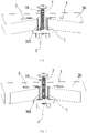
- Embodiment 3 of the present invention discloses the locking assembly 10, including the flexible connecting piece 1, the fixing sheet 2 and the plug 4.
- One end of the flexible connecting piece 1 is connected to the fixing sheet 2, and the other end of the flexible connecting piece 1 passes through the plug 4.
- the flexible connecting piece 1 and the fixing sheet 2 are linked, and thus, the fixing sheet 2 can be driven to get close to the plug 4.
- the plug 4 or both the flexible connecting piece 1 and the plug 4 are provided with the limiting structure 3 to prevent the fixing sheet 2 from moving away from the plug 4.
- the fixing sheet 2 can be driven to get close to the plug 4, so that the fixing sheet 2 abuts against a load-bearing component, for example, abutting against one side of the toilet body 20, and meanwhile, the fixing sheet 2 is prevented by the limiting structure 3 from moving away from the plug 4. Therefore, the locking assembly can quickly fix the fixing sheet 2 for easy installation.
- a load-bearing component for example, abutting against one side of the toilet body 20
- the fixing sheet 2 is prevented by the limiting structure 3 from moving away from the plug 4. Therefore, the locking assembly can quickly fix the fixing sheet 2 for easy installation.
- the fixing sheet 2 When fixing the fixing sheet 2 on one side of the toilet body 20, the fixing sheet 2 passes through the toilet body 20 and then pulls the flexible connecting piece 1, and thus, the flexible connecting piece 1 drives the fixing sheet 2 to move close to the plug 4.
- the fixing sheet 2 When the fixing sheet 2 is located on one side of the toilet body 20, the limiting structure 3 prevents the fixing sheet 2 from moving away from the plug 4. Therefore, the fixing sheet 2 can be quickly fixed to facilitate the installation of the support 30.
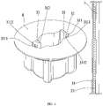
- the limiting bar 31 is arranged on the plug 4, one end of the limiting bar 31 is elastically connected to a side wall of the plug 4, and the limiting bar 31 and another side wall of the plug 4 form the limiting channel 32 for the flexible connecting piece 1 to be inserted.
- the limiting bar 31 is provided with a plurality of first one-way teeth 311, and each of the first one-way teeth 311 includes the first sliding surface 3111 and the first abutting surface 3112.
- the flexible connecting piece 1 is provided with a plurality of second one-way teeth 33, each of the second one-way teeth 33 includes the second sliding surface 331 and a second abutting surface, and the second sliding surface 331 can slide along the first sliding surface 3111.
- the second sliding surface 331 slides along the first sliding surface 3111 and arrives at an end portion of the first sliding surface 3111, the second sliding surface 331 generates a sudden jump, so that the second abutting surface abuts on the first abutting surface 3112.
- the limiting structure 3 is formed by mutual engagement of the plurality of first one-way teeth 311 arranged on the limiting bar 31 and the plurality of second one-way teeth 33 arranged on the flexible connecting piece 1.
- the second sliding surface 331 of one second one-way tooth 33 of the flexible connecting piece 1 is driven to slide along the first sliding surface 3111 of one first one-way tooth 311.
- the flexible connecting piece 1 can be pulled continuously to make the second sliding surface 331 of the next second one-way tooth 33 slide along the first sliding surface 3111 of the next first one-way tooth 311, thereby enabling the fixing sheet 2 to move to and tightly abuts against one side of the toilet body 20 to facilitate the installation of the support 30.
- the first abutting surface 3112 and the second abutting surface are preferably horizontal surfaces. Of course, they can also be inclined surfaces that can achieve the same effect, which are not limited herein.
- the other end of the limiting bar 31 protrudes out of the plug 4 to form the pressing part 312, and pressing the pressing part 312 can change the width of the limiting channel 32. That is, after the pressing part 312 is pressed, the limiting channel 32 can be driven to become wider, so that the second abutting surface is separated from the first abutting surface 3112 to complete the disassembly.
- two or more flexible connecting pieces 1 are provided. With such arrangement, after one of the flexible connecting pieces 1 is separated from the limiting channel 32, the fixing sheet 2 may be in an inclined state, and then the fixing sheet 2 can be extracted out by pulling another flexible connecting piece 1, thus realizing repeated use and reducing cost.
- the fixing sheet 2 and the flexible connecting piece 1 can be connected in many manners.
- the fixing sheet 2 can be provided with the through hole 21; one end of the flexible connecting piece 1 can be provided with the limiting block 11, and the other end of the flexible connecting piece 1 passes through the through hole 21 on the fixing sheet 2, making the limiting block 11 abut on the fixing sheet 2.
- the fixing sheet 2 and the flexible connecting piece 1 are separate elements which facilitate separate fabrication and can be detachably connected using the limiting block 11.
- one end of the flexible connecting piece 1 can be provided with a hinge rod, a side of the fixing sheet 2 can be provided with a hinge hole, and the hinge rod is placed in the hinge hole to realize a connection between the flexible connecting piece 1 and the fixing sheet 2.
- the fixing sheet 2 and the flexible connecting piece 1 in the present embodiment can also be integrally connected.
- the flexible connecting piece 1 is integrally formed with a bottom plate of the fixing sheet 2, as such, only one mold is needed for fabrication.
- Embodiment 4 of the present invention discloses the locking assembly 10.
- the limiting structure 3 is a limiting ball
- the limiting ball is arranged on the end of the flexible connecting piece 1 away from the fixing sheet 2.
- the plug 4 can be provided with a limiting hole.
- Embodiment 5 of the present invention discloses the locking assembly 10.
- the limiting structure 3 is the foldable metallic flexible connecting piece 1.
- One end of the flexible connecting piece 1 is connected to the fixing sheet 2, and the other end of the flexible connecting piece 1 passes through the plug 4.
- the fixing sheet 2 is fixed on one side of the toilet body 20, the fixing sheet 2 obliquely passes through the mounting hole 201 of the toilet body 20 and then back to horizontal.
- the flexible connecting piece is folded by, for example, 90 degrees, which enables the flexible connecting piece 1 with folded rear end to abut against the toilet body 20 to prevent the fixing sheet 2 from moving, thus restricting the fixing sheet 2.
- the plug 4 can be provided with a limiting slot, and the flexible connecting piece 1 with folded rear end is placed in the limiting slot of the plug 4 to prevent shaking and improve stability.
- the limiting structure 3 may be an elastic sheet.
- One end of the elastic sheet is elastically connected to a side wall of the plug 4, and the other end of the elastic sheet and another side wall of the plug 4 form an opening for the flexible connecting piece 1 to be inserted.
- the width of the opening is less than the width of the flexible connecting piece 1. That is, by setting the opening having a width smaller than that of the flexible connecting piece 1, after the flexible connecting piece 1 is inserted, the elastic sheet provides an elastic force to drive the flexible connecting piece 1 to tightly abut against the side wall of the plug 4.
- the opening is driven to be enlarged due to the elastic connection between the end of the elastic sheet and the side wall of the plug 4, thus facilitating the insertion.
- the elastic sheet provides an elastic force to drive the flexible connecting piece 1 to abut against the side wall of the plug 4, thereby achieving a limiting effect.
- the locking assembly 10 may further include the fastener 5.
- the fastener 5 passes through the plug 4 and is connected to the fixing sheet 2, and the fastener 5 may pass through the support 30 to facilitate the fixation of the support 30.
- the fastener 5 is preferably a fastening screw, correspondingly, the threaded hole 22 may be provided on the fixing sheet 2, and the fastening screw and the threaded hole 22 are in a threaded connection.
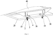
- Embodiment 7 of the present invention discloses a toilet, including the toilet body 20, the above-mentioned locking assembly 10, the support 30, and the cover plate 40.
- the toilet body 20 is provided with the mounting hole 201.
- the fixing sheet 2 obliquely passes through the mounting hole 201, the plug 4 is placed on the mounting hole 201, and the flexible connecting piece 1 and the fixing sheet 2 are linked to drive the fixing sheet 2 to get close to the plug 4, so that the fixing sheet 2 abuts against one side of the toilet body 20.
- the limiting structure 3 prevents the fixing sheet 2 from detaching from the toilet body 20.
- the fastener 5 is connected to the fixing sheet 2 after successively passing through the support 30 and the plug 4, and fixes the support 30 on the other side of the toilet body 20.
- the cover plate 40 is connected to the support 30.
- the support 30 is installed on the toilet body by the locking assembly 10, and the cover plate 40 is installed on the support 30. Specifically, by applying a force to the flexible connecting piece 1, the fixing sheet 2 can be driven to get close to the plug 4, so that the fixing sheet 2 abuts against one side of the toilet body 20, and meanwhile, the fixing sheet 2 is prevented by the limiting structure 3 from moving away from the plug 4. Therefore, the fixing sheet 2 can be quickly fixed for easy installation.
- the fixing sheet 2 passes through the fixing sheet 2 and the plug 4, making the fixing sheet 2 abut against the limiting block 11 of the flexible connecting piece 1.
- the fixing sheet 2 obliquely passes through the mounting hole 201 of the toilet body 20.
- the plug 4 is placed on the mounting hole 201 of the toilet body 20, followed by pulling the flexible connecting piece 1 to drive the fixing sheet 2 to tightly abut on the toilet body 20, and then cutting the flexible connecting piece 1 protruding beyond the toilet body 20.
- the support 30 is placed on the toilet body 20 and locked with a fastening screw. In this way, the support 30 is quickly fixed to the toilet body 20.
- the cover plate 40 can be installed on the toilet body 20 through the support 30.
- the flexible connecting piece 1 is a flexible object, that is, the flexible connecting piece 1 can be bent to allow the fixing sheet 2 to be in an inclined state, which is beneficial for the fixing sheet to pass through the mounting hole 201 of the toilet body 20. After the fixing sheet passes through the mounting hole 201, the fixing sheet 2 can be in a horizontal state, so that two ends of the fixing sheet 2 abut against the toilet body 20. While the limiting structure 3 assists the flexible connecting piece 1 to maintain in a tight state without sliding down.
- first and second are only for the purpose of description, and cannot be understood as indicating or implying relative importance or implicitly indicating the number of indicated technical features. Thus, features defined with “first” and “second” may explicitly or implicitly include one or more of these features. In the description of the present invention, “plurality” means two or more, unless otherwise specifically defined.
- the terms “installation”, “connected”, “connection”, “fixing” and the like should be understood as a broad interpretation.
- it can be a fixed connection, a detachable connection, or integrally formed; it can be a mechanical connection or an electrical connection; it can a direct connection or an indirect connection through an intermediate medium, and it can be an internal communication of two elements or an interaction relationship between two elements.
- the specific meaning of the above-mentioned terms in the present invention can be understood according to specific circumstances.
- a first feature “above” or “below” a second feature may include a direct contact between the first and second features, or an indirect contact therebetween via another feature instead of the direct contact.
- the first feature “above”, “on an upper of” and “on a top of” the second feature may include the first feature being directly above and obliquely above the second feature, or simply mean that the horizontal height of the first feature is larger than that of the second feature.
- the first feature “below”, “on a lower of” and “on a bottom of” the second feature may include the first feature being directly below and obliquely below the second feature, or simply mean that the horizontal height of the first feature is smaller than that of the second feature.
- the terms “one embodiment”, “some embodiments”, “examples”, “specific examples”, or “some examples”, etc. mean specific features, structures, materials or characteristics described in conjunction with the embodiments or examples are included in at least one embodiment or example of the present invention.
- the exemplary expression of the above-mentioned terms should not be understood as necessarily referring to the same embodiment or example.
- the specific features, structures, materials or characteristics described can be combined in any one or more embodiments or examples in a suitable manner.
- those skilled in the art can join and combine different embodiments or examples described in the present specification.
Landscapes
- Engineering & Computer Science (AREA)
- General Engineering & Computer Science (AREA)
- Health & Medical Sciences (AREA)
- Public Health (AREA)
- Mechanical Engineering (AREA)
- Toilet Supplies (AREA)
- Non-Flushing Toilets (AREA)
Applications Claiming Priority (1)
| Application Number | Priority Date | Filing Date | Title |
|---|---|---|---|
| CN202011424998 | 2020-12-08 |
Publications (1)
| Publication Number | Publication Date |
|---|---|
| EP4012203A1 true EP4012203A1 (de) | 2022-06-15 |
Family
ID=78483205
Family Applications (1)
| Application Number | Title | Priority Date | Filing Date |
|---|---|---|---|
| EP21205762.4A Withdrawn EP4012203A1 (de) | 2020-12-08 | 2021-11-01 | Verriegelungsanordnung und toilette |
Country Status (2)
| Country | Link |
|---|---|
| US (1) | US20220175202A1 (de) |
| EP (1) | EP4012203A1 (de) |
Citations (3)
| Publication number | Priority date | Publication date | Assignee | Title |
|---|---|---|---|---|
| US5236293A (en) * | 1991-05-08 | 1993-08-17 | Titan Technology, Inc. | Anchor assembly for fastener |
| US6161999A (en) * | 1999-01-29 | 2000-12-19 | Mechanical Plastics Corp. | Toggle bolt device |
| EP3381342A1 (de) * | 2017-03-31 | 2018-10-03 | Ceravalls Pujol, Sr. Ramón | Vorrichtung zur befestigung eines gegenstandes an einem sanitären möbelstück und sanitäres möbelstück und vorrichtungsanordnung |
Family Cites Families (1)
| Publication number | Priority date | Publication date | Assignee | Title |
|---|---|---|---|---|
| CN107960942A (zh) * | 2017-11-29 | 2018-04-27 | 厦门倍杰特科技股份公司 | 一种马桶盖快速拆装结构 |
-
2021
- 2021-11-01 EP EP21205762.4A patent/EP4012203A1/de not_active Withdrawn
- 2021-12-07 US US17/543,751 patent/US20220175202A1/en not_active Abandoned
Patent Citations (3)
| Publication number | Priority date | Publication date | Assignee | Title |
|---|---|---|---|---|
| US5236293A (en) * | 1991-05-08 | 1993-08-17 | Titan Technology, Inc. | Anchor assembly for fastener |
| US6161999A (en) * | 1999-01-29 | 2000-12-19 | Mechanical Plastics Corp. | Toggle bolt device |
| EP3381342A1 (de) * | 2017-03-31 | 2018-10-03 | Ceravalls Pujol, Sr. Ramón | Vorrichtung zur befestigung eines gegenstandes an einem sanitären möbelstück und sanitäres möbelstück und vorrichtungsanordnung |
Also Published As
| Publication number | Publication date |
|---|---|
| US20220175202A1 (en) | 2022-06-09 |
Similar Documents
| Publication | Publication Date | Title |
|---|---|---|
| US9903643B2 (en) | Drawer assembly | |
| EP2292871A1 (de) | Modulfußboden | |
| US20110091141A1 (en) | Ultrathin Slide Rail Capable of Rapid Installation and Removal | |
| US9194602B2 (en) | Ventilation fan mounting structure | |
| JP6393723B2 (ja) | 連結装置 | |
| JPH08299077A (ja) | 引き出し滑り具用衝撃吸収切り離しラッチ | |
| TWI679950B (zh) | 用於抽屜的前面板、具有該前面板的抽屜以及用於組裝該前面板的方法 | |
| CN107076190A (zh) | 用于家具面板的固定装置 | |
| US20090195975A1 (en) | Fixture | |
| US20130180197A1 (en) | Panel Fastener | |
| CN207355784U (zh) | 包括抽屉侧壁和保持件的组件系统及相应的抽屉 | |
| EP4012203A1 (de) | Verriegelungsanordnung und toilette | |
| CN101167614B (zh) | 一体式抽屉滑轨组件 | |
| KR200479832Y1 (ko) | 가구의 슬라이딩 도어용 슬라이더 | |
| CN115680174B (zh) | 幕墙的龙骨连接结构 | |
| CN113152833B (zh) | 一种调平龙骨及调平装置 | |
| CN113143088B (zh) | 一种锁附组件及马桶 | |
| DE102010043545A1 (de) | Beleuchtungseinrichtung für ein Großelektrogerät | |
| EP2676087B1 (de) | Türgriff für eine haushaltsgerätetür | |
| CN219629178U (zh) | 一种可拆床 | |
| EP4083449B1 (de) | Möbelbaugruppe mit durch lösbare kupplungsvorrichtung befestigbare sitzmodulen | |
| CN219982378U (zh) | 桌子 | |
| GB2432626A (en) | Mount latch structure for a telescoping slide | |
| TWI827445B (zh) | 防止變形之門框夾持結構 | |
| US20050201824A1 (en) | Snap-fit connection structure |
Legal Events
| Date | Code | Title | Description |
|---|---|---|---|
| PUAI | Public reference made under article 153(3) epc to a published international application that has entered the european phase |
Free format text: ORIGINAL CODE: 0009012 |
|
| STAA | Information on the status of an ep patent application or granted ep patent |
Free format text: STATUS: REQUEST FOR EXAMINATION WAS MADE |
|
| 17P | Request for examination filed |
Effective date: 20211122 |
|
| AK | Designated contracting states |
Kind code of ref document: A1 Designated state(s): AL AT BE BG CH CY CZ DE DK EE ES FI FR GB GR HR HU IE IS IT LI LT LU LV MC MK MT NL NO PL PT RO RS SE SI SK SM TR |
|
| STAA | Information on the status of an ep patent application or granted ep patent |
Free format text: STATUS: THE APPLICATION IS DEEMED TO BE WITHDRAWN |
|
| 18D | Application deemed to be withdrawn |
Effective date: 20221216 |