EP4015931B1 - Unité de traversée murale pour le branchement d'un appareil domotique - Google Patents
Unité de traversée murale pour le branchement d'un appareil domotique Download PDFInfo
- Publication number
- EP4015931B1 EP4015931B1 EP21197384.7A EP21197384A EP4015931B1 EP 4015931 B1 EP4015931 B1 EP 4015931B1 EP 21197384 A EP21197384 A EP 21197384A EP 4015931 B1 EP4015931 B1 EP 4015931B1
- Authority
- EP
- European Patent Office
- Prior art keywords
- wall
- grille
- flow channel
- wall outlet
- frame
- Prior art date
- Legal status (The legal status is an assumption and is not a legal conclusion. Google has not performed a legal analysis and makes no representation as to the accuracy of the status listed.)
- Active
Links
Images


Classifications
-
- F—MECHANICAL ENGINEERING; LIGHTING; HEATING; WEAPONS; BLASTING
- F24—HEATING; RANGES; VENTILATING
- F24F—AIR-CONDITIONING; AIR-HUMIDIFICATION; VENTILATION; USE OF AIR CURRENTS FOR SCREENING
- F24F13/00—Details common to, or for air-conditioning, air-humidification, ventilation or use of air currents for screening
- F24F13/02—Ducting arrangements
- F24F13/0209—Ducting arrangements characterised by their connecting means, e.g. flanges
-
- F—MECHANICAL ENGINEERING; LIGHTING; HEATING; WEAPONS; BLASTING
- F24—HEATING; RANGES; VENTILATING
- F24F—AIR-CONDITIONING; AIR-HUMIDIFICATION; VENTILATION; USE OF AIR CURRENTS FOR SCREENING
- F24F13/00—Details common to, or for air-conditioning, air-humidification, ventilation or use of air currents for screening
- F24F13/08—Air-flow control members, e.g. louvres, grilles, flaps or guide plates
- F24F13/082—Grilles, registers or guards
-
- F—MECHANICAL ENGINEERING; LIGHTING; HEATING; WEAPONS; BLASTING
- F24—HEATING; RANGES; VENTILATING
- F24F—AIR-CONDITIONING; AIR-HUMIDIFICATION; VENTILATION; USE OF AIR CURRENTS FOR SCREENING
- F24F7/00—Ventilation
- F24F2007/0025—Ventilation using vent ports in a wall
-
- F—MECHANICAL ENGINEERING; LIGHTING; HEATING; WEAPONS; BLASTING
- F24—HEATING; RANGES; VENTILATING
- F24F—AIR-CONDITIONING; AIR-HUMIDIFICATION; VENTILATION; USE OF AIR CURRENTS FOR SCREENING
- F24F2221/00—Details or features not otherwise provided for
- F24F2221/17—Details or features not otherwise provided for mounted in a wall
Definitions
- the invention relates to a wall feedthrough unit for connecting a domestic appliance.
- Building technology devices in particular heat pumps, multifunctional devices according to DIN EN 16573 or central ventilation devices that are installed inside buildings, require a wall duct to the outside through which the required supply air can be supplied and the exhaust air can be removed.
- a wall duct to the outside through which the required supply air can be supplied and the exhaust air can be removed.
- at least one end of an air line is provided on the heat pump or the central ventilation device and the other end is attached to a wall duct.
- a depth-adjustable wall bushing unit is available DE 10 2017 002 396 A1 known.
- An external part is attached from the outside of the building and an internal part from the inside of the building.
- the outdoor part also includes an external wall grille and a small animal protection grille.
- the flow channel is formed within two mutually telescopic pipe sockets, which can be moved relative to one another in order to be able to adapt to the individual wall thickness of a building wall.
- the wall thickness is known within narrow tolerance ranges, so that it is not necessary to adjust the depth of the flow channel.
- the use of the known wall bushing unit then has the disadvantage that that due to the unnecessary length adjustment, a not inconsiderable proportion of the cross section of the wall opening is blocked from the air flow.
- EP 0 651 210 A2 describes a grille for use near an outlet of a heating, ventilation or air conditioning system that includes a frame and a plurality of slats extending between opposing frame members. Each slat has a spindle rotatably mounted in opposing slots formed in opposing portions of the frame. The slots are open at one end to allow insertion of the blade spindle and the spindle is held at the closed ends of the slots.
- the grid further includes means for holding the lamella spindles in the slots.
- the retaining means includes a member attachable to the frame of the grille such that a portion of the retaining member engages the slat spindles when mounted on the frame and prevents the spindles from moving out of the open ends of the slots.
- Building technology devices that suck in or expel air from the outside of a building are, in particular, a heat pump that can be installed inside, multifunctional devices in accordance with DIN EN 16573 or a ventilation device.
- the three-part design of the wall bushing unit makes assembly particularly easy.
- the construction of the wall duct unit can be completed gradually as the construction of the associated part of the building progresses.
- the external wall grille is a finished unit, preferably formed from stainless steel or aluminum sheet.
- An inner frame extends a little into the depth of the flow channel.
- the inner frame is surrounded by a frame all around. Several slanted slats are arranged within the inner frame.
- a wall duct element which is in particular a cuboid body made of EPS plastic foam, is first inserted into a wall recess.
- the wall recess can be formed from the outset by recesses in the walls, or they can be made into the wall later.
- the wall duct element is then inserted into the wall cutout and, for example, glued into it so that it is airtight Connection results.
- the wall duct element is flush with both the inside and outside of the building.
- the holding frame is put on.
- a holding frame outer element is provided, which is preferably flush with the end face of the wall duct element.
- the connection between the holding frame and the wall duct element is made via screws that engage in dowels, which are either screwed into the hardened EPS plastic foam after foaming or which have been foamed directly into the wall duct element.
- the wall duct element and the holding frame can also be delivered as a fully assembled unit for use in finished building parts, since in this application no adjustment work is necessary on the wall duct element.
- the outer holding frame element can then be covered with reinforcing fabric and / or plastered, so that a top wall layer is created in which the outer holding frame element is embedded. This means that water running off the building wall can only reach the outside over the plastered surface, but no longer into the space between the outer holding frame element and the front side of the wall duct element.
- small animal protection grille fastening bottles are preferably provided, into which a small animal protection grille can be hung.
- a small animal protection grille can also be attached to the external wall grille behind the slats.
- the connection with the holding frame has the advantage that the flow channel can already be closed off during gradual assembly according to the respective construction progress, without the outer wall grille having to be put in place at an early stage. This advantage arises less when building parts of prefabricated houses, but above all when Subsequent installation of a wall duct element in a building wall.
- the final step is to put the external wall grille in place.
- the external wall grille simply needs to be inserted into the area already specified by the holding frame.
- An inner frame of the external wall grille is pushed between the fastening tabs of the holding frame.
- a positive connection can be established, through which the outer wall grille is attached to the holding frame and, via this, indirectly to the wall duct element.
- the fastening points are offset inwards from a wall connection level, i.e. within the flow channel.
- a wall connection level i.e. within the flow channel.
- it is provided there to use two screws per fastening tab on the holding frame fastening bottles and to provide elongated holes in the inner frame of the outer wall grille on the rear edge.
- the screws are tightened, ensuring that the external wall grille is firmly and securely attached. Small tolerances in the plaster layer can be easily compensated for by designing the fastening recesses in the form of elongated holes.
- the screw connections are preferably arranged in such a way that they are covered by the slats in the outer wall grille and are therefore generally not visible in a front view.
- the hidden screw connection in the flow channel also has the advantage that there are no miter cuts, rivets, etc. on the frame, which could be visually disturbing and through which water could penetrate.
- a preferred embodiment also provides that at least one collecting surface in the lower region of the flow channel outer section is formed, which ends at a drip edge.
- the drip edge in turn protrudes over a lower flow channel surface.
- the lower flow channel surface is preferably designed to slope obliquely outwards.
- the fastening means for connecting the outer wall grille to the holding frame are arranged above the collecting surface, as are the rear edges of the slats in the outer wall grille.
- the small animal protection grille is also arranged above the collecting area in the flow channel. Water that either penetrates through driving rain or is sucked in during the supply air operation of the building services system can drip off at the points mentioned and thus reaches the collecting area and from there outwards via additional slats or draining boards beyond the wall connection level.
- a preferred embodiment of the wall bushing unit according to the invention provides at least one additional lamella, which is glued or welded to the back of the upper cross bar of the frame, so that the additional lamella extends from a point outside the wall connection plane to the interior of the flow channel.
- the additional slat thus complements the inner frame in the manner of a lid.
- the additional slat is advantageous in order to close the flow channel at the top.
- the additional slat has the dual function of water that may penetrate from above in the wall connection level to the additional slat and is initially drained to the inside.
- the water can drip onto the top slat in the outer wall grille and then flows out again beyond the wall connection level.
- This labyrinth concept consisting of an additional slat and an upper slat simultaneously creates a flow-related closure at the top and also creates water permeability.
- the frame is to be backed with polyethylene foam sealing strips and on the back of the Foam sealing strips to be applied to the wall surface, an additional swelling tape sealing strip should be provided.
- the ease of assembly of the wall duct unit according to the invention in prefabricated house construction results from the fact that the wall duct element and the holding frame can already be installed in the factory during the production of the building part. All elements necessary for sealing and draining behind water are integrated into the external wall grille.
- the only assembly step in relation to the wall bushing unit is to place the external wall grille and secure it with the four pre-positioned screws. No further work is necessary on either the external wall grille or the building itself. At the same time, it is impossible for seals to be missed or carried out incorrectly due to carelessness.
- the flow channel inner section with a round, in particular an ellipsoidal, cross-section continuously merges into the flow channel inner section with the rectangular or polygonal cross-section. This means that large offset areas that would be perpendicular to the direction of flow and create turbulence are avoided at the transition.
- the wall duct unit In order to separate moisture sucked in during supply air operation as far as possible in the wall duct unit, it can be provided to design parts of the flow channel with at least one small offset step or in a staircase-like manner with several small offset steps. This particularly prevents a film of moisture from forming on the walls and being sucked into the system. With a small offset height of in particular up to 5 mm, maximum up to 10 mm, the main flow is not significantly affected.
- the central axis of the flow channel rises from the outside of the building to the inside of the building to the extent that all areas of the inner wall in the flow channel have a slope towards the outside.
- the outer holding frame part can be designed as a frame made of sheet metal without recesses.
- the small animal protection grille is preferably held interchangeably on the holding frame. This allows it to be removed for cleaning purposes. It can also be exchanged for a grid with a different mesh size, e.g. B. on buildings where high humidity and low temperatures can cause icing on the small animal protection grille in winter.
- the small animal protection grille is also preferably formed as a stamped part made of sheet metal. A certain amount of stiffening is achieved through embossed ribs and/or vertical or flanged outer edges. If the stamped part is bulbous, the convex side is aligned towards the inside of the building, i.e. pointing away from the outer wall grille, so that these parts do not touch each other.
- Figure 1 shows a wall bushing unit 100 in a perspective exploded view, seen from the outside of a building. It essentially consists of three assemblies, namely an external wall grille 210, a holding frame 230 and a wall bushing element 110.
- the cuboid wall bushing element 110 is inserted into a wall cutout in a building.
- the wall duct element 110 is made in particular from EPS foam so that the heat conduction from the outside of the building to the inside of the building is interrupted.
- a flow channel 120 is formed, which is divided into an inner flow channel section 121 with a round cross section and an outer flow channel section 122 with a rectangular cross section.
- the cross sections 121, 122 continuously merge into one another; Offset surfaces that are perpendicular to the direction of flow are avoided.
- a shoulder is formed on the underside as a collecting surface 123, which is arranged above a lower flow channel surface 125 that slopes obliquely outwards and which protrudes outwards beyond this.
- the holding frame 230 consists of a holding frame outer element 231, which is perforated in the manner of a cleaning rail. Fastening tabs 232 extend perpendicularly into the flow channel. These partially extend even further into the depths and form small animal protection grille fastening tabs 234. A small animal protection grille 235 is held thereon.
- the outer frame element 232 can be attached to fastening holes 116 on an outer end face 115 of the wall bushing element 110. To reinforce the fastening holes 116, dowels are screwed in there.
- the last step is to place the outer wall grille 210 on the holding frame 230, whereby invisible fastening recesses on the outer wall grille 210 reach under the fastening screws 233, which are positioned in threads or holes on fastening tabs 232 of the holding frame 230.
- Grooves 117 are formed in the side surfaces of the flow channel outer section 122 in order to accommodate protruding portions of the fastening screws 233 on the holding frame 230. This allows the fastening tabs 232 of the holding frame 210 can be positioned close to the side walls of the flow channel outer section.
- Figure 2 shows the addition of the external wall grille 210 with the holding frame 230, as in Fig. 1 in a perspective view from the outside of the building.
- the holding frame outer element 231 rests on the front, outer end face 115 of the wall duct element 110.
- a small animal protection grille 235 is arranged above the collecting surface 123 in the flow channel.
- the collecting surface 123 is slightly inclined outwards and ends at a drip edge 124 above the lower flow channel surface 125.
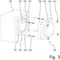
- Figure 3 shows the wall duct element 110 in perspective from behind. i.e. seen from the inside of a building in a perspective exploded view, together with parts of a hose connection adapter 140.
- a connecting piece 112 is formed on a back side 111 of the wall duct element 110. This has a hose receptacle 113, the diameter of which is slightly larger than the rear cross section of the flow channel inner section 121, so that there is a stop edge for a hose adapter 140, which carries an air hose.
- the connecting piece 112 has a fastening hole 114 in each corner for receiving a dowel 145. Alternatively, the dowels 145 can be foamed into the wall duct element 110.
- the hose connection adapter 140 like the wall feed-through element 110, is made of EPS foam and includes a round hose connector 141, which on the one hand engages in the hose receptacle 113 on the connecting piece 112 of the wall feed-through element 110 and on which, on the other hand, the end of an air hose can be pulled. It has a rectangular collar 146, which is reinforced by a support plate 142 made of sheet metal or reinforced plastic.
- Hanger bolts 143 are inserted into the dowels 142 in the fastening holes 114 on the wall duct element 110. This allows the hose connection adapter 140 to be prepared by already attaching the air hose to the hose connector 141 before the hose connection adapter 140 is connected to the wall feedthrough element 110.
- the hose connector 141 is inserted into the recess 113.
- the collar 146 and the support plate 142 which contain holes for receiving the hanger bolts 143, are placed and secured via wing nuts or knurled nuts 144 placed on the hanger bolts 143.
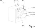
- Figure 4 shows the wall feedthrough element 110 with the hose connection adapter 140 placed on the connecting piece 112 on the back 111 after it has been installed.
- the external wall grille 210 is shown in a frontal view from the outside of the building.
- the outer wall grille 210 has a frame 216, which is intended to rest on the outside of the wall and which stands on a drip rail 229. Towards the front, towards the outside, the frame has a front mirror surface 225.
- the drip strip 229 covers plaster and/or insulation layers below the wall duct element on which the external wall grille 210 is placed.
- the grid structure of the outer wall grid 210 which covers the flow channel in the wall duct element, consists of several slats 211, 213, 214, which slope downwards towards the outside and which overlap each other in the projection onto the wall plane to such an extent that there are no open cross-sectional areas consist. This prevents driving rain from penetrating the flow channel.
- an upper slat 211 and several middle slats 213 appear the same. Only a lower slat 214 differs in that it is located above the Level of the frame 216 extends outwards and also has lateral projections 215.
- FIG. 6 the outer wall grille 210 is shown in a frontal view of its back.
- An inner frame 220 is provided within the frame 216, which is connected to the frame 216 and is aligned perpendicular thereto.
- the inner frame 220 includes parallel lateral inner frame parts 221, between which the slats 211, 213, 214 are held.
- the frame 216 has an inner mirror surface which is intended to rest on the outside of the building wall and is covered with at least one sealing strip 218.
- all four partial mirror surfaces are covered with sealing strips 218 over their entire surface. These are PE foam sealing strips that have miter cuts in the corner areas. Additional swelling tape sealing strips 217 are placed on the edges of the sealing strips 218.
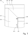
- Figure 7 is an enlarged detailed view of the upper left corner area Figure 6 .
- the side inner frame parts 221 have several punched outs into which z. B. lugs 211.1 of the upper slat 211 are inserted.
- the frame 216 consists of sheet metal whose outer edge is bent perpendicular to the mirror surface. As a result, a mirror surface limited on both sides for receiving the sealing strips 217, 218 is formed between the outer edge of the frame 216 and the inner frame 220.
- the swelling tape sealing strip 217 on the top runs across the entire width of the outer wall grille 210. If water running off on the building facade in the corner area of the outer wall grille 210 is not already retained on the swelling tape sealing strip 217, it will be in the miter plane between the sealing strips 218 directed below. It is important that the miter plane is on the upper edge of the side Inner frame parts 221 ends or is even further inward, i.e. above the slats. This ensures that water is guided downwards along the side inner frame parts 221 and drips off there within the flow channel, where the step is formed by the collecting surface 123. However, water cannot run behind the sealing strips 217, 218 and along the side sections of the frame 216.
- Figure 8 shows a section through the middle of the outer wall grille 210.
- the elongated holes that are open to the rear are clearly visible here and are used to easily attach the outer wall grille 210 to the fastening screws 233 of the holding frame 230 (see Figure 2 ) serve.
- the frame 216 is backed with sealing strips 218. Additionally applied to this are the swelling tape sealing strips 217, which are relatively thin in relation to the sealing strips 218. The rear surfaces of the sealing strips 217, 218 form a mirror surface 219 on the back of the frame 216, which is used to rest the outer wall grille 210 on the outer wall surface of the building. which forms a wall connection level W.
- a recess 224 is made in the lower area of the side inner frame parts 221. The step in the flow channel protrudes into this after the wall duct unit has been completely assembled.
- An additional sealing strip 223 is provided on the outside of the side inner frame parts 221. Its meaning is explained below with reference to Figure 13 explained in more detail.
- Fig. 9 is a detailed view from the top of Figure 8 .
- the path of the water that runs behind a possibly damaged sealing line between the wall connection level W and the swelling tape sealing strip 217 is marked with the dotted line. It is safely guided away from the rear mirror surface 219 on the frame 216, which is equivalent to a wall connection level W, by means of the additional lamella 212. This initially directs the water over the wall connection level W into the interior of the flow channel. There it can then drip onto the upper slat 211. In order to force dripping, the lower edge of the slat 211 is folded over. The lower edges of the other slats are also designed accordingly.
- Figure 10 is a perspective view of the back of a complete external wall grille unit 100.
- the external wall grille 210 is combined here with the holding frame 230 and the small animal protection grille 235.
- the holding frame outer element 231 rests on the mirror surface of the frame 216 of the outer wall grille 210. Since the holding frame outer element 231 is placed on the wall surface and plastered, the wall connection plane W runs between the holding frame outer element 231 and the frame 216.
- the inner frame 220 of the outer wall grille 210 extends into the opening in the outer holding frame element 231.
- the side inner frame parts 221 of the outer wall grille 210 rest on the fastening tabs 232 of the holding frame 230.
- a firm connection is made via the fastening screws 233 as soon as the outer wall grille 210 has been pushed onto the holding frame 230, which was previously installed together with the wall bushing and, if necessary, already plastered.
- Two small animal protection grille fastening tabs 234 are formed on the holding frame fastening tabs 232, which extend beyond the rear edge of the side inner frame parts 221 of the outer wall grille 210 into the interior of the flow channel.
- the small animal protection gate 235 is hung there.
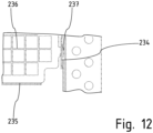
- FIG 12 shows the connection of the small animal protection grille 235 with the holding frame fastening tabs 232 in detail.
- the small animal protection grille 235 includes, in addition to a grid surface 236 in which the webs are kept as thin as possible in order to achieve a large flow-through cross-section, also a wider and partially folded edge area, which gives the small animal protection grille 235 stability. Hooks 237 are punched out on the edge area, which can be inserted into recesses in the small animal guard fastening tabs 234. The small animal protection grille 235 is therefore positively but interchangeably connected to the holding frame.
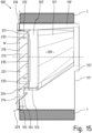
- Figure 13 shows the fully assembled wall bushing unit 100 in a side sectional view, in particular to illustrate the positioning of the parts relative to one another in depth, i.e. in the longitudinal direction of the flow channel.
- the direction of flow for the supply air can be from the outside of the building, which is in Figure 13 to the left, to the right, towards the inside of the building.
- the flow channel 120 in the wall feedthrough element 110 is convergent.
- the flow direction is reversed, so that the flow channel 120 is divergent.
- a wall bushing unit 100 designed according to the invention is suitable for both operating modes in an unchanged manner.
- the collecting surface 123 is formed at the bottom of the flow channel outer section 121, which ends at an overhanging drip edge 124. Because the side frame parts 221 on the outer wall grille 210 each have a recess 224 on both sides, the drip edge 124 can extend over the entire width of the flow channel and thus laterally over the inner frame of the outer wall grille 210. The drip edge 124 is located above the lower slat 214, which is also the in Figure 1 visible inclined surface 125 in the wall bushing element 110 is covered.
- the lower slat 214 protrudes outward over the frame 216 and the wall connection level, so that water that penetrates somewhere in the upper area of the outer wall grille 210 either drips directly onto the lower slat 214 or first onto the step in the flow channel 120 and from there the drip edge 124 reaches the lower slat 214.
- the water according to the invention is not directed directly to the outside, but rather it is always passed over the collecting surface 123 in the flow channel and from there onto the lower lamella 124 and/or the lower flow channel surface 125 of the wall duct element 110 and finally drained away from the wall connection level W via the drip strip 219.
- this diversion ensures that water always reaches an area in the center of the flow cross section and flows downwards from there, but does not flow to the outside of the wall duct element 110, where further building parts 1 adjoin the wall duct element 110.
- FIG 14 A detailed view is shown, which is a section of a perspective sectional view of the wall bushing unit 100.
- the cutting plane is aligned normal to the flow direction and is located in the flow channel outer section 122 of the wall duct element 110.
- the respective lower area of the side inner frame parts 221 of the outer wall grille 210 and the holding frame fastening tabs 232 are visible. These are connected to one another via the fastening screw 233.
- the collecting surface 123 does not represent a plane between the side surfaces of the flow channel outer section 122, but rather rises to a side wall in the respective connection area. Seen from the side, the rising outer area 126 is located outside the area enclosed by the inner frame 220, so that the narrowing of the opening cross section of the flow channel associated with the rising outer area 126 is negligible. However, dripping water is forced by the rising outer area 126 to flow towards the center of the collecting surface 123. This means that it cannot collect in the throat areas on the side walls.
- the swelling tape sealing strip 223 ensures that water that may possibly get between the inner frame part 221 of the outer wall grille 210 and the Holding frame fastening tabs 232 first reach the center of the flow channel, and then from there they have to take the path already described via the collecting surface 123 to the outside.
- the swelling tape sealing strip 223 fills the gap between the side inner frame parts 221 of the outer wall grille 210 and the holding frame fastening tabs 232, there is also a clamping effect during assembly. In this way, the outer wall grille 210 is secured against falling immediately after insertion, even before the fastening screws are tightened.
- Figure 15 shows a second embodiment of a wall bushing unit 100 within a building part 1 in a side sectional view.
- the outer wall grille 210 and the holding frame 230 are unchanged compared to the first embodiment.
- the rectangular flow channel outer section 122' also corresponds to the first embodiment.
- the only difference is a wall duct element 110'.
- a connecting piece 112' is arranged much higher on the back 111' than in the first embodiment, so that the flow channel inner section 121' is also higher on the back 111' and slopes towards the flow channel outer section 122'.
Landscapes
- Engineering & Computer Science (AREA)
- Chemical & Material Sciences (AREA)
- Combustion & Propulsion (AREA)
- Mechanical Engineering (AREA)
- General Engineering & Computer Science (AREA)
- Specific Sealing Or Ventilating Devices For Doors And Windows (AREA)
Claims (21)
- Unité de traversée murale (100 ; 100') destinée à être raccordée à un appareil domotique, comprenant au moins :- un élément de traversée murale (100 ; 100') doté d'un canal d'écoulement (120 ; 120') qui comprend une partie intérieure de canal d'écoulement (121 ; 121') et une partie extérieure de canal d'écoulement (122 ; 122'),- une grille murale extérieure (210) dotée d'un cadre intérieur (220) avec au moins deux parties de cadre intérieur latérales (221) parallèles entre lesquelles sont disposées plusieurs lamelles (211, 213, 214) qui sont orientées respectivement en pente descendante vers une face avant à orienter vers le côté extérieur du bâtiment et dotée d'un encadrement (216) bordant le cadre intérieur (220) et dont la face arrière forme une surface lisse (219) destinée à être appliquée sur un plan de raccordement mural (W) ;
dans laquelle- l'élément de traversée murale (100 ; 100') et la grille murale extérieure (210) sont reliés l'un à l'autre par le biais d'un cadre-support (230),- le cadre-support (230) peut être fixé dans la zone d'une face frontale extérieure (130) de l'élément de traversée murale (100 ; 100') à disposer côté extérieur du bâtiment et présente au moins deux pattes de fixation de cadre-support (232) qui s'étendent jusque dans le canal d'écoulement (120 ; 120'), et- les parties de cadre latérales (221) de la grille murale extérieure (210) chevauchent au moins en partie les pattes de fixation de cadre-support (232), au moins un moyen de fixation étant disposé dans la zone de chevauchement pour relier la grille murale extérieure (210) au cadre-support (230). - Unité de traversée murale (100 ; 100') selon la revendication 1, caractérisée en ce que la partie intérieure de canal d'écoulement (121 ; 121') possède une section transversale ronde et la partie extérieure de canal d'écoulement (122 ; 122') une section transversale rectangulaire ou polygonale, les sections transversales des parties (121 ; 122 ; 121', 122') se fondant progressivement l'une dans l'autre.
- Unité de traversée murale (100 ; 100') selon la revendication 1 ou 2, caractérisée en ce que, dans la zone inférieure de la partie extérieure de canal d'écoulement (122 ; 122'), est formée au moins une surface collectrice (123) qui se termine au-dessus d'une surface inférieure de canal d'écoulement (125) sur un bord d'égouttage (124).
- Unité de traversée murale (100 ; 100') selon la revendication 3, caractérisée en ce que les parties de cadre latérales (221) présentent respectivement un évidement (224) dans lequel pénètre un gradin formé par la surface collectrice (123) et le bord d'égouttage (124) du canal d'écoulement (120 ; 120').
- Unité de traversée murale (100 ; 100') selon la revendication 3 ou 4, caractérisée en ce que des zones extérieures (126) ascendantes sont formées sur la surface collectrice (123) au niveau de la transition avec les parois latérales du canal d'écoulement (120 ; 120').
- Unité de traversée murale (100 ; 100') selon l'une des revendications 3 à 5, caractérisée par une grille de protection contre les petits animaux (235) qui est reliée au cadre-support (230) ou à la grille murale extérieure (210) et disposée au-dessus de la surface collectrice (123).
- Unité de traversée murale (100 ; 100') selon la revendication 6, caractérisée par des pattes de fixation de grille de protection contre les petits animaux (234) auxquelles la grille de protection contre les petits animaux (235) peut être accrochée par ses bords latéraux pourvus de crochets (237), dans des évidements situés dans les pattes de fixation de grille de protection contre les petits animaux (234).
- Unité de traversée murale (100 ; 100') selon l'une des revendications 3 à 7, caractérisée en ce que les zones de chevauchement des parties de cadre latérales (221) de la grille murale extérieure (210) et des pattes de fixation de cadre-support (232), les moyens de fixation et le cas échéant la grille de protection contre les petits animaux (235) sont disposés au-dessus de la surface collectrice (123).
- Unité de traversée murale (100') selon l'une des revendications précédentes, caractérisée en ce qu'une ouverture du canal d'écoulement (120') est disposée sur une face arrière (111 ; 111') de l'élément de traversée murale (110 ; 110') avec un tel décalage vertical par rapport à la partie extérieure de canal d'écoulement (122') que toutes les zones périphériques de la paroi de la partie intérieure de canal d'écoulement (121') descendent en direction de la partie extérieure de canal d'écoulement (122').
- Unité de traversée murale (100 ; 100') selon l'une des revendications précédentes, caractérisée en ce que, sur la grille murale extérieure (210), une lamelle supplémentaire (212), qui est reliée à une entretoise supérieure de l'encadrement (216) et orientée vers une face arrière de la grille murale extérieure (210) de manière inclinée vers le bas, est disposée au-dessus de la lamelle supérieure (211), le bord inférieur de la lamelle supplémentaire (212) maintenant un écart par rapport à la lamelle supérieure (211).
- Unité de traversée murale (100 ; 100') selon l'une des revendications précédentes, caractérisée en ce que la lamelle inférieure (214) présente des saillies latérales (215) qui s'étendent latéralement au-delà du cadre intérieur (220) et qui s'appliquent contre une surface lisse (225) avant de l'encadrement (216) ou sont reliées à celle-ci.
- Unité de traversée murale (100 ; 100') selon l'une des revendications précédentes, caractérisée en ce que la surface lisse arrière (219) de l'encadrement est pourvue de rubans d'étanchéité (218) coupés en biais, les plans en biais se terminant sur les parties de cadre intérieur latérales (221) ou dans l'espace intermédiaire entre celles-ci.
- Unité de traversée murale (100 ; 100') selon l'une des revendications précédentes, caractérisée en ce qu'au moins un ruban d'étanchéité expansif (217) est appliqué sur une surface lisse arrière (219) de l'encadrement, en particulier sur des rubans d'étanchéité (218) disposés sur celle-ci.
- Unité de traversée murale (100 ; 100') selon l'une des revendications précédentes, caractérisée en ce qu'un ruban d'étanchéité (223) est appliqué respectivement sur les côtés extérieurs des parties de cadre intérieur latérales (221) ou sur les côtés intérieurs des pattes de fixation de cadre-support (232), ledit ruban d'étanchéité étant incliné vers le bas en direction de la face arrière de la grille murale extérieure (210).
- Unité de traversée murale (100 ; 100') selon l'une des revendications précédentes, caractérisée par un rejetteau (229) qui est relié à la face inférieure de l'encadrement (216) et qui s'étend vers l'extérieur au-delà de la surface lisse extérieure (225) de l'encadrement (216).
- Unité de traversée murale (100 ; 100') selon l'une des revendications précédentes, caractérisée en ce que les parties de cadre intérieur latérales (221) présentent respectivement au moins un évidement en forme de trou oblong qui s'étend depuis une ouverture sur le bord arrière de la partie de cadre intérieur (221) en direction de la face avant.
- Unité de traversée murale (100 ; 100') selon l'une des revendications précédentes, caractérisée en ce qu'un raccord (112 ; 112') est formé sur la face arrière (111 ; 111') de l'élément de traversée murale (110 ; 110') pour le raccordement d'un adaptateur de raccord de tuyau (140).
- Unité de traversée murale (100 ; 100') selon la revendication 17, caractérisée en ce que plusieurs tiges filetées, auxquelles l'adaptateur de raccord de tuyau (140 ; 140') peut être fixé, sont prévues sur le raccord (112 ; 112') et/ou sur la face arrière (111 ; 111') à côté du raccord (112 ; 112').
- Unité de traversée murale (100 ; 100') selon la revendication 18, caractérisée en ce que les tiges filetées sont maintenues dans des chevilles (145) qui sont encastrées dans l'élément de traversée murale (110 ; 110').
- Unité de traversée murale (100 ; 100') selon la revendication 18 ou 19, caractérisée en ce que l'adaptateur de raccord de tuyau (140), comprenant une plaque de support (142) qui présente des évidements pour le passage des tiges filetées, peut être fixé sur le raccord (112 ; 112') et/ou sur la face arrière (111 ; 111') à côté du raccord (112 ; 112').
- Unité de traversée murale (100 ; 100') selon l'une des revendications 18 à 20, caractérisée en ce que les tiges filetées font respectivement partie d'un goujon (143) qui est inséré dans une cheville (145).
Applications Claiming Priority (1)
| Application Number | Priority Date | Filing Date | Title |
|---|---|---|---|
| DE102020134043.5A DE102020134043A1 (de) | 2020-12-17 | 2020-12-17 | Wanddurchführungseinheit für den Anschluss eines Haustechnikgeräts |
Publications (2)
| Publication Number | Publication Date |
|---|---|
| EP4015931A1 EP4015931A1 (fr) | 2022-06-22 |
| EP4015931B1 true EP4015931B1 (fr) | 2024-03-20 |
Family
ID=77821625
Family Applications (1)
| Application Number | Title | Priority Date | Filing Date |
|---|---|---|---|
| EP21197384.7A Active EP4015931B1 (fr) | 2020-12-17 | 2021-09-17 | Unité de traversée murale pour le branchement d'un appareil domotique |
Country Status (2)
| Country | Link |
|---|---|
| EP (1) | EP4015931B1 (fr) |
| DE (1) | DE102020134043A1 (fr) |
Families Citing this family (1)
| Publication number | Priority date | Publication date | Assignee | Title |
|---|---|---|---|---|
| DE102022122700A1 (de) | 2022-09-07 | 2024-03-07 | Stiebel Eltron Gmbh & Co. Kg | Wanddurchführungseinheit und Außenwandgitter mit einer Abtropfleiste |
Family Cites Families (7)
| Publication number | Priority date | Publication date | Assignee | Title |
|---|---|---|---|---|
| FR2105313A5 (fr) * | 1970-08-13 | 1972-04-28 | Ogny Jean D | |
| US3830146A (en) * | 1970-09-28 | 1974-08-20 | Chore Time Equipment | Ventilator control system |
| US4452024A (en) * | 1979-03-07 | 1984-06-05 | Industrial Louvers, Inc. | Water penetration preventing louver |
| GB2284474A (en) * | 1993-11-02 | 1995-06-07 | Hunter Technical Dev Ltd | Heating ventilating and air conditioning systems |
| US5472380A (en) * | 1994-05-26 | 1995-12-05 | Sarazen, Jr.; Paul M. | Modular forced-air floor register with filter |
| DE102015105651B4 (de) * | 2015-04-14 | 2020-03-12 | Witzenmann Gmbh | Dichtungselement für einen Lüftungskanal, Lüftungssystem mit Dichtung und Verfahren zur Herstellung eines Lüftungssystems |
| DE102017002396A1 (de) | 2017-03-14 | 2018-09-20 | Stiebel Eltron Gmbh & Co. Kg | Wanddurchführung zum Anschluss an ein Haustechnikgerät und Verfahren zur Montage einer Wanddurchführung |
-
2020
- 2020-12-17 DE DE102020134043.5A patent/DE102020134043A1/de active Pending
-
2021
- 2021-09-17 EP EP21197384.7A patent/EP4015931B1/fr active Active
Also Published As
| Publication number | Publication date |
|---|---|
| EP4015931A1 (fr) | 2022-06-22 |
| DE102020134043A1 (de) | 2022-06-23 |
Similar Documents
| Publication | Publication Date | Title |
|---|---|---|
| DE3200210A1 (de) | Lueftungseinrichtung | |
| AT513685A2 (de) | Rahmensystem für ein Insekten- und/oder Pollenschutzgitter | |
| EP0196672A2 (fr) | Panneaux pour recouvrir les murs extérieurs de bâtiments | |
| DE102008020941B4 (de) | Luftführungselement zum Zuführen und/oder Abführen von Luft | |
| CH628951A5 (de) | Lueftungsvorrichtung. | |
| EP4015931B1 (fr) | Unité de traversée murale pour le branchement d'un appareil domotique | |
| EP3783187B1 (fr) | Système avec une fenêtre, une protection solaire et un élément de drainage | |
| DE4026236C2 (de) | Fenster-Lüftungseinrichtung | |
| EP4015932B1 (fr) | Grille murale extérieure pour une unité de traversée murale pour le branchement d'un appareil domotique | |
| EP2806094B1 (fr) | Vantail pour un agencement de porte | |
| DE202008015581U1 (de) | Bauelement für Fensteröffnungen | |
| CH663079A5 (de) | Lueftungsvorrichtung fuer den einbau in eine fenster-, tuer- oder andere wandoeffnung eines gebaeudes. | |
| EP1748143A2 (fr) | Dispositif pour fermer des ouvertures de bâtiments | |
| DE202016101081U1 (de) | Lüftungsvorrichtung für ein Gebäude | |
| DE29701930U1 (de) | Ventilationsvorrichtung | |
| DE102011112866B3 (de) | Insektenschutzvorrichtung | |
| EP4446555B1 (fr) | Dispositif d'ombrage d'une ouverture de bâtiment, ainsi que panneau latéral, rail de guidage latéral et tourillon de liaison associés | |
| DE102014007764B4 (de) | Wohndachfenster mit einer Verblechung zur Abdeckung von äußeren Bereichen eines Flügelrahmens und eines Blendrahmens | |
| EP0450265B1 (fr) | Revêtement de bord pour rebords de fenêtre minces | |
| CH719768A9 (de) | Wanddurchführungseinheit und Wanddurchführungselement mit einer Adapterplatte | |
| CH720018A2 (de) | Wanddurchführungseinheit und Außenwandgitter mit einer Abtropfleiste | |
| DE102023106751A1 (de) | Baukastensystem zur Bildung eines Insektenschutzgitters | |
| DE10132766A1 (de) | Einrichtung zur nachträglichen Wärmeisolierung von Hohlräumen | |
| DE7801023U1 (de) | Lueftungsvorrichtung | |
| DE202006014727U1 (de) | Sockelabschlussprofil |
Legal Events
| Date | Code | Title | Description |
|---|---|---|---|
| PUAI | Public reference made under article 153(3) epc to a published international application that has entered the european phase |
Free format text: ORIGINAL CODE: 0009012 |
|
| STAA | Information on the status of an ep patent application or granted ep patent |
Free format text: STATUS: THE APPLICATION HAS BEEN PUBLISHED |
|
| AK | Designated contracting states |
Kind code of ref document: A1 Designated state(s): AL AT BE BG CH CY CZ DE DK EE ES FI FR GB GR HR HU IE IS IT LI LT LU LV MC MK MT NL NO PL PT RO RS SE SI SK SM TR |
|
| STAA | Information on the status of an ep patent application or granted ep patent |
Free format text: STATUS: REQUEST FOR EXAMINATION WAS MADE |
|
| 17P | Request for examination filed |
Effective date: 20221222 |
|
| RBV | Designated contracting states (corrected) |
Designated state(s): AL AT BE BG CH CY CZ DE DK EE ES FI FR GB GR HR HU IE IS IT LI LT LU LV MC MK MT NL NO PL PT RO RS SE SI SK SM TR |
|
| P01 | Opt-out of the competence of the unified patent court (upc) registered |
Effective date: 20230525 |
|
| GRAP | Despatch of communication of intention to grant a patent |
Free format text: ORIGINAL CODE: EPIDOSNIGR1 |
|
| RIC1 | Information provided on ipc code assigned before grant |
Ipc: F24F 7/00 20210101ALN20230913BHEP Ipc: E06B 7/08 20060101ALI20230913BHEP Ipc: F24F 13/08 20060101ALI20230913BHEP Ipc: F24F 13/02 20060101AFI20230913BHEP |
|
| STAA | Information on the status of an ep patent application or granted ep patent |
Free format text: STATUS: GRANT OF PATENT IS INTENDED |
|
| INTG | Intention to grant announced |
Effective date: 20231019 |
|
| GRAS | Grant fee paid |
Free format text: ORIGINAL CODE: EPIDOSNIGR3 |
|
| GRAA | (expected) grant |
Free format text: ORIGINAL CODE: 0009210 |
|
| STAA | Information on the status of an ep patent application or granted ep patent |
Free format text: STATUS: THE PATENT HAS BEEN GRANTED |
|
| AK | Designated contracting states |
Kind code of ref document: B1 Designated state(s): AL AT BE BG CH CY CZ DE DK EE ES FI FR GB GR HR HU IE IS IT LI LT LU LV MC MK MT NL NO PL PT RO RS SE SI SK SM TR |
|
| REG | Reference to a national code |
Ref country code: GB Ref legal event code: FG4D Free format text: NOT ENGLISH |
|
| REG | Reference to a national code |
Ref country code: CH Ref legal event code: EP |
|
| REG | Reference to a national code |
Ref country code: DE Ref legal event code: R096 Ref document number: 502021003020 Country of ref document: DE |
|
| REG | Reference to a national code |
Ref country code: IE Ref legal event code: FG4D Free format text: LANGUAGE OF EP DOCUMENT: GERMAN |
|
| PG25 | Lapsed in a contracting state [announced via postgrant information from national office to epo] |
Ref country code: LT Free format text: LAPSE BECAUSE OF FAILURE TO SUBMIT A TRANSLATION OF THE DESCRIPTION OR TO PAY THE FEE WITHIN THE PRESCRIBED TIME-LIMIT Effective date: 20240320 |
|
| REG | Reference to a national code |
Ref country code: LT Ref legal event code: MG9D |
|
| PG25 | Lapsed in a contracting state [announced via postgrant information from national office to epo] |
Ref country code: GR Free format text: LAPSE BECAUSE OF FAILURE TO SUBMIT A TRANSLATION OF THE DESCRIPTION OR TO PAY THE FEE WITHIN THE PRESCRIBED TIME-LIMIT Effective date: 20240621 |
|
| PG25 | Lapsed in a contracting state [announced via postgrant information from national office to epo] |
Ref country code: RS Free format text: LAPSE BECAUSE OF FAILURE TO SUBMIT A TRANSLATION OF THE DESCRIPTION OR TO PAY THE FEE WITHIN THE PRESCRIBED TIME-LIMIT Effective date: 20240620 Ref country code: HR Free format text: LAPSE BECAUSE OF FAILURE TO SUBMIT A TRANSLATION OF THE DESCRIPTION OR TO PAY THE FEE WITHIN THE PRESCRIBED TIME-LIMIT Effective date: 20240320 |
|
| REG | Reference to a national code |
Ref country code: NL Ref legal event code: MP Effective date: 20240320 |
|
| PG25 | Lapsed in a contracting state [announced via postgrant information from national office to epo] |
Ref country code: RS Free format text: LAPSE BECAUSE OF FAILURE TO SUBMIT A TRANSLATION OF THE DESCRIPTION OR TO PAY THE FEE WITHIN THE PRESCRIBED TIME-LIMIT Effective date: 20240620 Ref country code: NO Free format text: LAPSE BECAUSE OF FAILURE TO SUBMIT A TRANSLATION OF THE DESCRIPTION OR TO PAY THE FEE WITHIN THE PRESCRIBED TIME-LIMIT Effective date: 20240620 Ref country code: LT Free format text: LAPSE BECAUSE OF FAILURE TO SUBMIT A TRANSLATION OF THE DESCRIPTION OR TO PAY THE FEE WITHIN THE PRESCRIBED TIME-LIMIT Effective date: 20240320 Ref country code: HR Free format text: LAPSE BECAUSE OF FAILURE TO SUBMIT A TRANSLATION OF THE DESCRIPTION OR TO PAY THE FEE WITHIN THE PRESCRIBED TIME-LIMIT Effective date: 20240320 Ref country code: GR Free format text: LAPSE BECAUSE OF FAILURE TO SUBMIT A TRANSLATION OF THE DESCRIPTION OR TO PAY THE FEE WITHIN THE PRESCRIBED TIME-LIMIT Effective date: 20240621 Ref country code: FI Free format text: LAPSE BECAUSE OF FAILURE TO SUBMIT A TRANSLATION OF THE DESCRIPTION OR TO PAY THE FEE WITHIN THE PRESCRIBED TIME-LIMIT Effective date: 20240320 Ref country code: BG Free format text: LAPSE BECAUSE OF FAILURE TO SUBMIT A TRANSLATION OF THE DESCRIPTION OR TO PAY THE FEE WITHIN THE PRESCRIBED TIME-LIMIT Effective date: 20240320 |
|
| PG25 | Lapsed in a contracting state [announced via postgrant information from national office to epo] |
Ref country code: SE Free format text: LAPSE BECAUSE OF FAILURE TO SUBMIT A TRANSLATION OF THE DESCRIPTION OR TO PAY THE FEE WITHIN THE PRESCRIBED TIME-LIMIT Effective date: 20240320 Ref country code: LV Free format text: LAPSE BECAUSE OF FAILURE TO SUBMIT A TRANSLATION OF THE DESCRIPTION OR TO PAY THE FEE WITHIN THE PRESCRIBED TIME-LIMIT Effective date: 20240320 |
|
| PG25 | Lapsed in a contracting state [announced via postgrant information from national office to epo] |
Ref country code: NL Free format text: LAPSE BECAUSE OF FAILURE TO SUBMIT A TRANSLATION OF THE DESCRIPTION OR TO PAY THE FEE WITHIN THE PRESCRIBED TIME-LIMIT Effective date: 20240320 |
|
| PG25 | Lapsed in a contracting state [announced via postgrant information from national office to epo] |
Ref country code: NL Free format text: LAPSE BECAUSE OF FAILURE TO SUBMIT A TRANSLATION OF THE DESCRIPTION OR TO PAY THE FEE WITHIN THE PRESCRIBED TIME-LIMIT Effective date: 20240320 |
|
| PG25 | Lapsed in a contracting state [announced via postgrant information from national office to epo] |
Ref country code: IS Free format text: LAPSE BECAUSE OF FAILURE TO SUBMIT A TRANSLATION OF THE DESCRIPTION OR TO PAY THE FEE WITHIN THE PRESCRIBED TIME-LIMIT Effective date: 20240720 |
|
| PG25 | Lapsed in a contracting state [announced via postgrant information from national office to epo] |
Ref country code: PT Free format text: LAPSE BECAUSE OF FAILURE TO SUBMIT A TRANSLATION OF THE DESCRIPTION OR TO PAY THE FEE WITHIN THE PRESCRIBED TIME-LIMIT Effective date: 20240722 Ref country code: SM Free format text: LAPSE BECAUSE OF FAILURE TO SUBMIT A TRANSLATION OF THE DESCRIPTION OR TO PAY THE FEE WITHIN THE PRESCRIBED TIME-LIMIT Effective date: 20240320 |
|
| PG25 | Lapsed in a contracting state [announced via postgrant information from national office to epo] |
Ref country code: ES Free format text: LAPSE BECAUSE OF FAILURE TO SUBMIT A TRANSLATION OF THE DESCRIPTION OR TO PAY THE FEE WITHIN THE PRESCRIBED TIME-LIMIT Effective date: 20240320 |
|
| PG25 | Lapsed in a contracting state [announced via postgrant information from national office to epo] |
Ref country code: EE Free format text: LAPSE BECAUSE OF FAILURE TO SUBMIT A TRANSLATION OF THE DESCRIPTION OR TO PAY THE FEE WITHIN THE PRESCRIBED TIME-LIMIT Effective date: 20240320 Ref country code: CZ Free format text: LAPSE BECAUSE OF FAILURE TO SUBMIT A TRANSLATION OF THE DESCRIPTION OR TO PAY THE FEE WITHIN THE PRESCRIBED TIME-LIMIT Effective date: 20240320 |
|
| PG25 | Lapsed in a contracting state [announced via postgrant information from national office to epo] |
Ref country code: PL Free format text: LAPSE BECAUSE OF FAILURE TO SUBMIT A TRANSLATION OF THE DESCRIPTION OR TO PAY THE FEE WITHIN THE PRESCRIBED TIME-LIMIT Effective date: 20240320 |
|
| PG25 | Lapsed in a contracting state [announced via postgrant information from national office to epo] |
Ref country code: SK Free format text: LAPSE BECAUSE OF FAILURE TO SUBMIT A TRANSLATION OF THE DESCRIPTION OR TO PAY THE FEE WITHIN THE PRESCRIBED TIME-LIMIT Effective date: 20240320 |
|
| PG25 | Lapsed in a contracting state [announced via postgrant information from national office to epo] |
Ref country code: SM Free format text: LAPSE BECAUSE OF FAILURE TO SUBMIT A TRANSLATION OF THE DESCRIPTION OR TO PAY THE FEE WITHIN THE PRESCRIBED TIME-LIMIT Effective date: 20240320 Ref country code: SK Free format text: LAPSE BECAUSE OF FAILURE TO SUBMIT A TRANSLATION OF THE DESCRIPTION OR TO PAY THE FEE WITHIN THE PRESCRIBED TIME-LIMIT Effective date: 20240320 Ref country code: RO Free format text: LAPSE BECAUSE OF FAILURE TO SUBMIT A TRANSLATION OF THE DESCRIPTION OR TO PAY THE FEE WITHIN THE PRESCRIBED TIME-LIMIT Effective date: 20240320 Ref country code: PT Free format text: LAPSE BECAUSE OF FAILURE TO SUBMIT A TRANSLATION OF THE DESCRIPTION OR TO PAY THE FEE WITHIN THE PRESCRIBED TIME-LIMIT Effective date: 20240722 Ref country code: PL Free format text: LAPSE BECAUSE OF FAILURE TO SUBMIT A TRANSLATION OF THE DESCRIPTION OR TO PAY THE FEE WITHIN THE PRESCRIBED TIME-LIMIT Effective date: 20240320 Ref country code: IS Free format text: LAPSE BECAUSE OF FAILURE TO SUBMIT A TRANSLATION OF THE DESCRIPTION OR TO PAY THE FEE WITHIN THE PRESCRIBED TIME-LIMIT Effective date: 20240720 Ref country code: ES Free format text: LAPSE BECAUSE OF FAILURE TO SUBMIT A TRANSLATION OF THE DESCRIPTION OR TO PAY THE FEE WITHIN THE PRESCRIBED TIME-LIMIT Effective date: 20240320 Ref country code: EE Free format text: LAPSE BECAUSE OF FAILURE TO SUBMIT A TRANSLATION OF THE DESCRIPTION OR TO PAY THE FEE WITHIN THE PRESCRIBED TIME-LIMIT Effective date: 20240320 Ref country code: CZ Free format text: LAPSE BECAUSE OF FAILURE TO SUBMIT A TRANSLATION OF THE DESCRIPTION OR TO PAY THE FEE WITHIN THE PRESCRIBED TIME-LIMIT Effective date: 20240320 |
|
| PG25 | Lapsed in a contracting state [announced via postgrant information from national office to epo] |
Ref country code: IT Free format text: LAPSE BECAUSE OF FAILURE TO SUBMIT A TRANSLATION OF THE DESCRIPTION OR TO PAY THE FEE WITHIN THE PRESCRIBED TIME-LIMIT Effective date: 20240320 |
|
| REG | Reference to a national code |
Ref country code: DE Ref legal event code: R097 Ref document number: 502021003020 Country of ref document: DE |
|
| PG25 | Lapsed in a contracting state [announced via postgrant information from national office to epo] |
Ref country code: IT Free format text: LAPSE BECAUSE OF FAILURE TO SUBMIT A TRANSLATION OF THE DESCRIPTION OR TO PAY THE FEE WITHIN THE PRESCRIBED TIME-LIMIT Effective date: 20240320 |
|
| PG25 | Lapsed in a contracting state [announced via postgrant information from national office to epo] |
Ref country code: DK Free format text: LAPSE BECAUSE OF FAILURE TO SUBMIT A TRANSLATION OF THE DESCRIPTION OR TO PAY THE FEE WITHIN THE PRESCRIBED TIME-LIMIT Effective date: 20240320 |
|
| PLBE | No opposition filed within time limit |
Free format text: ORIGINAL CODE: 0009261 |
|
| STAA | Information on the status of an ep patent application or granted ep patent |
Free format text: STATUS: NO OPPOSITION FILED WITHIN TIME LIMIT |
|
| PG25 | Lapsed in a contracting state [announced via postgrant information from national office to epo] |
Ref country code: DK Free format text: LAPSE BECAUSE OF FAILURE TO SUBMIT A TRANSLATION OF THE DESCRIPTION OR TO PAY THE FEE WITHIN THE PRESCRIBED TIME-LIMIT Effective date: 20240320 |
|
| 26N | No opposition filed |
Effective date: 20241223 |
|
| PG25 | Lapsed in a contracting state [announced via postgrant information from national office to epo] |
Ref country code: MC Free format text: LAPSE BECAUSE OF FAILURE TO SUBMIT A TRANSLATION OF THE DESCRIPTION OR TO PAY THE FEE WITHIN THE PRESCRIBED TIME-LIMIT Effective date: 20240320 Ref country code: SI Free format text: LAPSE BECAUSE OF FAILURE TO SUBMIT A TRANSLATION OF THE DESCRIPTION OR TO PAY THE FEE WITHIN THE PRESCRIBED TIME-LIMIT Effective date: 20240320 |
|
| REG | Reference to a national code |
Ref country code: CH Ref legal event code: PL |
|
| PG25 | Lapsed in a contracting state [announced via postgrant information from national office to epo] |
Ref country code: LU Free format text: LAPSE BECAUSE OF NON-PAYMENT OF DUE FEES Effective date: 20240917 |
|
| REG | Reference to a national code |
Ref country code: BE Ref legal event code: MM Effective date: 20240930 |
|
| PG25 | Lapsed in a contracting state [announced via postgrant information from national office to epo] |
Ref country code: BE Free format text: LAPSE BECAUSE OF NON-PAYMENT OF DUE FEES Effective date: 20240930 |
|
| PG25 | Lapsed in a contracting state [announced via postgrant information from national office to epo] |
Ref country code: FR Free format text: LAPSE BECAUSE OF NON-PAYMENT OF DUE FEES Effective date: 20240930 |
|
| PG25 | Lapsed in a contracting state [announced via postgrant information from national office to epo] |
Ref country code: CH Free format text: LAPSE BECAUSE OF NON-PAYMENT OF DUE FEES Effective date: 20240930 |
|
| PG25 | Lapsed in a contracting state [announced via postgrant information from national office to epo] |
Ref country code: IE Free format text: LAPSE BECAUSE OF NON-PAYMENT OF DUE FEES Effective date: 20240917 |
|
| PGFP | Annual fee paid to national office [announced via postgrant information from national office to epo] |
Ref country code: DE Payment date: 20250919 Year of fee payment: 5 |
|
| PGFP | Annual fee paid to national office [announced via postgrant information from national office to epo] |
Ref country code: AT Payment date: 20251020 Year of fee payment: 5 |
|
| PG25 | Lapsed in a contracting state [announced via postgrant information from national office to epo] |
Ref country code: CY Free format text: LAPSE BECAUSE OF FAILURE TO SUBMIT A TRANSLATION OF THE DESCRIPTION OR TO PAY THE FEE WITHIN THE PRESCRIBED TIME-LIMIT; INVALID AB INITIO Effective date: 20210917 |
|
| PG25 | Lapsed in a contracting state [announced via postgrant information from national office to epo] |
Ref country code: HU Free format text: LAPSE BECAUSE OF FAILURE TO SUBMIT A TRANSLATION OF THE DESCRIPTION OR TO PAY THE FEE WITHIN THE PRESCRIBED TIME-LIMIT; INVALID AB INITIO Effective date: 20210917 |