EP4021700B1 - Plaque porte-filière pour la granulation à chaud par face de filière de matières fondues, et procédé de fabrication associé - Google Patents
Plaque porte-filière pour la granulation à chaud par face de filière de matières fondues, et procédé de fabrication associé Download PDFInfo
- Publication number
- EP4021700B1 EP4021700B1 EP20785945.5A EP20785945A EP4021700B1 EP 4021700 B1 EP4021700 B1 EP 4021700B1 EP 20785945 A EP20785945 A EP 20785945A EP 4021700 B1 EP4021700 B1 EP 4021700B1
- Authority
- EP
- European Patent Office
- Prior art keywords
- die plate
- perforated plate
- foregoing
- hollow chamber
- layer
- Prior art date
- Legal status (The legal status is an assumption and is not a legal conclusion. Google has not performed a legal analysis and makes no representation as to the accuracy of the status listed.)
- Active
Links
Images




Classifications
-
- B—PERFORMING OPERATIONS; TRANSPORTING
- B22—CASTING; POWDER METALLURGY
- B22F—WORKING METALLIC POWDER; MANUFACTURE OF ARTICLES FROM METALLIC POWDER; MAKING METALLIC POWDER; APPARATUS OR DEVICES SPECIALLY ADAPTED FOR METALLIC POWDER
- B22F5/00—Manufacture of workpieces or articles from metallic powder characterised by the special shape of the product
- B22F5/10—Manufacture of workpieces or articles from metallic powder characterised by the special shape of the product of articles with cavities or holes, not otherwise provided for in the preceding subgroups
-
- B—PERFORMING OPERATIONS; TRANSPORTING
- B29—WORKING OF PLASTICS; WORKING OF SUBSTANCES IN A PLASTIC STATE IN GENERAL
- B29B—PREPARATION OR PRETREATMENT OF THE MATERIAL TO BE SHAPED; MAKING GRANULES OR PREFORMS; RECOVERY OF PLASTICS OR OTHER CONSTITUENTS OF WASTE MATERIAL CONTAINING PLASTICS
- B29B13/00—Conditioning or physical treatment of the material to be shaped
- B29B13/02—Conditioning or physical treatment of the material to be shaped by heating
- B29B13/022—Melting the material to be shaped
-
- B—PERFORMING OPERATIONS; TRANSPORTING
- B29—WORKING OF PLASTICS; WORKING OF SUBSTANCES IN A PLASTIC STATE IN GENERAL
- B29B—PREPARATION OR PRETREATMENT OF THE MATERIAL TO BE SHAPED; MAKING GRANULES OR PREFORMS; RECOVERY OF PLASTICS OR OTHER CONSTITUENTS OF WASTE MATERIAL CONTAINING PLASTICS
- B29B7/00—Mixing; Kneading
- B29B7/30—Mixing; Kneading continuous, with mechanical mixing or kneading devices
- B29B7/58—Component parts, details or accessories; Auxiliary operations
- B29B7/582—Component parts, details or accessories; Auxiliary operations for discharging, e.g. doors
-
- B—PERFORMING OPERATIONS; TRANSPORTING
- B29—WORKING OF PLASTICS; WORKING OF SUBSTANCES IN A PLASTIC STATE IN GENERAL
- B29B—PREPARATION OR PRETREATMENT OF THE MATERIAL TO BE SHAPED; MAKING GRANULES OR PREFORMS; RECOVERY OF PLASTICS OR OTHER CONSTITUENTS OF WASTE MATERIAL CONTAINING PLASTICS
- B29B7/00—Mixing; Kneading
- B29B7/80—Component parts, details or accessories; Auxiliary operations
- B29B7/82—Heating or cooling
- B29B7/826—Apparatus therefor
-
- B—PERFORMING OPERATIONS; TRANSPORTING
- B29—WORKING OF PLASTICS; WORKING OF SUBSTANCES IN A PLASTIC STATE IN GENERAL
- B29B—PREPARATION OR PRETREATMENT OF THE MATERIAL TO BE SHAPED; MAKING GRANULES OR PREFORMS; RECOVERY OF PLASTICS OR OTHER CONSTITUENTS OF WASTE MATERIAL CONTAINING PLASTICS
- B29B9/00—Making granules
- B29B9/02—Making granules by dividing preformed material
- B29B9/06—Making granules by dividing preformed material in the form of filamentary material, e.g. combined with extrusion
- B29B9/065—Making granules by dividing preformed material in the form of filamentary material, e.g. combined with extrusion under-water, e.g. underwater pelletizers
-
- B—PERFORMING OPERATIONS; TRANSPORTING
- B29—WORKING OF PLASTICS; WORKING OF SUBSTANCES IN A PLASTIC STATE IN GENERAL
- B29C—SHAPING OR JOINING OF PLASTICS; SHAPING OF MATERIAL IN A PLASTIC STATE, NOT OTHERWISE PROVIDED FOR; AFTER-TREATMENT OF THE SHAPED PRODUCTS, e.g. REPAIRING
- B29C33/00—Moulds or cores; Details thereof or accessories therefor
- B29C33/38—Moulds or cores; Details thereof or accessories therefor characterised by the material or the manufacturing process
- B29C33/3842—Manufacturing moulds, e.g. shaping the mould surface by machining
-
- B—PERFORMING OPERATIONS; TRANSPORTING
- B29—WORKING OF PLASTICS; WORKING OF SUBSTANCES IN A PLASTIC STATE IN GENERAL
- B29C—SHAPING OR JOINING OF PLASTICS; SHAPING OF MATERIAL IN A PLASTIC STATE, NOT OTHERWISE PROVIDED FOR; AFTER-TREATMENT OF THE SHAPED PRODUCTS, e.g. REPAIRING
- B29C48/00—Extrusion moulding, i.e. expressing the moulding material through a die or nozzle which imparts the desired form; Apparatus therefor
- B29C48/001—Combinations of extrusion moulding with other shaping operations
- B29C48/0022—Combinations of extrusion moulding with other shaping operations combined with cutting
-
- B—PERFORMING OPERATIONS; TRANSPORTING
- B29—WORKING OF PLASTICS; WORKING OF SUBSTANCES IN A PLASTIC STATE IN GENERAL
- B29C—SHAPING OR JOINING OF PLASTICS; SHAPING OF MATERIAL IN A PLASTIC STATE, NOT OTHERWISE PROVIDED FOR; AFTER-TREATMENT OF THE SHAPED PRODUCTS, e.g. REPAIRING
- B29C48/00—Extrusion moulding, i.e. expressing the moulding material through a die or nozzle which imparts the desired form; Apparatus therefor
- B29C48/022—Extrusion moulding, i.e. expressing the moulding material through a die or nozzle which imparts the desired form; Apparatus therefor characterised by the choice of material
-
- B—PERFORMING OPERATIONS; TRANSPORTING
- B29—WORKING OF PLASTICS; WORKING OF SUBSTANCES IN A PLASTIC STATE IN GENERAL
- B29C—SHAPING OR JOINING OF PLASTICS; SHAPING OF MATERIAL IN A PLASTIC STATE, NOT OTHERWISE PROVIDED FOR; AFTER-TREATMENT OF THE SHAPED PRODUCTS, e.g. REPAIRING
- B29C48/00—Extrusion moulding, i.e. expressing the moulding material through a die or nozzle which imparts the desired form; Apparatus therefor
- B29C48/03—Extrusion moulding, i.e. expressing the moulding material through a die or nozzle which imparts the desired form; Apparatus therefor characterised by the shape of the extruded material at extrusion
- B29C48/05—Filamentary, e.g. strands
-
- B—PERFORMING OPERATIONS; TRANSPORTING
- B29—WORKING OF PLASTICS; WORKING OF SUBSTANCES IN A PLASTIC STATE IN GENERAL
- B29C—SHAPING OR JOINING OF PLASTICS; SHAPING OF MATERIAL IN A PLASTIC STATE, NOT OTHERWISE PROVIDED FOR; AFTER-TREATMENT OF THE SHAPED PRODUCTS, e.g. REPAIRING
- B29C48/00—Extrusion moulding, i.e. expressing the moulding material through a die or nozzle which imparts the desired form; Apparatus therefor
- B29C48/25—Component parts, details or accessories; Auxiliary operations
- B29C48/30—Extrusion nozzles or dies
- B29C48/3001—Extrusion nozzles or dies characterised by the material or their manufacturing process
-
- B—PERFORMING OPERATIONS; TRANSPORTING
- B29—WORKING OF PLASTICS; WORKING OF SUBSTANCES IN A PLASTIC STATE IN GENERAL
- B29C—SHAPING OR JOINING OF PLASTICS; SHAPING OF MATERIAL IN A PLASTIC STATE, NOT OTHERWISE PROVIDED FOR; AFTER-TREATMENT OF THE SHAPED PRODUCTS, e.g. REPAIRING
- B29C48/00—Extrusion moulding, i.e. expressing the moulding material through a die or nozzle which imparts the desired form; Apparatus therefor
- B29C48/25—Component parts, details or accessories; Auxiliary operations
- B29C48/30—Extrusion nozzles or dies
- B29C48/345—Extrusion nozzles comprising two or more adjacently arranged ports, for simultaneously extruding multiple strands, e.g. for pelletising
-
- B—PERFORMING OPERATIONS; TRANSPORTING
- B33—ADDITIVE MANUFACTURING TECHNOLOGY
- B33Y—ADDITIVE MANUFACTURING, i.e. MANUFACTURING OF THREE-DIMENSIONAL [3D] OBJECTS BY ADDITIVE DEPOSITION, ADDITIVE AGGLOMERATION OR ADDITIVE LAYERING, e.g. BY 3D PRINTING, STEREOLITHOGRAPHY OR SELECTIVE LASER SINTERING
- B33Y80/00—Products made by additive manufacturing
-
- B—PERFORMING OPERATIONS; TRANSPORTING
- B22—CASTING; POWDER METALLURGY
- B22F—WORKING METALLIC POWDER; MANUFACTURE OF ARTICLES FROM METALLIC POWDER; MAKING METALLIC POWDER; APPARATUS OR DEVICES SPECIALLY ADAPTED FOR METALLIC POWDER
- B22F10/00—Additive manufacturing of workpieces or articles from metallic powder
- B22F10/20—Direct sintering or melting
- B22F10/28—Powder bed fusion, e.g. selective laser melting [SLM] or electron beam melting [EBM]
-
- B—PERFORMING OPERATIONS; TRANSPORTING
- B22—CASTING; POWDER METALLURGY
- B22F—WORKING METALLIC POWDER; MANUFACTURE OF ARTICLES FROM METALLIC POWDER; MAKING METALLIC POWDER; APPARATUS OR DEVICES SPECIALLY ADAPTED FOR METALLIC POWDER
- B22F2998/00—Supplementary information concerning processes or compositions relating to powder metallurgy
- B22F2998/10—Processes characterised by the sequence of their steps
-
- B—PERFORMING OPERATIONS; TRANSPORTING
- B22—CASTING; POWDER METALLURGY
- B22F—WORKING METALLIC POWDER; MANUFACTURE OF ARTICLES FROM METALLIC POWDER; MAKING METALLIC POWDER; APPARATUS OR DEVICES SPECIALLY ADAPTED FOR METALLIC POWDER
- B22F2999/00—Aspects linked to processes or compositions used in powder metallurgy
-
- B—PERFORMING OPERATIONS; TRANSPORTING
- B29—WORKING OF PLASTICS; WORKING OF SUBSTANCES IN A PLASTIC STATE IN GENERAL
- B29C—SHAPING OR JOINING OF PLASTICS; SHAPING OF MATERIAL IN A PLASTIC STATE, NOT OTHERWISE PROVIDED FOR; AFTER-TREATMENT OF THE SHAPED PRODUCTS, e.g. REPAIRING
- B29C48/00—Extrusion moulding, i.e. expressing the moulding material through a die or nozzle which imparts the desired form; Apparatus therefor
- B29C48/03—Extrusion moulding, i.e. expressing the moulding material through a die or nozzle which imparts the desired form; Apparatus therefor characterised by the shape of the extruded material at extrusion
- B29C48/04—Particle-shaped
-
- B—PERFORMING OPERATIONS; TRANSPORTING
- B29—WORKING OF PLASTICS; WORKING OF SUBSTANCES IN A PLASTIC STATE IN GENERAL
- B29C—SHAPING OR JOINING OF PLASTICS; SHAPING OF MATERIAL IN A PLASTIC STATE, NOT OTHERWISE PROVIDED FOR; AFTER-TREATMENT OF THE SHAPED PRODUCTS, e.g. REPAIRING
- B29C64/00—Additive manufacturing, i.e. manufacturing of three-dimensional [3D] objects by additive deposition, additive agglomeration or additive layering, e.g. by 3D printing, stereolithography or selective laser sintering
- B29C64/10—Processes of additive manufacturing
- B29C64/106—Processes of additive manufacturing using only liquids or viscous materials, e.g. depositing a continuous bead of viscous material
- B29C64/118—Processes of additive manufacturing using only liquids or viscous materials, e.g. depositing a continuous bead of viscous material using filamentary material being melted, e.g. fused deposition modelling [FDM]
-
- B—PERFORMING OPERATIONS; TRANSPORTING
- B29—WORKING OF PLASTICS; WORKING OF SUBSTANCES IN A PLASTIC STATE IN GENERAL
- B29L—INDEXING SCHEME ASSOCIATED WITH SUBCLASS B29C, RELATING TO PARTICULAR ARTICLES
- B29L2031/00—Other particular articles
- B29L2031/757—Moulds, cores, dies
-
- B—PERFORMING OPERATIONS; TRANSPORTING
- B33—ADDITIVE MANUFACTURING TECHNOLOGY
- B33Y—ADDITIVE MANUFACTURING, i.e. MANUFACTURING OF THREE-DIMENSIONAL [3D] OBJECTS BY ADDITIVE DEPOSITION, ADDITIVE AGGLOMERATION OR ADDITIVE LAYERING, e.g. BY 3D PRINTING, STEREOLITHOGRAPHY OR SELECTIVE LASER SINTERING
- B33Y10/00—Processes of additive manufacturing
-
- B—PERFORMING OPERATIONS; TRANSPORTING
- B33—ADDITIVE MANUFACTURING TECHNOLOGY
- B33Y—ADDITIVE MANUFACTURING, i.e. MANUFACTURING OF THREE-DIMENSIONAL [3D] OBJECTS BY ADDITIVE DEPOSITION, ADDITIVE AGGLOMERATION OR ADDITIVE LAYERING, e.g. BY 3D PRINTING, STEREOLITHOGRAPHY OR SELECTIVE LASER SINTERING
- B33Y30/00—Apparatus for additive manufacturing; Details thereof or accessories therefor
Definitions
- the present invention relates generally to the granulation of molten materials such as polymer melts, which are pressed through the melt channels of a perforated plate and are hot-cut off on the outlet side and divided into granules.
- the invention relates on the one hand to the perforated plate with a perforated plate body which has melt channels which lead through the perforated plate body and open out in a ring-shaped distribution on an outlet surface, on which emerging melt strands are hot-cut off by a rotating knife, a granulating head with such a perforated plate and a granulator, in particular underwater, water ring or air granulator with such a hot-cut granulating head.
- the invention relates to a method for producing such a perforated plate.
- Such perforated plates can work together with a knife head of the granulator, whose rotating knives scrape along the exit surface of the perforated plate in order to cut off the melt strands emerging from the melt channels while they are still hot, whereby the exit surface is
- An engagement or counter surface for the rotating knives is formed around the mouths of the melt channels, which surface can often be flat, but can also be spherical, concave or curved in order to support a knife edge moving along it in a flat or linear manner, depending on the knife contour.
- the knives rotate in a water bath so that the pellets do not stick together and solidify or cool down to such an extent that they are easier to handle.
- the blades and the front of the perforated plate are not positioned in a water bath, but are surrounded on the circumference by a ring-shaped, passing water stream that entrains and transports the knocked-off pellets away, cooling them in the process to initiate solidification.
- the rotating blades cut the melt strands emerging from the front of the perforated plate dry and throw the still hot, melt-shaped granules into the rotating water ring.
- the "water ring” does not necessarily have to consist of water, which can nevertheless be the case, but can also comprise another transport and/or cooling medium, for example in the form of a liquid mixture of substances or at least partially in the form of a droplet and/or spray mist stream or a mixture of these.
- another transport and/or cooling medium for example in the form of a liquid mixture of substances or at least partially in the form of a droplet and/or spray mist stream or a mixture of these.
- the water bath or the water flow passing the perforated plate and the knives does not necessarily have to consist of water, which can nevertheless be the case, but another transport and/or cooling medium can also be used in an analogous manner.
- the hot cutting takes place dry, whereby a rotating knife can also move along a perforated plate to cut off the melt strands emerging from the channel openings.
- the hot-cut granulate is transported further by an air stream and cooled, which takes longer due to the lower thermal conductivity of air compared to water.
- the perforated plates are not only subject to mechanical stress from the passing knives, but also to complex thermal requirements resulting from the hot cutting.
- the melt or melt strands should flow through and exit the perforated plate within a certain temperature window in order to prevent the melt channels from freezing and at the same time to comply with temperature limits of the material to be pelletized. This means that the perforated plate should have a certain, often relatively high temperature.
- the environment of the perforated plate in the form of the water bath or water ring is quite cold, so that very high temperature gradients occur on the perforated plates.
- perforated plates are sometimes designed to be thermally insulated or provided with insulation.
- insulation can, for example, comprise a hollow chamber inside the perforated plate body, which can be designed to be as large as possible in order to avoid direct heat transfer from the hot inlet side to the cold outlet side of the perforated plate via the thermally highly conductive, usually metallic material of the perforated plate body.
- water ring granulators Even if cooling by the passing water ring and freezing of the melt channels or channel openings is less problematic in water ring granulators, water ring granulators must also an exact temperature control must be maintained for the material to be granulated. This also applies in a similar way to air granulators. Water ring granulators and air granulators are not only used for granulating thermoplastics, but also for granulating pharmaceutical substances or foodstuffs, which usually react sensitively to incorrect temperatures during granulation and require a very narrow temperature window, so that the perforated plate can be sensitively heated and/or cooled or insulated.
- Perforated plates for underwater granulation are known, for example, from the publications DE 10 2014 116 361 A1 , DE 35 32 937 A1 , US 2006/0165834 A1 , US 2007/0254059 A1 , WO 2010/019667 A1 or DE 40 36 196 A1 known.
- WO 2010/019667 A1 proposes isolating the melt channels and the wear ring on which the melt channels open from the rest of the perforated plate body by inserts made of poorly conductive material.
- DE 40 36 196 A1 proposes to provide heating medium channels between the melt channels in the perforated plate and to form additional insulating channels in the perforated plate body between these heating medium channels and the front side of the plate cooled by the water bath, which forms the perforated plate outlet surface onto which the melt channels open, through which an inert gas flows as an insulating medium.
- Perforated plates for water ring granulation are known, for example, from the publications AT 508 199 B1 or DE 10 2012 012 070 A1 known.
- Perforated plates for air or cool air granulation are known, for example, from the publication EP 26 99 235 B1 known.
- perforated plates Due to the various insulation and tempering measures, such perforated plates have an increasingly complex geometry, which requires a corresponding This involves a lot of manufacturing effort.
- the hollow chambers in the perforated plates are particularly difficult to manufacture.
- such perforated plates need to be sufficiently stable to withstand external forces and thermal stresses.
- the perforated plate must also withstand the water pressure exerted on the outlet side by the process water in the underwater box.
- the strong temperature gradient in the perforated plate leads to thermal stresses.
- the perforated plate is hollowed out over a large area for insulation purposes or for temperature control and the walls bordering the temperature control hollow chamber on the inlet and outlet sides of the perforated plate are often very thin, so that even the limited water pressure can lead to deformation.
- the perforated plate must remain permanently tight and free of cracks in order to prevent the ingress of process water.
- the present invention is therefore based on the object of creating an improved perforated plate, an improved granulating head with such a perforated plate, an improved granulator and an improved method for producing such a perforated plate, which avoid the disadvantages of the prior art and develop the latter in an advantageous manner.
- an improved adaptation of the perforated plate structure to the thermal requirements and operating conditions should be achieved without suffering any loss in mechanical stability.
- a perforated plate according to claim 1 a granulating head with such a perforated plate according to claim 9, a granulator according to claim 11 and a method for producing a perforated plate according to claim 14.
- Preferred embodiments of the invention are the subject of the dependent claims.
- the perforated plate body including its at least one tempering and/or insulating hollow chamber and the body sections surrounding the melt channels, is formed by additive material application as an integral, one-piece layered body, the material layers of which are individually solidified layer by layer.
- the additive material application and the resulting layer-by-layer contour make it possible to achieve complex, harmonious and organically grown wall profiles in the area of the hollow chamber designed for tempering or thermal insulation, which give the perforated plate stability and prevent cracking, and are aerodynamically favorable for a tempering or insulating medium flowing through the hollow chamber.
- the integral, one-piece layered structure allows a dense formation to be achieved despite the hollow chamber and melt channels.
- the layered perforated plate body can be formed from a metallic material.
- the layered perforated plate body can be constructed from layers in a 3D printing process using a 3D printing head, in a stereolithography process or another additive construction process.
- material layers can be liquefied and/or solidified layer by layer using an energy beam.
- one or more materials can be applied in powder form and/or pasty and/or liquid layer by layer and melted and/or solidified and/or hardened and/or chemically reacted by a laser beam or electron beam or plasma beam in order to form a hardened layer.
- the layer-by-layer formation allows the Perforated plate body can also be precisely adapted to the shape in the area of the tempering and/or insulating cavity or other difficult-to-form sections such as the melt channel walls or heating fluid connections or channels with alternating curvatures and/or angular or rounded transitions between different contour sections, even with small-scale surface contours.
- the melt channels can be formed in channel columns that are arranged at least partially free-standing in the hollow chamber of the perforated plate body and are formed integrally in one piece with the walls of the perforated plate body that delimit the hollow chamber on opposite sides, in a material that is homogeneous.
- the channel columns through which the melt channels extend can grow organically out of the inlet and outlet side body walls that delimit the hollow space in between, which not only results in a stable structure, but also allows sealing problems at the exit points of the melt channels to be avoided.
- the channel columns mentioned can be constructed layer by layer together with other contour sections of the perforated plate body in parallel or sequential work steps in the manner mentioned, in particular printed using a 3D printing process.
- the channel columns mentioned can initially be formed as a solid material body, in which the respective melt channel is then machined in a subsequent processing step.
- the channel columns can also be provided with a blind hole or a through hole during the layered construction, which blind hole or through hole can then be machined in a subsequent processing step, for example drilled out and/or polished and/or ground.
- the melt channels advantageously have a wall surface that is as smooth as possible with a low roughness depth in order to impair the melt flow as little as possible. While the outer walls of the channel columns mentioned remain unmachined or have a layered body surface the melt channel wall is advantageously machined, in particular drilled and/or milled and/or polished and/or ground and/or honed.
- the channel columns mentioned can preferably have harmoniously widening end sections and/or, viewed in cross-section, have rounded outer peripheral contours in the transition area to the adjacent perforated plate walls.
- the channel columns can be designed with undercuts on their outer walls in both axial directions that are parallel to the melt flow.
- the layered structure does not result in the usual demolding problems associated with such undercut contours.
- supporting walls or pillars can be provided inside the hollow chamber, which connect the inlet-side body wall with the outlet-side body wall and support them against each other.
- the said support walls and/or pillars are also constructed in layers or are designed as a layered body and/or are integrally formed in one piece onto the body walls that delimit the said hollow chamber on opposite sides, in particular the inlet and outlet sides of the perforated plate.
- a plurality of support walls and/or pillars can be provided distributed over the hollow space in order to achieve uniform support and/or to achieve distribution of the tempering fluid when a tempering fluid flows through the hollow chamber.
- more than ten or more than 20 or more than 30 support walls and/or pillars can be provided in the hollow chamber mentioned.
- the said retaining walls and/or pillars may have a wall or pillar thickness or diameter which may be less than 40% or less than 30% or less than 20% of the height of the respective retaining wall or pillar.
- the supporting walls and/or pillars can form a supporting structure which is distributed approximately evenly over the hollow chamber and/or forms a uniform supporting pattern.
- the supporting walls and/or the supporting pillars can form a wave-like pattern and/or have a wave-like course when a cross-sectional plane is viewed perpendicular to the main melt flow direction and/or when the front wall of the perforated plate is cut away and the exposed hollow chamber is viewed in a direction approximately parallel to the melt flow direction.
- the support walls and/or pillars can extend along parallel wavy lines from one side of the perforated plate to an opposite side of the perforated plate, in particular from the side on which the perforated plate has a tempering agent inlet to an opposite side of the perforated plate on which a tempering agent outlet is provided. Accordingly, the tempering fluid introduced into the hollow chamber can flow evenly through the perforated plate despite the large number of support walls and/or pillars. If the support walls are wavy, the tempering effect of the fluid flowing through can be increased evenly.
- the said retaining walls can have openings whose edge contour can be rounded and/or arched at least in sections.
- arch-shaped openings can be arranged next to one another in a retaining wall, so that each retaining wall has a series of window- or arch-shaped openings.
- the rounded edge contour can prevent stress peaks and achieve a uniform introduction of forces.
- the hollow chamber mentioned can extend at least in an inner region of the perforated plate enclosed by the ring-shaped pattern of melt channels and/or at least in an outer region of the perforated plate surrounding the ring-shaped pattern of melt channels.
- the hollow chamber advantageously extends both on the outside and on the inside of the melt channels mentioned, so that both adjacent neighboring regions of the ring-shaped melt channel pattern are thermally insulated and/or can be tempered.
- the hollow chamber extends from the inside to the outside over the melt channels or channel columns in which the melt channels are formed, so that the melt channels mentioned are arranged free-standing in the hollow chamber.
- the hollow chamber can extend over at least 30% or more than 50% or more than 60% or more than 70% of the cross-sectional area of the perforated plate in order to enable the best possible insulation and/or temperature control.
- the hollow chamber can have a height in the axial direction, i.e. in the direction of the knife rotation axis or in the direction of the melt flow, which is at least 25% or more than 33% or more than 50% of the height or thickness of the perforated plate.
- the perforated plate can have at least one emptying hole, preferably several distributed arranged emptying holes which lead out of the said hollow chamber and open out on an outer side of the perforated plate, preferably on one of the opposite end faces of the perforated plate.
- the said emptying holes can open out on the inlet side of the perforated plate with which the perforated plate is placed on the connection body of the granulating head, so that the emptying holes are covered or closed when the granulating head is mounted.
- a wear-resistant hard material ring can be placed on the outlet side of the perforated plate, along the outside of which the knives of the knife head run in order to knock off or cut off the escaping melt strands.
- the said outside of the wear-resistant hard material ring forms a knife sliding surface that interacts with the knives, along which the rotating knives can slide and against which the knives can be pressed.
- the wear-resistant hard material ring mentioned can be manufactured separately from the layered structure of the perforated plate and can be attached to the perforated plate body designed as a layered structure in various ways, for example by soldering it in place or by soldering it on.
- the layered perforated plate body can also be connected to the hard material ring in a material-locking manner and/or built up on the said hard material ring in a layered construction.
- the hard material ring can serve as a base body on which the perforated plate body is then built up layer by layer, whereby the lowest layer of the layered body or the layer immediately adjacent to the hard material ring is connected to the hard material ring in a material-locking manner and/or by micro-form closure and/or chemical bonding. If the powder layer or raw material layer located directly on the hard material ring is melted and solidified, the solidifying layer material interlocks in the micropores of the hard material and covers it firmly. This not only enables a later Not only can a connection step such as the aforementioned soldering be eliminated, but a tight connection of the hard material ring with the adjacent perforated plate body can also be achieved.
- the hard material ring can be made of a single layer or not be 3D printed.
- the perforated plate body designed as a layered structure can also be built up from the opposite side, i.e. the inlet side, whereby in an advantageous development of the invention the layered structure can be built up directly on the adjacent connecting piece of the granulating head.
- the said connecting piece can have a distribution chamber and/or distribution channels in order to distribute the molten material coming from a melt source, for example an extrusion device, to the melt channels of the perforated plate.
- the perforated plate body which is built up layer by layer in the additive process, can be connected to the said connecting body of the granulating head in the manner mentioned by a material connection and/or by a micro-form connection, for example by melting and solidifying the powder layer resting on the connecting piece, so that a material connection and/or micro-form connection and/or a chemical bond is produced in the manner mentioned.
- the latter can also be connected to the granulation head in another way, for example by screwing and/or soldering and/or fastening it in another way.
- the hot-cut granulator 1 comprises a granulating head 2, which can be arranged in a fixed manner, and a knife head 3, which can be driven in rotation about a knife head axis 4 and can be pressed and/or fed and/or pre-tensioned against the granulating head 2 in the direction of the knife head axis 4, so that knives 5 provided on the front side of the knife head 3 can slide along a knife sliding surface 6 of the granulating head 2.
- the melt channels 7, which are distributed in a ring-shaped pattern, can communicate on the inlet side with a distribution chamber which is supplied with pressurized melt in the manner mentioned above.
- the melt channels 7 can be arranged on a common partial circle, but can also be arranged offset inwards and/or outwards with respect to such a partial circle, wherein two or more rows of melt channels can also be provided distributed in an annular pattern.
- the granulating head 2 comprises a perforated plate 8, which sits with its inlet-side front side on a connecting body 9 of the granulating head 2.
- the said ring-shaped pattern of melt channels 7 extends through the perforated plate body 10 of the perforated plate 8 and communicates with correspondingly arranged melt channels in the said connecting body 9.
- a wear-resistant hard material ring 11 On the outlet side of the perforated plate body 10 there is a wear-resistant hard material ring 11 through which the melt channels 7 continue and on the outside of which the melt channels 7 open.
- the outside of the hard material ring 11 forms the knife sliding surface 6 on which the knives 5 of the knife head 3 slide in order to cut or knock off the emerging melt strands.
- the aforementioned knife sliding surface 6 and/or the outlet end face of the perforated plate 8 can be essentially flat and/or extend essentially perpendicularly or transversely to the knife head axis 4 about which the knife head 3 rotates.
- the outlet side of the perforated plate 8 and/or at least the knife sliding surface 6 on which the melt channels 7 open can also be curved or conical or contoured at an angle to the knife head axis 4, for example in the form of a spherical spherical cap or a truncated cone or another ring torus contour, in which case the melt channels 7 can advantageously be inclined to the knife head axis 4 and/or open perpendicularly to the inclined knife sliding surface 6.
- the inlet-side front side of the perforated plate 8 can also have a curvature or be conically contoured or be concave or convex in some other way.
- the aforementioned knives 5 rotate in a water bath in a cutting chamber which surrounds the knife head 3 and abuts against the perforated plate exit surface, so that the emerging melt strands are cut off in the water bath, cf. WO 2010/019667A1
- the knives and the front of the perforated plate are not positioned in a water bath, but are surrounded on the circumference by a ring-shaped, passing water stream, which carries the pellets entrains and transports away and cools in the process to initiate solidification.
- the rotating knives cut the melt strands emerging from the front of the perforated plate dry and hurl the still hot, melt-shaped granules into the rotating water ring, cf. AT 508 199 B1 .
- the perforated plate 8 has a hollow chamber 12 in its interior, which is configured for thermal insulation and/or tempering, e.g. heating or cooling, of the perforated plate 8 and is delimited by two body walls 13 and 14 on the inlet and outlet sides of the perforated plate 8.
- the said hollow chamber 12 is closed off by a peripheral wall 15, which is connected all the way around to the two body walls 13 and 14 on the front sides, in particular is made of a homogeneous material in one piece.
- the hollow chamber 12 can be provided to temper the melt channels 7, e.g. by heating them by a heating medium flowing through the hollow chamber 12, and/or to thermally insulate them from the outlet side of the perforated plate 8.
- the said tempering and/or insulating hollow chamber 12 can extend essentially over the entire cross-sectional area of the perforated plate 8, in particular filling the inner area within the ring-shaped melt channel pattern and/or filling an area surrounding the said ring pattern of melt channels on the outside.
- the hollow chamber 12 can extend from the inside to the outside across the melt channels 7, so that the melt channels 7 or channel columns 16 through which the melt channels 7 extend are arranged free-standing in the hollow chamber 12 and penetrate the hollow chamber 12.
- the perforated plate body 10 mentioned including its front body walls 13 and 14 and the peripheral wall 15, which together delimit the hollow chamber 12, and the channel columns 16 mentioned, is designed as a layered body, the layers of which are solidified layer by layer.
- the layered body mentioned can be produced by a 3D printing process wherein the said body and peripheral walls 13, 14, 15 and the channel columns 16 can be integrally connected to one another in a homogeneous manner and each constructed in layers.
- the channel columns 16 can initially be built up layer by layer as solid material columns.
- the melt channels 7 can then be machined into the said channel columns 16, so that the melt channels 7 can extend from the inlet side of the perforated plate 8 through it to the outlet side in the manner of through holes with a possibly desired cross-sectional change.
- the said channel columns 16 can advantageously be conically contoured overall or have a conically contoured outer side which can taper, for example, from the inlet side to the outlet side.
- end sections of the channel columns 16 can widen towards the adjacent body walls 13 and 14 and/or have a rounded contour, so that the channel columns 16 have a harmonious thickening or widening at the end and can have a gentle, rounded transition to the body walls 14 and 15.
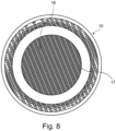
- support walls 17 and/or pillars can be provided in the hollow chamber 12 mentioned, which can form an overall honeycomb-like support structure 18 which connects the opposite body walls 13 and 14 to one another or supports them against one another.
- the support structure 18 mentioned can be integrally connected to one or both opposite body walls 13 and 14, in particular by means of a layered construction, it can be formed thereon in a material-locking manner.
- the support structure 18 mentioned can be formed layer by layer as a layered body, in particular produced by a 3D printing process.
- the support structure 18 mentioned can advantageously be produced in parallel to the layered construction of the body and/or peripheral walls 13, 14, 15 or the channel columns 16 in the 3D printing process.
- the aforementioned supporting walls 17 can be characterized by a slim wall thickness, whereby, for example, a wall thickness/wall height ratio of 1:5 or 1:7 or less can be provided.
- the support walls 17 can have a wave-shaped contour when the walls are viewed in a direction parallel to the cutter head axis.
- the wave shape can follow a substantially straight wave direction, but an arcuate wave direction can also be provided if necessary.
- the wave-shaped support walls 17 can run from one perforated plate side to an opposite perforated plate side.
- the supporting walls 17 can have a substantially parallel course to one another and/or be formed with a substantially constant gap between them.
- more than ten or more than 20 supporting walls 17 can be provided, in particular arranged in a parallel course to one another.
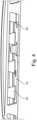
- the above-mentioned support walls 17 can each be provided with preferably window- or door-arch-shaped openings 19 through which adjacent channels between adjacent support walls are connected to one another. If a tempering fluid flows through the support structure 18, the tempering fluid can flow through the openings transversely to the support wall and be evenly distributed over the hollow chamber.
- the aforementioned openings 19 in the supporting walls 17 can advantageously be rounded in an arc shape at least in sections, in particular be rounded in an arc shape towards at least one body wall 14 or have a rounding 20.
- the supporting walls 17 can form archways around the openings 19.
- the perforated plate 8 can have inlet and outlet connections 21 and 22, via which a tempering agent, for example oil or water or a mixture for tempering the perforated plate, can be introduced into it or drained or circulated through it.
- a tempering agent for example oil or water or a mixture for tempering the perforated plate
- the tempering agent can in particular be circulated through at least part of the hollow chamber 12, wherein the support walls 17 can cause a distribution of the tempering agent.
- the perforated plate 8 can further have emptying openings 23 that can connect the hollow chamber 12 to the outside.
- the aforementioned emptying openings 22 make it possible to remove non-solidified powder from the 3D printing process from the hollow chamber 12.
- the emptying openings 23 can open onto the inlet front side of the perforated plate 8 in order to be covered when attached to the connecting body 9 of the granulating head 2.
- the perforated plate body 10 can advantageously be built on the connecting body 9 of the granulating head 2, so that the perforated plate body 10 is attached to the connecting body 9 by means of a material fit and/or by micro-form fit and/or by chemical bonding.
- the connecting body 9 can serve as a base body in the 3D printing process, onto which the material powder or the raw material is poured or applied in order to then be liquefied and solidified layer by layer.
- the perforated plate body 10 is attached directly to the The layer located on the connecting body 9 is firmly connected to the connecting body 9.
- the perforated plate body 10 can also be attached to the wear-resistant hard material ring 11 in a corresponding manner, in which case the said hard material ring can serve as a base body in the 3D printing process.
- the perforated plate body 10 can also be connected to the connection body 9 and/or the hard material ring 11 in a conventional manner, for example by soldering and/or screwing and/or pressing.
- the hard material ring 11 can be made in one piece, but can also be composed of different ring segments if necessary.
- the perforated plate body 10 does not have an interface or parting line that would pass through a melt channel.
Landscapes
- Engineering & Computer Science (AREA)
- Mechanical Engineering (AREA)
- Manufacturing & Machinery (AREA)
- Chemical & Material Sciences (AREA)
- Materials Engineering (AREA)
- Physics & Mathematics (AREA)
- Thermal Sciences (AREA)
- Processing And Handling Of Plastics And Other Materials For Molding In General (AREA)
Claims (15)
- Plaque porte-filière pour la granulation à chaud par face de filière de matières fondues, avec un corps de plaque porte-filière (10), qui présente des canaux pour matières fondues (7), qui traversent le corps de plaque porte-filière (10) et débouchent de manière répartie en une formation annulaire sur une surface de sortie (6), sur laquelle des boyaux de matières fondues sortants peuvent être décrochés à chaud par une lame rotative, dans laquelle le corps de plaque porte-filière (10) présente au moins une chambre creuse (12) pour thermoréguler la plaque porte-filière et/ou pour isoler thermiquement les canaux pour matières fondues (7) au moins en partie dans la formation annulaire du canal pour matières fondues, caractérisée en ce que le corps de plaque porte-filière (10) est réalisé en tant qu'un corps stratifié additif monobloc d'un seul tenant, dont les couches de matériau sont appliquées de manière additive et sont solidifiées individuellement couche par couche.
- Plaque porte-filière selon la revendication précédente, dans laquelle les canaux pour matières fondues (7) sont réalisés dans des colonnes de canaux (16), qui sont disposées au moins en partie librement dans la chambre creuse (12) et sont reliées de manière homogène en termes de matériaux, d'un seul tenant monobloc, à des parois de corps (13, 14) du corps de plaque porte-filière (10), qui délimitent sur des côtés opposés la chambre creuse (12), dans laquelle les colonnes de canaux (16) sont réalisées en tant que corps stratifié, dont les couches de matériaux sont solidifiées individuellement couche par couche, dans laquelle les colonnes de canaux (16) s'élargissent en direction de sections d'extrémité opposées et/ou possèdent un arrondi s'élargissant sur des sections d'extrémité opposées, qui forme une transition harmonieuse vers la paroi de corps (13, 14) respectivement adjacente, dans laquelle la paroi extérieure des colonnes de canaux (16) est réalisée de manière contre-dépouillée de manière parallèle à la direction d'écoulement de matières fondues dans deux directions axiales.
- Plaque porte-filière selon l'une quelconque des deux revendications précédentes, dans laquelle est réalisée dans la chambre creuse (12) une structure d'appui (18), qui soutient les parois de corps (13, 14) opposées, qui délimitent la chambre creuse (12), dans laquelle la structure d'appui (18) forme une formation en ondes, qui s'étend le long d'une direction de propagation des ondes depuis un côté périphérique de plaque porte-filière vers le côté périphérique de plaque porte-filière opposé, dans laquelle la structure d'appui (18) comprend des parois et/ou des flèches d'appui (17), qui sont reliées aux parois de corps (13, 14) opposées de manière homogène en termes de matériaux, d'un seul tenant monobloc et/ou y sont formées, dans laquelle les parois et/ou les flèches d'appui (17) sont élaborées en tant que corps stratifié et sont solidifiées couche par couche.
- Plaque porte-filière selon la revendication précédente, dans laquelle plus de 15 ou plus de 25 parois d'appui sont prévues ans la chambre creuse (12), dans laquelle les parois (17) et/ou les flèches d'appui sont disposées le long de lignes parallèles les unes par rapport aux autres.
- Plaque porte-filière selon l'une quelconque des deux revendications précédentes, dans laquelle les parois (17) et/ou les flèches d'appui sont pourvues d'ajours (19) en forme d'arche ou de fenêtre, dans laquelle les ajours (19) sont arrondis au moins en une paroi de corps (13, 14), qui délimite la chambre creuse (12), dans laquelle les parois (17) et/ou les flèches d'appui possèdent un rapport entre épaisseur de paroi/hauteur inférieur ou égal à 1:5.
- Plaque porte-filière selon l'une quelconque des revendications précédentes, dans laquelle le corps de plaque porte-filière (10) possède au moins une ouverture de vidange (23) pour enlever le matériau brut non solidifié hors de la chambre de creuse (12), dans laquelle l'au moins une ouverture de vidange (23) débouche sur le côté frontal côté entrée de la plaque porte-filière (2).
- Plaque porte-filière selon l'une quelconque des revendications précédentes, dans laquelle un anneau en matériau dur (11) résistant à l'usure, qui forme une contre-surface pour la lame rotative, repose sur le côté de sortie du corps de plaque porte-filière (10) et les canaux pour matières fondues (7) débouchent sur un côté extérieur de l'anneau en matériau dur (11).
- Plaque porte-filière selon la revendication précédente, dans laquelle le corps de plaque porte-filière (10) est relié à l'anneau en matériau dur (11) par liaison de matériau et/ou par micro-complémentarité de formes et/ou par liaison chimique lors de la solidification de la couche de matériau, fondue, jouxtant l'anneau en matériau dur (11), du corps stratifié.
- Tête de granulation à chaud par face (2) avec un corps de raccordement (9), sur lequel une plaque porte-filière (8) réalisée selon les revendications précédentes est fixée.
- Tête de granulation à chaud par face selon la revendication précédente, dans laquelle la plaque porte-filière (8) est reliée par liaison de matière et/ou par micro-complémentarité de formes et/ou par liaison chimique lors de la solidification de la couche de matériau fondue, jouxtant le support de raccordement (9) du corps stratifié.
- Granulateur à chaud par face avec une tête de granulation, qui est réalisée selon l'une quelconque des deux revendications précédentes.
- Granulateur à chaud par face selon la revendication précédente, dans lequel le granulateur est réalisé en tant qu'un granulateur sous-marin ou à anneau d'eau.
- Granulateur à chaud par face selon la revendication précédente, dans lequel le granulateur est réalisé en tant que granulateur à air.
- Procédé de fabrication d'une plaque porte-filière (8), qui est réalisée selon l'une quelconque des revendications 1 à 8,
caractérisé en ce que
le corps de plaque porte-filière (10) est formé par couche par application de matériau additive. - Procédé selon la revendication précédente, dans lequel le corps de plaque porte-filière (10) est formé au moyen d'une tête d'impression 3D dans le procédé d'impression 3D.
Applications Claiming Priority (2)
| Application Number | Priority Date | Filing Date | Title |
|---|---|---|---|
| DE102019127666.7A DE102019127666A1 (de) | 2019-10-15 | 2019-10-15 | Lochplatte zum Granulieren von Schmelzen sowie Verfahren zu deren Herstellung |
| PCT/EP2020/077299 WO2021073869A1 (fr) | 2019-10-15 | 2020-09-30 | Plaque porte-filière pour la granulation à chaud par face de filière de matières fondues et son procédé de production |
Publications (3)
| Publication Number | Publication Date |
|---|---|
| EP4021700A1 EP4021700A1 (fr) | 2022-07-06 |
| EP4021700C0 EP4021700C0 (fr) | 2024-11-06 |
| EP4021700B1 true EP4021700B1 (fr) | 2024-11-06 |
Family
ID=72744753
Family Applications (1)
| Application Number | Title | Priority Date | Filing Date |
|---|---|---|---|
| EP20785945.5A Active EP4021700B1 (fr) | 2019-10-15 | 2020-09-30 | Plaque porte-filière pour la granulation à chaud par face de filière de matières fondues, et procédé de fabrication associé |
Country Status (8)
| Country | Link |
|---|---|
| US (1) | US20240116217A1 (fr) |
| EP (1) | EP4021700B1 (fr) |
| JP (1) | JP7766590B2 (fr) |
| KR (1) | KR20220082881A (fr) |
| CN (1) | CN114555307B (fr) |
| DE (1) | DE102019127666A1 (fr) |
| TW (1) | TWI887280B (fr) |
| WO (1) | WO2021073869A1 (fr) |
Families Citing this family (2)
| Publication number | Priority date | Publication date | Assignee | Title |
|---|---|---|---|---|
| DE102022213951A1 (de) * | 2022-12-19 | 2024-06-20 | Cqlt Saargummi Technologies S.À.R.L. | Extrusionswerkzeug zur Herstellung eines Kunststoffbauteils, Extrudieranlage, Verfahren zur Herstellung eines Extrusionsbauteils und Extrusionsbauteil |
| WO2024142036A1 (fr) * | 2022-12-27 | 2024-07-04 | Tritone Technologies Ltd. | Tête de traitement avec outil de coupe et système de nettoyage associé |
Family Cites Families (27)
| Publication number | Priority date | Publication date | Assignee | Title |
|---|---|---|---|---|
| US4184832A (en) * | 1974-02-10 | 1980-01-22 | Leesona Corporation | Die construction |
| US4564350A (en) * | 1982-06-10 | 1986-01-14 | Thomas R. Vigil | Plastic extruder assembly |
| DE3532937A1 (de) * | 1985-09-14 | 1987-04-02 | Werner & Pfleiderer | Lochplatte fuer die unterwassergranulierung von kunststoffstraengen |
| DE4036196A1 (de) * | 1990-11-14 | 1992-05-21 | Reinecke Gmbh H | Granulierlochplatte |
| US5745834A (en) * | 1995-09-19 | 1998-04-28 | Rockwell International Corporation | Free form fabrication of metallic components |
| JPH10264151A (ja) * | 1997-03-28 | 1998-10-06 | Japan Steel Works Ltd:The | 合成樹脂用造粒ダイス |
| US6220847B1 (en) * | 1997-05-19 | 2001-04-24 | The Japan Steel Works, Ltd. | Underwater granulating die |
| US7658874B2 (en) * | 2003-07-30 | 2010-02-09 | E.I. Du Pont De Nemours And Company | Polymer pelletization process and apparatus |
| US7524179B2 (en) * | 2005-01-25 | 2009-04-28 | Gala Industries, Inc. | Center heated die plate with two heat zones for underwater pelletizer |
| US7402034B2 (en) * | 2005-01-25 | 2008-07-22 | Gala Industries, Inc. | Center heated die plate for underwater pelletizer |
| DE102006026967A1 (de) * | 2006-06-09 | 2007-12-13 | Rolls-Royce Deutschland Ltd & Co Kg | Verfahren zur Herstellung eines Zerspanwerkzeugs |
| DE202006018455U1 (de) * | 2006-12-05 | 2007-02-15 | C.F. Scheer & Cie. Gmbh & Co. | Düsenplatte für Stranggranulieranlage |
| US20100040716A1 (en) * | 2008-08-13 | 2010-02-18 | Fridley Michael A | Thermally insulated die plate assembly for underwater pelletizing and the like |
| AT508199B1 (de) | 2008-12-16 | 2011-05-15 | Erema | Vorrichtung zur heissabschlag-granulierung |
| DE102011018403A1 (de) | 2011-04-21 | 2012-10-25 | Automatik Plastics Machinery Gmbh | Verfahren zur Herstellung von pharmazeutischen Erzeugnissen aus einem Schmelzematerial |
| DE102012012070A1 (de) * | 2012-06-15 | 2013-12-19 | Automatik Plastics Machinery Gmbh | Düsenplatte für eine Granuliervorrichtung und Granuliervorrichtung mit einer Düsenplatte |
| US10076860B2 (en) * | 2013-09-29 | 2018-09-18 | Husky Injection Molding Systems Ltd. | Unitary monolithically formed injection-molding apparatuses |
| US9481121B2 (en) * | 2013-11-08 | 2016-11-01 | Kennametal Inc. | Extrusion die plate assembly for a pelletizer system |
| US10124523B2 (en) * | 2014-11-20 | 2018-11-13 | Gala Industries, Inc. | Die plate with die plate body having an apertured downstream face covered by a solid face plate |
| JP6549435B2 (ja) * | 2015-07-16 | 2019-07-24 | 株式会社キャステム | 粉末プレス成形体の製造方法 |
| BE1023722B1 (de) * | 2015-11-13 | 2017-06-27 | Inexco Europe | Extrusionswerkzeug |
| DE102015225344A1 (de) * | 2015-12-15 | 2017-06-22 | Eos Gmbh Electro Optical Systems | Pulveraustragseinheit, Vorrichtung und Verfahren zum generativen Herstellen eines dreidimensionalen Objekts |
| US20170252851A1 (en) * | 2016-03-02 | 2017-09-07 | Desktop Metal, Inc. | Additive manufacturing with metallic composites |
| DE102016124387A1 (de) * | 2016-11-15 | 2018-05-17 | R. Scheuchl Gmbh | Baubox zur additiven Herstellung eines Formteils und Anordnung |
| DE102017003926A1 (de) * | 2017-04-24 | 2018-10-25 | Heinz Gross | Extrusionsvorrichtung zur Minimierung des thermischen Abbaus von Schmelzen |
| CN110103350A (zh) * | 2018-02-01 | 2019-08-09 | 易康有限公司 | 成粒头-板件和用于制造成粒头-板件的方法 |
| CN110202771A (zh) | 2018-02-07 | 2019-09-06 | 大连市锐耐特刀具有限公司 | 一种造粒模板用真空隔热盖板 |
-
2019
- 2019-10-15 DE DE102019127666.7A patent/DE102019127666A1/de not_active Ceased
-
2020
- 2020-09-30 EP EP20785945.5A patent/EP4021700B1/fr active Active
- 2020-09-30 US US17/769,201 patent/US20240116217A1/en active Pending
- 2020-09-30 JP JP2022522849A patent/JP7766590B2/ja active Active
- 2020-09-30 KR KR1020227016054A patent/KR20220082881A/ko active Pending
- 2020-09-30 CN CN202080070305.3A patent/CN114555307B/zh active Active
- 2020-09-30 WO PCT/EP2020/077299 patent/WO2021073869A1/fr not_active Ceased
- 2020-10-14 TW TW109135523A patent/TWI887280B/zh active
Also Published As
| Publication number | Publication date |
|---|---|
| TW202128384A (zh) | 2021-08-01 |
| TWI887280B (zh) | 2025-06-21 |
| DE102019127666A1 (de) | 2021-04-15 |
| US20240116217A1 (en) | 2024-04-11 |
| KR20220082881A (ko) | 2022-06-17 |
| CN114555307A (zh) | 2022-05-27 |
| JP7766590B2 (ja) | 2025-11-10 |
| WO2021073869A1 (fr) | 2021-04-22 |
| EP4021700C0 (fr) | 2024-11-06 |
| JP2022553196A (ja) | 2022-12-22 |
| EP4021700A1 (fr) | 2022-07-06 |
| CN114555307B (zh) | 2025-03-11 |
Similar Documents
| Publication | Publication Date | Title |
|---|---|---|
| DE4106964C2 (de) | Vorrichtung und Verfahren zum Herstellen von Formhäuten und -körpern aus Kunststoff | |
| EP2655037B1 (fr) | Buse de canal chaud et son procede de fabrication | |
| DE2543450A1 (de) | Vorrichtung zum granulieren von thermoplastischen kunststoffen | |
| DE10317357B4 (de) | Extruder | |
| EP4021700B1 (fr) | Plaque porte-filière pour la granulation à chaud par face de filière de matières fondues, et procédé de fabrication associé | |
| DE1273788B (de) | Granuliervorrichtung fuer thermoplastische Kunststoffe | |
| DE2320891A1 (de) | Pressmatrize fuer das unterwassertablettieren | |
| EP1980380A1 (fr) | Dispositif de chauffage ou de refroidissement, en particulier comme partie d'un moule destiné au traitement de matières plastiques, tel qu' un moule d'injection pour plastique. | |
| DE3513536C1 (fr) | ||
| EP0449978A1 (fr) | Procede de fabrication de pieces moulees en plastique. | |
| EP1777479B1 (fr) | Corps métallique avec agencement de canaux pour régler la température d'un moule d'injection ou de coulage formé par ledit corps métallique | |
| DE69609910T2 (de) | Niederdruckgiessanlage für Fahrzeugräder | |
| AT405181B (de) | Verfahren und vorrichtung zum mischen oder thermischen homogenisieren von zumindest einem fluid | |
| EP2136982B1 (fr) | Moule et procédé pour la fabrication de peaux et de corps moulés en plastique | |
| DE19929333C1 (de) | Verfahren zum Herstellen einer Vulkanisationsform für Fahrzeugreifen und Vulkanisationsform für Fahrzeugreifen | |
| EP3088153B1 (fr) | Outil de formage | |
| DE4036196A1 (de) | Granulierlochplatte | |
| AT505894B1 (de) | Granuliervorrichtung und granulierlochplatte | |
| EP3439847B1 (fr) | Vis sans fin à thermorégulation interne, installation et procédé de mise en oeuvre d'une telle vis sans fin | |
| EP4342649B1 (fr) | Procédé de fabrication d'une pièce moulée | |
| WO2003097318A2 (fr) | Dispositif de moulage pour realiser des membranes plastiques moulees | |
| DE1779662B2 (de) | Verfahren und vorrichtung zum herstellen eines schaumstoffgegenstandes aus einem thermoplastischen treibmittelhaltigen kunststoff | |
| WO2019148225A1 (fr) | Plaque pour tête de granulation et procédé de fabrication d'une plaque pour tête de granulation | |
| AT3267U1 (de) | Verfahren und vorrichtung zum mischen oder thermischen homogenisieren von zumindest einem fluid |
Legal Events
| Date | Code | Title | Description |
|---|---|---|---|
| STAA | Information on the status of an ep patent application or granted ep patent |
Free format text: STATUS: UNKNOWN |
|
| STAA | Information on the status of an ep patent application or granted ep patent |
Free format text: STATUS: THE INTERNATIONAL PUBLICATION HAS BEEN MADE |
|
| PUAI | Public reference made under article 153(3) epc to a published international application that has entered the european phase |
Free format text: ORIGINAL CODE: 0009012 |
|
| STAA | Information on the status of an ep patent application or granted ep patent |
Free format text: STATUS: REQUEST FOR EXAMINATION WAS MADE |
|
| 17P | Request for examination filed |
Effective date: 20220330 |
|
| AK | Designated contracting states |
Kind code of ref document: A1 Designated state(s): AL AT BE BG CH CY CZ DE DK EE ES FI FR GB GR HR HU IE IS IT LI LT LU LV MC MK MT NL NO PL PT RO RS SE SI SK SM TR |
|
| DAV | Request for validation of the european patent (deleted) | ||
| DAX | Request for extension of the european patent (deleted) | ||
| GRAP | Despatch of communication of intention to grant a patent |
Free format text: ORIGINAL CODE: EPIDOSNIGR1 |
|
| STAA | Information on the status of an ep patent application or granted ep patent |
Free format text: STATUS: GRANT OF PATENT IS INTENDED |
|
| RIC1 | Information provided on ipc code assigned before grant |
Ipc: B33Y 80/00 20150101ALN20240524BHEP Ipc: B29C 48/04 20190101ALN20240524BHEP Ipc: B22F 5/10 20060101ALI20240524BHEP Ipc: B29C 48/345 20190101ALI20240524BHEP Ipc: B29C 48/30 20190101ALI20240524BHEP Ipc: B29C 48/05 20190101ALI20240524BHEP Ipc: B29C 48/00 20190101ALI20240524BHEP Ipc: B29B 7/82 20060101ALI20240524BHEP Ipc: B29B 7/58 20060101ALI20240524BHEP Ipc: B29B 9/06 20060101AFI20240524BHEP |
|
| INTG | Intention to grant announced |
Effective date: 20240611 |
|
| GRAS | Grant fee paid |
Free format text: ORIGINAL CODE: EPIDOSNIGR3 |
|
| GRAA | (expected) grant |
Free format text: ORIGINAL CODE: 0009210 |
|
| STAA | Information on the status of an ep patent application or granted ep patent |
Free format text: STATUS: THE PATENT HAS BEEN GRANTED |
|
| AK | Designated contracting states |
Kind code of ref document: B1 Designated state(s): AL AT BE BG CH CY CZ DE DK EE ES FI FR GB GR HR HU IE IS IT LI LT LU LV MC MK MT NL NO PL PT RO RS SE SI SK SM TR |
|
| REG | Reference to a national code |
Ref country code: GB Ref legal event code: FG4D Free format text: NOT ENGLISH |
|
| REG | Reference to a national code |
Ref country code: CH Ref legal event code: EP |
|
| REG | Reference to a national code |
Ref country code: DE Ref legal event code: R096 Ref document number: 502020009718 Country of ref document: DE |
|
| REG | Reference to a national code |
Ref country code: IE Ref legal event code: FG4D Free format text: LANGUAGE OF EP DOCUMENT: GERMAN |
|
| U01 | Request for unitary effect filed |
Effective date: 20241106 |
|
| U07 | Unitary effect registered |
Designated state(s): AT BE BG DE DK EE FI FR IT LT LU LV MT NL PT RO SE SI Effective date: 20241113 |
|
| PG25 | Lapsed in a contracting state [announced via postgrant information from national office to epo] |
Ref country code: HR Free format text: LAPSE BECAUSE OF FAILURE TO SUBMIT A TRANSLATION OF THE DESCRIPTION OR TO PAY THE FEE WITHIN THE PRESCRIBED TIME-LIMIT Effective date: 20241106 Ref country code: IS Free format text: LAPSE BECAUSE OF FAILURE TO SUBMIT A TRANSLATION OF THE DESCRIPTION OR TO PAY THE FEE WITHIN THE PRESCRIBED TIME-LIMIT Effective date: 20250306 |
|
| PG25 | Lapsed in a contracting state [announced via postgrant information from national office to epo] |
Ref country code: ES Free format text: LAPSE BECAUSE OF FAILURE TO SUBMIT A TRANSLATION OF THE DESCRIPTION OR TO PAY THE FEE WITHIN THE PRESCRIBED TIME-LIMIT Effective date: 20241106 |
|
| PG25 | Lapsed in a contracting state [announced via postgrant information from national office to epo] |
Ref country code: NO Free format text: LAPSE BECAUSE OF FAILURE TO SUBMIT A TRANSLATION OF THE DESCRIPTION OR TO PAY THE FEE WITHIN THE PRESCRIBED TIME-LIMIT Effective date: 20250206 |
|
| PG25 | Lapsed in a contracting state [announced via postgrant information from national office to epo] |
Ref country code: GR Free format text: LAPSE BECAUSE OF FAILURE TO SUBMIT A TRANSLATION OF THE DESCRIPTION OR TO PAY THE FEE WITHIN THE PRESCRIBED TIME-LIMIT Effective date: 20250207 |
|
| PG25 | Lapsed in a contracting state [announced via postgrant information from national office to epo] |
Ref country code: PL Free format text: LAPSE BECAUSE OF FAILURE TO SUBMIT A TRANSLATION OF THE DESCRIPTION OR TO PAY THE FEE WITHIN THE PRESCRIBED TIME-LIMIT Effective date: 20241106 |
|
| PG25 | Lapsed in a contracting state [announced via postgrant information from national office to epo] |
Ref country code: RS Free format text: LAPSE BECAUSE OF FAILURE TO SUBMIT A TRANSLATION OF THE DESCRIPTION OR TO PAY THE FEE WITHIN THE PRESCRIBED TIME-LIMIT Effective date: 20250206 |
|
| PG25 | Lapsed in a contracting state [announced via postgrant information from national office to epo] |
Ref country code: SM Free format text: LAPSE BECAUSE OF FAILURE TO SUBMIT A TRANSLATION OF THE DESCRIPTION OR TO PAY THE FEE WITHIN THE PRESCRIBED TIME-LIMIT Effective date: 20241106 |
|
| PG25 | Lapsed in a contracting state [announced via postgrant information from national office to epo] |
Ref country code: SK Free format text: LAPSE BECAUSE OF FAILURE TO SUBMIT A TRANSLATION OF THE DESCRIPTION OR TO PAY THE FEE WITHIN THE PRESCRIBED TIME-LIMIT Effective date: 20241106 |
|
| PG25 | Lapsed in a contracting state [announced via postgrant information from national office to epo] |
Ref country code: CZ Free format text: LAPSE BECAUSE OF FAILURE TO SUBMIT A TRANSLATION OF THE DESCRIPTION OR TO PAY THE FEE WITHIN THE PRESCRIBED TIME-LIMIT Effective date: 20241106 |
|
| PLBE | No opposition filed within time limit |
Free format text: ORIGINAL CODE: 0009261 |
|
| STAA | Information on the status of an ep patent application or granted ep patent |
Free format text: STATUS: NO OPPOSITION FILED WITHIN TIME LIMIT |
|
| 26N | No opposition filed |
Effective date: 20250807 |
|
| PGFP | Annual fee paid to national office [announced via postgrant information from national office to epo] |
Ref country code: TR Payment date: 20250923 Year of fee payment: 6 |
|
| PGFP | Annual fee paid to national office [announced via postgrant information from national office to epo] |
Ref country code: GB Payment date: 20250919 Year of fee payment: 6 |
|
| U20 | Renewal fee for the european patent with unitary effect paid |
Year of fee payment: 6 Effective date: 20250924 |
|
| U1N | Appointed representative for the unitary patent procedure changed after the registration of the unitary effect |
Representative=s name: LORENZ SEIDLER GOSSEL PART. MBB; DE |