EP4022826B1 - Activation et deactivation d'etat de l'indicator de configuration de transmission - Google Patents
Activation et deactivation d'etat de l'indicator de configuration de transmission Download PDFInfo
- Publication number
- EP4022826B1 EP4022826B1 EP20768488.7A EP20768488A EP4022826B1 EP 4022826 B1 EP4022826 B1 EP 4022826B1 EP 20768488 A EP20768488 A EP 20768488A EP 4022826 B1 EP4022826 B1 EP 4022826B1
- Authority
- EP
- European Patent Office
- Prior art keywords
- activation status
- activation
- status message
- spatial relationships
- tci states
- Prior art date
- Legal status (The legal status is an assumption and is not a legal conclusion. Google has not performed a legal analysis and makes no representation as to the accuracy of the status listed.)
- Active
Links
Images






Classifications
-
- H—ELECTRICITY
- H04—ELECTRIC COMMUNICATION TECHNIQUE
- H04L—TRANSMISSION OF DIGITAL INFORMATION, e.g. TELEGRAPHIC COMMUNICATION
- H04L5/00—Arrangements affording multiple use of the transmission path
- H04L5/003—Arrangements for allocating sub-channels of the transmission path
- H04L5/0053—Allocation of signalling, i.e. of overhead other than pilot signals
-
- H—ELECTRICITY
- H04—ELECTRIC COMMUNICATION TECHNIQUE
- H04L—TRANSMISSION OF DIGITAL INFORMATION, e.g. TELEGRAPHIC COMMUNICATION
- H04L5/00—Arrangements affording multiple use of the transmission path
- H04L5/0001—Arrangements for dividing the transmission path
- H04L5/0003—Two-dimensional division
- H04L5/0005—Time-frequency
- H04L5/0007—Time-frequency the frequencies being orthogonal, e.g. OFDM(A) or DMT
- H04L5/001—Time-frequency the frequencies being orthogonal, e.g. OFDM(A) or DMT the frequencies being arranged in component carriers
-
- H—ELECTRICITY
- H04—ELECTRIC COMMUNICATION TECHNIQUE
- H04L—TRANSMISSION OF DIGITAL INFORMATION, e.g. TELEGRAPHIC COMMUNICATION
- H04L5/00—Arrangements affording multiple use of the transmission path
- H04L5/0001—Arrangements for dividing the transmission path
- H04L5/0014—Three-dimensional division
- H04L5/0023—Time-frequency-space
-
- H—ELECTRICITY
- H04—ELECTRIC COMMUNICATION TECHNIQUE
- H04L—TRANSMISSION OF DIGITAL INFORMATION, e.g. TELEGRAPHIC COMMUNICATION
- H04L5/00—Arrangements affording multiple use of the transmission path
- H04L5/003—Arrangements for allocating sub-channels of the transmission path
- H04L5/0048—Allocation of pilot signals, i.e. of signals known to the receiver
-
- H—ELECTRICITY
- H04—ELECTRIC COMMUNICATION TECHNIQUE
- H04L—TRANSMISSION OF DIGITAL INFORMATION, e.g. TELEGRAPHIC COMMUNICATION
- H04L5/00—Arrangements affording multiple use of the transmission path
- H04L5/0091—Signalling for the administration of the divided path, e.g. signalling of configuration information
- H04L5/0096—Indication of changes in allocation
- H04L5/0098—Signalling of the activation or deactivation of component carriers, subcarriers or frequency bands
-
- H—ELECTRICITY
- H04—ELECTRIC COMMUNICATION TECHNIQUE
- H04W—WIRELESS COMMUNICATION NETWORKS
- H04W24/00—Supervisory, monitoring or testing arrangements
- H04W24/10—Scheduling measurement reports ; Arrangements for measurement reports
-
- H—ELECTRICITY
- H04—ELECTRIC COMMUNICATION TECHNIQUE
- H04W—WIRELESS COMMUNICATION NETWORKS
- H04W72/00—Local resource management
- H04W72/04—Wireless resource allocation
- H04W72/044—Wireless resource allocation based on the type of the allocated resource
- H04W72/0453—Resources in frequency domain, e.g. a carrier in FDMA
-
- H—ELECTRICITY
- H04—ELECTRIC COMMUNICATION TECHNIQUE
- H04W—WIRELESS COMMUNICATION NETWORKS
- H04W72/00—Local resource management
- H04W72/20—Control channels or signalling for resource management
- H04W72/23—Control channels or signalling for resource management in the downlink direction of a wireless link, i.e. towards a terminal
-
- H—ELECTRICITY
- H04—ELECTRIC COMMUNICATION TECHNIQUE
- H04W—WIRELESS COMMUNICATION NETWORKS
- H04W8/00—Network data management
- H04W8/22—Processing or transfer of terminal data, e.g. status or physical capabilities
- H04W8/24—Transfer of terminal data
Definitions
- aspects of the present disclosure generally relate to wireless communication and to techniques and apparatuses for transmission configuration indicator state activation and deactivation.
- Wireless communication systems are widely deployed to provide various telecommunication services such as telephony, video, data, messaging, and broadcasts.
- Typical wireless communication systems may employ multiple-access technologies capable of supporting communication with multiple users by sharing available system resources (e.g., bandwidth, transmit power, and/or the like).
- multiple-access technologies include code division multiple access (CDMA) systems, time division multiple access (TDMA) systems, frequency-division multiple access (FDMA) systems, orthogonal frequency-division multiple access (OFDMA) systems, single-carrier frequency-division multiple access (SC-FDMA) systems, time division synchronous code division multiple access (TD-SCDMA) systems, and Long Term Evolution (LTE).
- LTE/LTE-Advanced is a set of enhancements to the Universal Mobile Telecommunications System (UMTS) mobile standard promulgated by the Third Generation Partnership Project (3GPP).
- UMTS Universal Mobile Telecommunications System
- a wireless communication network may include a number of base stations (BSs) that can support communication for a number of user equipment (UEs).
- a user equipment (UE) may communicate with a base station (BS) via the downlink and uplink.
- the downlink (or forward link) refers to the communication link from the BS to the UE
- the uplink (or reverse link) refers to the communication link from the UE to the BS.
- a BS may be referred to as a Node B, a gNB, an access point (AP), a radio head, a transmit receive point (TRP), a New Radio (NR) BS, a 5G Node B, and/or the like.
- New Radio which may also be referred to as 5G, is a set of enhancements to the LTE mobile standard promulgated by the Third Generation Partnership Project (3GPP).
- 3GPP Third Generation Partnership Project
- NR is designed to better support mobile broadband Internet access by improving spectral efficiency, lowering costs, improving services, making use of new spectrum, and better integrating with other open standards using orthogonal frequency division multiplexing (OFDM) with a cyclic prefix (CP) (CP-OFDM) on the downlink (DL), using CP-OFDM and/or SC-FDM (e.g., also known as discrete Fourier transform spread OFDM (DFT-s-OFDM)) on the uplink (UL), as well as supporting beamforming, multiple-input multiple-output (MIMO) antenna technology, and carrier aggregation.
- OFDM orthogonal frequency division multiplexing
- SC-FDM e.g., also known as discrete Fourier transform spread OFDM (DFT-s-OFDM)
- MIMO multiple-input multiple-output
- document 3GPP R1-1806217 describes beam measurement and reporting while document US 2019/0254110 describes a method to reduce power consumption in response to an outcome of a signal reception.
- a method performed by a user equipment (UE) and relative computer program and apparatus of wireless communication are defined in the appended independent claims, while optionally aspects thereof are indicated in the dependent claims.
- aspects generally include a method, apparatus, system, computer program product, non-transitory computer-readable medium, user equipment, base station, wireless communication device, and/or processing system as substantially described herein with reference to and as illustrated by the accompanying drawings and specification.
- Fig. 1 is a diagram illustrating a wireless network 100 in which aspects of the present disclosure may be practiced.
- the wireless network 100 may be an LTE network or some other wireless network, such as a 5G or NR network.
- the wireless network 100 may include a number of BSs 110 (shown as BS 110a, BS 110b, BS 110c, and BS 110d) and other network entities.
- a BS is an entity that communicates with user equipment (UEs) and may also be referred to as a base station, a NR BS, a Node B, a gNB, a 5G node B (NB), an access point, a transmit receive point (TRP), and/or the like.
- Each BS may provide communication coverage for a particular geographic area.
- the term "cell" can refer to a coverage area of a BS and/or a BS subsystem serving this coverage area, depending on the context in which the term is used.
- a BS may provide communication coverage for a macro cell, a pico cell, a femto cell, and/or another type of cell.
- a macro cell may cover a relatively large geographic area (e.g., several kilometers in radius) and may allow unrestricted access by UEs with service subscription.
- a pico cell may cover a relatively small geographic area and may allow unrestricted access by UEs with service subscription.
- a femto cell may cover a relatively small geographic area (e.g., a home) and may allow restricted access by UEs having association with the femto cell (e.g., UEs in a closed subscriber group (CSG)).
- a BS for a macro cell may be referred to as a macro BS.
- a BS for a pico cell may be referred to as a pico BS.
- a BS for a femto cell may be referred to as a femto BS or a home BS.
- a BS 110a may be a macro BS for a macro cell 102a
- a BS 110b may be a pico BS for a pico cell 102b
- a BS 110c may be a femto BS for a femto cell 102c.
- a BS may support one or multiple (e.g., three) cells.
- the terms "eNB”, “base station”, “NR BS”, “gNB”, “TRP”, “AP”, “node B", “5G NB”, and “cell” may be used interchangeably herein.
- a cell may not necessarily be stationary, and the geographic area of the cell may move according to the location of a mobile BS.
- the BSs may be interconnected to one another and/or to one or more other BSs or network nodes (not shown) in the wireless network 100 through various types of backhaul interfaces such as a direct physical connection, a virtual network, and/or the like using any suitable transport network.
- Wireless network 100 may also include relay stations.
- a relay station is an entity that can receive a transmission of data from an upstream station (e.g., a BS or a UE) and send a transmission of the data to a downstream station (e.g., a UE or a BS).
- a relay station may also be a UE that can relay transmissions for other UEs.
- a relay station 110d may communicate with macro BS 110a and a UE 120d in order to facilitate communication between BS 110a and UE 120d.
- a relay station may also be referred to as a relay BS, a relay base station, a relay, and/or the like.
- Wireless network 100 may be a heterogeneous network that includes BSs of different types, e.g., macro BSs, pico BSs, femto BSs, relay BSs, and/or the like. These different types of BSs may have different transmit power levels, different coverage areas, and different impacts on interference in wireless network 100.
- macro BSs may have a high transmit power level (e.g., 5 to 40 watts) whereas pico BSs, femto BSs, and relay BSs may have lower transmit power levels (e.g., 0.1 to 2 watts).
- a network controller 130 may couple to a set of BSs and may provide coordination and control for these BSs.
- Network controller 130 may communicate with the BSs via a backhaul.
- the BSs may also communicate with one another, e.g., directly or indirectly via a wireless or wireline backhaul.
- UEs 120 may be dispersed throughout wireless network 100, and each UE may be stationary or mobile.
- a UE may also be referred to as an access terminal, a terminal, a mobile station, a subscriber unit, a station, and/or the like.
- a UE may be a cellular phone (e.g., a smart phone), a personal digital assistant (PDA), a wireless modem, a wireless communication device, a handheld device, a laptop computer, a cordless phone, a wireless local loop (WLL) station, a tablet, a camera, a gaming device, a netbook, a smartbook, an ultrabook, a medical device or equipment, biometric sensors/devices, wearable devices (smart watches, smart clothing, smart glasses, smart wrist bands, smart jewelry (e.g., smart ring, smart bracelet)), an entertainment device (e.g., a music or video device, or a satellite radio), a vehicular component or sensor, smart meters/sensors, industrial manufacturing equipment, a global positioning system device, or any other suitable device that is configured to communicate via a wireless or wired medium.
- a cellular phone e.g., a smart phone
- PDA personal digital assistant
- WLL wireless local loop
- MTC and eMTC UEs include, for example, robots, drones, remote devices, sensors, meters, monitors, location tags, and/or the like, that may communicate with a base station, another device (e.g., remote device), or some other entity.
- a wireless node may provide, for example, connectivity for or to a network (e.g., a wide area network such as Internet or a cellular network) via a wired or wireless communication link.
- Some UEs may be considered Internet-of-Things (IoT) devices, and/or may be implemented as NB-IoT (narrowband internet of things) devices.
- Some UEs may be considered a Customer Premises Equipment (CPE).
- UE 120 may be included inside a housing that houses components of UE 120, such as processor components, memory components, and/or the like.
- any number of wireless networks may be deployed in a given geographic area.
- Each wireless network may support a particular RAT and may operate on one or more frequencies.
- a RAT may also be referred to as a radio technology, an air interface, and/or the like.
- a frequency may also be referred to as a carrier, a frequency channel, and/or the like.
- Each frequency may support a single RAT in a given geographic area in order to avoid interference between wireless networks of different RATs.
- NR or 5G RAT networks may be deployed.
- two or more UEs 120 may communicate directly using one or more sidelink channels (e.g., without using a base station 110 as an intermediary to communicate with one another).
- the UEs 120 may communicate using peer-to-peer (P2P) communications, device-to-device (D2D) communications, a vehicle-to-everything (V2X) protocol (e.g., which may include a vehicle-to-vehicle (V2V) protocol, a vehicle-to-infrastructure (V2I) protocol, and/or the like), a mesh network, and/or the like).
- V2X vehicle-to-everything
- the UE 120 may perform scheduling operations, resource selection operations, and/or other operations described elsewhere herein as being performed by the base station 110.
- Fig. 2 shows a block diagram of a design 200 of base station 110 and UE 120, which may be one of the base stations and one of the UEs in Fig. 1 .
- Base station 110 may be equipped with T antennas 234a through 234t
- UE 120 may be equipped with R antennas 252a through 252r, where in general T ⁇ 1 and R ⁇ 1.
- Transmit processor 220 may also generate reference symbols for reference signals (e.g., the cell-specific reference signal (CRS)) and synchronization signals (e.g., the primary synchronization signal (PSS) and secondary synchronization signal (SSS)).
- a transmit (TX) multiple-input multiple-output (MIMO) processor 230 may perform spatial processing (e.g., precoding) on the data symbols, the control symbols, the overhead symbols, and/or the reference symbols, if applicable, and may provide T output symbol streams to T modulators (MODs) 232a through 232t. Each modulator 232 may process a respective output symbol stream (e.g., for OFDM and/or the like) to obtain an output sample stream.
- Each modulator 232 may further process (e.g., convert to analog, amplify, filter, and upconvert) the output sample stream to obtain a downlink signal.
- T downlink signals from modulators 232a through 232t may be transmitted via T antennas 234a through 234t, respectively.
- the synchronization signals can be generated with location encoding to convey additional information.
- antennas 252a through 252r may receive the downlink signals from base station 110 and/or other base stations and may provide received signals to demodulators (DEMODs) 254a through 254r, respectively.
- Each demodulator 254 may condition (e.g., filter, amplify, downconvert, and digitize) a received signal to obtain input samples.
- Each demodulator 254 may further process the input samples (e.g., for OFDM and/or the like) to obtain received symbols.
- a MIMO detector 256 may obtain received symbols from all R demodulators 254a through 254r, perform MIMO detection on the received symbols if applicable, and provide detected symbols.
- a transmit processor 264 may receive and process data from a data source 262 and control information (e.g., for reports comprising RSRP, RSSI, RSRQ, CQI, and/or the like) from controller/processor 280. Transmit processor 264 may also generate reference symbols for one or more reference signals. The symbols from transmit processor 264 may be precoded by a TX MIMO processor 266 if applicable, further processed by modulators 254a through 254r (e.g., for DFT-s-OFDM, CP-OFDM, and/or the like), and transmitted to base station 110.
- control information e.g., for reports comprising RSRP, RSSI, RSRQ, CQI, and/or the like
- Transmit processor 264 may also generate reference symbols for one or more reference signals.
- the symbols from transmit processor 264 may be precoded by a TX MIMO processor 266 if applicable, further processed by modulators 254a through 254r (e.g., for DFT-
- memory 242 and/or memory 282 may comprise a non-transitory computer-readable medium storing one or more instructions for wireless communication.
- the one or more instructions when executed by one or more processors of the base station 110 and/or the UE 120, may perform or direct operations of, for example, process 400 of Fig. 4 and/or other processes as described herein.
- a scheduler 246 may schedule UEs for data transmission on the downlink and/or uplink.
- UE 120 may include means for receiving an activation status message identifying one or more TCI states or one or more spatial relationships, the activation status message being configured to alter one or more activation statuses for the one or more TCI states or the one or more spatial relationships in a single bandwidth part associated with a single component carrier, means for selectively altering the one or more activation statuses of the one or more TCI states or the one or more spatial relationships in a plurality of bandwidth parts associated with a plurality of component carriers based at least in part on receiving the activation status message, and/or the like.
- such means may include one or more components of UE 120 described in connection with Fig. 2 , such as controller/processor 280, transmit processor 264, TX MIMO processor 266, MOD 254, antenna 252, DEMOD 254, MIMO detector 256, receive processor 258, and/or the like.
- Fig. 2 is provided as an example. Other examples may differ from what is described with regard to Fig. 2 .
- a UE may have a plurality of bandwidth parts that the UE may use for communication.
- the UE may communicate with a BS using a plurality of component carriers, and each component carrier may have a plurality of bandwidth parts that are defined for the component carrier.
- Each bandwidth part may have a plurality of defined TCI states.
- a UE may have a first component carrier with a first bandwidth part and a second bandwidth part, and the first bandwidth part may have a first TCI state and a second TCI state defined, and the second bandwidth part may have a third TCI state and a fourth TCI state defined.
- the UE may have a second component carrier with a third bandwidth part and a fourth bandwidth part, and the third bandwidth part may have the first TCI state and the second TCI state defined, and the fourth bandwidth part may have the third TCI state and the fourth TCI state defined.
- the TCI states define parameters for receiving and/or transmitting on a bandwidth part.
- a UE may use a TCI state to determine a set of parameters with which a BS transmits a downlink signal, which may enable the UE to receive the downlink signal.
- Information identified based at least in part on a TCI may include quasi-co-location (QCL) information, beam identification information, and/or the like.
- QCL quasi-co-location
- a UE may be configured with, for example, up to 128 TCI states, which may be in an active state, an inactive state, and/or the like.
- the UE For reception of a downlink channel, such as a physical downlink shared channel (PDSCH) or a physical downlink control channel (PDCCH), the UE may select an active TCI state to apply to the downlink channel to enable the UE to receive the channel.
- a downlink channel such as a physical downlink shared channel (PDSCH) or a physical downlink control channel (PDCCH)
- the UE may select an active TCI state to apply to the downlink channel to enable the UE to receive the channel.
- a BS may transmit multiple transmissions to activate the same TCI state on multiple bandwidth parts of multiple component carriers in a single band. When bandwidth parts are in the same band, channel properties may be similar, which may result in the TCI state having the same activation status on multiple different bandwidth parts.
- a UE may receive, from a BS, an activation status message that identifies an alteration to one or more activation statuses of one or more TCI states or one or more spatial relationships in a single bandwidth part of a single component carrier.
- the UE may receive an activation status indicator (e.g., which may be a field of the activation status message) that may indicate whether to apply the activation status message to a plurality of bandwidth parts of a plurality of component carriers in the same band as an identified bandwidth part of the activation status message.
- an activation status indicator e.g., which may be a field of the activation status message
- the UE may determine to activate or deactivate, for example, a particular TCI state in a plurality of bandwidth parts in which the particular TCI state is defined.
- the BS and the UE may reduce a utilization of network resources, relative to separately indicating the alteration to the activation status of the particular TCI state for each bandwidth part for which the particular TCI state is defined.
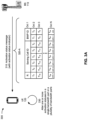
- Figs. 3A-3D are diagrams illustrating an example 300 of TCI state activation and deactivation, in accordance with various aspects of the present disclosure. As shown in Figs. 3A-3D , example 300 includes a BS 110 and a UE 120.
- UE 120 may receive an activation status message, which may include an activation status indicator.
- BS 110 may provide an activation status message that identifies one or more TCI states, one or more spatial relationships, and/or the like for a single bandwidth part and includes a field set to indicate whether the activation status message is to apply to a plurality of bandwidth parts.
- UE 120 may receive an activation status message separate from the activation status indicator. For example, UE 120 may receive the activation status indicator via a separate transmission that occurs before the activation status message, concurrent with the activation status message, after the activation status message, and/or the like.
- BS 110 determines a value for the activation status indicator based at least in part on receiving a UE capability indicator from UE 120.
- UE 120 provides the UE capability indicator to indicate whether UE 120 is capable of applying an activation status message for a single bandwidth part to a plurality of bandwidth parts in the same frequency band.
- BS 110 may convey the activation status indicator via a particular type of message.
- BS 110 may set a radio resource control (RRC) configured flag or a bit indicator in a downlink control information (DCI) or a medium access control (MAC) control element (CE) (MAC CE).
- RRC radio resource control
- DCI downlink control information
- CE medium access control element
- a MAC CE activation status message may include a set of octets ( Oct 1 through Oct N ) including information identifying a serving cell of BS 110 ( Serving Cell ID ), a bandwidth part to which the activation status message applies ( BWP ID ), and an activation status of a set of TCI states defined for the bandwidth part ( T 0 to T (N-2) *8 + 7 ).
- the activation status message may include a reserved bit (R) that is set to indicate whether the TCI state activations or deactivations (e.g., the values for the activation statuses of the set of TCI states) for the bandwidth part are to apply to one or more other bandwidth parts in the same frequency band.
- R reserved bit
- the activation status message may include a set of octets including information identifying the serving cell, the bandwidth part, a semi-persistent (SP) channel state information (CSI) reference signal (RS) resource set, an SP CSI interference measurement (IM) resource set, and a set of TCI states.
- the activation status message includes a set of reserved bits to indicate whether the activation status message applies to a single bandwidth part or a plurality of bandwidth parts for a change to an activation status of, for example, the CSI-RS resource set, the CSI-IM resource set, the set of TCI states, and/or the like.
- the activation status message may include information for an alteration to an activation status of a spatial relationship.
- the activation status message may include a reserved bit ( R ) to indicate whether the activation status message applies to spatial relationships in a plurality of bandwidth parts in the same frequency band as an identified bandwidth part and information identifying a plurality of resource set identifiers ( Resource ID ) from which UE 120 can derive a spatial relationship.
- the activation status message includes a field to indicate whether an SP sounding reference signal (SRS) set is to be activated or deactivated ( SP SRS Resource Set ID ) in a single bandwidth part or, based on the activation status indicator, a plurality of bandwidth parts.
- the spatial relationship may include a relation between a reference RS and a target SRS.
- the reference RS may be an SS/PBCH block, a CSI-RS, or an SRS in some examples.
- the activation status message may include a reserved bit for the activation status indicator and a field to identify a single TCI state ( TCI State ID ) for a single identified bandwidth part (or a plurality of bandwidth parts based at least in part on a value of the activation status indicator).
- TCI State ID a single TCI state
- the field for the single TCI state may indicate that UE 120 is to activate an identified TCI state for all control resource sets (CORESETs) on all component carriers that have a corresponding TCI state with the same TCI state identifier as is identified in the field.
- the activation status message may indicate that UE 120 is to activate a TCI state for a CORESET 0 in a first component carrier and another TCI state for a CORESET 0 in a second component carrier.
- UE 120 may alter one or more activation statuses. For example, when the activation status indicator indicates that the activation status message is to apply to a single bandwidth part, UE 120 may alter one or more activation statuses of one or more TCI states or one or more spatial relationships in the single bandwidth part. Additionally, or alternatively, when the activation status indicator indicates that the activation status is to apply to a plurality of bandwidth parts, UE 120 may alter one or more activation statuses of one or more TCI states or one or more spatial relationships in the plurality of bandwidth parts. For example, UE 120 may activate a TCI state with a particular TCI indicator in a plurality of bandwidth parts. Additionally, or alternatively, UE 120 may deactivate the TCI state in the plurality of bandwidth parts.
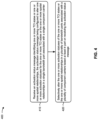
- Fig. 4 is a diagram illustrating an example process 400 performed, for example, by a UE, in accordance with various aspects of the present disclosure.
- Example process 400 is an example where the UE (e.g., UE 120 and/or the like) performs operations associated with TCI state activation and deactivation.
- the UE e.g., UE 120 and/or the like
- process 400 may include receiving an activation status message identifying one or more TCI states or one or more spatial relationships, the activation status message being configured to alter one or more activation statuses for the one or more TCI states or the one or more spatial relationships in a single bandwidth part associated with a single component carrier (block 410).
- the UE e.g., using antenna 252, DEMOD 254, MIMO detector 256, receive processor 258, controller/processor 280, and/or the like
- receiving the activation status message includes transmitting a UE capability indicator to indicate that the UE is capable of applying the activation status message to the plurality of bandwidth parts, and receiving the activation status message based at least in part on transmitting the UE capability indicator.
- the plurality of bandwidth parts and the plurality of component carriers are in a same band.
- the activation status message is a medium access control control element.
- the activation status indicator is a bit indicator of a radio resource configuration message control message.
- the activation status indicator is a bit indicator of a downlink control information of a downlink shared channel medium access control control element.
- the one or more TCI states are associated with semi-persistent channel state information reference signal resources or channel state information interference measurement resources.
- the one or more spatial relationships are associated with semi-persistent sounding reference signal resources.
- the one or more TCI states are associated with physical downlink control channel resources.
- the one or more TCI states are associated with physical downlink shared channel resources.
- process 400 may include selectively altering the one or more activation statuses of the one or more TCI states or the one or more spatial relationships in a plurality of bandwidth parts associated with a plurality of component carriers based at least in part on receiving the activation status message (block 420).
- the UE may selectively alter the one or more activation statuses of the one or more TCI states or the one or more spatial relationships in a plurality of bandwidth parts associated with a plurality of component carriers based at least in part on receiving the activation status message, as described above in connection with Figs. 3A-3D .
- the activation status message is an activation message, and selectively altering the one or more activation statuses of the one or more TCI states or the one or more spatial relationships includes activating the one or more TCI states or the one or more spatial relationships.
- the activation status message is a deactivation message
- selectively altering the one or more activation statuses of the one or more TCI states includes deactivating the one or more TCI states or the one or more spatial relationships.
- selectively altering the one or more activation statuses includes altering the one or more spatial relationships in the plurality of bandwidth parts.
- process 400 includes receiving the activation status indicator indicating that the activation status message is to apply to more than one bandwidth part, and selectively altering the one or more activation statuses of the one or more TCI states or the one or more spatial relationships in the plurality of bandwidth parts associated with the plurality of component carriers includes altering the one or more activation statuses of the one or more TCI states or the one or more spatial relationships in the plurality of bandwidth parts associated with the plurality of component carriers based at least in part on the activation status indicator.
- process 400 may include additional blocks, fewer blocks, different blocks, or differently arranged blocks than those depicted in Fig. 4 . Additionally, or alternatively, two or more of the blocks of process 400 may be performed in parallel.
- Fig. 5 is a conceptual data flow diagram illustrating an example 500 of a data flow between different modules/means/components in an example apparatus 502.
- the apparatus 502 may include, for example, a UE (e.g., UE 120).
- the apparatus 502 includes a reception module 504, an alteration module 506, and a transmission module 508.
- transmission module 508 may transmit information to, for example, a BS.
- transmission module 508 provides a UE capability indicator indicating that the apparatus 502 is capable of applying a single activation status message for a single bandwidth part to a plurality of bandwidth parts, as described with regard to Figs. 3A-3D .
- Fig. 6 is a diagram illustrating an example 600 of a hardware implementation for an apparatus 502' (e.g., apparatus 502 described above in connection with Fig. 5 ) employing a processing system 602.
- the apparatus 502' may include, for example, a UE (e.g., UE 120).
- the processing system 602 may be implemented with a bus architecture, represented generally by the bus 604.
- the bus 604 may include any number of interconnecting buses and bridges depending on the specific application of the processing system 602 and the overall design constraints.
- the bus 604 links together various circuits including one or more processors and/or hardware modules, represented by the processor 606, the modules 504, 506, and/or 508, and the computer-readable medium / memory 608.
- the bus 604 may also link various other circuits such as timing sources, peripherals, voltage regulators, and power management circuits, which are well known in the art, and therefore, will not be described any further.
- the processing system 602 may be coupled to a transceiver 610.
- the transceiver 610 is coupled to one or more antennas 612.
- the transceiver 610 provides a means for communicating with various other apparatuses over a transmission medium.
- the transceiver 610 receives a signal from the one or more antennas 612, extracts information from the received signal, and provides the extracted information to the processing system 602.
- the transceiver 610 receives information from the processing system 602 and, based at least in part on the received information, generates a signal to be applied to the one or more antennas 612.
- the processing system 602 includes a processor 606 coupled to a computer-readable medium / memory 608.
- the processor 606 is responsible for general processing, including the execution of software stored on the computer-readable medium / memory 608.
- the software when executed by the processor 606, causes the processing system 602 to perform the various functions described herein for any particular apparatus.
- the computer-readable medium / memory 608 may also be used for storing data that is manipulated by the processor 606 when executing software.
- the processing system further includes at least one of the modules 504, 506, and/or 508.
- the modules may be software modules running in the processor 606, resident/stored in the computer readable medium / memory 608, one or more hardware modules coupled to the processor 606, or some combination thereof.
- the apparatus 502 for wireless communication includes means for receiving an activation status message identifying one or more TCI states or one or more spatial relationships, the activation status message being configured to alter one or more activation statuses for the one or more TCI states or the one or more spatial relationships in a single bandwidth part associated with a single component carrier, means for selectively altering the one or more activation statuses of the one or more TCI states or the one or more spatial relationships in a plurality of bandwidth parts associated with a plurality of component carriers based at least in part on receiving the activation status message, and/or the like.
- the aforementioned means may be one or more of the aforementioned modules of the apparatus 502 and/or the processing system 602 of the apparatus 502' configured to perform the functions recited by the aforementioned means.
- Fig. 6 is provided as an example. Other examples may differ from what is described with regard to Fig. 6 .
- ком ⁇ онент is intended to be broadly construed as hardware, firmware, and/or a combination of hardware and software.
- a processor is implemented in hardware, firmware, and/or a combination of hardware and software.
- satisfying a threshold may, depending on the context, refer to a value being greater than the threshold, greater than or equal to the threshold, less than the threshold, less than or equal to the threshold, equal to the threshold, not equal to the threshold, and/or the like.
- "at least one of: a, b, or c” is intended to cover a, b, c, a-b, a-c, b-c, and a-b-c, as well as any combination with multiples of the same element (e.g., a-a, a-a-a, a-a-b, a-a-c, a-b-b, a-c-c, b-b, b-b-b, b-b-c, c-c, and c-c-c or any other ordering of a, b, and c).
Landscapes
- Engineering & Computer Science (AREA)
- Signal Processing (AREA)
- Computer Networks & Wireless Communication (AREA)
- Mobile Radio Communication Systems (AREA)
Claims (14)
- Un procédé de communication sans fil réalisé par un équipement utilisateur, UE (120), comprenant :la transmission d'un indicateur de capacité d'UE pour indiquer que l'UE (120) est capable d'appliquer un message de statut d'activation (320-A, 320-B, 320-C, 320-D) à une pluralité de parties de largeur de bande ;la réception (310, 410) du message de statut d'activation (320-A, 320-B, 320-C, 320-D) identifiant un ou plusieurs états d'indicateur de configuration de transmission, TCI, ou une ou plusieurs relations spatiales, le message de statut d'activation (320-A, 320-B, 320-C, 320-D) étant configuré pour modifier un ou plusieurs statuts d'activation pour les un ou plusieurs états de TCI ou les une ou plusieurs relations spatiales dans une seule partie de largeur de bande associée à une unique porteuse composante, dans lequel la réception (310, 410) du message de statut d'activation (320-A, 320-B, 320-C, 320-D) comprend :
la réception du message de statut d'activation (320-A, 320-B, 320-C, 320-D) sur la base au moins en partie de la transmission de l'indicateur de capacité d'UE ; et la modification (330, 420) des un ou plusieurs statuts d'activation des un ou plusieurs états de TCI ou des une ou plusieurs relations spatiales dans la pluralité de parties de largeur de bande associées à une pluralité de porteuses composantes sur la base au moins en partie d'un indicateur de statut d'activation indiquant si le message de statut d'activation (320-A, 320-B, 320-C, 320-D) doit s'appliquer à plus qu'une partie de largeur de bande de la pluralité de parties de largeur de bande. - Le procédé selon la revendication 1, dans lequel le message de statut d'activation (320-A, 320-B, 320-C, 320-D) est un message d'activation, et
dans lequel la modification (330, 420) des un ou plusieurs statuts d'activation des un ou plusieurs états de TCI ou des une ou plusieurs relations spatiales comprend : l'activation des un ou plusieurs états de TCI ou des une ou plusieurs relations spatiales. - Le procédé selon la revendication 1, dans lequel le message de statut d'activation (320-A, 320-B, 320-C, 320-D) est un message de désactivation, et
dans lequel la modification (330, 420) des un ou plusieurs statuts d'activation des un ou plusieurs états de TCI comprend :
la désactivation d'un ou plusieurs états de TCI ou d'une ou plusieurs relations spatiales. - Le procédé selon la revendication 1, dans lequel la modification (330, 420) des un ou plusieurs statuts d'activation comprend :
la modification des une ou plusieurs relations spatiales dans la pluralité de parties de largeur de bande. - Le procédé selon la revendication 1, dans lequel la pluralité de parties de largeur de bande et la pluralité de porteuses composantes sont dans une même bande.
- Le procédé selon la revendication 1, dans lequel le message de statut d'activation (320-A, 320-B, 320-C, 320-D) est un élément de contrôle de contrôle d'accès au support, MAC-CE.
- Le procédé selon la revendication 1, comprenant en outre :
la réception de l'indicateur de statut d'activation indiquant que le message de statut d'activation (320-A, 320-B, 320-C, 320-D) doit s'appliquer à plus qu'une partie de largeur de bande. - Le procédé selon la revendication 1, dans lequel l'indicateur de statut d'activation est un indicateur de bit d'un message de contrôle de message de configuration de ressource radio, RRC.
- Le procédé selon la revendication 1, dans lequel les un ou plusieurs états de TCI sont associés à des ressources semi-persistantes de signal de référence d'information d'état de canal ou à des ressources de mesure d'interférence d'information d'état de canal.
- Le procédé selon la revendication 1, dans lequel les une ou plusieurs relations spatiales sont associées à des ressources semi-persistantes de signal de référence de sondage.
- Le procédé selon la revendication 1, dans lequel les un ou plusieurs états de TCI sont associés à des ressources de canal physique de contrôle de liaison descendante.
- Le procédé selon la revendication 1, dans lequel les un ou plusieurs états de TCI sont associés à des ressources de canal physique partagé de liaison descendante.
- Un support lisible par calculateur stockant une ou plusieurs instructions de communication sans fil, les une ou plusieurs instructions comprenant un code de programme amenant un calculateur d'un équipement utilisateur, UE (120), à réaliser un procédé selon l'une des revendications 1 à 12, lorsqu'il est exécuté.
- Un appareil pour la communication sans fil au niveau d'un équipement utilisateur, UE (120), comprenant :un moyen pour transmettre un indicateur de capacité d'UE pour indiquer que l'UE (120) est capable d'appliquer un message de statut d'activation (320-A, 320-B, 320-C, 320-D) à une pluralité de parties de largeur de bande ;un moyen pour recevoir le message de statut d'activation (320-A, 320-B, 320-C, 320-D) identifiant un ou plusieurs d'états d'indicateur de configuration de transmission, TCI, ou une ou plusieurs relations spatiales, le message de statut d'activation (320-A, 320-B, 320-C, 320-D) étant configuré pour modifier un ou plusieurs statuts d'activation pour les un ou plusieurs états de TCI ou les une ou plusieurs relations spatiales dans une seule partie de largeur de bande associée à une unique porteuse composante, dans lequel la réception du message de statut d'activation (320-A, 320-B, 320-C, 320-D) comprend :
la réception du message de statut d'activation (320-A, 320-B, 320-C, 320-D) sur la base au moins en partie de la transmission de l'indicateur de capacité d'UE ; et un moyen pour la modification des un ou plusieurs statuts d'activation des un ou plusieurs états de TCI ou des une ou plusieurs relations spatiales dans la pluralité de parties de largeur de bande associées à une pluralité de porteuses composantes sur la base au moins en partie d'un indicateur de statut d'activation indiquant si le message de statut d'activation (320-A, 320-B, 320-C, 320-D) doit s'appliquer à plus qu'une partie de largeur de bande de la pluralité de parties de largeur de bande.
Applications Claiming Priority (3)
| Application Number | Priority Date | Filing Date | Title |
|---|---|---|---|
| US201962894274P | 2019-08-30 | 2019-08-30 | |
| US16/947,988 US11563550B2 (en) | 2019-08-30 | 2020-08-26 | Transmission configuration indicator state activation and deactivation |
| PCT/US2020/070467 WO2021042125A1 (fr) | 2019-08-30 | 2020-08-27 | Activation et désactivation d'état d'indicateur de configuration de transmission |
Publications (2)
| Publication Number | Publication Date |
|---|---|
| EP4022826A1 EP4022826A1 (fr) | 2022-07-06 |
| EP4022826B1 true EP4022826B1 (fr) | 2025-04-16 |
Family
ID=74681912
Family Applications (1)
| Application Number | Title | Priority Date | Filing Date |
|---|---|---|---|
| EP20768488.7A Active EP4022826B1 (fr) | 2019-08-30 | 2020-08-27 | Activation et deactivation d'etat de l'indicator de configuration de transmission |
Country Status (4)
| Country | Link |
|---|---|
| US (1) | US11563550B2 (fr) |
| EP (1) | EP4022826B1 (fr) |
| CN (1) | CN114271001B (fr) |
| WO (1) | WO2021042125A1 (fr) |
Families Citing this family (2)
| Publication number | Priority date | Publication date | Assignee | Title |
|---|---|---|---|---|
| CN116368935B (zh) * | 2020-10-22 | 2025-11-11 | 苹果公司 | 用于波束故障检测的装置、方法和存储介质 |
| WO2023201622A1 (fr) * | 2022-04-21 | 2023-10-26 | Apple Inc. | Mise a jour de l'indicateur de configuration de transmission et commutation partielle de la bande passante pour les porteuses composantes multiples |
Family Cites Families (10)
| Publication number | Priority date | Publication date | Assignee | Title |
|---|---|---|---|---|
| ES2410680B1 (es) * | 2011-08-22 | 2014-07-30 | Telefónica, S.A. | Método para facilitar la minimización de interferencia intercelular aprovechando sus características conocidas |
| US10959218B2 (en) * | 2016-11-14 | 2021-03-23 | Comcast Cable Communications, Llc | Semi-persistent scheduling confirmation |
| CN109391935B (zh) * | 2017-08-11 | 2021-01-08 | 维沃移动通信有限公司 | 一种带宽部分的配置方法、网络设备及终端 |
| US10707923B2 (en) * | 2017-10-13 | 2020-07-07 | Qualcomm Incorporated | Dynamic transmission configuration indication state updating |
| CN109802787B (zh) * | 2017-11-17 | 2021-01-08 | 维沃移动通信有限公司 | 传输配置指示tci的传输方法、网络侧设备和终端设备 |
| US10893431B2 (en) * | 2018-01-19 | 2021-01-12 | Asustek Computer Inc. | Method and apparatus for beam failure reporting under multicell configuration in a wireless communication system |
| US11297674B2 (en) | 2018-02-14 | 2022-04-05 | Samsung Electronics Co., Ltd. | Method and apparatus for power savings at a user equipment |
| CN112673581B (zh) * | 2018-07-12 | 2024-02-13 | 株式会社Ntt都科摩 | 用户终端 |
| US10980035B2 (en) * | 2018-12-03 | 2021-04-13 | Apple Inc. | Supplemental use of millimeter wave spectrum |
| US11929805B2 (en) * | 2019-07-26 | 2024-03-12 | Ofinno, Llc | Channel state information reporting for non-coherent joint transmission |
-
2020
- 2020-08-26 US US16/947,988 patent/US11563550B2/en active Active
- 2020-08-27 EP EP20768488.7A patent/EP4022826B1/fr active Active
- 2020-08-27 CN CN202080059609.XA patent/CN114271001B/zh active Active
- 2020-08-27 WO PCT/US2020/070467 patent/WO2021042125A1/fr not_active Ceased
Non-Patent Citations (1)
| Title |
|---|
| NOKIA ET AL: "Remaining Issues on Beam Management", vol. RAN WG1, no. Busan, Korea; 20180421 - 20180425, 20 May 2018 (2018-05-20), XP051442381, Retrieved from the Internet <URL:http://www.3gpp.org/ftp/Meetings%5F3GPP%5FSYNC/RAN1/Docs/> [retrieved on 20180520] * |
Also Published As
| Publication number | Publication date |
|---|---|
| US11563550B2 (en) | 2023-01-24 |
| WO2021042125A1 (fr) | 2021-03-04 |
| US20210067306A1 (en) | 2021-03-04 |
| CN114271001A (zh) | 2022-04-01 |
| CN114271001B (zh) | 2025-02-18 |
| EP4022826A1 (fr) | 2022-07-06 |
Similar Documents
| Publication | Publication Date | Title |
|---|---|---|
| US12323953B2 (en) | Configuration of resource patterns for integrated access and backhaul | |
| WO2021155502A1 (fr) | Multiplexage d'uci sur un pusch permettant une transmission en liaison montante à panneaux multiples | |
| US11277830B2 (en) | Configuration of soft time resources for an IAB node with multiple parent nodes | |
| US12550123B2 (en) | Uplink transmission configuration indication state signaling | |
| US11864215B2 (en) | Beam determination prior to beam activation indication | |
| KR102935456B1 (ko) | 자원-특정 송신 전력 제어 구성을 위한 기법들 | |
| WO2021127673A1 (fr) | Techniques d'activation d'un signal de référence d'affaiblissement le long du trajet | |
| KR20220133891A (ko) | 다수의 컴포넌트 캐리어들에 걸친 동시적 빔 업데이트를 위한 사용자 장비 능력을 표시하기 위한 기법들 | |
| US11424800B2 (en) | Techniques for scheduling a front-loaded sidelink channel state information reference signal | |
| WO2021154450A1 (fr) | Techniques d'indication de faisceaux pour un rapport de faisceau d'équipement utilisateur | |
| WO2021155566A1 (fr) | Indication de capacité d'équipement utilisateur pour un état d'indication de configuration de transmission de liaison montante et des informations de relation spatiale | |
| WO2021011107A1 (fr) | Sélection autonome d'un faisceau de canal physique de commande de liaison descendante | |
| EP3925314A1 (fr) | État de surveillance réduite | |
| WO2021114127A1 (fr) | Configuration de quasi-colocalisation | |
| WO2021120083A1 (fr) | Indication de faisceau pour transmission par liaison latérale programmée d'informations de commande de liaison descendante | |
| EP4022826B1 (fr) | Activation et deactivation d'etat de l'indicator de configuration de transmission | |
| US11641649B2 (en) | Transmission of a beam failure recovery request via a secondary cell used for carrier aggregation | |
| WO2021232390A1 (fr) | Configuration d'informations de commande de liaison descendante de signaux de référence de sondage communs d'un groupe | |
| WO2021068228A1 (fr) | Configuration de signal de référence de démodulation pour de multiples configurations de canal physique partagé de liaison montante d'autorisation configurée | |
| WO2021223212A1 (fr) | Mise à jour de signal de référence d'affaiblissement de trajet pour de multiples ressources | |
| WO2021179193A1 (fr) | Accès basé sur un conflit et permettant une transmission en liaison montante avec agrégation de porteuses |
Legal Events
| Date | Code | Title | Description |
|---|---|---|---|
| STAA | Information on the status of an ep patent application or granted ep patent |
Free format text: STATUS: UNKNOWN |
|
| STAA | Information on the status of an ep patent application or granted ep patent |
Free format text: STATUS: THE INTERNATIONAL PUBLICATION HAS BEEN MADE |
|
| PUAI | Public reference made under article 153(3) epc to a published international application that has entered the european phase |
Free format text: ORIGINAL CODE: 0009012 |
|
| STAA | Information on the status of an ep patent application or granted ep patent |
Free format text: STATUS: REQUEST FOR EXAMINATION WAS MADE |
|
| 17P | Request for examination filed |
Effective date: 20220119 |
|
| AK | Designated contracting states |
Kind code of ref document: A1 Designated state(s): AL AT BE BG CH CY CZ DE DK EE ES FI FR GB GR HR HU IE IS IT LI LT LU LV MC MK MT NL NO PL PT RO RS SE SI SK SM TR |
|
| DAV | Request for validation of the european patent (deleted) | ||
| DAX | Request for extension of the european patent (deleted) | ||
| STAA | Information on the status of an ep patent application or granted ep patent |
Free format text: STATUS: EXAMINATION IS IN PROGRESS |
|
| 17Q | First examination report despatched |
Effective date: 20230508 |
|
| GRAP | Despatch of communication of intention to grant a patent |
Free format text: ORIGINAL CODE: EPIDOSNIGR1 |
|
| STAA | Information on the status of an ep patent application or granted ep patent |
Free format text: STATUS: GRANT OF PATENT IS INTENDED |
|
| INTG | Intention to grant announced |
Effective date: 20241209 |
|
| GRAS | Grant fee paid |
Free format text: ORIGINAL CODE: EPIDOSNIGR3 |
|
| GRAA | (expected) grant |
Free format text: ORIGINAL CODE: 0009210 |
|
| STAA | Information on the status of an ep patent application or granted ep patent |
Free format text: STATUS: THE PATENT HAS BEEN GRANTED |
|
| AK | Designated contracting states |
Kind code of ref document: B1 Designated state(s): AL AT BE BG CH CY CZ DE DK EE ES FI FR GB GR HR HU IE IS IT LI LT LU LV MC MK MT NL NO PL PT RO RS SE SI SK SM TR |
|
| REG | Reference to a national code |
Ref country code: GB Ref legal event code: FG4D |
|
| REG | Reference to a national code |
Ref country code: CH Ref legal event code: EP |
|
| REG | Reference to a national code |
Ref country code: IE Ref legal event code: FG4D |
|
| REG | Reference to a national code |
Ref country code: DE Ref legal event code: R096 Ref document number: 602020049584 Country of ref document: DE |
|
| REG | Reference to a national code |
Ref country code: NL Ref legal event code: MP Effective date: 20250416 |
|
| PG25 | Lapsed in a contracting state [announced via postgrant information from national office to epo] |
Ref country code: NL Free format text: LAPSE BECAUSE OF FAILURE TO SUBMIT A TRANSLATION OF THE DESCRIPTION OR TO PAY THE FEE WITHIN THE PRESCRIBED TIME-LIMIT Effective date: 20250416 |
|
| REG | Reference to a national code |
Ref country code: AT Ref legal event code: MK05 Ref document number: 1786570 Country of ref document: AT Kind code of ref document: T Effective date: 20250416 |
|
| PG25 | Lapsed in a contracting state [announced via postgrant information from national office to epo] |
Ref country code: FI Free format text: LAPSE BECAUSE OF FAILURE TO SUBMIT A TRANSLATION OF THE DESCRIPTION OR TO PAY THE FEE WITHIN THE PRESCRIBED TIME-LIMIT Effective date: 20250416 Ref country code: PT Free format text: LAPSE BECAUSE OF FAILURE TO SUBMIT A TRANSLATION OF THE DESCRIPTION OR TO PAY THE FEE WITHIN THE PRESCRIBED TIME-LIMIT Effective date: 20250818 Ref country code: ES Free format text: LAPSE BECAUSE OF FAILURE TO SUBMIT A TRANSLATION OF THE DESCRIPTION OR TO PAY THE FEE WITHIN THE PRESCRIBED TIME-LIMIT Effective date: 20250416 |
|
| PGFP | Annual fee paid to national office [announced via postgrant information from national office to epo] |
Ref country code: DE Payment date: 20250709 Year of fee payment: 6 |
|
| REG | Reference to a national code |
Ref country code: LT Ref legal event code: MG9D |
|
| PG25 | Lapsed in a contracting state [announced via postgrant information from national office to epo] |
Ref country code: GR Free format text: LAPSE BECAUSE OF FAILURE TO SUBMIT A TRANSLATION OF THE DESCRIPTION OR TO PAY THE FEE WITHIN THE PRESCRIBED TIME-LIMIT Effective date: 20250717 Ref country code: NO Free format text: LAPSE BECAUSE OF FAILURE TO SUBMIT A TRANSLATION OF THE DESCRIPTION OR TO PAY THE FEE WITHIN THE PRESCRIBED TIME-LIMIT Effective date: 20250716 |
|
| PG25 | Lapsed in a contracting state [announced via postgrant information from national office to epo] |
Ref country code: PL Free format text: LAPSE BECAUSE OF FAILURE TO SUBMIT A TRANSLATION OF THE DESCRIPTION OR TO PAY THE FEE WITHIN THE PRESCRIBED TIME-LIMIT Effective date: 20250416 |
|
| PG25 | Lapsed in a contracting state [announced via postgrant information from national office to epo] |
Ref country code: BG Free format text: LAPSE BECAUSE OF FAILURE TO SUBMIT A TRANSLATION OF THE DESCRIPTION OR TO PAY THE FEE WITHIN THE PRESCRIBED TIME-LIMIT Effective date: 20250416 |
|
| PGFP | Annual fee paid to national office [announced via postgrant information from national office to epo] |
Ref country code: GB Payment date: 20250710 Year of fee payment: 6 |
|
| PG25 | Lapsed in a contracting state [announced via postgrant information from national office to epo] |
Ref country code: HR Free format text: LAPSE BECAUSE OF FAILURE TO SUBMIT A TRANSLATION OF THE DESCRIPTION OR TO PAY THE FEE WITHIN THE PRESCRIBED TIME-LIMIT Effective date: 20250416 |
|
| PG25 | Lapsed in a contracting state [announced via postgrant information from national office to epo] |
Ref country code: AT Free format text: LAPSE BECAUSE OF FAILURE TO SUBMIT A TRANSLATION OF THE DESCRIPTION OR TO PAY THE FEE WITHIN THE PRESCRIBED TIME-LIMIT Effective date: 20250416 |
|
| PGFP | Annual fee paid to national office [announced via postgrant information from national office to epo] |
Ref country code: FR Payment date: 20250709 Year of fee payment: 6 |
|
| PG25 | Lapsed in a contracting state [announced via postgrant information from national office to epo] |
Ref country code: RS Free format text: LAPSE BECAUSE OF FAILURE TO SUBMIT A TRANSLATION OF THE DESCRIPTION OR TO PAY THE FEE WITHIN THE PRESCRIBED TIME-LIMIT Effective date: 20250716 |
|
| PG25 | Lapsed in a contracting state [announced via postgrant information from national office to epo] |
Ref country code: IS Free format text: LAPSE BECAUSE OF FAILURE TO SUBMIT A TRANSLATION OF THE DESCRIPTION OR TO PAY THE FEE WITHIN THE PRESCRIBED TIME-LIMIT Effective date: 20250816 |
|
| PG25 | Lapsed in a contracting state [announced via postgrant information from national office to epo] |
Ref country code: LV Free format text: LAPSE BECAUSE OF FAILURE TO SUBMIT A TRANSLATION OF THE DESCRIPTION OR TO PAY THE FEE WITHIN THE PRESCRIBED TIME-LIMIT Effective date: 20250416 |
|
| PG25 | Lapsed in a contracting state [announced via postgrant information from national office to epo] |
Ref country code: SM Free format text: LAPSE BECAUSE OF FAILURE TO SUBMIT A TRANSLATION OF THE DESCRIPTION OR TO PAY THE FEE WITHIN THE PRESCRIBED TIME-LIMIT Effective date: 20250416 Ref country code: DK Free format text: LAPSE BECAUSE OF FAILURE TO SUBMIT A TRANSLATION OF THE DESCRIPTION OR TO PAY THE FEE WITHIN THE PRESCRIBED TIME-LIMIT Effective date: 20250416 |
|
| REG | Reference to a national code |
Ref country code: DE Ref legal event code: R097 Ref document number: 602020049584 Country of ref document: DE |
|
| PG25 | Lapsed in a contracting state [announced via postgrant information from national office to epo] |
Ref country code: CZ Free format text: LAPSE BECAUSE OF FAILURE TO SUBMIT A TRANSLATION OF THE DESCRIPTION OR TO PAY THE FEE WITHIN THE PRESCRIBED TIME-LIMIT Effective date: 20250416 |
|
| PG25 | Lapsed in a contracting state [announced via postgrant information from national office to epo] |
Ref country code: EE Free format text: LAPSE BECAUSE OF FAILURE TO SUBMIT A TRANSLATION OF THE DESCRIPTION OR TO PAY THE FEE WITHIN THE PRESCRIBED TIME-LIMIT Effective date: 20250416 |
|
| PG25 | Lapsed in a contracting state [announced via postgrant information from national office to epo] |
Ref country code: SK Free format text: LAPSE BECAUSE OF FAILURE TO SUBMIT A TRANSLATION OF THE DESCRIPTION OR TO PAY THE FEE WITHIN THE PRESCRIBED TIME-LIMIT Effective date: 20250416 Ref country code: RO Free format text: LAPSE BECAUSE OF FAILURE TO SUBMIT A TRANSLATION OF THE DESCRIPTION OR TO PAY THE FEE WITHIN THE PRESCRIBED TIME-LIMIT Effective date: 20250416 |
|
| PG25 | Lapsed in a contracting state [announced via postgrant information from national office to epo] |
Ref country code: IT Free format text: LAPSE BECAUSE OF FAILURE TO SUBMIT A TRANSLATION OF THE DESCRIPTION OR TO PAY THE FEE WITHIN THE PRESCRIBED TIME-LIMIT Effective date: 20250416 |
|
| PLBE | No opposition filed within time limit |
Free format text: ORIGINAL CODE: 0009261 |
|
| STAA | Information on the status of an ep patent application or granted ep patent |
Free format text: STATUS: NO OPPOSITION FILED WITHIN TIME LIMIT |
|
| REG | Reference to a national code |
Ref country code: CH Ref legal event code: L10 Free format text: ST27 STATUS EVENT CODE: U-0-0-L10-L00 (AS PROVIDED BY THE NATIONAL OFFICE) Effective date: 20260225 |
|
| REG | Reference to a national code |
Ref country code: CH Ref legal event code: H13 Free format text: ST27 STATUS EVENT CODE: U-0-0-H10-H13 (AS PROVIDED BY THE NATIONAL OFFICE) Effective date: 20260324 |
|
| 26N | No opposition filed |
Effective date: 20260119 |
|
| PG25 | Lapsed in a contracting state [announced via postgrant information from national office to epo] |
Ref country code: MC Free format text: LAPSE BECAUSE OF FAILURE TO SUBMIT A TRANSLATION OF THE DESCRIPTION OR TO PAY THE FEE WITHIN THE PRESCRIBED TIME-LIMIT Effective date: 20250416 |
|
| PG25 | Lapsed in a contracting state [announced via postgrant information from national office to epo] |
Ref country code: LU Free format text: LAPSE BECAUSE OF NON-PAYMENT OF DUE FEES Effective date: 20250827 |
|
| PG25 | Lapsed in a contracting state [announced via postgrant information from national office to epo] |
Ref country code: CH Free format text: LAPSE BECAUSE OF NON-PAYMENT OF DUE FEES Effective date: 20250831 |