EP4022929B1 - Codeur, décodeur avec prise en charge des fréquences d'image de sous-couche - Google Patents
Codeur, décodeur avec prise en charge des fréquences d'image de sous-couche Download PDFInfo
- Publication number
- EP4022929B1 EP4022929B1 EP20869593.2A EP20869593A EP4022929B1 EP 4022929 B1 EP4022929 B1 EP 4022929B1 EP 20869593 A EP20869593 A EP 20869593A EP 4022929 B1 EP4022929 B1 EP 4022929B1
- Authority
- EP
- European Patent Office
- Prior art keywords
- flag
- temporal
- sub
- picture
- value
- Prior art date
- Legal status (The legal status is an assumption and is not a legal conclusion. Google has not performed a legal analysis and makes no representation as to the accuracy of the status listed.)
- Active
Links
Images


Classifications
-
- H—ELECTRICITY
- H04—ELECTRIC COMMUNICATION TECHNIQUE
- H04N—PICTORIAL COMMUNICATION, e.g. TELEVISION
- H04N19/00—Methods or arrangements for coding, decoding, compressing or decompressing digital video signals
- H04N19/46—Embedding additional information in the video signal during the compression process
-
- H—ELECTRICITY
- H04—ELECTRIC COMMUNICATION TECHNIQUE
- H04N—PICTORIAL COMMUNICATION, e.g. TELEVISION
- H04N19/00—Methods or arrangements for coding, decoding, compressing or decompressing digital video signals
- H04N19/10—Methods or arrangements for coding, decoding, compressing or decompressing digital video signals using adaptive coding
- H04N19/134—Methods or arrangements for coding, decoding, compressing or decompressing digital video signals using adaptive coding characterised by the element, parameter or criterion affecting or controlling the adaptive coding
- H04N19/146—Data rate or code amount at the encoder output
-
- H—ELECTRICITY
- H04—ELECTRIC COMMUNICATION TECHNIQUE
- H04N—PICTORIAL COMMUNICATION, e.g. TELEVISION
- H04N19/00—Methods or arrangements for coding, decoding, compressing or decompressing digital video signals
- H04N19/10—Methods or arrangements for coding, decoding, compressing or decompressing digital video signals using adaptive coding
- H04N19/169—Methods or arrangements for coding, decoding, compressing or decompressing digital video signals using adaptive coding characterised by the coding unit, i.e. the structural portion or semantic portion of the video signal being the object or the subject of the adaptive coding
- H04N19/17—Methods or arrangements for coding, decoding, compressing or decompressing digital video signals using adaptive coding characterised by the coding unit, i.e. the structural portion or semantic portion of the video signal being the object or the subject of the adaptive coding the unit being an image region, e.g. an object
- H04N19/172—Methods or arrangements for coding, decoding, compressing or decompressing digital video signals using adaptive coding characterised by the coding unit, i.e. the structural portion or semantic portion of the video signal being the object or the subject of the adaptive coding the unit being an image region, e.g. an object the region being a picture, frame or field
-
- H—ELECTRICITY
- H04—ELECTRIC COMMUNICATION TECHNIQUE
- H04N—PICTORIAL COMMUNICATION, e.g. TELEVISION
- H04N19/00—Methods or arrangements for coding, decoding, compressing or decompressing digital video signals
- H04N19/30—Methods or arrangements for coding, decoding, compressing or decompressing digital video signals using hierarchical techniques, e.g. scalability
- H04N19/31—Methods or arrangements for coding, decoding, compressing or decompressing digital video signals using hierarchical techniques, e.g. scalability in the temporal domain
-
- H—ELECTRICITY
- H04—ELECTRIC COMMUNICATION TECHNIQUE
- H04N—PICTORIAL COMMUNICATION, e.g. TELEVISION
- H04N19/00—Methods or arrangements for coding, decoding, compressing or decompressing digital video signals
- H04N19/70—Methods or arrangements for coding, decoding, compressing or decompressing digital video signals characterised by syntax aspects related to video coding, e.g. related to compression standards
-
- H—ELECTRICITY
- H04—ELECTRIC COMMUNICATION TECHNIQUE
- H04N—PICTORIAL COMMUNICATION, e.g. TELEVISION
- H04N21/00—Selective content distribution, e.g. interactive television or video on demand [VOD]
- H04N21/80—Generation or processing of content or additional data by content creator independently of the distribution process; Content per se
- H04N21/85—Assembly of content; Generation of multimedia applications
- H04N21/854—Content authoring
- H04N21/85406—Content authoring involving a specific file format, e.g. MP4 format
Definitions
- Embodiments of the present application generally relate to signalling and coding of mapping sub-layers to picture rates in video coding by Supplemental Enhancement Information (SEI) in the Advanced Video Coding (AVC), High Efficiency Video Coding (HEVC), Versatile Video Coding (VVC) and other video coding standards. More specifically, this disclosure describes the signaling of the table that allows mapping of Temporal IDs (TID) of sub-layers with corresponding picture rates.
- SEI Supplemental Enhancement Information
- AVC Advanced Video Coding
- HEVC High Efficiency Video Coding
- VVC Versatile Video Coding
- this disclosure describes the signaling of the table that allows mapping of Temporal IDs (TID) of sub-layers with corresponding picture rates.
- TID Temporal IDs
- the description of the techniques is based on the under-development video coding standard Versatile Video Coding (VVC) by the joint video experts team (JVET) of ITU-T and ISO/IEC. However, the techniques also apply to other video codec specifications.
- Video compression techniques perform spatial (intra-picture) prediction and/or temporal (inter-picture) prediction to reduce or remove redundancy inherent in video sequences.
- a video slice i.e., a video picture or a portion of a video picture
- video blocks which may also be referred to as treeblocks, coding tree blocks (CTBs), coding tree units (CTUs), coding units (CUs) and/or coding nodes.
- Video blocks in an intra-coded (I) slice of a picture are encoded using spatial prediction with respect to reference samples in neighboring blocks in the same picture.
- Video blocks in an inter-coded (P or B) slice of a picture may use spatial prediction with respect to reference samples in neighboring blocks in the same picture or temporal prediction with respect to reference samples in other reference pictures.
- Pictures may be referred to as frames, and reference pictures may be referred to as reference frames.
- Residual data represents pixel differences between the original block to be coded and the predictive block.
- An inter-coded block is encoded according to a motion vector that points to a block of reference samples forming the predictive block, and the residual data indicating the difference between the coded block and the predictive block.
- An intra-coded block is encoded according to an intra-coding mode and the residual data.
- the residual data may be transformed from the pixel domain to a transform domain, resulting in residual transform coefficients, which then may be quantized.
- the quantized transform coefficients initially arranged in a two-dimensional array, may be scanned in order to produce a one-dimensional vector of transform coefficients, and entropy coding may be applied to achieve even more compression.
- ITU-T H.261 ISO/IEC MPEG-1 Part 2, ITU-T H.262 or ISO/IEC MPEG-2 Part 2
- AVC Advanced Video Coding
- HEVC High Efficiency Video Coding
- SVC Scalable Video Coding
- MVC Multiview Video Coding
- MVC+D Multiview Video Coding plus Depth
- 3D-AVC 3D-AVC
- VVC Versatile Video Coding
- JVET joint video experts team
- WD Working Draft
- Embodiments of the present application provide apparatuses and methods for encoding and decoding according to the independent claims.
- a method of coding implemented by a decoding/encoding device for coding video data comprising:
- the new SEI message provides to an external application or network the list of picture rates associated with the list of Temporal IDs.
- coding the set of sequence parameters associated with the temporal IDs in the SEI message may comprise coding an indication indicating a special payload type for the SEI message.
- the sequence may comprise one or more sub-sequences, wherein the set of sequence parameters may be used for deriving or representing a picture rate of the one or more of the sub-sequences.
- the temporal IDs may be associated with a subset of general layer IDs, wherein at least one of the general layer IDs may be a temporal layer ID, or a Signal to Noise Ratio, SNR, layer ID, or a spatial layer ID.
- the set of sequence parameters may include one or more of following parameters: a highest temporal ID, TID, time scale value indicating the number of time units that pass in one second, a flag of dyadic temporal ID distribution indicating a fixed picture rate and a dyadic hierarchical distribution for all sub-layers within the bitstream or C(L)VS, a number of units in clock ticks associated with the picture rate of corresponding sub-layer from sub-layer with temporal ID 0 for non-dyadic TID distribution, and a number of units in clock ticks associated with the picture rate of corresponding sub-layer from highest temporal ID for dyadic TID distribution till the sub-layer with highest TID in bitstream or in a form of picture rate with predefined precision.
- the set of sequence parameters may include number of units in clock ticks of highest TID, the highest TID, and the processing of the bitstream or C(L)VS by using the set of sequence parameters may comprise: deriving a number of units in clock ticks for a sub-layer associated with a particular TID by division of a number of units in clock ticks of highest TID by (highest TID minus current TID) power of 2; and processing the bitstream based on the number of units in clock ticks for the sub-layer.
- the present disclosure further discloses a method of coding implemented by a decoding/encoding device for coding video data, comprising: coding, in hypothetical reference decoder, HRD, parameters, a set of sequence parameters associated with temporal IDs which are associated to the temporal layers of a bitstream or C(L)VS; and processing the bitstream or C(L)VS by using the set of sequence parameters.
- the set of sequence parameter includes: a flag of a dyadic temporal ID distribution denoting a fixed picture rate for all sub-layers within the bitstream or C(L)VS in general HRD parameters syntax elements.
- the set of sequence parameter includes a flag of dyadic temporal ID distribution denoting a fixed picture rate for all sub-layers within the bitstream or C(L)VS in general HRD parameters syntax elements
- processing the bitstream by using the set of sequence parameters comprises: setting the value of a flag indicating a fixed picture rate to 1, when a flag indicating dyadic temporal nesting is present; setting the value of a flag indicating a fixed picture rate within the C(L)VS to 1 when a flag indicating dyadic temporal nesting is present; and processing the bitstream or C(L)VS based on the value of the flag indicating the fixed picture rate.
- the sequence parameters are coded into/out from HRD parameters of the bitstream or C(L)VS; or the sequence parameters are coded into/out from the SEI message of the bitstream or C(L)VS; or the sequence parameters are coded into/out from at the File-format-level of the bit stream or C(L)VS.
- the value of pi_max_sub_layers_minus1 in the picture rates SEI message may be equal to the value of sps_max_sub_layers_minus1 in the SPS.
- partitioning e.g. by partitioning unit 260
- prediction processing by inter-prediction unit 244 and intra-prediction unit 254
- the partitioning unit 262 may partition (or split) a current block 203 into smaller partitions, e.g. smaller blocks of square or rectangular size. These smaller blocks (which may also be referred to as sub-blocks) may be further partitioned into even smaller partitions.
- This is also referred to tree-partitioning or hierarchical tree-partitioning, wherein a root block, e.g. at root tree-level 0 (hierarchy-level 0, depth 0), may be recursively partitioned, e.g. partitioned into two or more blocks of a next lower tree-level, e.g.
- nodes at tree-level 1 (hierarchy-level 1, depth 1), wherein these blocks may be again partitioned into two or more blocks of a next lower level, e.g. tree-level 2 (hierarchy-level 2, depth 2), etc. until the partitioning is terminated, e.g. because a termination criterion is fulfilled, e.g. a maximum tree depth or minimum block size is reached.
- Blocks which are not further partitioned are also referred to as leaf-blocks or leaf nodes of the tree.
- a tree using partitioning into two partitions is referred to as binary-tree (BT)
- BT binary-tree
- TT ternary-tree
- QT quad-tree
- the term "block” as used herein may be a portion, in particular a square or rectangular portion, of a picture.
- the block may be or correspond to a coding tree unit (CTU), a coding unit (CU), prediction unit (PU), and transform unit (TU) and/or to the corresponding blocks, e.g. a coding tree block (CTB), a coding block (CB), a transform block (TB) or prediction block (PB).
- CTU coding tree unit
- CU coding unit
- PU prediction unit
- TU transform unit
- a coding tree block CB
- CB coding block
- TB transform block
- PB prediction block
- the set of intra-prediction modes may comprise 35 different intra-prediction modes, e.g. non-directional modes like DC (or mean) mode and planar mode, or directional modes, e.g. as defined in HEVC, or may comprise 67 different intra-prediction modes, e.g. non-directional modes like DC (or mean) mode and planar mode, or directional modes, e.g. as defined for VVC.
- intra-prediction modes e.g. non-directional modes like DC (or mean) mode and planar mode
- directional modes e.g. as defined for VVC.
- the intra-prediction unit 254 is configured to use reconstructed samples of neighboring blocks of the same current picture to generate an intra-prediction block 265 according to an intra-prediction mode of the set of intra-prediction modes.
- the inter prediction unit 244 may include a motion estimation (ME) unit and a motion compensation (MC) unit (both not shown in FIG.2 ).
- the motion estimation unit may be configured to receive or obtain the picture block 203 (current picture block 203 of the current picture 17) and a decoded picture 231, or at least one or a plurality of previously reconstructed blocks, e.g. reconstructed blocks of one or a plurality of other/different previously decoded pictures 231, for motion estimation.
- a video sequence may comprise the current picture and the previously decoded pictures 231, or in other words, the current picture and the previously decoded pictures 231 may be part of or form a sequence of pictures forming a video sequence.
- the encoder 20 may, e.g., be configured to select a reference block from a plurality of reference blocks of the same or different pictures of the plurality of other pictures and provide a reference picture (or reference picture index) and/or an offset (spatial offset) between the position (x, y coordinates) of the reference block and the position of the current block as inter prediction parameters to the motion estimation unit.
- This offset is also called motion vector (MV).
- the motion compensation unit is configured to obtain, e.g. receive, an inter prediction parameter and to perform inter prediction based on or using the inter prediction parameter to obtain an inter prediction block 265.
- Motion compensation performed by the motion compensation unit, may involve fetching or generating the prediction block based on the motion/block vector determined by motion estimation, possibly performing interpolations to sub-pixel precision. Interpolation filtering may generate additional pixel samples from known pixel samples, thus potentially increasing the number of candidate prediction blocks that may be used to code a picture block.
- the motion compensation unit may locate the prediction block to which the motion vector points in one of the reference picture lists.
- the encoded bitstream 21 may be transmitted to video decoder 30, or stored in a memory for later transmission or retrieval by video decoder 30.
- a non-transform based encoder 20 can quantize the residual signal directly without the transform processing unit 206 for certain blocks or frames.
- an encoder 20 can have the quantization unit 208 and the inverse quantization unit 210 combined into a single unit.
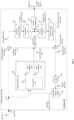
- FIG. 3 shows an example of a video decoder 30 that is configured to implement the techniques of this present application.
- the video decoder 30 is configured to receive encoded picture data 21 (e.g. encoded bitstream 21), e.g. encoded by encoder 20, to obtain a decoded picture 331.
- the encoded picture data or bitstream comprises information for decoding the encoded picture data, e.g. data that represents picture blocks of an encoded video slice (and/or tile groups or tiles) and associated syntax elements.
- the decoder 30 comprises an entropy decoding unit 304, an inverse quantization unit 310, an inverse transform processing unit 312, a reconstruction unit 314 (e.g. a summer 314), a loop filter 320, a decoded picture buffer (DBP) 330, a mode application unit 360, an inter prediction unit 344 and an intra prediction unit 354.
- Inter prediction unit 344 may be or include a motion compensation unit.
- Video decoder 30 may, in some examples, perform a decoding pass generally reciprocal to the encoding pass described with respect to video encoder 100 from FIG. 2 .
- the inverse quantization unit 210 may be identical in function to the inverse quantization unit 110
- the inverse transform processing unit 312 may be identical in function to the inverse transform processing unit 212
- the reconstruction unit 314 may be identical in function to reconstruction unit 214
- the loop filter 320 may be identical in function to the loop filter 220
- the decoded picture buffer 330 may be identical in function to the decoded picture buffer 230. Therefore, the explanations provided for the respective units and functions of the video 20 encoder apply correspondingly to the respective units and functions of the video decoder 30.
- the entropy decoding unit 304 is configured to parse the bitstream 21 (or in general encoded picture data 21) and perform, for example, entropy decoding to the encoded picture data 21 to obtain, e.g., quantized coefficients 309 and/or decoded coding parameters (not shown in FIG. 3 ), e.g. any or all of inter prediction parameters (e.g. reference picture index and motion vector), intra prediction parameter (e.g. intra prediction mode or index), transform parameters, quantization parameters, loop filter parameters, and/or other syntax elements.
- Entropy decoding unit 304 may be configured to apply the decoding algorithms or schemes corresponding to the encoding schemes as described with regard to the entropy encoding unit 270 of the encoder 20.
- Entropy decoding unit 304 may be further configured to provide inter prediction parameters, intra prediction parameter and/or other syntax elements to the mode application unit 360 and other parameters to other units of the decoder 30.
- Video decoder 30 may receive the syntax elements at the video slice level and/or the video block level.
- tile groups and/or tiles and respective syntax elements may be received and/or used.
- the inverse quantization unit 310 may be configured to receive quantization parameters (QP) (or in general information related to the inverse quantization) and quantized coefficients from the encoded picture data 21 (e.g. by parsing and/or decoding, e.g. by entropy decoding unit 304) and to apply based on the quantization parameters an inverse quantization on the decoded quantized coefficients 309 to obtain dequantized coefficients 311, which may also be referred to as transform coefficients 311.
- the inverse quantization process may include use of a quantization parameter determined by video encoder 20 for each video block in the video slice (or tile or tile group) to determine a degree of quantization and, likewise, a degree of inverse quantization that should be applied.
- the reconstruction unit 314 (e.g. adder or summer 314) may be configured to add the reconstructed residual block 313, to the prediction block 365 to obtain a reconstructed block 315 in the sample domain, e.g. by adding the sample values of the reconstructed residual block 313 and the sample values of the prediction block 365.
- the loop filter unit 320 (either in the coding loop or after the coding loop) is configured to filter the reconstructed block 315 to obtain a filtered block 321, e.g. to smooth pixel transitions, or otherwise improve the video quality.
- the loop filter unit 320 may comprise one or more loop filters such as a de-blocking filter, a sample-adaptive offset (SAO) filter or one or more other filters, e.g. a bilateral filter, an adaptive loop filter (ALF), a sharpening, a smoothing filter or a collaborative filters, or any combination thereof.
- the loop filter unit 320 is shown in FIG. 3 as being an in loop filter, in other configurations, the loop filter unit 320 may be implemented as a post loop filter.
- decoded video blocks 321 of a picture are then stored in decoded picture buffer 330, which stores the decoded pictures 331 as reference pictures for subsequent motion compensation for other pictures and/or for output respectively display.
- the decoder 30 is configured to output the decoded picture 311, e.g. via output 312, for presentation or viewing to a user.
- the inter prediction unit 344 may be identical to the inter prediction unit 244 (in particular to the motion compensation unit) and the intra prediction unit 354 may be identical to the inter prediction unit 254 in function, and performs split or partitioning decisions and prediction based on the partitioning and/or prediction parameters or respective information received from the encoded picture data 21 (e.g. by parsing and/or decoding, e.g. by entropy decoding unit 304).
- Mode application unit 360 may be configured to perform the prediction (intra or inter prediction) per block based on reconstructed pictures, blocks or respective samples (filtered or unfiltered) to obtain the prediction block 365.
- intra prediction unit 354 of mode application unit 360 is configured to generate prediction block 365 for a picture block of the current video slice based on a signaled intra prediction mode and data from previously decoded blocks of the current picture.
- inter prediction unit 344 e.g. motion compensation unit
- the prediction blocks may be produced from one of the reference pictures within one of the reference picture lists.
- Video decoder 30 may construct the reference frame lists, List 0 and List 1, using default construction techniques based on reference pictures stored in DPB 330.
- the same or similar may be applied for or by embodiments using tile groups (e.g. video tile groups) and/or tiles (e.g. video tiles) in addition or alternatively to slices (e.g. video slices), e.g. a video may be coded using I, P or B tile groups and /or tiles.
- a processing result of a current step may be further processed and then output to the next step.
- a further operation such as Clip or shift, may be performed on the processing result of the interpolation filtering, motion vector derivation or loop filtering.
- the value of motion vector is constrained to a predefined range according to its representing bit. If the representing bit of motion vector is bitDepth, then the range is - 2 ⁇ (bitDepth-1) ⁇ 2 ⁇ (bitDepth-1)-1, where " ⁇ " means exponentiation. For example, if bitdepth is set equal to 16, the range is -32768 ⁇ 32767; if bitDepth is set equal to 18, the range is - 131072 ⁇ 131071.
- the value of the derived motion vector (e.g. the MVs of four 4x4 sub-blocks within one 8x8 block) is constrained such that the max difference between integer parts of the four 4x4 sub-block MVs is no more than N pixels, such as no more than 1 pixel.
- N pixels such as no more than 1 pixel.
- the operations may be applied during the sum of mvp and mvd, as shown in formula (5) to (8).
- vx is a horizontal component of a motion vector of an image block or a sub-block
- vy is a vertical component of a motion vector of an image block or a sub-block
- x, y and z respectively correspond to three input value of the MV clipping process
- FIG. 4 is a schematic diagram of a video coding device 400 according to an embodiment of the disclosure.
- the video coding device 400 is suitable for implementing the disclosed embodiments as described herein.
- the video coding device 400 may be a decoder such as video decoder 30 of FIG. 1A or an encoder such as video encoder 20 of FIG. 1A .
- the video coding device 400 comprises ingress ports 410 (or input ports 410) and receiver units (Rx) 420 for receiving data; a processor, logic unit, or central processing unit (CPU) 430 to process the data; transmitter units (Tx) 440 and egress ports 450 (or output ports 450) for transmitting the data; and a memory 460 for storing the data.
- the video coding device 400 may also comprise optical-to-electrical (OE) components and electrical-to-optical (EO) components coupled to the ingress ports 410, the receiver units 420, the transmitter units 440, and the egress ports 450 for egress or ingress of optical or electrical signals.
- OE optical-to-electrical
- EO electrical-to-optical
- the processor 430 is implemented by hardware and software.
- the processor 430 may be implemented as one or more CPU chips, cores (e.g., as a multi-core processor), FPGAs, ASICs, and DSPs.
- the processor 430 is in communication with the ingress ports 410, receiver units 420, transmitter units 440, egress ports 450, and memory 460.
- the processor 430 comprises a coding module 470.
- the coding module 470 implements the disclosed embodiments described above. For instance, the coding module 470 implements, processes, prepares, or provides the various coding operations. The inclusion of the coding module 470 therefore provides a substantial improvement to the functionality of the video coding device 400 and effects a transformation of the video coding device 400 to a different state.
- the coding module 470 is implemented as instructions stored in the memory 460 and executed by the processor 430.
- the memory 460 may comprise one or more disks, tape drives, and solid-state drives and may be used as an over-flow data storage device, to store programs when such programs are selected for execution, and to store instructions and data that are read during program execution.
- the memory 460 may be, for example, volatile and/or non-volatile and may be a read-only memory (ROM), random access memory (RAM), ternary content-addressable memory (TCAM), and/or static random-access memory (SRAM).
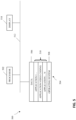
- FIG. 5 is a simplified block diagram of an apparatus 500 that may be used as either or both of the source device 12 and the destination device 14 from FIG. 1 according to an exemplary embodiment.
- a processor 502 in the apparatus 500 can be a central processing unit.
- the processor 502 can be any other type of device, or multiple devices, capable of manipulating or processing information now-existing or hereafter developed.
- the disclosed implementations can be practiced with a single processor as shown, e.g., the processor 502, advantages in speed and efficiency can be achieved using more than one processor.
- a memory 504 in the apparatus 500 can be a read only memory (ROM) device or a random-access memory (RAM) device in an implementation. Any other suitable type of storage device can be used as the memory 504.
- the memory 504 can include code and data 506 that is accessed by the processor 502 using a bus 512.
- the memory 504 can further include an operating system 508 and application programs 510, the application programs 510 including at least one program that permits the processor 502 to perform the methods described here.
- the application programs 510 can include applications 1 through N, which further include a video coding application that performs the methods described here.
- the apparatus 500 can also include one or more output devices, such as a display 518.
- the display 518 may be, in one example, a touch sensitive display that combines a display with a touch sensitive element that is operable to sense touch inputs.
- the display 518 can be coupled to the processor 502 via the bus 512.
- the bus 512 of the apparatus 500 can be composed of multiple buses.
- the secondary storage 514 can be directly coupled to the other components of the apparatus 500 or can be accessed via a network and can comprise a single integrated unit such as a memory card or multiple units such as multiple memory cards.
- the apparatus 500 can thus be implemented in a wide variety of configurations.
- HLS High Level Signaling
- the high-level syntax provides the encapsulation for the coded video data for further processing. It structures the information for transport and makes it accessible and also searchable. It further provides means to code all specified high-level parameters and additional side information. In order to separate between the encoded information and the form in which this information is represented, a Video Coding Layer (VCL) and a Network Abstraction Layer (NAL) are defined. All VCL and non-VCL data are encapsulated in NAL units for transmission. These concepts are further detailed below.
- VCL Video Coding Layer
- NAL Network Abstraction Layer
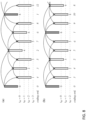
- the coding order of the pictures in fact corresponds to the output order, i.e. the order in which the pictures should be displayed.
- each picture uses a single reference picture for prediction. Prediction from a single reference is called uni-prediction. Historically, such pictures are called P pictures.
- the coding structure further exhibits a certain hierarchy of the pictures. For example, the pictures with odd output numbers may be dropped without impacting the decodability of the other pictures.
- the coding structure of the other pictures is independent of these pictures.
- every fourth picture can be decoded without impact from the intermediate pictures with even output numbers. Such a structure is called a hierarchical coding structure.
- peak_bitrate- the peak_bitrate is maximum allowable bitrate that the underlying network can assign to the MMT stream.
- the peak_bitrate is expressed in kilobits per second. Overhead for the protocols of the underlying network is not included.
- the current_delay parameter indicates the last hop transport delay.
- the current_delay expressed in milliseconds.
- SDU_size - SDU Service Data Unit
- SDU_size is data unit in which the underlying network delivers the MMT data.
- the SDU_size specifies the length of the SDU and is expressed in bits. Overhead for the protocols of the underlying network is not included.
- BER - Bit Error Rate obtained from PHY or MAC layer.
- this value present as a positive value.
- BER from MAC layer this value present as a negative value which can be used as an absolute value.
- AVC streams are stored in any file of the ISO base media file format family, such as MP4 [2].
- These video streams are a sequence of access units, divided into NAL units.
- Each access unit is a file format sample, and the access units have a size indication in front of each one. That length indication can be configured as 1, 2 or 4 bytes. Start codes are not used.
- Timing information comes from the structures in the file format; timing information embedded in the video layer is not used.
- SVC and MVC it is possible to store layers (SVC) or views (MVC) in more than one track; special structures called Extractors a can be used under some circumstances to indicate how to 'complete' a track by drawing NAL units from other track(s).
- Extractors a There is a structure similar to an Extractor, called an Aggregator, which can be used to group NAL units.
- a temporal meta-data track may be associated with a video track, to describe the structure of each access unit in the desired level of detail. These temporal meta-data tracks make 'statements' about the time-parallel access unit, or part of an access unit, to which they are linked.
- Shutter angle is a term and parameter of cinematic art that indicates shutter interval relative to frame interval. The concept and use of shutter angle was developed in the cinema industry where content has historically been created at fixed 24 fps. In cinema, shutter angle is an indicator of motion smoothness and picture sharpness. Small values of shutter angle (short shutter interval) are associated with more stutter and non-smooth motion but sharp pictures. Large values of shutter angle (long shutter interval) are associated with smooth but blurrier pictures as a result of temporal summation (motion blur).
- Short shutter interval relative to frame interval results in more stutter and non-smooth perceived motion compared to long shutter interval relative to frame interval (large value for shutter angle), particularly for low frame rates.
- Shutter interval as an independent parameter, and shutter interval relative to frame interval (shutter angle) are parameters that are used purposefully to adjust the look of video, particularly for professionally created content.
- the coded picture rate may be different than the original frame rate. Consequently, the shutter interval relative to the coded picture interval (inverse of coded picture rate) would be different than the shutter interval relative to the original frame interval. As a result, the look of the coded video may be different than was originally intended by the content creator.
- the effective shutter interval may be artificially modified by a display or other post-decode process to affect the look of displayed video.
- synthetic motion blur may be increased or decreased to achieve a desired look.
- bitstreams could be extracted at multiple picture rates. For example, as illustrated in FIG. 10 , a 60 Hz video sequence can be derived from a 120 Hz progressive video sequence by dropping every other picture. Similarly, a 30 Hz video sequence can be derived by dropping 3 out of every 4 pictures, and a 24 Hz video sequence can be derived by dropping 4 out of every 5 pictures.
- the shutter interval is independent of the picture rate of the extracted bitstream.
- the shutter interval relative to the picture interval (the shutter angle) of each of the resulting videos would be different and may thus result in a different look.
- motion in the 24 fps (24 Hz) video would have more stutter and be less smooth than the 120 Hz video.
- the fidelity of extracted temporal sub-layers to the visual look of the original video sequence is an important component of meeting quality expectations in broadcast use cases, including those that use temporal sub-layering as specified in ATSC 3.0.
- JVET-M0579 also discusses the ATSC 3.0 Multiple Frame Rate Temporal Filtering Tool to support both high and low frame rates in a backward-compatible manner whilst avoiding stutter and non-smooth motion.
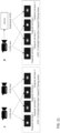
- the key concepts of the ATSC tool are illustrated in FIG. 11 , which are based on the ATSC 3.0 specification.
- temporal sub-layer 0 may be composed of pictures having a long shutter interval and temporal sub-layer 1 may be composed of pictures having a short shutter interval.
- Temporal sub-layers 0 and 1 may be sourced from different camera feeds ( FIG. 2 , panel A) or sub-layer 0 may be synthesized from the high frame rate camera feed (panel B).
- Draft Rec. ITU-T H.SEI Draft ISO/IEC 23002-7 specification does not provide shutter interval information to displays or other post-decode processes to facilitate achieving a consistent or other desired look for different extracted temporal sub-layers.
- a display or other post decoding process that also had access to frame rate information (or equivalent) could simulate a longer or shorter shutter interval using synthetic motion blur or other method.
- a display might add motion blur in the 24 Hz example to reduce stutter and non-smooth motion.
- a value of ShutterInterval greater than the value of the inverse of the coded picture rate, the coded picture interval, may indicate that the coded picture rate is greater than the picture rate at which the associated video content was created - e.g., when the coded picture rate is 120 Hz and the picture rate of the associated video content prior to encoding and display is 60 Hz.
- the coded interval for the given temporal sub-layer Tid may be indicated by ClockTick and elemental_duration_in_tc_minus1[Tid].
- sub_layer_shutter_interval_numer[ i] specifies the numerator used to derive sub layer shutter interval, defined by variable subLayerShutterInterval[i], in units of seconds, when HighestTid is equal to i.
- sub_layer_shutter_interval_denom [i] specifies the denominator used to derive sub layer shutter interval, defined by variable subLayerShutterInterval[i], in units of seconds, when HighestTid is equal to i.
- subLayerShutterInterval[i] should be interpreted as unkown or unspecified.
- subLayerShutterInterval[i] ShutterInterval
- the shutter interval information SEI message indicates the shutter interval for the associated video content prior to encoding and display - e.g., for camera-captured content, the amount of time that an image sensor was exposed to produce a picture.
- sii_num_units_in_shutter specifies the number of time units of a clock operating at the frequency sii_time_scale Hz that corresponds to one increment of an shutter clock tick counter.
- Shutter interval defined by variable ShutterInterval, in units of seconds, is equal to the quotient of sii_num_units_in_shutter_interval divided by sii_time_scale. For example, when ShutterInterval is equal to 0.04 seconds, sii_time_scale may be equal to 27 000 000 and sii_num_units_in_shutter_interval may be equal to 1 080 000.
- sii_time_scale specifies the number of time units that pass in one second. For example, a time coordinate system that measures time using a 27 MHz clock has a sii_time_scale of 27 000 000.
- ShutterInterval sii_num_units_in_shutter_interval ⁇ sii_time_scale
- ShutterInterval should be interpreted as unknown or unspecified.
- NOTE 1 - A value of ShutterInterval equal to 0 may indicate that the associated video content contain screen capture content, computer generated content, or other non-camera-capture content.
- a value of ShutterInterval greater than the value of the inverse of the coded picture rate, the coded picture interval may indicate that the coded picture rate is greater than the picture rate at which the associated video content was created - e.g., when the coded picture rate is 120 Hz and the picture rate of the associated video content prior to encoding and display is 60 Hz.
- the coded picture interval for the given temporal sub-layer Tid may be indicated by ClockTick and elemental_duration_in_tc_minus1[Tid].
- PictureInterval[Tid] ClockTick * (elemental_duration_in_tc_minus1[Tid] + 1).
- fixed_shutter_interval_within_cvs_flag 1 specifies that the value of ShutterInterval is the same for all temporal sub-layers in the CVS.
- fixed_shutter_interval_within_cvs_flag 0 specifies that value of ShutterInterval may not be the same for all temporal sub-layers in the CVS.
- sub_layer_num_units_in_shutter_interval[i] specifies the number of time units of a clock operating at the frequency sii_time_scale Hz that corresponds to one increment of an shutter clock tick counter.
- subLayerShutterInterval i sub_layer_num_units_in_shutter_interval i ⁇ sii_time_scale
- subLayerShutterInterval[i] should be interpreted as unknown or unspecified.
- subLayerShutterInterval[i] ShutterInterval
- Layered (scalable) approach is included to specification in order to provide adaptation to variable channel bandwidth and for error resilience needs.
- Temporal sub-layers is a part of such approach and only one which supported by VVC draft of specification at the time when this document is written.
- FIG. 9 Switching content for temporal sub-stream extraction.
- sps_max_sub_layers_minus1 plus 1 could be used for correct derivation of Temporal ID corresponding to target picture rate by using delta between Highest TID of corresponding CVS and target TID, but according to semantic of this parameter some CVS associated to particular SPS could contain highest temporal ID less than sps_max_sub_layers_minus1 plus 1. This means that there are no guarantee for correct recognition of appropriate Temporal ID for our scenario.
- decoder control is the buffer management for the decoded pictures as well as for the incoming bitstream.
- Decoded pictures in the decoded picture buffer may be further used for reference in the decoding process. Further, in systems that operate at a defined picture rate for presentation, it must be asserted that the decoding process makes the decoded pictures available for display according to the timing constraints imposed by the employed format.
- Another ability to derive picture rate is Structure of Pictures Information SEI message which describes the coding structure including used reference picture set for a SOP and which persists for the AUs associated to the SOP.
- This approach is a bit more complicated if we need to inform the decoder about resulted picture rate for the few trailing pictures. Moreover, it requires an additional derivation process from the data available in this SEI message. Moreover, this SEI message needs to be transmitted for each individual SOP and can't guarantee the resulted frame rate for some appropriate period of time. The application/player is required to be smart enough to control appropriate temporal ID for each SOP (like picture rate control).
- MDC Multi Description Coding
- AVC and HEVC have scalable extensions, which allows to have subbitstreams embedded into the one stream. It is achieved by using Temporal, Spatial and SNR scalabilities.
- Each level of scalability is represented by an own layer ID.
- the set layers of different scalability may be represented by collective term Layer ID that consist of a set of sub-layers of different nature.
- Temporal scalability operates in the temporal domain by distributing reference relations between pictures so that some subset of pictures may be discarded by network or other application without losing the ability to correctly decode the remaining part of the stream.
- Spatial scalability allows redistributing media data between pictures of different spatial resolutions with referencing from higher layers with higher resolutions to lower layers with smaller resolutions.
- SNR scalability allows redistributing bits of the same picture in a same resolution but with different level of quality (encoded with a different level of quantization for example).
- Scalable extension of VVC may reuse temporal scalability design for spatial and SNR scalability in the similar manner as it was proposed in JVET-00045 and JVET-O0333 by defining a bitstream extraction process almost identical to the one for temporal scalability.
- POC values of each picture could be used for needs different from temporal domain.
- JVET-P0338 Two variations of the syntax and semantics for a shutter interval information SEI message are presented below. These variations differ with respect to signalling of a shutter interval for sub layers.
- the first variation signals a pair of values to form a ratio.
- the second variation signals a single value. Both variations support signalling as described in the following:
- JVET-P0338 The problem as well as the solution described in JVET-P0338 is the parsing dependency of a parameter spsmax_sub_layers_minus1, and derivation of a parameter ClockTick when fixed_shutter_ interval _within _cvs_flag equal to 1.
- the present disclosure discloses the following aspects (each of them can be applied individually and some of them can be applied in combination):
- the terms Maximum Temporal ID and Highest Temporal ID should be understood to have the same meaning.
- the new SEI message with title "Sub-Layer Picture rates SEI message" is proposed in order to provide to the external application or network the list of picture rates associated with the list of Temporal IDs.
- pr_max_sub_layers_minus1 plus 1 specifies the maximum number of temporal sub-layers that may be present in each CVS referring to the SPS.
- the value of pr_max_sub_layers_minus1 shall be in the range of 0 to 6, inclusive.
- pr_time_scale is the number of time units that pass in one second. For example, a time coordinate system that measures time using a 27 MHz clock has a time_scale of 27 000 000. The value of time_scale shall be greater than 0.
- dyadic_temporal_nesting_flag indicates that the Temporal IDs are distributed hierarchically with dyadic dependencies. When not present the value of dyadic_temporal_nesting_flag is inferred to be equal to 0.
- sub_layer_num_units_in_tick[i] is the number of time units of a clock operating at the frequency pr_time_scale Hz that corresponds to one increment (called a clock tick) of a clock tick counter.
- sub_layer_num_units_in_tick[i] shall be greater than 0.
- a clock tick, in units of seconds, is equal to the quotient of sub_layer_num_units_in_tick divided by pr_time_scale.
- pr_time_scale may be equal to 27 000 000 and sub_layer_num_units_in_tick may be equal to 1 080 000, and consequently a clock tick may be equal to 0.04 seconds.
- the access unit containing the SEI message Decoding unit information The access unit containing the SEI message Frame-field information
- the access unit containing the SEI message Sub-Layer Picture Rates The CVS
- Additional syntax element is proposed to include into sub_layer_hrd_parameters syntax in order to provide to the external application or network the list of picture rates associated with the list of Temporal IDs.
- general_hrd_parameters ( firstSubLayer, maxNumSubLayersMinus1 ) ⁇ Descripto r general_nal_hrd_parameters_present_flag u(1) general_vcl_hrd_parameters_present_flag u(1) if(general _nal_hrd_parameters_present_ flag
- dyadic_temporal_nesting_flag indicates that the Temporal IDs are distributed hierarchically with dyadic dependencies. When not present the value of dyadic_temporal_nesting_flag is inferred to be equal to 0.
- sub_layer_num_units_in_tick[i] is the number of time units of a clock operating at the frequency pr_time_scale Hz that corresponds to one increment (called a clock tick) of a clock tick counter.
- sub_layer_num_units_in_tick[ i] shall be greater than 0.
- a clock tick, in units of seconds, is equal to the quotient of sub_layer_num_units_in_tick divided by time_scale. For example, when the picture rate of a video signal is 25 Hz, time_scale may be equal to 27 000 000 and sub_layer_num_units_in_tick may be equal to 1 080 000, and consequently a clock tick may be equal to 0.04 seconds.
- sub_layer_num_units_in_tick[max_sub_layers_minus1 ] is set equal to num_units_in_tick.
- the new SEI message with title "Sub-Layer Picture Intervals SEI message” is proposed in order to provide to the external application or network the list of picture intervals associated with the list of Temporal IDs.
- pi_max_sub_layers_minus1 or pr_max_sub_layer_minus1 shallbe in the range of 0 to 6, inclusive. of 0 to 6, inclusive
- pi_time_scale is the number of time units that pass in one second.
- a time pi_time_scale is the number of time units that pass in one second.
- a time coordinate system that measures time using a 27 MHz clock has a time_scale of 27 000 000.
- time_scale shall be grater than 0.
- dyadic_temporal_nesting_flag indicates that the temporal IDs are distributed hierarchially with dyadic dependercies .
- dyadic_temporal_nesting_flag is inferred to be equal to 0.
- sub_layer_num_units_in_tick[i] is the number of time units of a clock operating at the frequency pi_time_scale Hz that corresponds to one increment (called a clock tick) of a clock tick counter sub_layer_num_units_in_tick[i] shall be greater than 0.
- a clock tick, in units of second, is equal to the quotient of sub_layer_num_units_in_tick[i] divided by pi_time_sale. For example, when the picture rate of a video signal is 25 Hz, pi_time_scale may be equal to 27 000 000 and sub_layer_num_units_in_tick may be equal to 1 080 000 and consequently a clock tick may be equal to 0.04 seconds.
- PictureInterval should be interpreted as unknown or unspecified.
- sub_layer_num_units_in_tick[i] and sub_layer_num_units_in_shutter_interval[ i ] for i from 0 to pi max_sub_layer_minus1-1 are derived as follows: For each value of i in the range of 0 pi_max_sub_layers_minus1-1, inclusive, the variable sub_layer_num_units_in_tick[ i ] is derived as follows:
- sub_layer_num_units_in_shutter_interval [ i ] specifies the number of time units of a clock operating at the freqency pi_time_scale Hz that corresponds to one increment of an shutter clock tick counter.
- Shutter interval defined by variable ShutterInterval, in units of seconds, is equal to the quotient of sub_layer_num_units_in_shutter_interval[ pi_max_sub_layers_minus1 ] divided by p_time_scale.
- pi_time_scale may be equal to 27 000 000 and sub_layer_num_units_in_shutter_interval[ pi_max_sub_layers_minus1 ] may be equal to 1 080 000.
- ShutterInterval should be interpreted as unknown or unspecified.
- the new SEI message with title "Sub-Layer Picture Intervals SEI message” is proposed in order to provide to the external application or network the list of picture intervals associated with the list of Temporal IDs.
- pi_max_sub_layers_minus1 or pr_max_sub_layer_minus1 shall be in the range of 0 to 6, inclusive. It is a requirement of bitstream conformance that the value of pi_max_sub_layers_minus1 or pr_max_sub_layer_minus1 in the picture rates SEI message is equal to the value of sps_max_sub_layers_minus1 un the SPS.
- pi_time_scale is the number of time units that pass in one second. For example, a time coordinte system that measures time using a 27 MHz clock has a time_scale of 27 000 000.
- time_scale shall be greater than 0. It is a requirement of bitstream conformance that the value of pi_time_scale in the picture rates
- SEI message is equal to the value of time_scale in the SPS.
- dyadic_temporal_nesting_flag indicated that the Temporal IDs are distributed hiderarically with dyadic dependencies.
- the value of dyadic_temporal_nesting_flag is inferred to be equal to 0.
- sub_layer_num_units_in_tick[ i ] is the nember of time units of a clock operating at the fraquency pi_time_scale Hz that corresponds to one increment (called a clock tick) of a clock tick conter sub_layer_num_units_in_tick[ i ]shall be greater than 0.
- a clock tick, in units of seconds, is equal to the quotient of sub_layer_num_units_in_tick[ i ] divided by pi_time_scale.
- pi_time_scale when the picture rate of a video signal is 25 Hz, pi_time_scale may be equal to 27 000 000 and sub_layer_num_units_in_tick may be equal to 1 080 000, and consequently a clock tick may be equal to 0.04 seconds.
- the value of pi_time_scale is greater than 0, the value of PictureInterval is specified by:
- PictureInterval should be interpreted as unknown or unspecified.
- sub_layer_num_units_in_tick[ i ] and sub_layer_num_units_in_shutter_interval[ i ] for i form 0 to pi_max_sub_layers_minus1-1 are derived as follows: For each value of i in the range of 0 to pi_max_sub_layers_minus1-1, inclusive, the variable sub_layer_num_units_in_tick[ i ] is derived as follows: fixed_shutter_interval_within_sublayer_flag [ i ] equal to 1 specifies that the value of ShutterInterval is the same for i th temporal sub-layer in the C(L)VS. fixed_shutter_interval_within_sublayer_flag [ i ] equal to 0 specifies that the value of ShutterInterval may not be the same for i th temopral sub-layer in the
- sub_layer_num_units_in_shutter_interval [ i ] specifies the number for time units of a clock operating at the frequenci pi_time_scale Hz that corresponds to one increment of an shutter clock tick counter for i th temporal sub-layer in the C(L)VS.
- Shutter interval difined by variable ShutterInterval, in units of seconds, is equal to the quotient of sub_layer_num_units_in_shutter_interval[ pi_max_sub_layers_minus1 ] devided by pi_time_scale.
- pi_time_scale may be equal to 27 000 000 and sub_layer_num_units_in_shutter_interval[ pi_max_sub_layers_minus1 ] may be equal to 1 080 000.
- the value of pi_time_scale is specified by:
- ⁇ ShutterInterval should be interpreted as unknown or unspecified.
- NOTE 1 - A value of ShutterInterval equal to 0 may indicate that the associated video content conatin screen capture content, computer generated content, or other non-camera-capture content.
- a value of ShutterInterval greater than the value of the inverse of the coded picture rate, the coded picture interval may indicate that the coded picture rate is greater than the picture rate at which the associated video content was created - e.g., when the coded picture rate is 120 Hz and the picture rate of the associated video content prior to encoding and display is 60Hz.
- the coded picture interval for the given temporal sub-layer Tid may be indicated by PictureInterval[ Tid ].
- the new SEI message with title "Sub-Layer Picture Intervals SEI message” is proposed in order to provide to the external application or network the list of picture intervals associated with the list of Temporal IDs.
- pi_max_sub_layers_minus1 plus 1 specifies the maximum number of temporal sub-layers that may be present in each C(L)VS referring to the SPS.
- the value of pi_max_sub_layers_minus1 or pr_mac_sub_layers_minus shall be in the range of 0 to 6, inclusive.
- pi_time_scale is the number of time units that pass in one second. For example, a time coordinate system that measures time using a 27 MHz clock had a time_scale of 27 000 000. The value of time_scale shall be greater than 0. It is a requirement of bitstream conformance that the value of pi_time_scale in the picture rates SEI message is equal to the value of time_scale in the SPS.
- dyadic_temporal_nesting_flag indicates that the Temporal IDs are distributed hierarchically with dyadic dependencies. When not present the value of dyadic_nesting_flag is inferred to be equal to 0.
- sub_layer_num_units_in_thick[ i ] is the number of time units of a clock operating at the frequency pi_time_scale Hz that correspond to one increment (called a clock tick) of a clock tick counter.
- sub_layer_num_units_in_tick[ i] ] shall be greater than 0.
- PictureInterval should be interpreted as unknown or unspecified.
- sub_layer_num_units_in_tick[ i ] ans sub_layer_num_in_shutter_interval[ i ] for i from 0 to pi_max_sub_layers_minus1-1 are derived as follows: For each value of i in the range of 0 to pi_max-sub_layers_minus1-1, inclusive, the variable sub_layer_num_units_in_tick[ i ] is derived as follows: fixed_shutter_interval_within_cvs_flag equal to 1 specifies that the value of ShutterInterval is the same for all temporal sub-layers in the C(L)VS. fixed_shutter_interval_within_sublayer_flag equal to 0 specifies that the value of ShutterInterval may not be the same for all temporal sub-layers in the C(L)VS.
- sub_layer_num_units_in_shutter_interval[ i ] specifies the number of time units of a clock operating at the frequency pi_time_scale Hz that corresponds to one increment of an shutter clock tick counter for i th temporal sub-layers in the C(L)VS.
- Shutter interval defined by variable ShutterInterval, in units of seconds, in equal to the quotient of sub_layer_num_units_in_shutter_interval[ pi_max_sub_layers_minus1 ] divided by pi_time_scale. For example, when ShutterInteral is equal to 0.04 seconds, pi_time_scale may be equal to 27 000 000 and sub layer num units in shutter interval[ pi_max_sub_layers_minus1 ] may be equal to 1 080 000.
- ShutterInterval should be interpreted as unknown or unspecified.
- NOTE 1 - A value of ShutterInterval equal to 0 may indicate that the associated video content contain screen capture content, computer generated content, or other non-camera-capture content.
- a value of ShutterInterval greater than the value of the inverse of the coded picture rate, the coded picture interval, may indicate that the picture rate is greater than the picture rate at which the associated video content was created - e.g., when the coded picture rate is 120 Hz and the picture rate of the associated video content prior to encoding and display is 60 Hz.
- the coded picture interval for the given temporal sub-layer Tid may be indicated by PictureInterval[ Tid ].
- FIG 14 illustrates a flowchart of a method according to the present disclosure.
- the method illustrated in FIG. 14 is a method of coding implemented by a decoding/encoding device for coding video data, according to an embodiment of the present disclosure.
- the method of FIG. 14 comprises the following steps: (1601) coding, in a supplemental enhancement information, SEI, message, a set of sequence parameters, wherein the set of sequence parameters is associated with temporal IDs of sub-layers of a bitstream or coded layer video sequence, C(L)VS; and (1602) processing the bitstream or C(L)VS by using the set of sequence parameters included in the SEI message; wherein the set of sequence parameters is used for deriving or representing a picture rate of the sequence.
- FIG. 15 illustrates a decoder according to the present disclosure.
- the decoder 30 illustrated in FIG. 15 is a decoder according to an embodiment of the present disclosure.
- the decoder 30 of FIG. 15 comprises: a decoding unit 3001 configured to decode, in a supplemental enhancement information, SEI, message, a set of sequence parameters, wherein the set of sequence parameters is associated with temporal IDs of sub-layers of a bitstream or coded layer video sequence, C(L)VS; and a processing unit 3003 configured to process the bitstream or C(L)VS by using the set of sequence parameters included in the SEI message; wherein the set of sequence parameters is used for deriving or representing a picture rate of the sequence.
- a decoding unit 3001 configured to decode, in a supplemental enhancement information, SEI, message, a set of sequence parameters, wherein the set of sequence parameters is associated with temporal IDs of sub-layers of a bitstream or coded layer video sequence, C(L)VS
- FIG. 16 illustrates an encoder according to the present disclosure.
- the encoder 20 illustrated in FIG. 16 is an encoder according to an embodiment of the present disclosure.
- the encoder 20 of FIG. 16 comprises: an encoding unit 2001 configured to encode, in a supplemental enhancement information, SEI, message, a set of sequence parameters, wherein the set of sequence parameters is associated with temporal IDs of sub-layers of a bitstream or coded layer video sequence, C(L)VS;
- a processing unit 2003 configured to process the bitstream or C(L)VS by using the set of sequence parameters included in the SEI message; wherein the set of sequence parameters is used for deriving or representing a picture rate of the sequence.
- FIG. 12 illustrates a block diagram showing a content supply system 3100 for realizing content distribution service.
- This content supply system 3100 includes capture device 3102, terminal device 3106, and optionally includes display 3126.
- the capture device 3102 communicates with the terminal device 3106 over communication link 3104.
- the communication link may include the communication channel 13 described above.
- the communication link 3104 includes but not limited to WIFI, Ethernet, Cable, wireless (3G/4G/5G), USB, or any kind of combination thereof, or the like.
- the capture device 3102 generates data, and may encode the data by the encoding method as shown in the above embodiments. Alternatively, the capture device 3102 may distribute the data to a streaming server (not shown in the Figures), and the server encodes the data and transmits the encoded data to the terminal device 3106.
- the capture device 3102 includes but not limited to camera, smart phone or Pad, computer or laptop, video conference system, PDA, vehicle mounted device, or a combination of any of them, or the like.
- the capture device 3102 may include the source device 12 as described above.
- the video encoder 20 included in the capture device 3102 may actually perform video encoding processing.
- an audio encoder included in the capture device 3102 may actually perform audio encoding processing.
- the capture device 3102 distributes the encoded video and audio data by multiplexing them together.
- the encoded audio data and the encoded video data are not multiplexed.
- Capture device 3102 distributes the encoded audio data and the encoded video data to the terminal device 3106 separately.
- the terminal device 310 receives and reproduces the encoded data.
- the terminal device 3106 could be a device with data receiving and recovering capability, such as smart phone or Pad 3108, computer or laptop 3110, network video recorder (NVR)/ digital video recorder (DVR) 3112, TV 3114, set top box (STB) 3116, video conference system 3118, video surveillance system 3120, personal digital assistant (PDA) 3122, vehicle mounted device 3124, or a combination of any of them, or the like capable of decoding the above-mentioned encoded data.
- the terminal device 3106 may include the destination device 14 as described above.
- the encoded data includes video
- the video decoder 30 included in the terminal device is prioritized to perform video decoding.
- an audio decoder included in the terminal device is prioritized to perform audio decoding processing.
- the terminal device can feed the decoded data to its display.
- NVR network video recorder
- DVR digital video recorder
- TV 3114 TV 3114
- PDA personal digital assistant
- vehicle mounted device 3124 the terminal device can feed the decoded data to its display.
- NVR network video recorder
- DVR digital video recorder
- TV 3114 TV 3114
- PDA personal digital assistant
- vehicle mounted device 3124 the terminal device can feed the decoded data to its display.
- a terminal device equipped with no display for example, STB 3116, video conference system 3118, or video surveillance system 3120, an external display 3126 is contacted therein to receive and show the decoded data.
- the picture encoding device or the picture decoding device can be used.
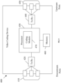
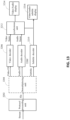
- FIG. 13 illustrates a diagram showing a structure of an example of the terminal device 3106.
- the protocol proceeding unit 3202 analyzes the transmission protocol of the stream.
- the protocol includes but not limited to Real Time Streaming Protocol (RTSP), Hyper Text Transfer Protocol (HTTP), HTTP Live streaming protocol (HLS), MPEG-DASH, Real-time Transport protocol (RTP), Real Time Messaging Protocol (RTMP), or any kind of combination thereof, or the like.
- RTSP Real Time Streaming Protocol
- HTTP Hyper Text Transfer Protocol
- HLS HTTP Live streaming protocol
- RTP Real-time Transport protocol
- RTMP Real Time Messaging Protocol
- stream file is generated.
- the file is outputted to a demultiplexing unit 3204.
- the demultiplexing unit 3204 can separate the multiplexed data into the encoded audio data and the encoded video data.
- the encoded audio data and the encoded video data are not multiplexed.
- the encoded data is transmitted to video decoder 3206 and audio decoder 3208 without through the demultiplexing unit 3204.
- video elementary stream (ES), audio ES, and optionally subtitle are generated.
- the video decoder 3206 which includes the video decoder 30 as explained in the above-mentioned embodiments, decodes the video ES by the decoding method as shown in the above-mentioned embodiments to generate video frame, and feeds this data to the synchronous unit 3212.
- the audio decoder 3208 decodes the audio ES to generate audio frame, and feeds this data to the synchronous unit 3212.
- the video frame may store in a buffer (not shown in FIG. 11 ) before feeding it to the synchronous unit 3212.
- the audio frame may store in a buffer (not shown in FIG. 11 ) before feeding it to the synchronous unit 3212.
- the synchronous unit 3212 synchronizes the video frame and the audio frame, and supplies the video/audio to a video/audio display 3214.
- the synchronous unit 3212 synchronizes the presentation of the video and audio information.
- Information may code in the syntax using time stamps concerning the presentation of coded audio and visual data and time stamps concerning the delivery of the data stream itself.
- the subtitle decoder 3210 decodes the subtitle, synchronizes it with the video frame and the audio frame, and supplies the video/audio/subtitle to a video/audio/subtitle display 3216.
- the present disclosure is not limited to the above-mentioned system, and either the picture encoding device or the picture decoding device in the above-mentioned embodiments can be incorporated into other system, for example, a car system.
- x y Used to denote division in mathematical equations where no truncation or rounding is intended.
- na When a relational operator is applied to a syntax element or variable that has been assigned the value "na” (not applicable), the value "na” is treated as a distinct value for the syntax element or variable. The value “na” is considered not to be equal to any other value.
- the table below specifies the precedence of operations from highest to lowest; a higher position in the table indicates a higher precedence.
- embodiments of the present disclosure have been primarily described based on video coding, it should be noted that embodiments of the coding system 10, encoder 20 and decoder 30 (and correspondingly the system 10) and the other embodiments described herein may also be configured for still picture processing or coding, i.e. the processing or coding of an individual picture independent of any preceding or consecutive picture as in video coding.
- inter-prediction units 244 (encoder) and 344 (decoder) may not be available in case the picture processing coding is limited to a single picture 17. All other functionalities (also referred to as tools or technologies) of the video encoder 20 and video decoder 30 may equally be used for still picture processing, e.g.
- residual calculation 204/304 transform 206, quantization 208, inverse quantization 210/310, (inverse) transform 212/312, partitioning 262/362, intra-prediction 254/354, and/or loop filtering 220, 320, and entropy coding 270 and entropy decoding 304.
- Embodiments, e.g. of the encoder 20 and the decoder 30, and functions described herein, e.g. with reference to the encoder 20 and the decoder 30, may be implemented in hardware, software, firmware, or any combination thereof. If implemented in software, the functions may be stored on a computer-readable medium or transmitted over communication media as one or more instructions or code and executed by a hardware-based processing unit.
- Computer-readable media may include computer-readable storage media, which corresponds to a tangible medium such as data storage media, or communication media including any medium that facilitates transfer of a computer program from one place to another, e.g., according to a communication protocol.
- computer-readable media generally may correspond to (1) tangible computer-readable storage media which is non-transitory or (2) a communication medium such as a signal or carrier wave.
- Data storage media may be any available media that can be accessed by one or more computers or one or more processors to retrieve instructions, code and/or data structures for implementation of the techniques described in this disclosure.
- a computer program product may include a computer-readable medium.
- such computer-readable storage media can comprise RAM, ROM, EEPROM, CD-ROM or other optical disk storage, magnetic disk storage, or other magnetic storage devices, flash memory, or any other medium that can be used to store desired program code in the form of instructions or data structures and that can be accessed by a computer.
- any connection is properly termed a computer-readable medium.
- a computer-readable medium For example, if instructions are transmitted from a website, server, or other remote source using a coaxial cable, fiber optic cable, twisted pair, digital subscriber line (DSL), or wireless technologies such as infrared, radio, and microwave, then the coaxial cable, fiber optic cable, twisted pair, DSL, or wireless technologies such as infrared, radio, and microwave are included in the definition of medium.
- DSL digital subscriber line
- Disk and disc includes compact disc (CD), laser disc, optical disc, digital versatile disc (DVD), floppy disk and Blu-ray disc, where disks usually reproduce data magnetically, while discs reproduce data optically with lasers. Combinations of the above should also be included within the scope of computer-readable media.
- processors such as one or more digital signal processors (DSPs), general purpose microprocessors, application specific integrated circuits (ASICs), field programmable logic arrays (FPGAs), or other equivalent integrated or discrete logic circuitry.
- DSPs digital signal processors
- ASICs application specific integrated circuits
- FPGAs field programmable logic arrays
- processors may refer to any of the foregoing structure or any other structure suitable for implementation of the techniques described herein.
- the functionality described herein may be provided within dedicated hardware and/or software modules configured for encoding and decoding, or incorporated in a combined codec. Also, the techniques could be fully implemented in one or more circuits or logic elements.
- the techniques of this disclosure may be implemented in a wide variety of devices or apparatuses, including a wireless handset, an integrated circuit (IC) or a set of ICs (e.g., a chip set).
- IC integrated circuit
- a set of ICs e.g., a chip set.
- Various components, modules, or units are described in this disclosure to emphasize functional aspects of devices configured to perform the disclosed techniques, but do not necessarily require realization by different hardware units. Rather, as described above, various units may be combined in a codec hardware unit or provided by a collection of interoperative hardware units, including one or more processors as described above, in conjunction with suitable software and/or firmware.
Landscapes
- Engineering & Computer Science (AREA)
- Multimedia (AREA)
- Signal Processing (AREA)
- Computer Security & Cryptography (AREA)
- Compression Or Coding Systems Of Tv Signals (AREA)
Claims (6)
- Procédé de codage mis en œuvre par un dispositif de codage/décodage pour le codage de données vidéo, comprenant les étapes consistant à :coder, dans un message d'information d'amélioration supplémentaire, SEI, un ensemble de paramètres de séquence,dans lequel l'ensemble de paramètres de séquence est associé à des ID temporels de sous-couches d'un flux binaire ou d'une séquence vidéo en couches codée, C(L)VS ;traiter le flux binaire ou la C(L)VS au moyen de l'ensemble de paramètres de séquence contenu dans le message SEI ;dans lequel l'ensemble de paramètres de séquence est utilisé pour dériver ou représenter une fréquence d'image de la séquence ;dans lequel l'ensemble de paramètres de séquence contient un ou plusieurs des paramètres suivants : une valeur d'échelle de temps d'ID temporel, TID, le plus élevé indiquant le nombre d'unités de temps qui s'écoulent en une seconde, un indicateur de distribution d'ID temporels dyadique indiquant une fréquence d'image fixe et une distribution hiérarchique dyadique pour toutes les sous-couches à l'intérieur du flux binaire ou de la C(L)VS, un nombre d'unités de cycles élémentaires d'horloge associé à la fréquence d'image de la sous-couche correspondante à partir de la sous-couche d'ID temporel 0 pour une distribution de TID non dyadique, et un nombre d'unités de cycles élémentaires d'horloge associé à la fréquence d'image de la sous-couche correspondante à partir de l'ID temporel le plus élevé pour une distribution de TID dyadique jusqu'à la sous-couche de TID le plus élevé dans le flux binaire ou sous une forme de fréquence d'image de précision prédéfinie ;dans lequel l'ensemble de paramètres de séquence contient un indicateur de distribution d'ID temporels dyadique désignant une fréquence d'image fixe pour toutes les sous-couches à l'intérieur du flux binaire ou de la C(L)VS dans des éléments de syntaxe de paramètres HRD généraux, et dans lequel le traitement du flux binaire au moyen de l'ensemble de paramètres de séquence comprend les étapes consistant à :positionner la valeur d'un indicateur indiquant une fréquence d'image fixe à 1, lorsqu'un indicateur indiquant une imbrication temporelle dyadique est présent ;positionner la valeur d'un indicateur indiquant une fréquence d'image fixe dans la C(L)VS à 1 lorsqu'un indicateur indiquant une imbrication temporelle dyadique est présent ; ettraiter le flux binaire ou la C(L)VS sur la base de la valeur de l'indicateur indiquant la fréquence d'image fixe ;caractérisé en ce quele positionnement de la valeur d'un indicateur indiquant une fréquence d'image fixe à 1, lorsqu'un indicateur indiquant une imbrication temporelle dyadique est présent consiste à : positionner la valeur d'un indicateur appelé fixed_pic_rate_general_flag à 1 lorsque l'indicateur appelé dyadic_temporal_nesting_flag est égal à 1 ;dans lequel le positionnement de la valeur d'un indicateur indiquant une fréquence d'image fixe dans la C(L)VS à 1 lorsqu'un indicateur indiquant une imbrication temporelle dyadique est présent consiste à : positionner la valeur d'un indicateur appelé fixed_pic_rate_within_cvs_flag à 1 lorsque l'indicateur appelé dyadic_temporal_nesting_flag est égal à 1 ; etdans lequel le traitement du flux binaire ou de la C(L)VS sur la base de la valeur de l'indicateur indiquant la fréquence d'image fixe consiste à traiter le flux binaire ou la C(L)VS sur la base de la valeur de l'indicateur appelé fixed_pic_rate_flag.
- Procédé selon la revendication 1, dans lequel le codage de l'ensemble de paramètres de séquence associé aux ID temporels dans le message SEI consiste à coder une indication indiquant un type de charge utile particulier pour le message SEI.
- Procédé selon l'une quelconque des revendications 1 et 2, dans lequel les ID temporels sont associés à un sous-ensemble d'ID de couche généraux, dans lequel au moins un des ID de couche généraux est un ID de couche temporel, ou un ID de couche de rapport signal sur bruit, SNR, ou un ID de couche spatial.
- Procédé selon l'une quelconque des revendications 1 à 3, dans lequel l'ensemble de paramètres de séquence contient un nombre d'unités de cycles élémentaires d'horloge de TID le plus élevé, le TID le plus élevé, et le traitement du flux binaire ou de la C(L)VS au moyen de l'ensemble de paramètres de séquence comprend les étapes consistant à :
dériver un nombre d'unités de cycles élémentaires d'horloge pour une sous-couche associée à un TID particulier en divisant un nombre d'unités de cycles élémentaires d'horloge de TID le plus élevé par le (TID le plus élevé moins le TID actuel) à la puissance deux ; et traiter le flux binaire sur la base du nombre d'unités de cycles élémentaires d'horloge pour la sous-couche. - Décodeur, comprenant :une unité de décodage configurée pour décoder, dans un message d'information d'amélioration supplémentaire, SEI, un ensemble de paramètres de séquence,dans lequel l'ensemble de paramètres de séquence est associé à des ID temporels de sous-couches d'un flux binaire ou d'une séquence vidéo en couches codée, C(L)VS ;une unité de traitement configurée pour traiter le flux binaire ou la C(L)VS au moyen de l'ensemble de paramètres de séquence contenu dans le message SEI ;dans lequel l'ensemble de paramètres de séquence est utilisé pour dériver ou représenter une fréquence d'image de la séquence ;dans lequel l'ensemble de paramètres de séquence contient un ou plusieurs des paramètres suivants : une valeur d'échelle de temps d'ID temporel, TID, le plus élevé indiquant le nombre d'unités de temps qui s'écoulent en une seconde, un indicateur de distribution d'ID temporels dyadique indiquant une fréquence d'image fixe et une distribution hiérarchique dyadique pour toutes les sous-couches à l'intérieur du flux binaire ou de la C(L)VS, un nombre d'unités de cycles élémentaires d'horloge associé à la fréquence d'image de la sous-couche correspondante à partir de la sous-couche d'ID temporel 0 pour une distribution de TID non dyadique, et un nombre d'unités de cycles élémentaires d'horloge associé à la fréquence d'image de la sous-couche correspondante à partir de l'ID temporel le plus élevé pour une distribution de TID dyadique jusqu'à la sous-couche de TID le plus élevé dans le flux binaire ou sous une forme de fréquence d'image de précision prédéfinie ;dans lequel l'ensemble de paramètres de séquence contient un indicateur de distribution d'ID temporels dyadique désignant une fréquence d'image fixe pour toutes les sous-couches à l'intérieur du flux binaire ou de la C(L)VS dans des éléments de syntaxe de paramètres HRD généraux, etdans lequel l'unité de traitement est également configurée pour traiter le flux binaire au moyen de l'ensemble de paramètres de séquence, ce qui comprend les étapes consistant à :positionner la valeur d'un indicateur indiquant une fréquence d'image fixe à 1, lorsqu'un indicateur indiquant une imbrication temporelle dyadique est présent ;positionner la valeur d'un indicateur indiquant une fréquence d'image fixe dans la C(L)VS à 1 lorsqu'un indicateur indiquant une imbrication temporelle dyadique est présent ; ettraiter le flux binaire ou la C(L)VS sur la base de la valeur de l'indicateur indiquant la fréquence d'image fixe ;caractérisé en ce quele positionnement de la valeur d'un indicateur indiquant une fréquence d'image fixe à 1, lorsqu'un indicateur indiquant une imbrication temporelle dyadique est présent consiste à : positionner la valeur d'un indicateur appelé fixed_pic_rate_general_flag à 1 lorsque l'indicateur appelé dyadic_temporal_nesting_flag est égal à 1 ;dans lequel le positionnement de la valeur d'un indicateur indiquant une fréquence d'image fixe dans la C(L)VS à 1 lorsqu'un indicateur indiquant une imbrication temporelle dyadique est présent consiste à : positionner la valeur d'un indicateur appelé fixed_pic_rate_within_cvs_flag à 1 lorsque l'indicateur appelé dyadic_temporal_nesting_flag est égal à 1 ; etdans lequel le traitement du flux binaire ou de la C(L)VS sur la base de la valeur de l'indicateur indiquant la fréquence d'image fixe consiste à traiter le flux binaire ou la C(L)VS sur la base de la valeur de l'indicateur appelé fixed_pic_rate_flag.
- Codeur comprenant :une unité de codage configurée pour coder, dans un message d'information d'amélioration supplémentaire, SEI, un ensemble de paramètres de séquence,dans lequel l'ensemble de paramètres de séquence est associé à des ID temporels de sous-couches d'un flux binaire ou d'une séquence vidéo en couches codée, C(L)VS ;une unité de traitement configurée pour traiter le flux binaire ou la C(L)VS au moyen de l'ensemble de paramètres de séquence contenu dans le message SEI ;dans lequel l'ensemble de paramètres de séquence est utilisé pour dériver ou représenter une fréquence d'image de la séquence ;dans lequel l'ensemble de paramètres de séquence contient un ou plusieurs des paramètres suivants : une valeur d'échelle de temps d'ID temporel, TID, le plus élevé indiquant le nombre d'unités de temps qui s'écoulent en une seconde, un indicateur de distribution d'ID temporels dyadique indiquant une fréquence d'image fixe et une distribution hiérarchique dyadique pour toutes les sous-couches à l'intérieur du flux binaire ou de la C(L)VS, un nombre d'unités de cycles élémentaires d'horloge associé à la fréquence d'image de la sous-couche correspondante à partir de la sous-couche d'ID temporel 0 pour une distribution de TID non dyadique, et un nombre d'unités de cycles élémentaires d'horloge associé à la fréquence d'image de la sous-couche correspondante à partir de l'ID temporel le plus élevé pour une distribution de TID dyadique jusqu'à la sous-couche de TID le plus élevé dans le flux binaire ou sous une forme de fréquence d'image de précision prédéfinie ;dans lequel l'ensemble de paramètres de séquence contient un indicateur de distribution d'ID temporels dyadique désignant une fréquence d'image fixe pour toutes les sous-couches à l'intérieur du flux binaire ou de la C(L)VS dans des éléments de syntaxe de paramètres HRD généraux, etdans lequel l'unité de traitement est également configurée pour traiter le flux binaire au moyen de l'ensemble de paramètres de séquence, ce qui comprend les étapes consistant à :positionner la valeur d'un indicateur indiquant une fréquence d'image fixe à 1, lorsqu'un indicateur indiquant une imbrication temporelle dyadique est présent ;positionner la valeur d'un indicateur indiquant une fréquence d'image fixe dans la C(L)VS à 1 lorsqu'un indicateur indiquant une imbrication temporelle dyadique est présent ; ettraiter le flux binaire ou la C(L)VS sur la base de la valeur de l'indicateur indiquant la fréquence d'image fixe ;caractérisé en ce quele positionnement de la valeur d'un indicateur indiquant une fréquence d'image fixe à 1, lorsqu'un indicateur indiquant une imbrication temporelle dyadique est présent consiste à : positionner la valeur d'un indicateur appelé fixed_pic_rate_general_flag à 1 lorsque l'indicateur appelé dyadic_temporal_nesting_flag est égal à 1 ;dans lequel le positionnement de la valeur d'un indicateur indiquant une fréquence d'image fixe dans la C(L)VS à 1 lorsqu'un indicateur indiquant une imbrication temporelle dyadique est présent consiste à : positionner la valeur d'un indicateur appelé fixed_pic_rate_within_cvs_flag à 1 lorsque l'indicateur appelé dyadic_temporal_nesting_flag est égal à 1 ; etdans lequel le traitement du flux binaire ou de la C(L)VS sur la base de la valeur de l'indicateur indiquant la fréquence d'image fixe consiste à traiter le flux binaire ou la C(L)VS sur la base de la valeur de l'indicateur appelé fixed_pic_rate_flag.
Applications Claiming Priority (3)
| Application Number | Priority Date | Filing Date | Title |
|---|---|---|---|
| US201962910443P | 2019-10-03 | 2019-10-03 | |
| RUPCT/RU2019/000669 | 2020-09-24 | ||
| PCT/RU2020/050244 WO2021061024A1 (fr) | 2019-09-24 | 2020-09-24 | Codeur, décodeur avec prise en charge des fréquences d'image de sous-couche |
Publications (3)
| Publication Number | Publication Date |
|---|---|
| EP4022929A1 EP4022929A1 (fr) | 2022-07-06 |
| EP4022929A4 EP4022929A4 (fr) | 2022-11-23 |
| EP4022929B1 true EP4022929B1 (fr) | 2025-06-25 |
Family
ID=75167036
Family Applications (1)
| Application Number | Title | Priority Date | Filing Date |
|---|---|---|---|
| EP20869593.2A Active EP4022929B1 (fr) | 2019-09-24 | 2020-09-24 | Codeur, décodeur avec prise en charge des fréquences d'image de sous-couche |
Country Status (3)
| Country | Link |
|---|---|
| US (1) | US12034954B2 (fr) |
| EP (1) | EP4022929B1 (fr) |
| WO (1) | WO2021061024A1 (fr) |
Families Citing this family (8)
| Publication number | Priority date | Publication date | Assignee | Title |
|---|---|---|---|---|
| IL295131B2 (en) | 2019-03-11 | 2023-12-01 | Dolby Laboratories Licensing Corp | Frame-rate scalable video coding |
| JP7679981B2 (ja) | 2021-04-08 | 2025-05-20 | 北京字節跳動網絡技術有限公司 | スケーラビリティ次元情報補足拡張情報メッセージ |
| US11997293B2 (en) | 2021-04-15 | 2024-05-28 | Lemon Inc. | Sub-picture track level indicator |
| EP4329308A4 (fr) * | 2021-04-23 | 2025-04-09 | LG Electronics Inc. | Procédé et dispositif de codage/décodage d'image basés sur un message sei comprenant des informations d'identifiant de couche, et procédé de transmission de flux binaire |
| US11695488B2 (en) * | 2021-07-31 | 2023-07-04 | Sony Interactive Entertainment Inc. | ATSC over-the-air (OTA) broadcast of public volumetric augmented reality (AR) |
| US11871003B2 (en) | 2021-09-13 | 2024-01-09 | Apple Inc. | Systems and methods of rate control for multiple pass video encoding |
| WO2024026032A1 (fr) * | 2022-07-27 | 2024-02-01 | Bytedance Inc. | Signalisation améliorée d'ordre de traitement sei dans des flux binaires vidéo |
| CN121462798A (zh) * | 2024-07-31 | 2026-02-03 | 中兴通讯股份有限公司 | 消息处理类型的指示方法、通信装置及存储介质 |
Family Cites Families (5)
| Publication number | Priority date | Publication date | Assignee | Title |
|---|---|---|---|---|
| US9967583B2 (en) * | 2012-07-10 | 2018-05-08 | Qualcomm Incorporated | Coding timing information for video coding |
| US9351005B2 (en) * | 2012-09-24 | 2016-05-24 | Qualcomm Incorporated | Bitstream conformance test in video coding |
| US9819948B2 (en) | 2014-06-18 | 2017-11-14 | Qualcomm Incorporated | Signaling HRD parameters for bitstream partitions |
| CN119893136A (zh) * | 2019-05-30 | 2025-04-25 | 夏普株式会社 | 用于在视频编码中发送信号通知假想参考解码器参数的系统和方法 |
| WO2021061025A1 (fr) * | 2019-09-24 | 2021-04-01 | Huawei Technologies Co., Ltd. | Encodeur, décodeur avec dérivation de compteur d'ordre d'image |
-
2020
- 2020-09-24 EP EP20869593.2A patent/EP4022929B1/fr active Active
- 2020-09-24 WO PCT/RU2020/050244 patent/WO2021061024A1/fr not_active Ceased
-
2022
- 2022-03-22 US US17/701,388 patent/US12034954B2/en active Active
Also Published As
| Publication number | Publication date |
|---|---|
| EP4022929A4 (fr) | 2022-11-23 |
| EP4022929A1 (fr) | 2022-07-06 |
| US12034954B2 (en) | 2024-07-09 |
| WO2021061024A1 (fr) | 2021-04-01 |
| US20220217389A1 (en) | 2022-07-07 |
Similar Documents
| Publication | Publication Date | Title |
|---|---|---|
| EP4022929B1 (fr) | Codeur, décodeur avec prise en charge des fréquences d'image de sous-couche | |
| US12231690B2 (en) | Encoder, decoder and corresponding methods for simplifying signaling picture header | |
| US12058330B2 (en) | Encoder, a decoder and corresponding methods of chroma intra mode derivation | |
| US12348742B2 (en) | Encoder, a decoder and corresponding methods of signaling and semantics in parameter sets | |
| US12457323B2 (en) | Encoder, decoder and corresponding methods for improved compression ratios | |
| US12250410B2 (en) | Encoder, decoder and corresponding methods | |
| WO2021159962A1 (fr) | Codeur, décodeur et procédés correspondants pour le signalement de sous-image dans un ensemble de paramètres de séquence | |
| EP3903488A1 (fr) | Codeur, décodeur et procédés correspondants de signalisation de configuration de mosaïque | |
| IL318166A (en) | A decoder and corresponding methods to signal picture partitioning information for slices | |
| US12063369B2 (en) | Encoder and decoder with picture order counter derivation based on layer ID in video coding |
Legal Events
| Date | Code | Title | Description |
|---|---|---|---|
| STAA | Information on the status of an ep patent application or granted ep patent |
Free format text: STATUS: THE INTERNATIONAL PUBLICATION HAS BEEN MADE |
|
| PUAI | Public reference made under article 153(3) epc to a published international application that has entered the european phase |
Free format text: ORIGINAL CODE: 0009012 |
|
| STAA | Information on the status of an ep patent application or granted ep patent |
Free format text: STATUS: REQUEST FOR EXAMINATION WAS MADE |
|
| 17P | Request for examination filed |
Effective date: 20220331 |
|
| AK | Designated contracting states |
Kind code of ref document: A1 Designated state(s): AL AT BE BG CH CY CZ DE DK EE ES FI FR GB GR HR HU IE IS IT LI LT LU LV MC MK MT NL NO PL PT RO RS SE SI SK SM TR |
|
| A4 | Supplementary search report drawn up and despatched |
Effective date: 20221026 |
|
| RIC1 | Information provided on ipc code assigned before grant |
Ipc: H04N 19/31 20140101ALI20221020BHEP Ipc: H04N 19/70 20140101AFI20221020BHEP |
|
| DAV | Request for validation of the european patent (deleted) | ||
| DAX | Request for extension of the european patent (deleted) | ||
| GRAP | Despatch of communication of intention to grant a patent |
Free format text: ORIGINAL CODE: EPIDOSNIGR1 |
|
| STAA | Information on the status of an ep patent application or granted ep patent |
Free format text: STATUS: GRANT OF PATENT IS INTENDED |
|
| INTG | Intention to grant announced |
Effective date: 20250221 |
|
| GRAS | Grant fee paid |
Free format text: ORIGINAL CODE: EPIDOSNIGR3 |
|
| GRAA | (expected) grant |
Free format text: ORIGINAL CODE: 0009210 |
|
| STAA | Information on the status of an ep patent application or granted ep patent |
Free format text: STATUS: THE PATENT HAS BEEN GRANTED |
|
| AK | Designated contracting states |
Kind code of ref document: B1 Designated state(s): AL AT BE BG CH CY CZ DE DK EE ES FI FR GB GR HR HU IE IS IT LI LT LU LV MC MK MT NL NO PL PT RO RS SE SI SK SM TR |
|
| REG | Reference to a national code |
Ref country code: GB Ref legal event code: FG4D |
|
| REG | Reference to a national code |
Ref country code: CH Ref legal event code: EP |
|
| REG | Reference to a national code |
Ref country code: CH Ref legal event code: EP |
|
| REG | Reference to a national code |
Ref country code: IE Ref legal event code: FG4D |
|
| REG | Reference to a national code |
Ref country code: DE Ref legal event code: R096 Ref document number: 602020053502 Country of ref document: DE |
|
| PG25 | Lapsed in a contracting state [announced via postgrant information from national office to epo] |
Ref country code: FI Free format text: LAPSE BECAUSE OF FAILURE TO SUBMIT A TRANSLATION OF THE DESCRIPTION OR TO PAY THE FEE WITHIN THE PRESCRIBED TIME-LIMIT Effective date: 20250625 |
|
| REG | Reference to a national code |
Ref country code: LT Ref legal event code: MG9D |
|
| PG25 | Lapsed in a contracting state [announced via postgrant information from national office to epo] |
Ref country code: NO Free format text: LAPSE BECAUSE OF FAILURE TO SUBMIT A TRANSLATION OF THE DESCRIPTION OR TO PAY THE FEE WITHIN THE PRESCRIBED TIME-LIMIT Effective date: 20250925 Ref country code: GR Free format text: LAPSE BECAUSE OF FAILURE TO SUBMIT A TRANSLATION OF THE DESCRIPTION OR TO PAY THE FEE WITHIN THE PRESCRIBED TIME-LIMIT Effective date: 20250926 |
|
| PG25 | Lapsed in a contracting state [announced via postgrant information from national office to epo] |
Ref country code: BG Free format text: LAPSE BECAUSE OF FAILURE TO SUBMIT A TRANSLATION OF THE DESCRIPTION OR TO PAY THE FEE WITHIN THE PRESCRIBED TIME-LIMIT Effective date: 20250625 |
|
| PGFP | Annual fee paid to national office [announced via postgrant information from national office to epo] |
Ref country code: GB Payment date: 20250731 Year of fee payment: 6 |
|
| PG25 | Lapsed in a contracting state [announced via postgrant information from national office to epo] |
Ref country code: HR Free format text: LAPSE BECAUSE OF FAILURE TO SUBMIT A TRANSLATION OF THE DESCRIPTION OR TO PAY THE FEE WITHIN THE PRESCRIBED TIME-LIMIT Effective date: 20250625 |
|
| PGFP | Annual fee paid to national office [announced via postgrant information from national office to epo] |
Ref country code: FR Payment date: 20250808 Year of fee payment: 6 |
|
| PG25 | Lapsed in a contracting state [announced via postgrant information from national office to epo] |
Ref country code: RS Free format text: LAPSE BECAUSE OF FAILURE TO SUBMIT A TRANSLATION OF THE DESCRIPTION OR TO PAY THE FEE WITHIN THE PRESCRIBED TIME-LIMIT Effective date: 20250925 |
|
| PG25 | Lapsed in a contracting state [announced via postgrant information from national office to epo] |
Ref country code: LV Free format text: LAPSE BECAUSE OF FAILURE TO SUBMIT A TRANSLATION OF THE DESCRIPTION OR TO PAY THE FEE WITHIN THE PRESCRIBED TIME-LIMIT Effective date: 20250625 |
|
| REG | Reference to a national code |
Ref country code: NL Ref legal event code: MP Effective date: 20250625 |
|
| PG25 | Lapsed in a contracting state [announced via postgrant information from national office to epo] |
Ref country code: NL Free format text: LAPSE BECAUSE OF FAILURE TO SUBMIT A TRANSLATION OF THE DESCRIPTION OR TO PAY THE FEE WITHIN THE PRESCRIBED TIME-LIMIT Effective date: 20250625 |
|
| PG25 | Lapsed in a contracting state [announced via postgrant information from national office to epo] |
Ref country code: PT Free format text: LAPSE BECAUSE OF FAILURE TO SUBMIT A TRANSLATION OF THE DESCRIPTION OR TO PAY THE FEE WITHIN THE PRESCRIBED TIME-LIMIT Effective date: 20251027 |
|
| REG | Reference to a national code |
Ref country code: AT Ref legal event code: MK05 Ref document number: 1807871 Country of ref document: AT Kind code of ref document: T Effective date: 20250625 |
|
| PG25 | Lapsed in a contracting state [announced via postgrant information from national office to epo] |
Ref country code: IS Free format text: LAPSE BECAUSE OF FAILURE TO SUBMIT A TRANSLATION OF THE DESCRIPTION OR TO PAY THE FEE WITHIN THE PRESCRIBED TIME-LIMIT Effective date: 20251025 |
|
| PG25 | Lapsed in a contracting state [announced via postgrant information from national office to epo] |
Ref country code: SM Free format text: LAPSE BECAUSE OF FAILURE TO SUBMIT A TRANSLATION OF THE DESCRIPTION OR TO PAY THE FEE WITHIN THE PRESCRIBED TIME-LIMIT Effective date: 20250625 Ref country code: AT Free format text: LAPSE BECAUSE OF FAILURE TO SUBMIT A TRANSLATION OF THE DESCRIPTION OR TO PAY THE FEE WITHIN THE PRESCRIBED TIME-LIMIT Effective date: 20250625 |
|
| PG25 | Lapsed in a contracting state [announced via postgrant information from national office to epo] |
Ref country code: CZ Free format text: LAPSE BECAUSE OF FAILURE TO SUBMIT A TRANSLATION OF THE DESCRIPTION OR TO PAY THE FEE WITHIN THE PRESCRIBED TIME-LIMIT Effective date: 20250625 |
|
| PG25 | Lapsed in a contracting state [announced via postgrant information from national office to epo] |
Ref country code: PL Free format text: LAPSE BECAUSE OF FAILURE TO SUBMIT A TRANSLATION OF THE DESCRIPTION OR TO PAY THE FEE WITHIN THE PRESCRIBED TIME-LIMIT Effective date: 20250625 |
|
| PG25 | Lapsed in a contracting state [announced via postgrant information from national office to epo] |
Ref country code: EE Free format text: LAPSE BECAUSE OF FAILURE TO SUBMIT A TRANSLATION OF THE DESCRIPTION OR TO PAY THE FEE WITHIN THE PRESCRIBED TIME-LIMIT Effective date: 20250625 |
|
| PG25 | Lapsed in a contracting state [announced via postgrant information from national office to epo] |
Ref country code: SK Free format text: LAPSE BECAUSE OF FAILURE TO SUBMIT A TRANSLATION OF THE DESCRIPTION OR TO PAY THE FEE WITHIN THE PRESCRIBED TIME-LIMIT Effective date: 20250625 |
|
| PG25 | Lapsed in a contracting state [announced via postgrant information from national office to epo] |
Ref country code: ES Free format text: LAPSE BECAUSE OF FAILURE TO SUBMIT A TRANSLATION OF THE DESCRIPTION OR TO PAY THE FEE WITHIN THE PRESCRIBED TIME-LIMIT Effective date: 20250625 |
|
| PG25 | Lapsed in a contracting state [announced via postgrant information from national office to epo] |
Ref country code: RO Free format text: LAPSE BECAUSE OF FAILURE TO SUBMIT A TRANSLATION OF THE DESCRIPTION OR TO PAY THE FEE WITHIN THE PRESCRIBED TIME-LIMIT Effective date: 20250625 |
|
| PG25 | Lapsed in a contracting state [announced via postgrant information from national office to epo] |
Ref country code: DK Free format text: LAPSE BECAUSE OF FAILURE TO SUBMIT A TRANSLATION OF THE DESCRIPTION OR TO PAY THE FEE WITHIN THE PRESCRIBED TIME-LIMIT Effective date: 20250625 |
|
| PG25 | Lapsed in a contracting state [announced via postgrant information from national office to epo] |
Ref country code: IT Free format text: LAPSE BECAUSE OF FAILURE TO SUBMIT A TRANSLATION OF THE DESCRIPTION OR TO PAY THE FEE WITHIN THE PRESCRIBED TIME-LIMIT Effective date: 20250625 |