EP4023799B1 - Élément de guidage pour une machine à filer à anneaux et station de travail équipée de celui-ci et machine à filer à anneaux - Google Patents
Élément de guidage pour une machine à filer à anneaux et station de travail équipée de celui-ci et machine à filer à anneaux Download PDFInfo
- Publication number
- EP4023799B1 EP4023799B1 EP21214473.7A EP21214473A EP4023799B1 EP 4023799 B1 EP4023799 B1 EP 4023799B1 EP 21214473 A EP21214473 A EP 21214473A EP 4023799 B1 EP4023799 B1 EP 4023799B1
- Authority
- EP
- European Patent Office
- Prior art keywords
- guide element
- region
- guide
- guide slot
- inlet opening
- Prior art date
- Legal status (The legal status is an assumption and is not a legal conclusion. Google has not performed a legal analysis and makes no representation as to the accuracy of the status listed.)
- Active
Links
Images


Classifications
-
- D—TEXTILES; PAPER
- D01—NATURAL OR MAN-MADE THREADS OR FIBRES; SPINNING
- D01H—SPINNING OR TWISTING
- D01H13/00—Other common constructional features, details or accessories
- D01H13/04—Guides for slivers, rovings, or yarns; Smoothing dies
-
- B—PERFORMING OPERATIONS; TRANSPORTING
- B65—CONVEYING; PACKING; STORING; HANDLING THIN OR FILAMENTARY MATERIAL
- B65H—HANDLING THIN OR FILAMENTARY MATERIAL, e.g. SHEETS, WEBS, CABLES
- B65H57/00—Guides for filamentary materials; Supports therefor
- B65H57/003—Arrangements for threading or unthreading the guide
-
- B—PERFORMING OPERATIONS; TRANSPORTING
- B65—CONVEYING; PACKING; STORING; HANDLING THIN OR FILAMENTARY MATERIAL
- B65H—HANDLING THIN OR FILAMENTARY MATERIAL, e.g. SHEETS, WEBS, CABLES
- B65H57/00—Guides for filamentary materials; Supports therefor
- B65H57/04—Guiding surfaces within slots or grooves
-
- D—TEXTILES; PAPER
- D01—NATURAL OR MAN-MADE THREADS OR FIBRES; SPINNING
- D01H—SPINNING OR TWISTING
- D01H1/00—Spinning or twisting machines in which the product is wound-up continuously
- D01H1/02—Spinning or twisting machines in which the product is wound-up continuously ring type
-
- D—TEXTILES; PAPER
- D01—NATURAL OR MAN-MADE THREADS OR FIBRES; SPINNING
- D01H—SPINNING OR TWISTING
- D01H7/00—Spinning or twisting arrangements
- D01H7/02—Spinning or twisting arrangements for imparting permanent twist
- D01H7/24—Flyer or like arrangements
- D01H7/48—Eyes or like guiding arrangements
-
- B—PERFORMING OPERATIONS; TRANSPORTING
- B65—CONVEYING; PACKING; STORING; HANDLING THIN OR FILAMENTARY MATERIAL
- B65H—HANDLING THIN OR FILAMENTARY MATERIAL, e.g. SHEETS, WEBS, CABLES
- B65H2701/00—Handled material; Storage means
- B65H2701/30—Handled filamentary material
- B65H2701/31—Textiles threads or artificial strands of filaments
Definitions
- the present invention relates to a guide element for a strand-like fiber structure for a ring spinning machine.
- the invention also relates to a ring spinning machine having at least one workstation for producing a yarn, the workstation having a guide element for guiding a strand-like fiber structure extending between a drafting system and a yarn winding unit of the workstation.
- Guide elements for guiding a moving fiber strand are used in a wide variety of designs in spinning and winding machines.
- a guide element of the type in question which is configured to be used at a workstation of a ring spinning machine, is usually arranged between a drafting system and a ring rail and a spindle rail of the workstation and is usually releasably connected to a support of the workstation via a screw or other fastening means.
- the guide element has the task of guiding the fiber structure between the drafting system and the spindle rail and preventing a rotation introduced by the circular path of a ring traveler moving along a spinning ring that is arranged on the ring rail into the fiber structure from propagating via the guide element into the region of the drafting system.
- a known embodiment of a guide element for a workstation of a ring spinning machine is formed by a coiled wire with an eyelet designed as a spinning channel, in the region of which eyelet a yarn is formed from the fiber composite coming from the drafting system.
- the fiber composite is an elongate fiber structure with individual fibers, some of which extend in parallel and which are twisted to form a yarn in the region of the eyelet.
- Both the fiber composite coming from the drafting system and the yarn are referred to as a fiber structure in the context of the invention.
- a free end of the coiled wire is releasably attached to a support arm of the workstation. If a yarn break occurs at the workstation, a fiber structure spun into yarn usually separates between the drafting system and the spindle rail, which means that it has to be re-spun either manually by an operator or using an operating robot. For this purpose, the free end of the fiber composite coming from the drafting system can be connected to the already spun yarn from the spindle rail or to a free end of an auxiliary yarn.
- a disadvantage of the known guide element is that the operator or the operating robot must be guided around the wound wire from the front in the region of the spinning channel of the guide element (when looking at the workstation of the ring spinning machine) when a separate yarn is newly pieced, so that the operator or the operating robot can introduce an already spun yarn into the eyelet designed as a spinning channel. Accordingly, handling with the twisted wire as a guide element is very impractical. In addition, if the yarn breaks, there is a risk that the broken yarn will be wound around the wire as a result of the rotation and that an operator will have to loosen this winding manually.
- a guide element for a workstation of a ring spinning machine is known from EP 3 521 490 A1 , the guide element being formed from a main body having an attachment region and a guide region.
- the guide region has a guide slot acting as a spinning channel with an inlet opening, the guide slot being formed by a ceramic, movably mounted guide insert which is glued into the main body.
- GB A-07367 discloses another embodiment of a yarn or thread-guiding device employed in spinning that provides for an improved form of wire guide eyes, which are to be brought in axial line with the spindle.
- the principal features of the disclosed embodiment consist in combining with a supporting plate or equivalent supporting means a guide wire eye of suitable form but preferably of such a form as will enable the thread or yarn to be readily passed into the eye and yet at the same time prevents its escaping therefrom during the ordinary processes of spinnining.
- the piece of wire is bent to form a small loop or eye of small diameter, the loop usually having a narrow neck opening into the eye and formed by bending the wire more or less parallel to each other.
- GB-A-03261 discloses a metal guide plate, which is formed with a guide slit cut in the metal of the plate of angular or hook shape through which the yarn enters.
- CN-U-203 513 882 , CN-U-203 903 656 and CN-U-204 079 093 show different embodiments of guide wire devices with arc-shaped openings.
- a guide element for a ring spinning machine and a ring spinning machine having the features of the independent claim.
- the guide slot of the guide element according to the invention is designed as a continuous slot from an inlet opening to an end region. While the inlet region adjoining the inlet opening is used to insert a strand-like fiber structure during a piecing process at a workstation of a ring spinning machine, the end region is used to guide the fiber structure during the spinning process. In particular, in the end region there is a transition from an untwisted or only slightly twisted fiber composite coming from a drafting system at the workstation to a twisted yarn. As is customary in ring spinning machines, the rotation is generated by a ring traveler located in the region of a cop, the rotation continuing into the end region of the guide element.
- the inlet region is funnel-shaped, i.e. the clear width of the guide slot is reduced, preferably continuously, starting from the inlet opening to the transition from the inlet region to the transition region.
- the guide slot now has at least one change in direction in the transition region.
- the guide slot is therefore not completely straight between the inlet region and the end region. Rather, the side walls delimiting the guide slot laterally have at least one, preferably several, bends or branches, so that the fiber structure is deflected laterally one or more times when it is inserted into the guide slot after passing the inlet region and in a plan view of the guide element.
- the change in direction ultimately has the effect that a yarn that extends in the end region of the guide slot during the spinning process is reliably held in the guide slot, since the change in direction makes it more difficult for the yarn to exit the end region via the transition region and finally via the inlet opening out of the guide slot.
- the guide slot has a first change in direction in the transition region and a second change in direction at the transition between the transition region and the end region, both changes of direction branching off in different directions in a top view of the guide element in relation to the clockwise direction.
- the entire guide slot preferably extends in a common plane. It is also advantageous if the side walls delimiting the guide slot each delimit a portion of the guide element which also lies in one plane.
- the guide slot is therefore designed in particular as a free space in a flat portion of the guide element.
- the guide element has two side walls delimiting the inlet region and spanning an angle ( ⁇ ), the value of which is between 50° and 90°, preferably between 60° and 80°. While the guide slot should be relatively narrow in the transition region, it is advantageous if the inlet opening has a relatively large clear width.
- the above-mentioned angular range has proven to be advantageous here, since both requirements can be met with a tolerable overall size of the guide element. Otherwise, for certain applications the required installation space would be too large and/or the material requirements too high.
- the side walls delimiting the inlet region preferably each extend in a straight line.
- the two side walls delimiting the inlet region transition at different angles into the adjoining side walls which laterally delimit or define the transition region.
- the fiber structure already undergoes a first change in direction when it is moved from the inlet opening into the transition region.
- the guide element has, in the transition region, two side walls spanning an angle ( ⁇ ), which side walls are adjacent to one another and delimit the guide slot, the angle ( ⁇ ) having a value between 30° and 150°, preferably between 60° and 120°.
- Said side walls thus form a bend in a plan view of the guide element, the bend, i.e. the transition between the side walls, being designed as a sharp edge or rounded, the latter being preferred in order to smoothly guide the fiber structure when it is moved from the inlet opening to the end region.
- one of the side walls of the transition region is adjacent to a side wall in the end region running towards the side of the end region facing away from the inlet opening in a plane view of the guide element, the one side wall in the transition region forming an angle ( ⁇ ) with the side wall in the end region, the value of which angle is between 60° and 150°, preferably between 80° and 130°.
- ⁇ angle
- the clear width of the guide slot in the transition region widens at least once and then narrows once.
- the clear width of the guide slot initially widens and then decreases, preferably continuously, following the inlet region.
- the clear width preferably decreases continuously up to the (first) change in direction in the transition region. This also creates a funnel shape in the transition region, which ensures smooth insertion of the fiber structure from the inlet region to the end region.
- the guide slot has, in the transition region, a clear width, the value of which varies between 0.5 mm and 7.0 mm, preferably between 0.7 mm and 5.0 mm, in the course of the transition region.
- the clear width starting from the end of the inlet region that is remote from the inlet opening, initially increases to the maximum value and then decreases to the minimum value, this value preferably remaining constant after the reduction up to the end region. In a direction from the end region to the inlet region, a bottleneck is created which the fiber structure would have to overcome in order to exit the guide slot. This effectively prevents the fiber structure from accidentally exiting the guide slot.
- the inlet region has, in the region of the inlet opening, a clear width, the value of which is between 5 mm and 20 mm, preferably between 12 mm and 17 mm. This range ensures that a piecing robot can reliably insert the fiber structure into the guide slot during piecing. Manual insertion of the fiber structure is also possible without any problems. If the value were chosen to be greater than the specified maximum value, this would increase the manufacturing costs of the guide element, since the material requirement would then increase due to the larger overall size of the guide element.
- the clear width of the guide slot from the inlet opening to the end of the inlet region that is remote from the inlet opening is reduced to a value between 0.5 mm and 3.0 mm, preferably between 0.7 mm and 1.5 mm.
- the specified range ensures that the fiber structure can be moved into the end region without undesired friction occurring between the side walls delimiting the guide slot and the fiber structure.
- the fiber structure to be inserted into the guide element is not yet a yarn stabilized by complete twisting.
- the end region has a circular arcuate wall portion on a side facing away from the inlet opening in a plan view of the guide element.
- Said wall portion serves to continuously guide the fiber structure during the spinning operation.
- Said circular arc shape has proven itself, since the fiber structure also generally has a substantially circular cross section, so that low-friction guidance of the fiber structure in the end region is ensured.
- the circular arcuate wall portion in a plan view of the guide element has a radius (Rc) of between 1.5 and 2.5 mm, preferably between 1.75 mm and 2.0 mm, at least in sections.
- the ring spinning process is not a completely stationary process.
- the direction in which the fiber strand runs away from the guide element in the direction of the spindle changes continuously and depends on the current position of the moving ring traveler, the height of the moving ring rail and/or spindle rail, the rotational speed of the spindle and the stability of the yarn balloons that form.
- the end region of the guide slot is designed to be drop-shaped in a plan view of the guide element.
- the drop shape is formed by the circular arcuate wall portion and two side walls of the guide element which are spaced apart from one another and which adjoin said wall portion. The distance between the two side walls decreases starting from the circular arcuate wall portion in the direction of the inlet opening, thus producing the above-mentioned drop shape.
- the transition region opens into the drop-shaped end region in the region of one of the two spaced-apart side walls.
- the end region can also have a circular arc shape on the side thereof that is remote from the circular arcuate wall portion.
- a drop-shaped form is particularly advantageous if the larger arc (the blunt end) of the drop has a circular arcuate wall portion in a plan view of the guide element which has a radius (Rc) of between 1.5 and 2.5 mm, preferably between 1.75 mm and 2.0 mm as described before.
- Rc radius
- Such a drop shape allows the fiber strand to align itself in a thermodynamically optimized way as described above and at the same time to be stabilized in case of highly dynamic chaotic movements caused by disturbances.
- the stabilization effect is achieved by the fact that a chaotically moving fiber strand at some point will move towards the pointed end of the drop shape where the tapering side walls restrict its movement more and more leading to the fiber strand becoming confined and decelerated (calmed) by the geometrical constrains.
- the fiber strand will return (driven by the longitudinal force in it) to the blunt end of the drop shape and normal spinning under optimal thermodynamic conditions can continue.
- the transition region has at least one retaining portion for the fiber structure on opposite sides of the guide slot.
- the retaining portions are formed by wall portions, the course of which deviates from a straight line in a plan view of the guide element.
- the retaining portions bring about the above-mentioned change in direction of the guide slot. If the fiber structure guided in the end region is subjected to a force in the direction of the inlet opening, the retaining portions act as a spatial obstacle past which the fiber structure must be guided counter to a frictional force caused by the retaining portions.
- the retaining portions thus minimize the risk that the fiber structure can be moved out of the guide slot during the spinning operation.
- at least one of the retaining portions is formed by a hook-shaped bulge.
- the bulge is formed here by a portion of the guide element which intersects an imaginary connecting line that extends from a center of the inlet opening to the end of the guide slot opposite the inlet opening. If the fiber structure were to move from the end region in the direction of the inlet opening, it would have to pass the bulges before it unintentionally leaves the guide slot.
- the retaining portions are arranged one behind the other in a direction extending from the inlet opening toward the end region. This creates two retaining portions which the fiber structure would have to overcome by overcoming friction between the retaining portion and the fiber structure before it can exit the guide slot. The risk of the fiber structure leaving the guide slot during the spinning operation is thus further reduced by the arrangement of two retaining portions.
- the guide element is at least entirely or partially designed as a stamped part, preferably made of metal, or formed from a wire. If the guide element is in the form of a stamped part, it is advantageous if it has a thickness of between 0.6 mm and 1.5 mm at least in portions. In particular, it is advantageous if the thickness of the stamped part is greater than the smallest clear width of the guide slot. Entanglement of individual guide elements during production thereof can thus be prevented in a simple manner. In particular, it is also advantageous if the fiber guide element consists of a hardened metal.
- the guide element has a recess which is not connected to the guide slot, the recess serving to attach the guide element to a support of a workstation of a ring spinning machine.
- the guide element basically comprises a main body in which the guide slot is made (for example by drilling and/or milling).
- the above-mentioned recess should be present in order to be able to attach the guide element to a support of the workstation.
- the recess can be closed or open to the outside.
- the recess is used for receiving a screw or for the passage of a screw, by means of which screw the guide element can be connected to the support.
- a closed recess can be advantageous in particular for embodiments made of stamped and hardened metal, since this can reliably prevent undesired deformation (twisting) of the guide element during a hardening process.
- the guide element comprises a yarn catcher which is arranged outside the guide slot.
- the yarn catcher is designed as a portion protruding or cantilevered from the remaining part of the guide element, on which portion a yarn end winds up after a yarn break due to its own rotation.
- the end of the yarn is located at a predetermined point on the yarn guide and can easily be picked up by a robot or an operator at the workstation and the fiber composite coming from the drafting system is superimposed thereon during a piecing process.
- the ring spinning machine according to the invention is characterized in that it has a workstation with a guide element, the guide element being designed according to the previous and/or following description, where the features described as optional can be implemented individually or in any combination, as far as this is technically possible.
- the workstation naturally includes further components or elements that are necessary in a ring spinning machine to produce a yarn from a fiber composite.
- Fig. 1 and 2 each show the same plan view of the same guide element 22 according to the invention, which guide element is used to guide a strand-like fiber structure 1 during a spinning process at a workstation 23 of a ring spinning machine.
- top view is the view according to Fig. 1 , i.e. viewing a plane in which the entirety or most of the guide slot 2 described below is located.
- the guide element 22 comprises a guide slot 2 for the fiber structure 1, which begins in the regions of an inlet opening 3. Adjoining the inlet opening 3 is a funnel-shaped inlet region 4, which transitions into a transition region 5 on a side of the inlet region 4 that is remote from the inlet opening 3.
- the inlet opening 3 is shown in Fig. 1 by a dashed line, which, however, does not represent a physical structure of the guide element 22, but serves only to better identify the inlet opening 3.
- the guide slot 2 merges into a drop-shaped end region 6 which, on the side thereof opposite the inlet opening 3, represents an end of the guide slot 2.
- the guide element 22 has a wall portion 9 in the form of a circular arc in the region of said end. This wall portion transitions into side walls 7 on both sides, which extend up to the inlet opening 3.
- the inlet region 4 with its inlet opening 3 thus forms the guide slot 2 together with the transition region 5 and the end region 6.
- the guide element 22 in the example shown has an outwardly closed recess 11, which is used, for example, for the passage of a screw 17, by means of which the guide element 22 can be attached to a support 12, shown in more detail in Fig. 4 , of the workstation 23 of a ring spinning machine.
- Fig. 7b which shows an alternative embodiment of the guide element 22, the recess 11 can also be open on one side.
- the guide slot 2 now has a change in direction in the transition region 5.
- This change in direction is indicated in Fig. 2 by the dotted line which extends through the guide slot 2.
- a fiber structure 1, which is introduced into the guide slot 2 via the inlet opening 3 is deflected several times laterally (i.e. in the plane of the drawing) by the change in direction before it lands in the end region 6 of the guide slot 2.
- the change in direction minimizes the risk that the fiber structure 1 can leave the guide slot 2 due to an externally acting force.
- This force arises during the spinning operation due to the guiding of the fiber structure 1 in the region of a ring traveler unit 20 of the workstation 23, as is shown by way of example in Fig 5 .
- the ring traveler unit 20 per se is known in ring spinning machines and is therefore not described further.
- the changes in direction shown in Fig. 2 by the dotted line are produced by retaining portions 10.
- the retaining portions 10 are implemented by a specific shape of the side walls 7, which also have one or more changes in direction in the transition region 5.
- the end region 6 preferably has a circular arcuate wall portion 9 in the region thereof that is remote from the inlet opening 3 and that forms the end of the guide slot 2 in the direction mentioned, the end portion being drop-shaped in particular in the plan view shown.
- the inlet region 4 is preferably defined by two side walls 7 delimiting the inlet region 4, which span an angle ⁇ (indicated in Fig. 2 ), the range of the angle ⁇ having a value mentioned in the general description.
- the clear width 8 is also identified in Fig. 2 ; this should also have a value according to the general description, and the value in a first portion of the transition region 5 following the inlet region 4, starting from an initial value, initially increases and then gradually decreases again. In a second portion of the transition region 5, which finally opens into the end region 6, the clear width 8 is preferably constant.
- FIG. 2 Further angular ranges can also be seen in Fig. 2 .
- two adjacent side walls 7 of the guide element 22 span an angle ⁇ , the advantageous range of values of this angle being mentioned in the general description.
- a second angle ⁇ is formed by a side wall 7 delimiting the transition region 5 and a side wall delimiting the end region 6, the advantageous range of values thereof also already being mentioned in the general description.
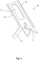
- Fig. 3 shows a further embodiment of the guide element 22 according to the invention, the shape of the guide slot 2 corresponding to the shape shown in Fig. 1 and 2 .
- the guide element 22 has lateral chamfers 16 which increase the stability of the guide element 22.
- a thread catcher 13 is shown in Fig. 3 , which protrudes laterally from the guide element 22 and around which a yarn end wraps due to its own rotation if a yarn break occurs during the spinning operation.
- Fig. 4 shows the guide element 22 shown in Fig. 3 together with a support 12 which can be connected via an attachment portion 18 to a corresponding holding structure of the workstation 23 of a ring spinning machine.
- the guide element 22 is attached to the support 12 by means of a screw 17 which passes through the recess 11 shown in Fig. 3 and which ensures fixing of the guide element 22 on the support 12 via a nut or a thread in the support 12.
- Fig. 5 shows the combination shown in Fig. 4 of the support 12 and the guide element 22 between a pair of output rollers 14 of a drafting system of a workstation 23 of a ring spinning machine and the yarn spinning unit 15 thereof, which has, inter alia, a bearing (not shown), for a cop 19 and a ring traveler unit 20, by means of which the twist is introduced into the fiber structure 1 coming from the drafting system, so that in the region of the guide element 22 a yarn 24 is produced with a twist, which yarn is finally wound onto the cop 19 by rotating said cop.
- the holding structure to which the support 12 is attached is not shown for reasons of clarity.
- the principle of ring spinning is also not discussed in more detail at this point, since this is well known from the prior art.
- a corresponding pivoting can take place manually or by means of a piecing robot in order to pivot the guide element 22 from the dashed position to the position shown by solid lines and thus to move the guide element 22 against the fiber structure 1 in order to insert the fiber structure 1 into the guide slot 2.
- FIG. 6a, 6b and 7a further forms of conceivable guide slots 2 not according to the invention are shown in Fig. 6a, 6b and 7a , the guide element 22 in each case being shown only in portions.
- the guide element 22 shown in Fig. 7b also has an alternative shape of the guide slot 2, in which in particular the end region 6 is formed by two regions (both provided with the reference number 6) which are opposite with respect to the transition region 5.
- the guide slot 2 in each case has an inlet opening 3, an adjoining inlet region 4, a transition region 5 adjoining the inlet region 4 and an end region 6 that completes the guide slot 2.
- the transition region 5 also has at least one change in direction according to the invention.
- Fig. 8 schematically shows a section of the guide element 22 of Fig. 1 .
- the drop-shaped end region 6 has a circular arcuate wall portion 9 which has in the plan view as shown a radius (Rc) of between 1.75 mm and 2.0 mm.
- Rc radius
- this allows a fiber strand (not shown in Fig. 8 ) to align itself thermodynamically optimally at different points along the circular arcuate wall portion 9, as shown in Fig. 9a .
- a typical path of motion (represented by the arrow with the broken line) of a fiber strand 1 relatively to the walls that delimitate the end region 6 of the guide slot 2 during ring spinning using a variation of a guide element 22 according to the present invention is schematically shown.
- the end region 6 of the guide slot 2 has a circular arcuate wall portion 9 having a radius (see. Fig. 8 ) about 1.75 mm. This causes the fiber strand 1 during the ring spinning process to move along the circular arcuate wall portion 9. This is because the fiber strand automatically aligns itself optimally in terms of energy due to thermodynamic principles.
- the fiber strand in many cases performs a kind of periodic movement roughly in the form of the large Latin letter D, as schematically illustrated.
- This periodic movement is only minor and results in a quasi-stationary guidance of the fiber strand. If such a quasi-stationary spinning process is disturbed, e.g. due to a thick spot in the supplied roving, the suddenly occurring different conditions can lead to a destabilization of this guidance. In many cases this effects a chaotic and highly dynamic movement of the fiber strand 1 away from the circular arcuate wall portion 9, as indicated in Fig. 9b by the arrow with the broken line.
- the fiber strand 1 may move further away from the circular arcuate wall portion 9 towards the pointed end of the drop shaped end region 6 of the guide slot 2.
- the fiber strand 1 will be confined and decelerated by the tapering side walls 7 restrict its movement more and more.
- the fiber strand 1 becomes increasingly confined and decelerated (calmed) by the geometrical constrains given by the tapering side walls 7.
- the increasing constriction of the fiber strand 1 by the side walls 7 causes a stabilization of the fiber strand 1, which finally returns to the circular arcuate wall portion 9 at the blunt side of the drop-like form.
Landscapes
- Engineering & Computer Science (AREA)
- Mechanical Engineering (AREA)
- Textile Engineering (AREA)
- Spinning Or Twisting Of Yarns (AREA)
Claims (14)
- Élément de guidage (22) pour une structure de fibre de type brin (1) pour un métier à filer continu à anneaux, ayant une fente de guidage (2),- la fente de guidage (2) ayant une ouverture d'entrée (3) avec une région d'entrée (4) attenant à l'ouverture d'entrée (3) et se rétrécissant en forme d'entonnoir à partir de l'ouverture d'entrée (3),- la fente de guidage (2) ayant une région de transition (5) reliée à la région d'entrée (4) sur une extrémité de la région d'entrée (4) éloignée de l'ouverture d'entrée (3),- la fente de guidage (2) ayant une région d'extrémité (6) disposée sur une extrémité de la région de transition (5) orientée à l'écart de la région d'entrée (4) et délimite la fente de guidage (2) dans une direction orientée à l'écart de l'ouverture d'entrée (3),la fente de guidage (2) ayant au moins un changement de direction dans la région de transition (5), caractérisé en ce que la région de transition (5) a, de chaque côté opposé de la fente de guidage (2), au moins une partie de retenue (10) pour la structure de fibre (1).
- Élément de guidage (22) selon la revendication précédente,
caractérisé en ce que l'élément de guidage (22) a deux parois latérales (7) délimitant la région d'entrée (4) et couvrant un angle (α), dont la valeur est comprise entre 50° et 90°, de préférence entre 60° et 80°. - Élément de guidage (22) selon l'une des revendications précédentes,
caractérisé en ce que l'élément de guidage (22) a, dans la région de transition (5), deux parois latérales (7) couvrant un angle (β), lesquelles parois latérales sont à proximité l'une de l'autre et délimitent la fente de guidage (2), l'angle (β) ayant une valeur comprise entre 30° et 150°, de préférence entre 60° et 120°. - Élément de guidage (22) selon la revendication 3, caractérisé en ce qu'une des parois latérales (7) de la région de transition (5) est à proximité d'une paroi latérale (7) de la région d'extrémité (6) s'étendant vers le côté de la région d'extrémité orientée à l'écart de l'ouverture d'entrée dans une vue en plan de l'élément de guidage, la paroi latérale de la région de transition (5) formant un angle (γ) avec ladite paroi latérale de la région d'extrémité (6), la valeur duquel angle est comprise entre 60° et 150°, de préférence entre 80° et 130°.
- Élément de guidage (22) selon l'une quelconque des revendications précédentes, caractérisé en ce que la largeur libre (8) de la fente de guidage dans la région de transition (5) s'élargit au moins une fois et se rétrécit ensuite une fois.
- Élément de guidage (22) selon l'une quelconque des revendications précédentes, caractérisé en ce que la fente de guidage (2) a, dans la région de transition (5), une largeur libre (8) dont la valeur varie entre 0,5 mm et 7,0 mm, de préférence entre 0,7 mm et 5,0 mm, au cours de la région de transition (5).
- Élément de guidage (22) selon l'une quelconque des revendications précédentes, caractérisé en ce que la région d'entrée (4) a, dans la région de l'ouverture d'entrée (3), une largeur libre (8) dont la valeur est comprise entre 5 mm et 20 mm, de préférence entre 12 mm et 17 mm.
- Élément de guidage (22) selon la revendication précédente,
caractérisé en ce que la largeur libre (8) de la fente de guidage depuis l'ouverture d'entrée (3) jusqu'à l'extrémité de la région d'entrée (4) qui est éloignée de l'ouverture d'entrée (3) est réduite à une valeur comprise entre 0,5 mm et 3,0 mm, de préférence entre 0,7 mm et 1,5 mm. - Élément de guidage (22) selon l'une quelconque des revendications précédentes, caractérisé en ce que la région d'extrémité (6) a une partie de paroi arquée (9) sur un côté éloigné de l'ouverture d'entrée (3).
- Élément de guidage (22) selon l'une quelconque des revendications précédentes, caractérisé en ce que la région d'extrémité (6) de la fente de guidage (2) est en forme de goutte.
- Élément de guidage (22) selon l'une quelconque des revendications précédentes, caractérisé en ce qu'au moins l'une parmi les parties de retenue (10) est formée par un renflement en forme de crochet.
- Élément de guidage (22) selon la revendication 11, caractérisé en ce que les parties de retenue (10) sont disposées l'une derrière l'autre dans une direction s'étendant depuis l'ouverture d'entrée (3) vers la région d'extrémité.
- Élément de guidage (22) selon l'une quelconque des revendications précédentes, caractérisé en ce que l'élément de guidage (22) a un évidement (11) qui n'est pas relié à la fente de guidage (2), l'évidement (11) étant utilisé pour fixer l'élément de guidage (22) à un support d'une station de travail (23) d'un métier à filer continu à anneaux.
- Métier à filer continu à anneaux ayant au moins une station de travail (23) pour produire un fil (24), la station de travail (23) ayant un élément de guidage (22) pour guider une structure de fibre de type brin (1) s'étendant entre un système d'étirage et une unité d'enroulement de fil de la station de travail (23),
caractérisé en ce que l'élément de guidage (22) est conçu selon une ou plusieurs des revendications précédentes.
Applications Claiming Priority (1)
| Application Number | Priority Date | Filing Date | Title |
|---|---|---|---|
| CH01664/20A CH718214A1 (de) | 2020-12-23 | 2020-12-23 | Führungselement sowie damit ausgestattete Arbeitsstelle einer Ringspinnmaschine. |
Publications (3)
| Publication Number | Publication Date |
|---|---|
| EP4023799A1 EP4023799A1 (fr) | 2022-07-06 |
| EP4023799B1 true EP4023799B1 (fr) | 2024-08-14 |
| EP4023799B8 EP4023799B8 (fr) | 2024-09-25 |
Family
ID=81828061
Family Applications (1)
| Application Number | Title | Priority Date | Filing Date |
|---|---|---|---|
| EP21214473.7A Active EP4023799B8 (fr) | 2020-12-23 | 2021-12-14 | Élément de guidage pour une machine à filer à anneaux et station de travail équipée de celui-ci et machine à filer à anneaux |
Country Status (4)
| Country | Link |
|---|---|
| EP (1) | EP4023799B8 (fr) |
| CN (1) | CN114657664A (fr) |
| CH (1) | CH718214A1 (fr) |
| ES (1) | ES2995970T3 (fr) |
Families Citing this family (3)
| Publication number | Priority date | Publication date | Assignee | Title |
|---|---|---|---|---|
| CH720604A1 (de) * | 2023-03-13 | 2024-09-30 | Rieter Ag Maschf | Fadenführeranordnung sowie damit ausgestattete ringspinnmaschine |
| CH721808A1 (de) | 2024-05-08 | 2025-11-14 | Rieter Ag Maschf | Handhabungsvorrichtung für eine wartungseinrichtung zur reinigung von fadenführungselementen sowie ein reinigungsverfahren |
| CN119877156B (zh) * | 2024-12-31 | 2026-04-07 | 东嘉麻棉(常州)有限公司 | 一种牵伸均匀的细纱机调控牵伸机构 |
Family Cites Families (12)
| Publication number | Priority date | Publication date | Assignee | Title |
|---|---|---|---|---|
| GB191003261A (en) * | 1910-02-10 | 1910-10-13 | Norman Seddon Brown | Improvements in Thread Guides or Lappets for Spinning and Doubling Frames. |
| GB191107367A (en) * | 1911-03-24 | 1912-03-25 | John Ernest Tytler | Improvements in or in connection with Lappets or Thread-guiding Devices for Spinning and other Machines. |
| US4509702A (en) * | 1983-01-27 | 1985-04-09 | Ppg Industries, Inc. | Apparatus for packaging a plurality of fibers or strands |
| CH685508A5 (de) * | 1992-06-03 | 1995-07-31 | Gegauf Fritz Ag | Spulenkapsel mit Fadenspannvorrichtung. |
| CZ16402U1 (cs) * | 2005-12-20 | 2006-04-03 | Rieter Cz A. S. | Zařízení k vedení příze nebo jiného lineárního textilního materiálu |
| DE102008057321A1 (de) * | 2008-11-14 | 2010-05-20 | Oerlikon Textile Gmbh & Co. Kg | Arbeitsstelle einer Spulmaschine mit einem saugluftbeaufschlagten Greiferrohr |
| CN103469392B (zh) * | 2013-09-10 | 2015-09-02 | 江南大学 | 一种导纱钩装置 |
| CN203513882U (zh) * | 2013-09-10 | 2014-04-02 | 江南大学 | 一种导纱钩装置 |
| CN203903656U (zh) * | 2013-09-22 | 2014-10-29 | 青岛宏大纺织机械有限责任公司 | 自动络筒机张力导纱装置及自动络筒机 |
| CN104630947A (zh) * | 2013-11-12 | 2015-05-20 | 沈旭超 | 多孔导纱器 |
| CN204079093U (zh) * | 2014-08-19 | 2015-01-07 | 丁宏利 | 通用型自络导纱板 |
| CZ201850A3 (cs) * | 2018-01-31 | 2019-06-26 | Rieter Cz S.R.O. | Vodič příze pro spřádací místo prstencového spřádacího stroje, prstencový spřádací stroj a způsob navlékání příze do vodiče příze |
-
2020
- 2020-12-23 CH CH01664/20A patent/CH718214A1/de not_active Application Discontinuation
-
2021
- 2021-12-14 EP EP21214473.7A patent/EP4023799B8/fr active Active
- 2021-12-14 ES ES21214473T patent/ES2995970T3/es active Active
- 2021-12-22 CN CN202111579425.9A patent/CN114657664A/zh active Pending
Also Published As
| Publication number | Publication date |
|---|---|
| ES2995970T3 (en) | 2025-02-11 |
| EP4023799B8 (fr) | 2024-09-25 |
| CH718214A1 (de) | 2022-06-30 |
| EP4023799A1 (fr) | 2022-07-06 |
| CN114657664A (zh) | 2022-06-24 |
Similar Documents
| Publication | Publication Date | Title |
|---|---|---|
| EP4023799B1 (fr) | Élément de guidage pour une machine à filer à anneaux et station de travail équipée de celui-ci et machine à filer à anneaux | |
| EP3950551B1 (fr) | Dispositif et méthode de contrôle d'un ballon, unité d'enroulement comportant un tel dispositif | |
| JPS6290330A (ja) | オ−プンエンド紡績用の紡績機 | |
| EP3012362A2 (fr) | Tige de guidage creuse, dispositif de filières à air et machinerie textile | |
| EP3124658B1 (fr) | Dispositif de dessin pour un cadre de filature | |
| US4543778A (en) | Textile spindle assembly and method | |
| US4202161A (en) | Apparatus for producing novelty yarn | |
| EP3115489B1 (fr) | Dispositif d'arrêt d'alimentation de faisceau de fibres pour métier à tisser | |
| US20170152124A1 (en) | Textile Machine for the Production of Roving and Method for Operating the Same | |
| CN108069289B (zh) | 用于机械纱线蓄能器的纱线偏转辊 | |
| GB2182069A (en) | Draw-off nozzle for roving and spinning frames | |
| EP0303063A1 (fr) | Système de filature ayant un dispositif rotatif pour contrôler le ballon du fil | |
| US3823539A (en) | Yarn spinning apparatus | |
| CN1213932C (zh) | 一种片状染色分纱工艺 | |
| JPH0157027B2 (fr) | ||
| CN209242324U (zh) | 工字轮固定装置 | |
| US2428288A (en) | Guide-mounting arrangement | |
| US1962693A (en) | Flier block construction | |
| CN213596501U (zh) | 一种纤维退丝装置 | |
| US158295A (en) | Improvement in stopping mechanisms for doubling-machines | |
| US829467A (en) | Traverse-guide for doubling and twisting machines. | |
| US4433538A (en) | Textile spinning machines | |
| EP0496114B1 (fr) | Procédé pour la filature continue de fibres discontinues et dispositif pour la mise en oeuvre de ce procédé | |
| JP7369795B2 (ja) | 糸を製造するためのリング紡績システム、およびリング紡績システムのドラフトステージへのフィラメントの供給を停止する方法 | |
| US739983A (en) | Spinning-machine. |
Legal Events
| Date | Code | Title | Description |
|---|---|---|---|
| PUAI | Public reference made under article 153(3) epc to a published international application that has entered the european phase |
Free format text: ORIGINAL CODE: 0009012 |
|
| STAA | Information on the status of an ep patent application or granted ep patent |
Free format text: STATUS: THE APPLICATION HAS BEEN PUBLISHED |
|
| AK | Designated contracting states |
Kind code of ref document: A1 Designated state(s): AL AT BE BG CH CY CZ DE DK EE ES FI FR GB GR HR HU IE IS IT LI LT LU LV MC MK MT NL NO PL PT RO RS SE SI SK SM TR |
|
| STAA | Information on the status of an ep patent application or granted ep patent |
Free format text: STATUS: REQUEST FOR EXAMINATION WAS MADE |
|
| 17P | Request for examination filed |
Effective date: 20221108 |
|
| RBV | Designated contracting states (corrected) |
Designated state(s): AL AT BE BG CH CY CZ DE DK EE ES FI FR GB GR HR HU IE IS IT LI LT LU LV MC MK MT NL NO PL PT RO RS SE SI SK SM TR |
|
| P01 | Opt-out of the competence of the unified patent court (upc) registered |
Effective date: 20230519 |
|
| GRAP | Despatch of communication of intention to grant a patent |
Free format text: ORIGINAL CODE: EPIDOSNIGR1 |
|
| STAA | Information on the status of an ep patent application or granted ep patent |
Free format text: STATUS: GRANT OF PATENT IS INTENDED |
|
| INTG | Intention to grant announced |
Effective date: 20240313 |
|
| GRAS | Grant fee paid |
Free format text: ORIGINAL CODE: EPIDOSNIGR3 |
|
| GRAA | (expected) grant |
Free format text: ORIGINAL CODE: 0009210 |
|
| STAA | Information on the status of an ep patent application or granted ep patent |
Free format text: STATUS: THE PATENT HAS BEEN GRANTED |
|
| REG | Reference to a national code |
Ref country code: DE Ref legal event code: R081 Ref document number: 602021017153 Country of ref document: DE Owner name: RIETER AG, CH Free format text: FORMER OWNER: MASCHINENFABRIK RIETER AG, WINTERTHUR, CH |
|
| AK | Designated contracting states |
Kind code of ref document: B1 Designated state(s): AL AT BE BG CH CY CZ DE DK EE ES FI FR GB GR HR HU IE IS IT LI LT LU LV MC MK MT NL NO PL PT RO RS SE SI SK SM TR |
|
| REG | Reference to a national code |
Ref country code: GB Ref legal event code: FG4D |
|
| REG | Reference to a national code |
Ref country code: CH Ref legal event code: EP |
|
| RAP4 | Party data changed (patent owner data changed or rights of a patent transferred) |
Owner name: RIETER AG |
|
| REG | Reference to a national code |
Ref country code: DE Ref legal event code: R096 Ref document number: 602021017153 Country of ref document: DE |
|
| REG | Reference to a national code |
Ref country code: CH Ref legal event code: PK Free format text: BERICHTIGUNG B8 |
|
| REG | Reference to a national code |
Ref country code: IE Ref legal event code: FG4D |
|
| REG | Reference to a national code |
Ref country code: LT Ref legal event code: MG9D |
|
| REG | Reference to a national code |
Ref country code: NL Ref legal event code: MP Effective date: 20240814 |
|
| PG25 | Lapsed in a contracting state [announced via postgrant information from national office to epo] |
Ref country code: NO Free format text: LAPSE BECAUSE OF FAILURE TO SUBMIT A TRANSLATION OF THE DESCRIPTION OR TO PAY THE FEE WITHIN THE PRESCRIBED TIME-LIMIT Effective date: 20241114 |
|
| REG | Reference to a national code |
Ref country code: AT Ref legal event code: MK05 Ref document number: 1713371 Country of ref document: AT Kind code of ref document: T Effective date: 20240814 |
|
| PG25 | Lapsed in a contracting state [announced via postgrant information from national office to epo] |
Ref country code: NL Free format text: LAPSE BECAUSE OF FAILURE TO SUBMIT A TRANSLATION OF THE DESCRIPTION OR TO PAY THE FEE WITHIN THE PRESCRIBED TIME-LIMIT Effective date: 20240814 Ref country code: PT Free format text: LAPSE BECAUSE OF FAILURE TO SUBMIT A TRANSLATION OF THE DESCRIPTION OR TO PAY THE FEE WITHIN THE PRESCRIBED TIME-LIMIT Effective date: 20241216 Ref country code: PL Free format text: LAPSE BECAUSE OF FAILURE TO SUBMIT A TRANSLATION OF THE DESCRIPTION OR TO PAY THE FEE WITHIN THE PRESCRIBED TIME-LIMIT Effective date: 20240814 Ref country code: GR Free format text: LAPSE BECAUSE OF FAILURE TO SUBMIT A TRANSLATION OF THE DESCRIPTION OR TO PAY THE FEE WITHIN THE PRESCRIBED TIME-LIMIT Effective date: 20241115 Ref country code: FI Free format text: LAPSE BECAUSE OF FAILURE TO SUBMIT A TRANSLATION OF THE DESCRIPTION OR TO PAY THE FEE WITHIN THE PRESCRIBED TIME-LIMIT Effective date: 20240814 |
|
| PG25 | Lapsed in a contracting state [announced via postgrant information from national office to epo] |
Ref country code: BG Free format text: LAPSE BECAUSE OF FAILURE TO SUBMIT A TRANSLATION OF THE DESCRIPTION OR TO PAY THE FEE WITHIN THE PRESCRIBED TIME-LIMIT Effective date: 20240814 |
|
| PG25 | Lapsed in a contracting state [announced via postgrant information from national office to epo] |
Ref country code: LV Free format text: LAPSE BECAUSE OF FAILURE TO SUBMIT A TRANSLATION OF THE DESCRIPTION OR TO PAY THE FEE WITHIN THE PRESCRIBED TIME-LIMIT Effective date: 20240814 |
|
| PG25 | Lapsed in a contracting state [announced via postgrant information from national office to epo] |
Ref country code: AT Free format text: LAPSE BECAUSE OF FAILURE TO SUBMIT A TRANSLATION OF THE DESCRIPTION OR TO PAY THE FEE WITHIN THE PRESCRIBED TIME-LIMIT Effective date: 20240814 Ref country code: IS Free format text: LAPSE BECAUSE OF FAILURE TO SUBMIT A TRANSLATION OF THE DESCRIPTION OR TO PAY THE FEE WITHIN THE PRESCRIBED TIME-LIMIT Effective date: 20241214 |
|
| PG25 | Lapsed in a contracting state [announced via postgrant information from national office to epo] |
Ref country code: HR Free format text: LAPSE BECAUSE OF FAILURE TO SUBMIT A TRANSLATION OF THE DESCRIPTION OR TO PAY THE FEE WITHIN THE PRESCRIBED TIME-LIMIT Effective date: 20240814 |
|
| PG25 | Lapsed in a contracting state [announced via postgrant information from national office to epo] |
Ref country code: RS Free format text: LAPSE BECAUSE OF FAILURE TO SUBMIT A TRANSLATION OF THE DESCRIPTION OR TO PAY THE FEE WITHIN THE PRESCRIBED TIME-LIMIT Effective date: 20241114 |
|
| PG25 | Lapsed in a contracting state [announced via postgrant information from national office to epo] |
Ref country code: RS Free format text: LAPSE BECAUSE OF FAILURE TO SUBMIT A TRANSLATION OF THE DESCRIPTION OR TO PAY THE FEE WITHIN THE PRESCRIBED TIME-LIMIT Effective date: 20241114 Ref country code: PT Free format text: LAPSE BECAUSE OF FAILURE TO SUBMIT A TRANSLATION OF THE DESCRIPTION OR TO PAY THE FEE WITHIN THE PRESCRIBED TIME-LIMIT Effective date: 20241216 Ref country code: PL Free format text: LAPSE BECAUSE OF FAILURE TO SUBMIT A TRANSLATION OF THE DESCRIPTION OR TO PAY THE FEE WITHIN THE PRESCRIBED TIME-LIMIT Effective date: 20240814 Ref country code: NO Free format text: LAPSE BECAUSE OF FAILURE TO SUBMIT A TRANSLATION OF THE DESCRIPTION OR TO PAY THE FEE WITHIN THE PRESCRIBED TIME-LIMIT Effective date: 20241114 Ref country code: NL Free format text: LAPSE BECAUSE OF FAILURE TO SUBMIT A TRANSLATION OF THE DESCRIPTION OR TO PAY THE FEE WITHIN THE PRESCRIBED TIME-LIMIT Effective date: 20240814 Ref country code: LV Free format text: LAPSE BECAUSE OF FAILURE TO SUBMIT A TRANSLATION OF THE DESCRIPTION OR TO PAY THE FEE WITHIN THE PRESCRIBED TIME-LIMIT Effective date: 20240814 Ref country code: IS Free format text: LAPSE BECAUSE OF FAILURE TO SUBMIT A TRANSLATION OF THE DESCRIPTION OR TO PAY THE FEE WITHIN THE PRESCRIBED TIME-LIMIT Effective date: 20241214 Ref country code: HR Free format text: LAPSE BECAUSE OF FAILURE TO SUBMIT A TRANSLATION OF THE DESCRIPTION OR TO PAY THE FEE WITHIN THE PRESCRIBED TIME-LIMIT Effective date: 20240814 Ref country code: GR Free format text: LAPSE BECAUSE OF FAILURE TO SUBMIT A TRANSLATION OF THE DESCRIPTION OR TO PAY THE FEE WITHIN THE PRESCRIBED TIME-LIMIT Effective date: 20241115 Ref country code: FI Free format text: LAPSE BECAUSE OF FAILURE TO SUBMIT A TRANSLATION OF THE DESCRIPTION OR TO PAY THE FEE WITHIN THE PRESCRIBED TIME-LIMIT Effective date: 20240814 Ref country code: BG Free format text: LAPSE BECAUSE OF FAILURE TO SUBMIT A TRANSLATION OF THE DESCRIPTION OR TO PAY THE FEE WITHIN THE PRESCRIBED TIME-LIMIT Effective date: 20240814 Ref country code: AT Free format text: LAPSE BECAUSE OF FAILURE TO SUBMIT A TRANSLATION OF THE DESCRIPTION OR TO PAY THE FEE WITHIN THE PRESCRIBED TIME-LIMIT Effective date: 20240814 |
|
| REG | Reference to a national code |
Ref country code: ES Ref legal event code: FG2A Ref document number: 2995970 Country of ref document: ES Kind code of ref document: T3 Effective date: 20250211 |
|
| PG25 | Lapsed in a contracting state [announced via postgrant information from national office to epo] |
Ref country code: SM Free format text: LAPSE BECAUSE OF FAILURE TO SUBMIT A TRANSLATION OF THE DESCRIPTION OR TO PAY THE FEE WITHIN THE PRESCRIBED TIME-LIMIT Effective date: 20240814 Ref country code: RO Free format text: LAPSE BECAUSE OF FAILURE TO SUBMIT A TRANSLATION OF THE DESCRIPTION OR TO PAY THE FEE WITHIN THE PRESCRIBED TIME-LIMIT Effective date: 20240814 Ref country code: DK Free format text: LAPSE BECAUSE OF FAILURE TO SUBMIT A TRANSLATION OF THE DESCRIPTION OR TO PAY THE FEE WITHIN THE PRESCRIBED TIME-LIMIT Effective date: 20240814 |
|
| PG25 | Lapsed in a contracting state [announced via postgrant information from national office to epo] |
Ref country code: CZ Free format text: LAPSE BECAUSE OF FAILURE TO SUBMIT A TRANSLATION OF THE DESCRIPTION OR TO PAY THE FEE WITHIN THE PRESCRIBED TIME-LIMIT Effective date: 20240814 |
|
| PG25 | Lapsed in a contracting state [announced via postgrant information from national office to epo] |
Ref country code: IT Free format text: LAPSE BECAUSE OF FAILURE TO SUBMIT A TRANSLATION OF THE DESCRIPTION OR TO PAY THE FEE WITHIN THE PRESCRIBED TIME-LIMIT Effective date: 20240814 Ref country code: SK Free format text: LAPSE BECAUSE OF FAILURE TO SUBMIT A TRANSLATION OF THE DESCRIPTION OR TO PAY THE FEE WITHIN THE PRESCRIBED TIME-LIMIT Effective date: 20240814 |
|
| REG | Reference to a national code |
Ref country code: DE Ref legal event code: R097 Ref document number: 602021017153 Country of ref document: DE |
|
| PLBE | No opposition filed within time limit |
Free format text: ORIGINAL CODE: 0009261 |
|
| STAA | Information on the status of an ep patent application or granted ep patent |
Free format text: STATUS: NO OPPOSITION FILED WITHIN TIME LIMIT |
|
| PG25 | Lapsed in a contracting state [announced via postgrant information from national office to epo] |
Ref country code: MC Free format text: LAPSE BECAUSE OF FAILURE TO SUBMIT A TRANSLATION OF THE DESCRIPTION OR TO PAY THE FEE WITHIN THE PRESCRIBED TIME-LIMIT Effective date: 20240814 |
|
| 26N | No opposition filed |
Effective date: 20250515 |
|
| REG | Reference to a national code |
Ref country code: CH Ref legal event code: PL |
|
| PG25 | Lapsed in a contracting state [announced via postgrant information from national office to epo] |
Ref country code: LU Free format text: LAPSE BECAUSE OF NON-PAYMENT OF DUE FEES Effective date: 20241214 |
|
| PG25 | Lapsed in a contracting state [announced via postgrant information from national office to epo] |
Ref country code: SE Free format text: LAPSE BECAUSE OF FAILURE TO SUBMIT A TRANSLATION OF THE DESCRIPTION OR TO PAY THE FEE WITHIN THE PRESCRIBED TIME-LIMIT Effective date: 20240814 |
|
| REG | Reference to a national code |
Ref country code: BE Ref legal event code: MM Effective date: 20241231 |
|
| PG25 | Lapsed in a contracting state [announced via postgrant information from national office to epo] |
Ref country code: BE Free format text: LAPSE BECAUSE OF NON-PAYMENT OF DUE FEES Effective date: 20241231 |
|
| PG25 | Lapsed in a contracting state [announced via postgrant information from national office to epo] |
Ref country code: FR Free format text: LAPSE BECAUSE OF NON-PAYMENT OF DUE FEES Effective date: 20241231 |
|
| PG25 | Lapsed in a contracting state [announced via postgrant information from national office to epo] |
Ref country code: CH Free format text: LAPSE BECAUSE OF NON-PAYMENT OF DUE FEES Effective date: 20241231 |
|
| PG25 | Lapsed in a contracting state [announced via postgrant information from national office to epo] |
Ref country code: IE Free format text: LAPSE BECAUSE OF NON-PAYMENT OF DUE FEES Effective date: 20241214 |
|
| PGFP | Annual fee paid to national office [announced via postgrant information from national office to epo] |
Ref country code: TR Payment date: 20251209 Year of fee payment: 5 |
|
| PGFP | Annual fee paid to national office [announced via postgrant information from national office to epo] |
Ref country code: ES Payment date: 20260119 Year of fee payment: 5 |
|
| PGFP | Annual fee paid to national office [announced via postgrant information from national office to epo] |
Ref country code: DE Payment date: 20251222 Year of fee payment: 5 |