EP4040027B1 - Schlauchklemme mit einem halteelement und einem haken - Google Patents
Schlauchklemme mit einem halteelement und einem haken Download PDFInfo
- Publication number
- EP4040027B1 EP4040027B1 EP22155289.6A EP22155289A EP4040027B1 EP 4040027 B1 EP4040027 B1 EP 4040027B1 EP 22155289 A EP22155289 A EP 22155289A EP 4040027 B1 EP4040027 B1 EP 4040027B1
- Authority
- EP
- European Patent Office
- Prior art keywords
- hook
- belt
- retaining member
- abutment
- clamping collar
- Prior art date
- Legal status (The legal status is an assumption and is not a legal conclusion. Google has not performed a legal analysis and makes no representation as to the accuracy of the status listed.)
- Active
Links
Images


Classifications
-
- F—MECHANICAL ENGINEERING; LIGHTING; HEATING; WEAPONS; BLASTING
- F16—ENGINEERING ELEMENTS AND UNITS; GENERAL MEASURES FOR PRODUCING AND MAINTAINING EFFECTIVE FUNCTIONING OF MACHINES OR INSTALLATIONS; THERMAL INSULATION IN GENERAL
- F16B—DEVICES FOR FASTENING OR SECURING CONSTRUCTIONAL ELEMENTS OR MACHINE PARTS TOGETHER, e.g. NAILS, BOLTS, CIRCLIPS, CLAMPS, CLIPS OR WEDGES; JOINTS OR JOINTING
- F16B2/00—Friction-grip releasable fastenings
- F16B2/02—Clamps, i.e. with gripping action effected by positive means other than the inherent resistance to deformation of the material of the fastening
- F16B2/06—Clamps, i.e. with gripping action effected by positive means other than the inherent resistance to deformation of the material of the fastening external, i.e. with contracting action
- F16B2/08—Clamps, i.e. with gripping action effected by positive means other than the inherent resistance to deformation of the material of the fastening external, i.e. with contracting action using bands
-
- F—MECHANICAL ENGINEERING; LIGHTING; HEATING; WEAPONS; BLASTING
- F16—ENGINEERING ELEMENTS AND UNITS; GENERAL MEASURES FOR PRODUCING AND MAINTAINING EFFECTIVE FUNCTIONING OF MACHINES OR INSTALLATIONS; THERMAL INSULATION IN GENERAL
- F16L—PIPES; JOINTS OR FITTINGS FOR PIPES; SUPPORTS FOR PIPES, CABLES OR PROTECTIVE TUBING; MEANS FOR THERMAL INSULATION IN GENERAL
- F16L23/00—Flanged joints
- F16L23/04—Flanged joints the flanges being connected by members tensioned in the radial plane
-
- F—MECHANICAL ENGINEERING; LIGHTING; HEATING; WEAPONS; BLASTING
- F16—ENGINEERING ELEMENTS AND UNITS; GENERAL MEASURES FOR PRODUCING AND MAINTAINING EFFECTIVE FUNCTIONING OF MACHINES OR INSTALLATIONS; THERMAL INSULATION IN GENERAL
- F16L—PIPES; JOINTS OR FITTINGS FOR PIPES; SUPPORTS FOR PIPES, CABLES OR PROTECTIVE TUBING; MEANS FOR THERMAL INSULATION IN GENERAL
- F16L23/00—Flanged joints
- F16L23/02—Flanged joints the flanges being connected by members tensioned axially
- F16L23/036—Flanged joints the flanges being connected by members tensioned axially characterised by the tensioning members, e.g. specially adapted bolts or C-clamps
-
- F—MECHANICAL ENGINEERING; LIGHTING; HEATING; WEAPONS; BLASTING
- F16—ENGINEERING ELEMENTS AND UNITS; GENERAL MEASURES FOR PRODUCING AND MAINTAINING EFFECTIVE FUNCTIONING OF MACHINES OR INSTALLATIONS; THERMAL INSULATION IN GENERAL
- F16L—PIPES; JOINTS OR FITTINGS FOR PIPES; SUPPORTS FOR PIPES, CABLES OR PROTECTIVE TUBING; MEANS FOR THERMAL INSULATION IN GENERAL
- F16L33/00—Arrangements for connecting hoses to rigid members; Rigid hose-connectors, i.e. single members engaging both hoses
- F16L33/02—Hose-clips
- F16L33/023—Hose-clips fixed by bending one end of the strap
-
- F—MECHANICAL ENGINEERING; LIGHTING; HEATING; WEAPONS; BLASTING
- F16—ENGINEERING ELEMENTS AND UNITS; GENERAL MEASURES FOR PRODUCING AND MAINTAINING EFFECTIVE FUNCTIONING OF MACHINES OR INSTALLATIONS; THERMAL INSULATION IN GENERAL
- F16L—PIPES; JOINTS OR FITTINGS FOR PIPES; SUPPORTS FOR PIPES, CABLES OR PROTECTIVE TUBING; MEANS FOR THERMAL INSULATION IN GENERAL
- F16L33/00—Arrangements for connecting hoses to rigid members; Rigid hose-connectors, i.e. single members engaging both hoses
- F16L33/02—Hose-clips
- F16L33/035—Hose-clips fixed by means of teeth or hooks
Definitions
- the present disclosure relates to a hose clamp, in particular a hose clamp of the type comprising a belt carrying a retaining member and a hook configured to engage the retaining member to define a hooked tightening state of the clamp.
- Clamps of this type are well known, for example from patent applications EP 2 480 355 , EP 0 627 591 or even US 5,353,478 .
- the other object may be a tube made of a material such as metal, and the object connected to it is a pipe, which is fitted onto the tube.
- the clamped object is formed by the ends of two axially connected tubes.
- the tubes may be made of metal and have, at their ends, radially projecting bearing surfaces on the outer peripheries of the tubes, these bearing surfaces together forming a bulge when the tubes are abutted.
- the belt of the clamp may have a recess which receives this bulge.
- the tubes are abutted and the clamp is placed around their bearing surfaces so that these can be received in the recess.
- the bearing surfaces and the recess may be shaped so as to bring the bearing surfaces closer together when the belt is tightened.
- the recess of the collar may have a V- or U-shaped section with legs (forming sides of the belt) folded towards the axis of the belt and slightly inclined relative to a plane perpendicular to this axis, moving away from each other towards their free ends close to the axis, and the bearing surfaces of the tubes may be inclined in the same way, so that the reduction in the diameter of the belt due to the tightening of the collar brings the bearing surfaces closer to each other.
- clamps generally provide satisfactory results in many applications.
- closing the clamp may temporarily cause excessive tightening, which may adversely affect the performance of the clamp. This may be the case, for example, when the clamp is used to tighten a pipe made of a hard material such as rigid plastic or metal to a fitting, or when the tube is used to axially connect two metal tubes, particularly by tightening them by their metal bearing surfaces.
- the clamping force of the clamp on the clamped object is temporarily too intense, it may happen that certain parts of the clamp, in particular the hook, undergo plastic deformations, i.e. irreversible deformations, or that the clamped object undergoes plastic deformations or damage such as microcracks.
- the document FR2705410 attempts to provide a solution to this problem by providing that the retaining member is provided with a stop capable of coming into abutment with the internal face of the hook when the hook is hooked behind the retaining member.
- the hook is moved so that the front wall of the hook is advanced on the retaining member until it exceeds a retaining surface of the retaining member in order to be able to hook onto this surface, at the rear of the retaining member.
- the stops come into cooperation, in order to prevent the hook from advancing further.
- This solution can be effective, but it can be difficult to ensure a good quality and reliable abutment contact between the stop and the internal face of the hook.
- this contact can be unstable and the internal face of the hook can then act as a sliding ramp for the stop without actually retaining it.
- the abutment contact may tend to oppose the slight radial inward tilting of the hook which, once the front wall of the hook has passed the first abutment member, is necessary to retain the hook hooked behind the retaining member.
- this solution may impair the attachment of the hook to the retaining member.
- US5549906 discloses a clamping collar whose retaining member is provided with a stop capable of coming into contact with the internal face of the hook when the hook is hooked behind the retaining member.
- US5144726 And US 4750242 disclose clamps having a retaining member having an extension that bridges the hook from the inside, and having a free end in the form of a fork that cooperates with a boss projecting radially on the inside to form a continuous surface.
- US4299012 discloses a clamp having an inner end of the strip having a tab that penetrates grooves formed in the other strip portion to form a continuous surface.
- the present disclosure aims to remedy at least in part the aforementioned drawbacks by ensuring that the risks of over-tightening are avoided, or at least limited, in particular when attaching the hook to the retaining member, thereby substantially avoiding the drawbacks of the aforementioned solution.
- the disclosure relates to a clamp comprising a belt carrying a retaining member and a hook configured to hook onto the retaining member to define a hooked tightening state of the collar, the belt comprising at least one flank which extends radially inwards, the hook having a front wall and a running portion which connects the front wall to the belt.
- the retaining member carries a first stop member capable, when the hook is hooked onto the retaining member, of coming into abutment with a second stop member to define a maximum advanced position of the hook relative to the retaining member.
- the belt has at least one stop wall element which is formed in the flank and which has the second stop member, and this second stop member is located, towards the front in the direction of movement of the hook towards the retaining member, at most in the connection zone of the belt to the hook.
- first and second abutment members each have a first and a second abutment contact surface located on either side of a diametrical plane of the belt, perpendicular to the axis of the latter.
- the belt has a recess delimited by two flanks which extend radially inwards, the abutment wall element comprising two portions of abutment wall elements, respectively formed in each of these two flanks.
- said at least one flank is interrupted at the end of the belt which carries the hook so as to present an edge portion, and the second stop member is formed on the edge portion.
- the flank is interrupted by a fold or a cut.
- the retaining member has an extension which, in the hooked state, extends under the current part of the hook and which has the first stop member.
- the extension has a stiffening relief.
- the retaining member comprises an external radial projection.
- first and second stop members can thus be produced in an extremely simple manner while fulfilling their function of defining the maximum advanced position of the hook relative to the stop member. retained at the time of hooking the hook onto the retaining member and, more precisely, at the time when the front wall of the hook passes to the rear of the retaining member to hook onto the latter, without risk of sliding between the stop members and without impairing the tilting of the hook necessary for the hooking.
- the collar is in particular made of metal, possibly in a single piece, and the first and second stop members can be made by simple bending, cutting and/or stamping in the metal material of the collar.
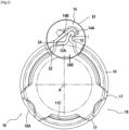
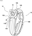
- FIG 1 shows a clamp 1 comprising a belt 10 having two ends, respectively 10A and 10B.
- the end 10A carries a retaining member 12, while the end 10B carries a hook 14 which is configured to hook onto the retaining member 12 to define a hooked state of tightening of the clamp shown in the figure 2 .
- the retaining member 12 projects radially outwardly relative to the outer periphery of the belt 10. In this case, it is a double fold formed outwardly.
- the belt 10 in the clamped state of the collar, the belt 10 defines a circle of axis A, this axis being defined as being the axis of the clamp collar or the axis of its belt.
- the outward or upward direction is defined as the direction away from this axis A.
- the inward or downward direction is the direction that moves closer to this axis A.
- the hook 14 is moved in the direction of the arrow F14.
- the forward direction will be considered to be that defined by this arrow F14.
- the forward direction is that which goes toward the retaining member 12 and the end 10A without passing through the belt.
- the retaining member 12 is moved toward the hook in the direction F12.
- the forward direction is defined as being that which goes towards the end 10B of the hook 14 without passing through the belt 10.
- the hook 14 has a front wall 14A and a running portion 14B which connects the front wall 14A to the belt 10. In the clamped state of the collar, the front wall 14A is retained behind the retaining member 12, while a front portion of the retaining member 12 is located under the running portion 14B of the hook 14.
- hook 14 is of the type described in French patent application no. FR 19 10485 in the name of the applicant, to which reference may be made.
- the running part 14B of the hook has a gripping surface 16 projecting radially outwards and two lateral edges 16A, 16B (see figure 3 ) which extend axially on either side of the gripping surface while being radially set back from them.
- axially is understood as being in the direction defined by the axis A.
- This gripping surface 16 is formed at the rear of a boss 16' of the running part 14B of the hook.
- the front wall 14A of the hook has at least one, in this case two, stiffening ribs 15.
- the current part 14B of the hook defines a substantially rectilinear general direction D, inclined at an angle ⁇ relative to the tangential direction T of the belt at the connection of the hook to the end 10B of the belt (see figure 1 ).
- This angle ⁇ is for example of the order of 10 to 40 degrees, in particular of the order of 20 to 30 degrees. It is noted that the current part of the hook is connected to the end 10B of the belt without folding, in particular without projection.
- the present disclosure may relate to other types of hooks, in particular a hook whose running part is defined by an outward radial undulation and/or whose connection zone at the end 10B of the belt is defined by an outward radial fold, for example as in the patent US 5,353,478 .
- the collar 1 during its tightening on an object 2 shown in a broken line.
- this object 2 is the assembly of two ends of tubes connected axially.
- the collar 1 is tightened using a tightening tool, in particular a clamp, of which we see two jaws respectively M1, which engages behind the retaining member 12 and M2, which engages on the hook 14, in this case behind its gripping surface 16.
- the retaining member 12 carries a first stop member 22 which, as can be seen in the figures 2 , 2A and 2B comes into abutment on a second stop member 24 when the hook 14 is hooked onto the retaining member 12 to define a maximum advanced position of the hook relative to the retaining member 12.
- FIG. 2 shows the collar just at the moment of attachment, when the front wall of the hook 14 passes behind the retaining member 12. While the stop members 22 and 24 are in abutment, a very slight space indicated by a clearance j may exist at the rear of the retaining member 12, between the rear wall of this retaining member 12 and the internal face of the front wall 14A of the hook. It is understood that the coming into abutment of the stop members 22 and 24 defines the maximum advanced position of the hook 14 relative to the retaining member 12.
- the first stop member is formed on an extension 12A of the retaining member 12 which extends forward relative to this retaining member 12 and which, in the hooked state, extends under the running part 14B of the hook.
- this extension 12A can be connected to the radially projecting part of the retaining member 12 by one or more stiffening elements, such as a work hardening 13 forming a recess on the inside and a boss on the outside.
- this work hardening forms a stiffening relief projecting either on the internal face or on the external face of the extension 12A.
- the retaining member 12 is formed in this case by a double radial fold with a rear fold portion 12' connected to the end 10A of the belt a front fold portion 12" which carries the extension 12A (see Figure 2B ).
- the stiffening relief 13 is formed at the junction between the front fold portion 12" and the extension 12A.
- the extension is offset radially inward relative to the top of the retaining member 12, extending for example substantially in the extension of the peripheral direction of the belt 10.
- the extension 12A can extend substantially in the circumferential direction of the belt, beyond the retaining member 12 going toward the front of this retaining member.
- the internal face of the extension 12A extends substantially circumferentially in the extension of the internal face of the belt. It is also possible for the extension to be substantially flat and to extend substantially tangentially to the circumferential direction of the belt, relative to the junction zone of the retaining member 12 at the end 10A of the belt.
- the second stop member 24 is located in the belt 10, in particular, in the connection zone of the end 10B of the belt to the hook 14. Thus, as can be seen in the Figure 2A , this second stop member 24 is located at the end 10B of the belt, in its transition zone with the current part 14B of the hook.
- the collar shown is of the type whose belt has a recess.
- this belt 10 has at least one flank 11A which extends inwards.
- the belt has two flanks, respectively 11A and 11C which extend on either side of a region 11B cylindrical power plant (see figure 3 ).
- the belt generally has a U-shaped or V-shaped radial section, with a vertex portion 11B, which forms the base of the U or the tip of the V and whose internal periphery defines the maximum internal diameter of the belt, and with two wings respectively defining two flanks 11A and 11C.
- This vertex portion 11B forms a central region, between the two flanks 11A and 11C.
- the object 2 clamped by the collar may have a radial bulge for example formed by the bearing surfaces of two axially connected tubes, received in the internal recess of the belt delimited between the flanks 11A and 11C.
- the extension 12A of the retaining member 12 extends in the extension of the periphery of the belt, it is in fact considered that it extends in the extension of the vertex portion 11B of the belt section.
- the flanks 11A and 11C are straightened radially to come substantially into the cylindrical surface defined by the central region 11B and form the retaining member 12 by folding.
- flanks 11A and 11C are straightened and it can be seen that the running part 14B of the hook is devoid of flanks, the continuity of the material of these then being located in the general circumferential direction defined by this running part 14B.
- the flanks 11A and 11C are interrupted and have edge portions oriented towards the front of the hook 14.
- the second stop member 24 is formed in these edge portions of the flanks 11A and 11C. These flanks form stop wall elements which, at the end 10B of the belt, form the second stop member 24. More precisely, the second stop member 24 is made in the edge portions of these flanks which form a transition zone between these flanks and the hook. Thus, in this case, the second stop member 24 is formed from the edge portions of the two flanks 11A and 11C which extend, in the connection zone of the hook at the end 10B of the belt, on either side of an axially median part of this connection zone.
- the second stop member comprises two parts, respectively located in the edge portions of each of the two sides 11A and 11C. More precisely, as seen in the Figures 2B and 2C , the first and second stop members 22 and 24 each have a first and a second stop contact surface Z1, Z2, which are located on either side of the diametrical median plane P of the belt, perpendicular to its axis 1. The collar is also symmetrical with respect to this plane P.
- the stop contact is distributed on either side of the plane P. It opposes tilting relative to this plane and therefore operates correctly, even if the clamping tool is imperfectly positioned relative to the hook and the retaining member.
- the second stop member Being formed in the flanks, which are areas in which the material is heavily work-hardened, the second stop member is particularly resistant to clamping forces.
- the collar has capacity reserves formed by zones 18 of the belt located between regions 17 in which the flanks 11A and 11C are locally interrupted.
- the zones 18 forming capacity reserve may have increased deformability, for example by having holes 18A or the like. From this point of view, the collar can be produced as described in French patent application no. 19 10486 , to which one can refer.
- the sides are interrupted at the end 10B of the belt by folds which straighten them in the plane of the central region 11B.
- flanks 11A and 11C are interrupted by cutouts.
- the edge portions in which the second stop member 124 is formed are the cutting edges of the flanks, which are oriented substantially radially.
- the collar is symmetrical with respect to the diametrical median plane P, which is perpendicular to the axis A of the belt, and the abutment contacts between the first and second stop members 22 and 124 are made on either side of the plane P.
- the hook may have a width (measured axially) which increases so that, in its front part 14A, the hook benefits from the full width of the strip in which the collar is formed. This is shown in particular by figure 5 . It can also be seen that, at the end 10A of the belt, the sides are brought into the same plane to form the retaining member, as in the previous embodiment. However, it would of course also be possible to interrupt the sides by cutting in this region.
- the second stop member is particularly resistant to clamping forces because it is formed on the edges of the cutouts, which are generally oriented radially and therefore offer clean and difficult to deform support surfaces. In addition, the positioning of the second stop member is particularly precise.
Landscapes
- Engineering & Computer Science (AREA)
- General Engineering & Computer Science (AREA)
- Mechanical Engineering (AREA)
- Clamps And Clips (AREA)
- Package Frames And Binding Bands (AREA)
- Hooks, Suction Cups, And Attachment By Adhesive Means (AREA)
- Flanged Joints, Insulating Joints, And Other Joints (AREA)
- Joints That Cut Off Fluids, And Hose Joints (AREA)
- Belt Conveyors (AREA)
Claims (8)
- Schlauchklemme (1), umfassend einen Riemen (10), der ein Halteelement (12) und einen Haken (14) trägt, der dazu ausgestaltet ist, sich auf dem Halteelement (12) einzuhaken, um einen Hakenspannzustand der Klemme zu definieren, wobei der Riemen (10) mindestens eine Flanke (11A, 11C) umfasst, die sich radial nach innen erstreckt, wobei der Haken (14) eine Vorderwand (14A) und einen Laufteil (14B) aufweist, der die Vorderwand mit dem Riemen (10) verbindet, wobei das Halteelement (12) ein erstes Anschlagselement (22) trägt, das ausgelegt ist, um beim Einhaken des Hakens auf dem Halteelement in Anschlag mit einem zweiten Anschlagselement (24, 34, 44) zu kommen, um eine maximal vorgeschobene Position des Hakens (14) in Bezug auf das Halteelement (12) zu definieren, dadurch gekennzeichnet, dass der Riemen (10) mindestens ein Anschlagwandelement (11A, 11C) aufweist, das in der Flanke (11A, 11C) gebildet ist und welches das zweite Anschlagselement (24) aufweist, und dass sich das zweite Anschlagselement nach vorne in der Bewegungsrichtung (F14) des Hakens zu dem Halteelement hin höchstens in dem Verbindungsbereich des Riemens (10) mit dem Haken (14) befindet.
- Schlauchklemme nach Anspruch 1, wobei das erste und das zweite Anschlagselement (22, 24) jeweils eine erste und eine zweite Anschlagkontaktfläche (Z1, Z2) aufweisen, die sich auf beiden Seiten einer Ebene (P) befinden, die diametral zu dem Riemen, senkrecht zu der Achse davon, verläuft.
- Schlauchklemme nach einem der Ansprüche 1 und 2, wobei der Riemen (10) eine Vertiefung aufweist, die durch zwei Flanken (11A, 11C) begrenzt ist, die sich radial nach innen erstrecken, wobei das Anschlagwandelement zwei Anschlagwandelementabschnitte umfasst, die jeweils in jeder dieser zwei Flanken gebildet sind.
- Schlauchklemme nach einem der Ansprüche 1 bis 3, wobei die mindestens eine Flanke (11A, 11C) an dem Ende (10B) des Riemens (10), der den Haken (14) trägt, unterbrochen ist, sodass sie einen Randabschnitt aufweist, und wobei das zweite Anschlagselement (24) auf dem Randabschnitt gebildet ist.
- Schlauchklemme nach Anspruch 4, wobei die Flanke (11A, 11C) durch eine Falte oder einen Schnitt unterbrochen ist.
- Schlauchklemme nach einem der Ansprüche 1 bis 5, wobei das Halteelement (12) eine Verlängerung (12A) aufweist, die sich in dem eingehakten Zustand unter dem Laufteil (14B) des Hakens (14) erstreckt und die das erste Anschlagselement (22) aufweist.
- Schlauchklemme nach Anspruch 6, wobei die Verlängerung (12A) ein Versteifungsrelief (13) aufweist.
- Schlauchklemme nach einem der Ansprüche 1 bis 7, wobei das Halteelement (12) einen externen radialen Vorsprung umfasst.
Applications Claiming Priority (1)
| Application Number | Priority Date | Filing Date | Title |
|---|---|---|---|
| FR2101217A FR3119650B1 (fr) | 2021-02-09 | 2021-02-09 | Collier de serrage ayant un organe de retenue et un crochet |
Publications (2)
| Publication Number | Publication Date |
|---|---|
| EP4040027A1 EP4040027A1 (de) | 2022-08-10 |
| EP4040027B1 true EP4040027B1 (de) | 2024-08-28 |
Family
ID=74860299
Family Applications (1)
| Application Number | Title | Priority Date | Filing Date |
|---|---|---|---|
| EP22155289.6A Active EP4040027B1 (de) | 2021-02-09 | 2022-02-04 | Schlauchklemme mit einem halteelement und einem haken |
Country Status (6)
| Country | Link |
|---|---|
| US (1) | US20220252192A1 (de) |
| EP (1) | EP4040027B1 (de) |
| JP (1) | JP2022122279A (de) |
| KR (1) | KR20220115075A (de) |
| CN (1) | CN114941643A (de) |
| FR (1) | FR3119650B1 (de) |
Families Citing this family (1)
| Publication number | Priority date | Publication date | Assignee | Title |
|---|---|---|---|---|
| FR3101127B1 (fr) * | 2019-09-23 | 2021-10-01 | Caillau | Collier de serrage |
Family Cites Families (23)
| Publication number | Priority date | Publication date | Assignee | Title |
|---|---|---|---|---|
| US2876514A (en) * | 1955-12-13 | 1959-03-10 | United Carr Fastener Corp | Hose clamp |
| US4299012A (en) * | 1979-05-08 | 1981-11-10 | Hans Oetiker | Hose clamp |
| FR2516181A1 (fr) * | 1981-11-06 | 1983-05-13 | Caillau Ets | Collier de serrage |
| FR2596468B1 (fr) * | 1986-03-27 | 1988-07-15 | Caillau Ets | Collier de serrage |
| US4821379A (en) * | 1988-03-31 | 1989-04-18 | Wittek Industries, Inc. | Self-aligning spring clamp |
| IT1217723B (it) * | 1988-05-26 | 1990-03-30 | Arcelli & Bernacchi | Fascetta metallica per giunzione di tubi |
| US4987652A (en) * | 1990-02-09 | 1991-01-29 | Spaulding George E | Spring clamp |
| FR2662488B1 (fr) * | 1990-05-23 | 1992-09-18 | Caillau Ets | Collier de serrage a reserve de capacite. |
| FR2670861B1 (fr) * | 1990-12-19 | 1993-04-16 | Caillau Ets | Collier de serrage elastique. |
| DE4237330C1 (de) | 1992-11-05 | 1993-10-28 | Rasmussen Gmbh | Schelle |
| FR2705410B1 (fr) * | 1993-05-19 | 1995-08-11 | Caillau Ets | Collier de serrage. |
| FR2705411B1 (fr) | 1993-05-19 | 1995-08-18 | Caillau Ets | Structure de collier de serrage. |
| FR2708708B1 (fr) * | 1993-07-30 | 1995-10-27 | Caillau Ets | Collier de serrage. |
| DE19650675C2 (de) * | 1996-12-06 | 2002-10-31 | Rasmussen Gmbh | Profilschelle |
| DE19750010C1 (de) * | 1997-11-12 | 1999-05-12 | Rasmussen Gmbh | Schelle |
| US5842450A (en) * | 1998-04-13 | 1998-12-01 | Ford Motor Company | Fuel regulator retaining clip |
| FR2818352B1 (fr) * | 2000-12-19 | 2003-04-18 | Caillau Ets | Collier de serrage |
| BRPI0604028B1 (pt) * | 2006-09-04 | 2019-12-24 | Embraco Ind De Compressores E Solucoes Em Refrigeracao Ltda | abraçadeira para conexões tubulares em pequenos sistemas de refrigeração |
| FR2950402B1 (fr) * | 2009-09-24 | 2011-10-21 | Caillau Ets | Collier de serrage. |
| FR2950403B1 (fr) | 2009-09-24 | 2011-10-21 | Caillau Ets | Collier de serrage et son procede de fabrication. |
| FR2967230B1 (fr) * | 2010-11-05 | 2013-08-30 | Caillau Ets | Collier de serrage articule |
| FR2989436B1 (fr) * | 2012-04-13 | 2015-02-13 | Caillau Ets | Collier de serrage |
| DE102013212629A1 (de) * | 2012-06-29 | 2014-01-02 | Behr Gmbh & Co. Kg | Verbindungselement |
-
2021
- 2021-02-09 FR FR2101217A patent/FR3119650B1/fr active Active
-
2022
- 2022-02-04 EP EP22155289.6A patent/EP4040027B1/de active Active
- 2022-02-08 CN CN202210117701.8A patent/CN114941643A/zh active Pending
- 2022-02-08 US US17/666,636 patent/US20220252192A1/en not_active Abandoned
- 2022-02-08 JP JP2022017629A patent/JP2022122279A/ja active Pending
- 2022-02-09 KR KR1020220016781A patent/KR20220115075A/ko active Pending
Also Published As
| Publication number | Publication date |
|---|---|
| FR3119650A1 (fr) | 2022-08-12 |
| EP4040027A1 (de) | 2022-08-10 |
| FR3119650B1 (fr) | 2023-04-14 |
| US20220252192A1 (en) | 2022-08-11 |
| JP2022122279A (ja) | 2022-08-22 |
| CN114941643A (zh) | 2022-08-26 |
| KR20220115075A (ko) | 2022-08-17 |
Similar Documents
| Publication | Publication Date | Title |
|---|---|---|
| EP2017518B1 (de) | Klemmvorrichtung mit Schlauchklemme und Positionierteil | |
| EP3217059B1 (de) | Spannanordnung mit einer spannschelle und einzelne vormontageclips | |
| EP2156088B1 (de) | Spannvorrichtung | |
| EP1451498B1 (de) | Spannvorrichtung zur dichten kupplung von zwei rohren mit spannauflagen | |
| EP2136120B1 (de) | Rohrschelle mit verformtem Rasthaken | |
| EP3189261B1 (de) | Kopplungssystem für zwei rohre | |
| EP2789888B1 (de) | Spannvorrichtung zum dichten Verbinden von Glattrohren | |
| FR3049997A1 (fr) | Dispositif de serrage comprenant un collier de serrage et un manchon | |
| EP3026316A1 (de) | Gelenkschelle | |
| BE898358A (fr) | Structure de serrage sans oreille. | |
| EP2310734A1 (de) | Spannvorrichtung mit klemmschelle | |
| EP3734129B1 (de) | Verschlussvorrichtung, die eine schelle und eine dichtungsfuge umfasst | |
| FR3098881A1 (fr) | Collier de serrage à doigts de retenue | |
| EP0724106A1 (de) | Rohrschelle | |
| FR2605708A1 (fr) | Collier de serrage sans oreilles | |
| EP3561360B1 (de) | Spannsystem mit herunterklappbaren spannbacken für den anschluss von rohren | |
| EP4040027B1 (de) | Schlauchklemme mit einem halteelement und einem haken | |
| EP3901507B1 (de) | Spannsystem für die verbindung von rohren, das eine schelle und eine unterlegscheibe mit haltebügeln umfasst | |
| EP1352192B1 (de) | Klemmring | |
| WO2000075552A1 (fr) | Collier de serrage | |
| FR3108960A1 (fr) | Système de serrage pour le raccordement de tubes, comprenant un collier et une rondelle portant des pattes de support | |
| EP3795878B1 (de) | Klemmring | |
| FR2974879A1 (fr) | Collier de serrage a charniere | |
| EP0907857A1 (de) | Schlauchschelle. | |
| FR2889286A1 (fr) | Structure de maintien d'un collier de serrage de tuyau souple |
Legal Events
| Date | Code | Title | Description |
|---|---|---|---|
| PUAI | Public reference made under article 153(3) epc to a published international application that has entered the european phase |
Free format text: ORIGINAL CODE: 0009012 |
|
| STAA | Information on the status of an ep patent application or granted ep patent |
Free format text: STATUS: THE APPLICATION HAS BEEN PUBLISHED |
|
| AK | Designated contracting states |
Kind code of ref document: A1 Designated state(s): AL AT BE BG CH CY CZ DE DK EE ES FI FR GB GR HR HU IE IS IT LI LT LU LV MC MK MT NL NO PL PT RO RS SE SI SK SM TR |
|
| STAA | Information on the status of an ep patent application or granted ep patent |
Free format text: STATUS: REQUEST FOR EXAMINATION WAS MADE |
|
| 17P | Request for examination filed |
Effective date: 20230109 |
|
| RBV | Designated contracting states (corrected) |
Designated state(s): AL AT BE BG CH CY CZ DE DK EE ES FI FR GB GR HR HU IE IS IT LI LT LU LV MC MK MT NL NO PL PT RO RS SE SI SK SM TR |
|
| STAA | Information on the status of an ep patent application or granted ep patent |
Free format text: STATUS: EXAMINATION IS IN PROGRESS |
|
| 17Q | First examination report despatched |
Effective date: 20230809 |
|
| GRAP | Despatch of communication of intention to grant a patent |
Free format text: ORIGINAL CODE: EPIDOSNIGR1 |
|
| STAA | Information on the status of an ep patent application or granted ep patent |
Free format text: STATUS: GRANT OF PATENT IS INTENDED |
|
| INTG | Intention to grant announced |
Effective date: 20240508 |
|
| GRAS | Grant fee paid |
Free format text: ORIGINAL CODE: EPIDOSNIGR3 |
|
| GRAA | (expected) grant |
Free format text: ORIGINAL CODE: 0009210 |
|
| STAA | Information on the status of an ep patent application or granted ep patent |
Free format text: STATUS: THE PATENT HAS BEEN GRANTED |
|
| AK | Designated contracting states |
Kind code of ref document: B1 Designated state(s): AL AT BE BG CH CY CZ DE DK EE ES FI FR GB GR HR HU IE IS IT LI LT LU LV MC MK MT NL NO PL PT RO RS SE SI SK SM TR |
|
| REG | Reference to a national code |
Ref country code: CH Ref legal event code: EP |
|
| REG | Reference to a national code |
Ref country code: DE Ref legal event code: R096 Ref document number: 602022005557 Country of ref document: DE |
|
| REG | Reference to a national code |
Ref country code: IE Ref legal event code: FG4D Free format text: LANGUAGE OF EP DOCUMENT: FRENCH |
|
| REG | Reference to a national code |
Ref country code: LT Ref legal event code: MG9D |
|
| PG25 | Lapsed in a contracting state [announced via postgrant information from national office to epo] |
Ref country code: NO Free format text: LAPSE BECAUSE OF FAILURE TO SUBMIT A TRANSLATION OF THE DESCRIPTION OR TO PAY THE FEE WITHIN THE PRESCRIBED TIME-LIMIT Effective date: 20241128 |
|
| REG | Reference to a national code |
Ref country code: AT Ref legal event code: MK05 Ref document number: 1718281 Country of ref document: AT Kind code of ref document: T Effective date: 20240828 |
|
| PG25 | Lapsed in a contracting state [announced via postgrant information from national office to epo] |
Ref country code: FI Free format text: LAPSE BECAUSE OF FAILURE TO SUBMIT A TRANSLATION OF THE DESCRIPTION OR TO PAY THE FEE WITHIN THE PRESCRIBED TIME-LIMIT Effective date: 20240828 Ref country code: PT Free format text: LAPSE BECAUSE OF FAILURE TO SUBMIT A TRANSLATION OF THE DESCRIPTION OR TO PAY THE FEE WITHIN THE PRESCRIBED TIME-LIMIT Effective date: 20241230 Ref country code: NL Free format text: LAPSE BECAUSE OF FAILURE TO SUBMIT A TRANSLATION OF THE DESCRIPTION OR TO PAY THE FEE WITHIN THE PRESCRIBED TIME-LIMIT Effective date: 20240828 Ref country code: PL Free format text: LAPSE BECAUSE OF FAILURE TO SUBMIT A TRANSLATION OF THE DESCRIPTION OR TO PAY THE FEE WITHIN THE PRESCRIBED TIME-LIMIT Effective date: 20240828 Ref country code: GR Free format text: LAPSE BECAUSE OF FAILURE TO SUBMIT A TRANSLATION OF THE DESCRIPTION OR TO PAY THE FEE WITHIN THE PRESCRIBED TIME-LIMIT Effective date: 20241129 |
|
| PG25 | Lapsed in a contracting state [announced via postgrant information from national office to epo] |
Ref country code: BG Free format text: LAPSE BECAUSE OF FAILURE TO SUBMIT A TRANSLATION OF THE DESCRIPTION OR TO PAY THE FEE WITHIN THE PRESCRIBED TIME-LIMIT Effective date: 20240828 |
|
| PG25 | Lapsed in a contracting state [announced via postgrant information from national office to epo] |
Ref country code: LV Free format text: LAPSE BECAUSE OF FAILURE TO SUBMIT A TRANSLATION OF THE DESCRIPTION OR TO PAY THE FEE WITHIN THE PRESCRIBED TIME-LIMIT Effective date: 20240828 |
|
| REG | Reference to a national code |
Ref country code: NL Ref legal event code: MP Effective date: 20240828 |
|
| PG25 | Lapsed in a contracting state [announced via postgrant information from national office to epo] |
Ref country code: AT Free format text: LAPSE BECAUSE OF FAILURE TO SUBMIT A TRANSLATION OF THE DESCRIPTION OR TO PAY THE FEE WITHIN THE PRESCRIBED TIME-LIMIT Effective date: 20240828 Ref country code: IS Free format text: LAPSE BECAUSE OF FAILURE TO SUBMIT A TRANSLATION OF THE DESCRIPTION OR TO PAY THE FEE WITHIN THE PRESCRIBED TIME-LIMIT Effective date: 20241228 |
|
| PG25 | Lapsed in a contracting state [announced via postgrant information from national office to epo] |
Ref country code: HR Free format text: LAPSE BECAUSE OF FAILURE TO SUBMIT A TRANSLATION OF THE DESCRIPTION OR TO PAY THE FEE WITHIN THE PRESCRIBED TIME-LIMIT Effective date: 20240828 |
|
| PG25 | Lapsed in a contracting state [announced via postgrant information from national office to epo] |
Ref country code: RS Free format text: LAPSE BECAUSE OF FAILURE TO SUBMIT A TRANSLATION OF THE DESCRIPTION OR TO PAY THE FEE WITHIN THE PRESCRIBED TIME-LIMIT Effective date: 20241128 Ref country code: ES Free format text: LAPSE BECAUSE OF FAILURE TO SUBMIT A TRANSLATION OF THE DESCRIPTION OR TO PAY THE FEE WITHIN THE PRESCRIBED TIME-LIMIT Effective date: 20240828 |
|
| PG25 | Lapsed in a contracting state [announced via postgrant information from national office to epo] |
Ref country code: RS Free format text: LAPSE BECAUSE OF FAILURE TO SUBMIT A TRANSLATION OF THE DESCRIPTION OR TO PAY THE FEE WITHIN THE PRESCRIBED TIME-LIMIT Effective date: 20241128 Ref country code: PT Free format text: LAPSE BECAUSE OF FAILURE TO SUBMIT A TRANSLATION OF THE DESCRIPTION OR TO PAY THE FEE WITHIN THE PRESCRIBED TIME-LIMIT Effective date: 20241230 Ref country code: PL Free format text: LAPSE BECAUSE OF FAILURE TO SUBMIT A TRANSLATION OF THE DESCRIPTION OR TO PAY THE FEE WITHIN THE PRESCRIBED TIME-LIMIT Effective date: 20240828 Ref country code: NO Free format text: LAPSE BECAUSE OF FAILURE TO SUBMIT A TRANSLATION OF THE DESCRIPTION OR TO PAY THE FEE WITHIN THE PRESCRIBED TIME-LIMIT Effective date: 20241128 Ref country code: NL Free format text: LAPSE BECAUSE OF FAILURE TO SUBMIT A TRANSLATION OF THE DESCRIPTION OR TO PAY THE FEE WITHIN THE PRESCRIBED TIME-LIMIT Effective date: 20240828 Ref country code: LV Free format text: LAPSE BECAUSE OF FAILURE TO SUBMIT A TRANSLATION OF THE DESCRIPTION OR TO PAY THE FEE WITHIN THE PRESCRIBED TIME-LIMIT Effective date: 20240828 Ref country code: IS Free format text: LAPSE BECAUSE OF FAILURE TO SUBMIT A TRANSLATION OF THE DESCRIPTION OR TO PAY THE FEE WITHIN THE PRESCRIBED TIME-LIMIT Effective date: 20241228 Ref country code: HR Free format text: LAPSE BECAUSE OF FAILURE TO SUBMIT A TRANSLATION OF THE DESCRIPTION OR TO PAY THE FEE WITHIN THE PRESCRIBED TIME-LIMIT Effective date: 20240828 Ref country code: GR Free format text: LAPSE BECAUSE OF FAILURE TO SUBMIT A TRANSLATION OF THE DESCRIPTION OR TO PAY THE FEE WITHIN THE PRESCRIBED TIME-LIMIT Effective date: 20241129 Ref country code: FI Free format text: LAPSE BECAUSE OF FAILURE TO SUBMIT A TRANSLATION OF THE DESCRIPTION OR TO PAY THE FEE WITHIN THE PRESCRIBED TIME-LIMIT Effective date: 20240828 Ref country code: ES Free format text: LAPSE BECAUSE OF FAILURE TO SUBMIT A TRANSLATION OF THE DESCRIPTION OR TO PAY THE FEE WITHIN THE PRESCRIBED TIME-LIMIT Effective date: 20240828 Ref country code: BG Free format text: LAPSE BECAUSE OF FAILURE TO SUBMIT A TRANSLATION OF THE DESCRIPTION OR TO PAY THE FEE WITHIN THE PRESCRIBED TIME-LIMIT Effective date: 20240828 Ref country code: AT Free format text: LAPSE BECAUSE OF FAILURE TO SUBMIT A TRANSLATION OF THE DESCRIPTION OR TO PAY THE FEE WITHIN THE PRESCRIBED TIME-LIMIT Effective date: 20240828 |
|
| PG25 | Lapsed in a contracting state [announced via postgrant information from national office to epo] |
Ref country code: RO Free format text: LAPSE BECAUSE OF FAILURE TO SUBMIT A TRANSLATION OF THE DESCRIPTION OR TO PAY THE FEE WITHIN THE PRESCRIBED TIME-LIMIT Effective date: 20240828 Ref country code: SM Free format text: LAPSE BECAUSE OF FAILURE TO SUBMIT A TRANSLATION OF THE DESCRIPTION OR TO PAY THE FEE WITHIN THE PRESCRIBED TIME-LIMIT Effective date: 20240828 Ref country code: DK Free format text: LAPSE BECAUSE OF FAILURE TO SUBMIT A TRANSLATION OF THE DESCRIPTION OR TO PAY THE FEE WITHIN THE PRESCRIBED TIME-LIMIT Effective date: 20240828 |
|
| PG25 | Lapsed in a contracting state [announced via postgrant information from national office to epo] |
Ref country code: EE Free format text: LAPSE BECAUSE OF FAILURE TO SUBMIT A TRANSLATION OF THE DESCRIPTION OR TO PAY THE FEE WITHIN THE PRESCRIBED TIME-LIMIT Effective date: 20240828 |
|
| PG25 | Lapsed in a contracting state [announced via postgrant information from national office to epo] |
Ref country code: CZ Free format text: LAPSE BECAUSE OF FAILURE TO SUBMIT A TRANSLATION OF THE DESCRIPTION OR TO PAY THE FEE WITHIN THE PRESCRIBED TIME-LIMIT Effective date: 20240828 |
|
| PG25 | Lapsed in a contracting state [announced via postgrant information from national office to epo] |
Ref country code: SK Free format text: LAPSE BECAUSE OF FAILURE TO SUBMIT A TRANSLATION OF THE DESCRIPTION OR TO PAY THE FEE WITHIN THE PRESCRIBED TIME-LIMIT Effective date: 20240828 Ref country code: IT Free format text: LAPSE BECAUSE OF FAILURE TO SUBMIT A TRANSLATION OF THE DESCRIPTION OR TO PAY THE FEE WITHIN THE PRESCRIBED TIME-LIMIT Effective date: 20240828 |
|
| REG | Reference to a national code |
Ref country code: DE Ref legal event code: R097 Ref document number: 602022005557 Country of ref document: DE |
|
| PLBE | No opposition filed within time limit |
Free format text: ORIGINAL CODE: 0009261 |
|
| STAA | Information on the status of an ep patent application or granted ep patent |
Free format text: STATUS: NO OPPOSITION FILED WITHIN TIME LIMIT |
|
| 26N | No opposition filed |
Effective date: 20250530 |
|
| PG25 | Lapsed in a contracting state [announced via postgrant information from national office to epo] |
Ref country code: SE Free format text: LAPSE BECAUSE OF FAILURE TO SUBMIT A TRANSLATION OF THE DESCRIPTION OR TO PAY THE FEE WITHIN THE PRESCRIBED TIME-LIMIT Effective date: 20240828 |
|
| PG25 | Lapsed in a contracting state [announced via postgrant information from national office to epo] |
Ref country code: MC Free format text: LAPSE BECAUSE OF FAILURE TO SUBMIT A TRANSLATION OF THE DESCRIPTION OR TO PAY THE FEE WITHIN THE PRESCRIBED TIME-LIMIT Effective date: 20240828 |
|
| REG | Reference to a national code |
Ref country code: CH Ref legal event code: PL |
|
| PG25 | Lapsed in a contracting state [announced via postgrant information from national office to epo] |
Ref country code: LU Free format text: LAPSE BECAUSE OF NON-PAYMENT OF DUE FEES Effective date: 20250204 |
|
| PG25 | Lapsed in a contracting state [announced via postgrant information from national office to epo] |
Ref country code: CH Free format text: LAPSE BECAUSE OF NON-PAYMENT OF DUE FEES Effective date: 20250228 |
|
| REG | Reference to a national code |
Ref country code: BE Ref legal event code: MM Effective date: 20250228 |
|
| PG25 | Lapsed in a contracting state [announced via postgrant information from national office to epo] |
Ref country code: BE Free format text: LAPSE BECAUSE OF NON-PAYMENT OF DUE FEES Effective date: 20250228 |
|
| PG25 | Lapsed in a contracting state [announced via postgrant information from national office to epo] |
Ref country code: IE Free format text: LAPSE BECAUSE OF NON-PAYMENT OF DUE FEES Effective date: 20250204 |
|
| PGFP | Annual fee paid to national office [announced via postgrant information from national office to epo] |
Ref country code: GB Payment date: 20260219 Year of fee payment: 5 |
|
| PGFP | Annual fee paid to national office [announced via postgrant information from national office to epo] |
Ref country code: DE Payment date: 20260206 Year of fee payment: 5 |
|
| PGFP | Annual fee paid to national office [announced via postgrant information from national office to epo] |
Ref country code: FR Payment date: 20260218 Year of fee payment: 5 |