EP4050207A1 - Procédé de configuration d'un organe de commande de pas d'éolienne - Google Patents
Procédé de configuration d'un organe de commande de pas d'éolienne Download PDFInfo
- Publication number
- EP4050207A1 EP4050207A1 EP21382152.3A EP21382152A EP4050207A1 EP 4050207 A1 EP4050207 A1 EP 4050207A1 EP 21382152 A EP21382152 A EP 21382152A EP 4050207 A1 EP4050207 A1 EP 4050207A1
- Authority
- EP
- European Patent Office
- Prior art keywords
- pitch
- wind
- state
- wind turbine
- rotor
- Prior art date
- Legal status (The legal status is an assumption and is not a legal conclusion. Google has not performed a legal analysis and makes no representation as to the accuracy of the status listed.)
- Ceased
Links
- 238000000034 method Methods 0.000 title claims abstract description 30
- 239000013598 vector Substances 0.000 claims abstract description 48
- 230000001133 acceleration Effects 0.000 claims description 17
- 238000005259 measurement Methods 0.000 claims description 17
- 230000010355 oscillation Effects 0.000 claims description 12
- NILQLFBWTXNUOE-UHFFFAOYSA-N 1-aminocyclopentanecarboxylic acid Chemical compound OC(=O)C1(N)CCCC1 NILQLFBWTXNUOE-UHFFFAOYSA-N 0.000 claims description 5
- -1 CCPC Chemical compound 0.000 claims description 5
- URYAFVKLYSEINW-UHFFFAOYSA-N Chlorfenethol Chemical compound C=1C=C(Cl)C=CC=1C(O)(C)C1=CC=C(Cl)C=C1 URYAFVKLYSEINW-UHFFFAOYSA-N 0.000 claims description 5
- CURLHBZYTFVCRG-UHFFFAOYSA-N butan-2-yl n-(3-chlorophenyl)carbamate Chemical compound CCC(C)OC(=O)NC1=CC=CC(Cl)=C1 CURLHBZYTFVCRG-UHFFFAOYSA-N 0.000 claims description 5
- BDNKZNFMNDZQMI-UHFFFAOYSA-N 1,3-diisopropylcarbodiimide Chemical compound CC(C)N=C=NC(C)C BDNKZNFMNDZQMI-UHFFFAOYSA-N 0.000 claims description 4
- ULBXWWGWDPVHAO-UHFFFAOYSA-N Chlorbufam Chemical compound C#CC(C)OC(=O)NC1=CC=CC(Cl)=C1 ULBXWWGWDPVHAO-UHFFFAOYSA-N 0.000 claims description 4
- CWJSHJJYOPWUGX-UHFFFAOYSA-N chlorpropham Chemical compound CC(C)OC(=O)NC1=CC=CC(Cl)=C1 CWJSHJJYOPWUGX-UHFFFAOYSA-N 0.000 claims description 4
- 238000012804 iterative process Methods 0.000 claims description 4
- 230000009466 transformation Effects 0.000 claims description 3
- 238000010586 diagram Methods 0.000 description 22
- 230000006870 function Effects 0.000 description 12
- 238000005457 optimization Methods 0.000 description 11
- 230000015572 biosynthetic process Effects 0.000 description 10
- 238000003786 synthesis reaction Methods 0.000 description 10
- 230000008569 process Effects 0.000 description 9
- 239000011159 matrix material Substances 0.000 description 8
- 238000013459 approach Methods 0.000 description 7
- 230000004044 response Effects 0.000 description 7
- 238000013461 design Methods 0.000 description 4
- 238000004519 manufacturing process Methods 0.000 description 4
- 238000001308 synthesis method Methods 0.000 description 4
- 230000006399 behavior Effects 0.000 description 3
- 230000008901 benefit Effects 0.000 description 3
- 239000000463 material Substances 0.000 description 3
- 238000010200 validation analysis Methods 0.000 description 3
- 230000008859 change Effects 0.000 description 2
- 230000001419 dependent effect Effects 0.000 description 2
- 230000000694 effects Effects 0.000 description 2
- 230000006872 improvement Effects 0.000 description 2
- 238000009434 installation Methods 0.000 description 2
- 229910000831 Steel Inorganic materials 0.000 description 1
- 230000004075 alteration Effects 0.000 description 1
- 230000003542 behavioural effect Effects 0.000 description 1
- 238000012937 correction Methods 0.000 description 1
- 238000013016 damping Methods 0.000 description 1
- 238000001514 detection method Methods 0.000 description 1
- 238000011161 development Methods 0.000 description 1
- 239000000203 mixture Substances 0.000 description 1
- 238000012986 modification Methods 0.000 description 1
- 230000004048 modification Effects 0.000 description 1
- 238000012805 post-processing Methods 0.000 description 1
- 230000009467 reduction Effects 0.000 description 1
- 239000010959 steel Substances 0.000 description 1
Images




Classifications
-
- F—MECHANICAL ENGINEERING; LIGHTING; HEATING; WEAPONS; BLASTING
- F03—MACHINES OR ENGINES FOR LIQUIDS; WIND, SPRING, OR WEIGHT MOTORS; PRODUCING MECHANICAL POWER OR A REACTIVE PROPULSIVE THRUST, NOT OTHERWISE PROVIDED FOR
- F03D—WIND MOTORS
- F03D7/00—Controlling wind motors
- F03D7/02—Controlling wind motors the wind motors having rotation axis substantially parallel to the air flow entering the rotor
- F03D7/022—Adjusting aerodynamic properties of the blades
- F03D7/0224—Adjusting blade pitch
-
- F—MECHANICAL ENGINEERING; LIGHTING; HEATING; WEAPONS; BLASTING
- F03—MACHINES OR ENGINES FOR LIQUIDS; WIND, SPRING, OR WEIGHT MOTORS; PRODUCING MECHANICAL POWER OR A REACTIVE PROPULSIVE THRUST, NOT OTHERWISE PROVIDED FOR
- F03D—WIND MOTORS
- F03D7/00—Controlling wind motors
- F03D7/02—Controlling wind motors the wind motors having rotation axis substantially parallel to the air flow entering the rotor
- F03D7/022—Adjusting aerodynamic properties of the blades
- F03D7/024—Adjusting aerodynamic properties of the blades of individual blades
-
- F—MECHANICAL ENGINEERING; LIGHTING; HEATING; WEAPONS; BLASTING
- F03—MACHINES OR ENGINES FOR LIQUIDS; WIND, SPRING, OR WEIGHT MOTORS; PRODUCING MECHANICAL POWER OR A REACTIVE PROPULSIVE THRUST, NOT OTHERWISE PROVIDED FOR
- F03D—WIND MOTORS
- F03D7/00—Controlling wind motors
- F03D7/02—Controlling wind motors the wind motors having rotation axis substantially parallel to the air flow entering the rotor
- F03D7/04—Automatic control; Regulation
- F03D7/042—Automatic control; Regulation by means of an electrical or electronic controller
- F03D7/043—Automatic control; Regulation by means of an electrical or electronic controller characterised by the type of control logic
- F03D7/045—Automatic control; Regulation by means of an electrical or electronic controller characterised by the type of control logic with model-based controls
-
- F—MECHANICAL ENGINEERING; LIGHTING; HEATING; WEAPONS; BLASTING
- F03—MACHINES OR ENGINES FOR LIQUIDS; WIND, SPRING, OR WEIGHT MOTORS; PRODUCING MECHANICAL POWER OR A REACTIVE PROPULSIVE THRUST, NOT OTHERWISE PROVIDED FOR
- F03D—WIND MOTORS
- F03D13/00—Assembly, mounting or commissioning of wind motors; Arrangements specially adapted for transporting wind motor components
- F03D13/30—Commissioning, e.g. inspection, testing or final adjustment before releasing for production
-
- F—MECHANICAL ENGINEERING; LIGHTING; HEATING; WEAPONS; BLASTING
- F05—INDEXING SCHEMES RELATING TO ENGINES OR PUMPS IN VARIOUS SUBCLASSES OF CLASSES F01-F04
- F05B—INDEXING SCHEME RELATING TO WIND, SPRING, WEIGHT, INERTIA OR LIKE MOTORS, TO MACHINES OR ENGINES FOR LIQUIDS COVERED BY SUBCLASSES F03B, F03D AND F03G
- F05B2260/00—Function
- F05B2260/84—Modelling or simulation
-
- F—MECHANICAL ENGINEERING; LIGHTING; HEATING; WEAPONS; BLASTING
- F05—INDEXING SCHEMES RELATING TO ENGINES OR PUMPS IN VARIOUS SUBCLASSES OF CLASSES F01-F04
- F05B—INDEXING SCHEME RELATING TO WIND, SPRING, WEIGHT, INERTIA OR LIKE MOTORS, TO MACHINES OR ENGINES FOR LIQUIDS COVERED BY SUBCLASSES F03B, F03D AND F03G
- F05B2270/00—Control
- F05B2270/10—Purpose of the control system
- F05B2270/20—Purpose of the control system to optimise the performance of a machine
-
- F—MECHANICAL ENGINEERING; LIGHTING; HEATING; WEAPONS; BLASTING
- F05—INDEXING SCHEMES RELATING TO ENGINES OR PUMPS IN VARIOUS SUBCLASSES OF CLASSES F01-F04
- F05B—INDEXING SCHEME RELATING TO WIND, SPRING, WEIGHT, INERTIA OR LIKE MOTORS, TO MACHINES OR ENGINES FOR LIQUIDS COVERED BY SUBCLASSES F03B, F03D AND F03G
- F05B2270/00—Control
- F05B2270/30—Control parameters, e.g. input parameters
- F05B2270/32—Wind speeds
-
- F—MECHANICAL ENGINEERING; LIGHTING; HEATING; WEAPONS; BLASTING
- F05—INDEXING SCHEMES RELATING TO ENGINES OR PUMPS IN VARIOUS SUBCLASSES OF CLASSES F01-F04
- F05B—INDEXING SCHEME RELATING TO WIND, SPRING, WEIGHT, INERTIA OR LIKE MOTORS, TO MACHINES OR ENGINES FOR LIQUIDS COVERED BY SUBCLASSES F03B, F03D AND F03G
- F05B2270/00—Control
- F05B2270/30—Control parameters, e.g. input parameters
- F05B2270/321—Wind directions
-
- F—MECHANICAL ENGINEERING; LIGHTING; HEATING; WEAPONS; BLASTING
- F05—INDEXING SCHEMES RELATING TO ENGINES OR PUMPS IN VARIOUS SUBCLASSES OF CLASSES F01-F04
- F05B—INDEXING SCHEME RELATING TO WIND, SPRING, WEIGHT, INERTIA OR LIKE MOTORS, TO MACHINES OR ENGINES FOR LIQUIDS COVERED BY SUBCLASSES F03B, F03D AND F03G
- F05B2270/00—Control
- F05B2270/30—Control parameters, e.g. input parameters
- F05B2270/326—Rotor angle
-
- F—MECHANICAL ENGINEERING; LIGHTING; HEATING; WEAPONS; BLASTING
- F05—INDEXING SCHEMES RELATING TO ENGINES OR PUMPS IN VARIOUS SUBCLASSES OF CLASSES F01-F04
- F05B—INDEXING SCHEME RELATING TO WIND, SPRING, WEIGHT, INERTIA OR LIKE MOTORS, TO MACHINES OR ENGINES FOR LIQUIDS COVERED BY SUBCLASSES F03B, F03D AND F03G
- F05B2270/00—Control
- F05B2270/30—Control parameters, e.g. input parameters
- F05B2270/327—Rotor or generator speeds
-
- F—MECHANICAL ENGINEERING; LIGHTING; HEATING; WEAPONS; BLASTING
- F05—INDEXING SCHEMES RELATING TO ENGINES OR PUMPS IN VARIOUS SUBCLASSES OF CLASSES F01-F04
- F05B—INDEXING SCHEME RELATING TO WIND, SPRING, WEIGHT, INERTIA OR LIKE MOTORS, TO MACHINES OR ENGINES FOR LIQUIDS COVERED BY SUBCLASSES F03B, F03D AND F03G
- F05B2270/00—Control
- F05B2270/80—Devices generating input signals, e.g. transducers, sensors, cameras or strain gauges
- F05B2270/804—Optical devices
- F05B2270/8042—Lidar systems
Definitions
- wind speed at a wind turbine rotor is seldom constant. Particularly in the case of a tall tower and large rotor, wind shear can result in significant differences in wind speed at the top and bottom of the rotor swept area. Furthermore, even for conditions in which the wind direction is largely steady, the airflow arriving at the aerodynamic rotor can veer erratically. In the case of a wind park, a wind turbine that is downwind of another wind turbine may receive a turbulent or erratic airflow caused by the eddies and vortices generated by its upwind neighbour. These aspects mean that an accurate measurement of wind speed is one of the most important inputs to a wind turbine controller.
- a more accurate wind speed measurement is possible with lidar (from "light detection and ranging").
- a lidar system can be mounted towards the front of the wind turbine to measure wind speed at a distance upwind from the rotor plane or rotor swept area. From the sensed values of wind speed at multiple points upwind from the rotor plane, it is possible to obtain a more accurate prediction of wind speed at the rotor plane.
- a known lidar-assisted pitch control approach is based on a simple feed-forward algorithm that uses wind speeds predicted for the rotor plane.
- the known wind turbine control approaches that implement lidar do this independently of other control algorithms, so that the lidar system is not used to its full advantage.
- the method of configuring a lidar-assisted wind turbine pitch controller comprises the steps of identifying target control objectives or "optimization constants" for that specific wind turbine, and developing state-space matrices of a pitch control algorithm on the basis of the target control objectives and a wind vector obtained from the lidar system.
- the pitch control algorithm is developed "offline", and is optimized to generate individual pitch setpoints for the wind turbine rotor blades (usually three) that will fulfil the control objectives in any operating condition.
- the customized pitch control algorithm is then installed in a memory of a wind turbine controller, for example in the memory of a PLC (programmable logic controller) of that wind turbine.
- the wind vector shall be understood to comprise a wind speed component, a wind shear component and a wind veer component.
- the wind vector can be visualized as a vector in a three-dimensional Cartesian space in which the rotor plane is defined by two of the three major axes: the wind speed component lies along the X-axis, i.e. the axis of rotation; the wind veer component is directed along the Y-axis, i.e. the horizontal axis of the rotor plane, and the wind sheer component is directed along the Z-axis, i.e. the vertical axis of the rotor plane.
- control objectives or optimization constants are specific to a wind turbine, and shall be understood to define targets such as annual energy production (AEP), maximum structural load, etc.
- AEP annual energy production
- maximum structural load etc.
- Such parameters can vary even for wind turbines of the same type in the same wind park.
- Even for a stand-alone wind turbine the wind is seldom constant and can exhibit wind shear and wind veer, each of which affects the rotor blades differently on account of the different angular positions of the rotor blades as they rotate in the rotor plane.
- the inventive method considers each target objective in the context of a specific wind turbine, it provides a way of optimizing pitch control for that wind turbine, whether it is a stand-alone wind turbine or one of many in a wind park.
- the wind turbine pitch controller is configured using the method described above to generate a pitch setpoint for each rotor blade.
- a pitch setpoint or pitch reference shall be understood as a command to a pitch system to turn the rotor blade to a particular pitch angle.
- the pitch controller comprises a means of receiving an input wind vector from a lidar system of the wind turbine.
- the pitch controller further comprises a first module configured to compute a common pitch term for the rotor blades, by applying a first state-space model.
- the pitch controller further comprises a second module to compute an individual pitch term for each of the rotor blades, by applying a second state-space model.
- the individual pitch setpoints are obtained by summing each individual pitch term with the common pitch term.
- a wind turbine has three rotor blades, so that the inventive pitch controller generates three pitch setpoints from the common pitch term and three individual pitch terms.
- a state-space model of a control system relates input variables, output variables and state variables by first-order differential equations or difference equations.
- the "state variables" are time-variant, i.e. a state variable can change over time in a way that depends on its previous value as well as on the input variables.
- the invention is based on the insight that several variables - in addition to wind variables - collectively determine an optimal pitch angle for a rotor blade at any one time, and that this optimal pitch angle can be computed using a state-space model approach.
- the inventive method applies a first state-space model to compute a common pitch term, and a second state-space model to compute the individual pitch terms. Each state-space model is fed with the relevant parameters and a wind vector for the rotor plane predicted from lidar measurements.
- An advantage of the inventive pitch controller is that the power output of a wind turbine can be optimized, since the pitch controller can react more precisely to alterations in the incoming wind and the rotor blades can be pitched more accurately. Furthermore, the inventive pitch controller can extend the rotor blade lifetime, because the rotor blades can be pitched to avoid excessive overloading. Similarly, fatigue damage to other components can be favourably reduced, since the rotor blades can be more optimally pitched to reduce structural loads on the wind turbine.
- the units or modules of the pitch controller mentioned above, in particular the first module and the second module, can be realised as software modules of an algorithm running on a processor (e.g. a PLC) of a wind turbine controller.
- a processor e.g. a PLC
- a realisation largely in the form of software modules can have the advantage that applications already installed on an existing system can be updated, with relatively little effort, to implement the inventive pitch controller.
- the wind turbine comprises a tower supporting a nacelle and all other components including an aerodynamic rotor mounted to the nacelle.
- the aerodynamic rotor comprises a plurality of rotor blades mounted to a hub and configured to drive a generator.
- the wind turbine further comprises a lidar arrangement that computes a wind vector at the rotor plane of the aerodynamic rotor from wind speed measurements in a measuring plane at a distance upwind of the aerodynamic rotor.
- the wind turbine further comprises an instance of the inventive pitch controller to provide individual pitch setpoints for the rotor blades.
- a wind turbine has three pitchable rotor blades mounted to its hub, and that the wind turbine is a variable-speed wind turbine.
- a lidar system can be mounted at any suitable location on the nacelle or hub (also referred to as "spinner”) to accurately measure wind speed and wind turbulence upwind of the rotor plane. Measurements from the lidar unit are used to determine a wind vector.
- the wind vector is defined in a Cartesian space defined by three axes, two of which are defined by the rotor plane (the plane of the aerodynamic rotor with its three rotor blades). The third axis is the rotational axis of the aerodynamic rotor. The origin of the wind vector is at the centre of the rotor plane.
- the wind vector comprises a wind speed component directed along the X axis, a wind shear component directed along the Z-axis, and a wind veer component directed along the Y-axis.
- the wind speed component represents the average wind speed over the rotor plane;
- the wind shear component is the difference in wind speed between the upper and lower levels of the rotor plane;
- the wind veer component is a measure of the change in wind direction relative to the rotational axis.
- the aerodynamic rotor is continually yawed to face directly into the wind, but the wind can still exhibit a tendency to veer in some direction. This is quantified in the wind veer component.
- the invention takes the approach of identifying factors that are specific to a particular wind turbine, and developing parameters for the control algorithm on the basis of those turbine-specific parameters.
- This "control synthesis" step is performed off-line, for example in the planning stage, in advance of commissioning of an actual wind turbine.
- targets or optimization constants are identified for a specific wind turbine, and an optimization cost function is solved to obtain control specifications.
- a control specification may represent the desired or required behaviour of a particular parameter of the wind turbine dynamics that is to be achieved by control design. For example, a specification might be the magnitude of tower loading as a function of wind input in the frequency domain; another specification might be the magnitude of generator speed as a function of wind input in the frequency domain.
- Each of these exemplary parameters is to some extent dependent on the incoming wind, so that the control algorithm is given the lidar wind vector as "wind input”.
- the first module of the inventive pitch controller applies the first state-space model to compute a common pitch term as its contribution to pitch control, and may be referred to as the "common pitch control module” or "CPC module” in the following.
- the second module of the inventive pitch controller applies the second state-space model to compute the individual pitch terms, and this module may be referred to as the “individual pitch control module” or “IPC module” in the following.
- a first set of state-space matrices is developed for the first state-space model.
- the input vector of the first state-space model comprises a generator speed component, a nacelle acceleration component, and a wind speed component of the wind vector.
- the output variable of the first state-space model is the common pitch term.
- a second set of state-space matrices is developed for a second state-space model whose output variable is a vector comprising a rotor plane pitch tilt component and a rotor plane pitch yaw component.
- the input vector of the second state-space model comprises a wind yaw component and a wind tilt component, computed from the wind vector, and also a nacelle acceleration component.
- the IPC module is further configured to derive individual pitch setpoints from the pitch yaw term and the pitch tilt term provided by the second state-space model.
- the IPC module preferably comprises a suitable transform module that transforms the pitch yaw and tilt terms from their stationary reference frame to a rotating reference frame.
- An example of such a transform is the Coleman transform that computes the individual pitch terms from the rotor azimuth value, the pitch yaw term and the pitch tilt term.
- control synthesis Design of the CPC module and the IPC module may be referred to as "control synthesis" and shall be understood to mean the offline development and customization of state-space models of a control algorithm that will be used in real time to compute pitch references for the rotor blades.
- the outcome of control synthesis is a customized pitch control algorithm that will be executed in real time by the wind turbine controller.
- the state-space matrices are developed, for example in an iterative process, to fulfil the control specifications.
- the method comprises a final step of validating the closed-loop response of the control algorithm prior to installing the control algorithm in a memory of a wind turbine controller.
- the control synthesis preferably comprises a step of determining specifications for a particular wind turbine on the basis of target control objectives for that wind turbine.
- the state-space matrices are then developed to arrive at state-space models for a pitch controller that will pitch the rotor blades during operation of the wind turbine in such a way that the target objectives of that wind turbine will be achieved.
- Tower oscillations are acceptable to a certain extent during operation of a wind turbine, and a wind turbine tower may oscillate at a certain frequency determined to a large extent by its constructional parameters.
- the greatest amplitude is measured at the top of the tower, i.e. at nacelle level, so that the terms "tower oscillations” and “nacelle oscillations” may be used interchangeably.
- the frequency and amplitude of oscillation in a structure can be measured by an accelerometer.
- a nacelle fore-aft acceleration value contributes to the computation of the common pitch term and a nacelle side-to-side oscillation value contributes to the computation of the individual pitch terms.
- a nacelle acceleration value can be measured at intervals or continuously by a suitable sensor arrangement, e.g. one or more accelerometers arranged in the tower and/or nacelle. With this information, pitch setpoints can be computed in order to deploy active damping if necessary in order to reduce the oscillation of tower and nacelle.
- the generator rotational velocity (“generator speed”) is determined to a large extent by the rotational velocity of the aerodynamic rotor, which in turn can be determined by the pitch angles of the rotor blades.
- a variable-speed wind turbine is generally controlled to ensure that the generator speed does not exceed an upper safety threshold, and so that it does not drop below a lower stall threshold. Therefore, in a further preferred embodiment of the invention, the generator velocity is also considered when computing the common pitch term.
- the generator speed can be determined in any suitable manner, for example by an encoder mounted at a suitable location in the generator.
- the angular position of a rotor blade is considered in the computation of its individual pitch term.
- the angular position of a rotor blade can be determined from the rotor azimuth angle provided by a rotor encoder, for example.
- FIG. 1 is a schematic diagram of a variable-speed wind turbine 2.
- Rotor blades 20 are mounted to a hub or spinner 21, which in turn drives a generator installed inside a nacelle 22.
- the axis of rotation (and therefore also the rotor plane) of a large wind turbine may be tilted relative to the horizontal in order to prevent collisions between the long rotor blades and the tower.
- the nacelle 22 is mounted on top of a tower 23.
- a lidar system 24 is arranged to obtain wind measurements upwind of the rotor plane 200.
- the lidar system 24 obtains measurements in a far plane 24MP.
- the lidar system 24 is configured so that the height of its measurement plane 24MP is at least the radius of the rotor plane 200.
- the lidar system 24 may be configured to measure in more than one plane.
- a rectangular measurement plane is shown here, but a measurement plane can have any other suitable shape. With the measurements obtained in the plane 24MP, it is possible to construct a wind vector with its origin in the centre of the rotor plane 200.
- a wind turbine controller (not shown) issues control signals to various components as appropriate.
- Pitch setpoints generated in an embodiment of the inventive pitch controller which will be described in the following, are issued to the pitch systems of the three rotor blades 20 so that the generator can deliver optimum power output while maintaining safe operation.
- the diagram also indicates a 3D Cartesian space defined by orthogonal X, Y, and Z axes, whereby the rotor plane 200 lies in the YZ plane, and the axis of rotation lies along the X axis. Although shown to one side, the origin of the 3D space at the junction of the X, Y, and Z axes may be assumed to lie in the centre of the rotor plane 200.
- FIG 2 shows a simplified block diagram with a pitch controller 1 for a wind turbine as shown in Figure 1 .
- the diagram also shows the lidar system 24 configured to deliver its measurements to a lidar post-processing module 25, which computes a wind vector 250 from the lidar measurements 240_0, ..., 240_n.
- Any wind vector 250 comprises a wind speed component 250x, a wind shear component 250z, and a wind veer component 250y in the 3D space indicated in Figure 1 .
- the pitch controller 1 receives the wind vector 250, and also a nacelle acceleration value 260 from a nacelle accelerometer; a generator speed value 270 from a generator encoder 27; and a rotor azimuth angle 280 from a rotor encoder 28.
- the pitch controller 1 comprises a CPC module 11 to compute a collective pitch control term 110, and an IPC module 12 to compute individual pitch control terms 121, 122, 123.
- the CPC module 11 receives the wind vector 250, the generator speed 270 and nacelle acceleration 260 as input.
- the IPC module 12 receives the wind vector 250, azimuth angle 280 and nacelle acceleration 260 as input.
- Each individual pitch term 121, 122, 123 is added to the common pitch term 110, and the pitch controller 1 outputs three pitch setpoints PS1, PS2, PS3 which are forwarded to the pitch systems of the rotor blades.
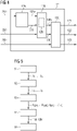
- FIG. 3 shows a block diagram of the CPC module 11.
- This module 11 implements a first state space model 11M in an explicit discrete time-variant system representation:
- X k + 1 A CPC k X k + B CPC k ⁇ k ⁇ k ⁇ k
- PitchCol k C CPC k X k + D CPC k ⁇ k a k ⁇ k where k is the current sample;
- X is the state vector of this state-space model 11M;
- PitchCol is the output variable or common pitch term 110;
- a CPC , B CPC , C CPC , D CPC are state-space matrices of this state-space model 11M, previously configured for this specific wind turbine in the optimisation process explained in more detail below.
- Components of the input or control vector are current values of generator speed ⁇ (generator speed 270 in Figure 2 ), nacelle acceleration ⁇ (nacelle acceleration 260 in Figure 2 ) and wind speed v (the wind speed component 250x of the wind vector 250 in Figure 2 ).
- the collective pitch term PitchCol is obtained from the previously computed state vector X, the output matrix C, and the feedforward matrix D.
- the computational steps are executed by the control algorithm for each sample k.
- An exemplary sample time may be in the order of 100 ms, for example.
- Figure 4 shows a block diagram of the IPC module 12.
- a multivariable control block 12B implements a second state space model 12M to compute parameters from its inputs, namely the current wind yaw 12Ay, wind tilt 12At, and nacelle acceleration 260 values 260.
- Components of the control vector are: current wind yaw ⁇ and wind tilt ⁇ values (the 12Ay, 12At outputs from block 12A, respectively), and nacelle acceleration ⁇ (nacelle acceleration 260 in Figure 2 ).
- the output vector of the state-space model 12M comprises a pitch yaw value PitchYaw(k) and a PitchTilt(k) value, indicated as outputs 12By, 12Bt respectively in the diagram.
- PitchYaw and PitchTilt are pitch angles in the rotor plane stationary reference frame, and are generated by the IPC module to achieve two different control targets: to correct the alignment of the rotor plane, and to reduce nacelle side-to-side oscillations in spite of the wind disturbances.
- the computational steps are executed by the control algorithm for each sample k.
- block 12C performs a suitable transformation such as a Coleman transformation to transform the pitch yaw and pitch tilt parameters 12By, 12Bt (in the stationary reference frame) under consideration of the current rotor azimuth angle 280 into individual pitch terms 121, 122, 123 for the three rotor blades (in the rotating reference frame). Each of these is summed with the collective pitch term 110 to give the pitch setpoint or pitch reference for a specific rotor blade as indicated in Figure 2 .
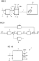
- Figure 5 shows a simplified block diagram to illustrate the steps of the inventive control synthesis method that is used to configure or customize a lidar-assisted wind turbine pitch controller.
- target control objectives J 1 , ..., J 5 are identified for that specific wind turbine.
- control specifications S1, ..., Sn are developed in the frequency domain from the target control objectives J 1 , ..., J 5 .
- state-space matrices A CPC , B CPC , C CPC , D CPC ; A IPC , B IPC , C IPC , D IPC are developed in a next stage 53 for the CPC module and IPC module of a pitch control algorithm which will fulfil the specifications.
- the control designer works with the frequency response of the linear time-invariant (LTI) system to fulfil the specifications S1, ..., Sn imposed by the control objectives J 1 , ..., J 5 , i.e. the control designer identifies state-space matrices for a pitch controller that will fulfil the specifications.
- LTI linear time-invariant
- the state-space matrices of each state space model 11M, 12M include a state or system matrix A; an input matrix B; an output matrix C; and a feedthrough or feedforward matrix D.
- the state-space matrices are developed in the frequency domain.
- the state-space models 11M, 12M are developed in step 54 to use a wind vector obtained from a lidar system as well as other relevant time-variant variables.
- the state-space models 11M, 12M are tested by performing closed-loop validation in the frequency domain. After validation, the control algorithm is stored in a memory of a controller such as a programmable logic controller (PLC) of that wind turbine.
- PLC programmable logic controller
- the state-space models of the inventive pitch control module 1 are developed in a multi-objective optimisation process.
- a starting point of the inventive multi-objective pitch control synthesis can be visualized as a pentagon, with five control objectives J 1 , ..., J 5 at the five corners of the pentagon, as shown in Figure 11 .
- the five control objectives are: optimization of (annual energy production) AEP J 1 , minimization of fatigue loads J 2 , minimization of structural extreme loads J 3 , optimization of generator speed regulation J 4 , and reduction in pitch duty activity J 5 .
- any control objective with a weighting factor of 0 is not considered during the optimization process.
- the magnitudes of the weighting factors can be visualized as affecting the shape of the pentagon: if all weighting factors are close to 0.2, the shape remains essentially a pentagon; if one or more of the weighting factors is significantly less than or greater than 0.2, the pentagonal shape will be "skewed".
- K 4 represents the generator speed regulation weighting factor in the cost function of equation (7).
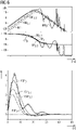
- Figure 6 shows proposed specifications (curves 6M, 6P) for different K values (0, 0.3, 0.7, 1) for the generator speed response as a function of wind speed in the frequency domain, showing generator speed magnitude [dB] and phase [°] against frequency [Hz], and a step response (curves 6SR) of generator speed as a function of wind speed in the time domain.
- a value of 0 for the weighting factor K 4 corresponds to the conventional approach (represented by curve 6M 0 ), and such a specification will not improve on the tradition control performance.
- the inventive lidar-assisted pitch control focusses entirely on improving the generator speed regulation.
- the inventive pitch controller achieves an improvement in generator speed regulation, while at the same time achieving an improvement for the other control objectives J 1 , J 2 , J 3 , J 5 , depending on the magnitudes of their respective weighting factors.
- a set of candidate specifications is identified, i.e. a set of suitable specifications for the five control objectives J 1 - J 5 .
- the state-space matrices of the state-space models 11M, 12M are developed in an iterative process that will fulfil the specifications.
- the aim of the control synthesis is to solve the cost function (5) by developing state-space models 11M, 12M for collective and individual pitch control that will ensure that the specifications are fulfilled.
- Figure 7 is a Bode diagram illustrating a further exemplary stage in the control synthesis process of Figure 5 , with regard to another specification, i.e. the tower base load response as a function of wind velocity.
- the diagram shows the frequency-domain response of tower base load magnitude [dB] (curves 7M spec , 7M, 7M pa ) and phase [°] (curves 7P spec , 7P, 7M pa ) against frequency [Hz].
- Curves 7M spec , 7P spec represent the control specification, for example that the maximum amplitude of tower base load should be 10% less than what can be achieved by the conventional pitch control 7M pa , 7P pa .
- a specification 7M spec , 7P spec is derived from optimization of a cost function as explained above, and represents the different control objectives considered during the optimization process.
- Curves 7M pa , 7P pa represent the results of conventional pitch control that does not combine lidar measurements with other operating variables, resulting in a sub-optimal performance as evidenced by significant deviations from the specification 7M spec , 7P spec .
- the inventive pitch control achieves a closer adherence to the specifications 7M spec , 7P spec , particularly over frequency ranges where the wind measurements from a lidar system can augment the pitch control.
- Curves 7M, 7P represent the predicted outcome of control using the inventive method, for example at the closed-loop validation stage 54 of Figure 5 , demonstrating that the specification will be adhered to closely over the entire frequency range if the rotor blades of a wind turbine will be pitched using the inventive lidar-assisted pitch control. Similarly, the other specifications (e.g. output power as a function of wind, etc.) will influence the ultimate composition of the state-space matrices)
- FIG 8 is a block diagram to illustrate the inventive control synthesis method.
- appropriate specifications S1, ..., Sn are formulated in a preliminary design stage 52 (as explained in Figure 5 ).
- state space models 11M, 12M of a pitch control algorithm 1 are designed ("synthesized") in a subsequent stage 53, 54 (as explained in Figure 5 ) to compute individual pitch setpoints from a lidar wind vector 250 and other relevant inputs 260, 270, 280 (as described in Figures 3 - 4 ) to ensure that specifications S1, ..., Sn are met during operation of the wind turbine.
- the control algorithm 1 is loaded into the memory 80 of a wind turbine controller 8. As explained above, during operation of the wind turbine controlled by the wind turbine controller 8, the output of this pitch control algorithm 1 will be a set of pitch setpoints that are continually optimized to adapt to changing conditions during operation of the wind turbine, while fulfilling the wind turbine specifications.
- Figure 9 is a block diagram of a state-space model.
- the diagram shows an input u(k) representing the input variable(s) to that state-space model, and an output y(k) representing the output variable(s) of that state-space model.
- the state-space matrix operators are labelled A, B, C, D and represent the state-space matrices A CPC , B CPC , C CPC , D CPC of the first state-space model 11M, or the state-space matrices A IPC , B IPC , C IPC , D IPC of the second state-space model 12M.
- a state-space model combines various different paths from inputs, state vectors and matrix operators to generate its output.
- the control objectives and target specifications are first identified as described above, and the state-space matrices are then developed in an iterative process that will fulfil the specifications for that wind turbine.
- FIG 10 shows a prior art lidar-assisted pitch controller 4 of a variable-speed wind turbine.
- This known type of pitch controller computes pitch setpoints 40PS1, 40PS2, 40PS3 for three rotor blades of the wind turbine using wind information 41 obtained from a lidar system and generator speed 42 provided by an encoder.
- pitch setpoints can react reasonably well to changes in the wind, a drawback of the known pitch control systems is that they are not designed considering a multivariable control scenario.
- the pitch setpoints may, on the whole, achieve an acceptable level of performance
- the inability of the conventional pitch controllers to simultaneously consider the effects of multiple variables on multiple behavioural parameters means that the chosen pitch may frequently result in sub-optimal behaviour, leading to higher-than-necessary loading, higher-than-necessary fatigue levels, higher-than-necessary pitch duty, etc.
- the known approaches to pitch control ultimately result in an unfavourably high LCOE for a wind turbine.
- the inventive approach uses a multivariable control scenario to define different control targets and to use more information regarding wind turbine behaviour (generator speed, nacelle oscillation, rotor azimuth angle) and also wind vector information predicted for the rotor plane.
Landscapes
- Engineering & Computer Science (AREA)
- Life Sciences & Earth Sciences (AREA)
- Sustainable Development (AREA)
- Sustainable Energy (AREA)
- Chemical & Material Sciences (AREA)
- Combustion & Propulsion (AREA)
- Mechanical Engineering (AREA)
- General Engineering & Computer Science (AREA)
- Physics & Mathematics (AREA)
- Fluid Mechanics (AREA)
- Wind Motors (AREA)
Priority Applications (2)
| Application Number | Priority Date | Filing Date | Title |
|---|---|---|---|
| EP21382152.3A EP4050207A1 (fr) | 2021-02-24 | 2021-02-24 | Procédé de configuration d'un organe de commande de pas d'éolienne |
| PCT/EP2022/052208 WO2022179801A1 (fr) | 2021-02-24 | 2022-01-31 | Procédé de configuration d'un régulateur de pas d'éolienne |
Applications Claiming Priority (1)
| Application Number | Priority Date | Filing Date | Title |
|---|---|---|---|
| EP21382152.3A EP4050207A1 (fr) | 2021-02-24 | 2021-02-24 | Procédé de configuration d'un organe de commande de pas d'éolienne |
Publications (1)
| Publication Number | Publication Date |
|---|---|
| EP4050207A1 true EP4050207A1 (fr) | 2022-08-31 |
Family
ID=75223231
Family Applications (1)
| Application Number | Title | Priority Date | Filing Date |
|---|---|---|---|
| EP21382152.3A Ceased EP4050207A1 (fr) | 2021-02-24 | 2021-02-24 | Procédé de configuration d'un organe de commande de pas d'éolienne |
Country Status (2)
| Country | Link |
|---|---|
| EP (1) | EP4050207A1 (fr) |
| WO (1) | WO2022179801A1 (fr) |
Cited By (1)
| Publication number | Priority date | Publication date | Assignee | Title |
|---|---|---|---|---|
| EP4671535A1 (fr) * | 2024-06-27 | 2025-12-31 | Wobben Properties GmbH | Procédé de validation d'une éolienne |
Citations (1)
| Publication number | Priority date | Publication date | Assignee | Title |
|---|---|---|---|---|
| WO2013152776A1 (fr) * | 2012-04-13 | 2013-10-17 | Kk-Electronic A/S | Système de configuration pour un système de commande de turbine éolienne |
-
2021
- 2021-02-24 EP EP21382152.3A patent/EP4050207A1/fr not_active Ceased
-
2022
- 2022-01-31 WO PCT/EP2022/052208 patent/WO2022179801A1/fr not_active Ceased
Patent Citations (1)
| Publication number | Priority date | Publication date | Assignee | Title |
|---|---|---|---|---|
| WO2013152776A1 (fr) * | 2012-04-13 | 2013-10-17 | Kk-Electronic A/S | Système de configuration pour un système de commande de turbine éolienne |
Non-Patent Citations (3)
| Title |
|---|
| HASSAN H M ET AL: "Robust dynamic output feedback pitch control for flexible wind turbines", ENERGYTECH, 2012 IEEE, IEEE, 29 May 2012 (2012-05-29), pages 1 - 6, XP032237312, ISBN: 978-1-4673-1836-5, DOI: 10.1109/ENERGYTECH.2012.6304632 * |
| MAHMOOD MIRZAEI ET AL: "Individual pitch control using LIDAR measurements", CONTROL APPLICATIONS (CCA), 2012 IEEE INTERNATIONAL CONFERENCE ON, IEEE, 3 October 2012 (2012-10-03), pages 1646 - 1651, XP032297955, ISBN: 978-1-4673-4503-3, DOI: 10.1109/CCA.2012.6402691 * |
| YUAN YUAN ET AL: "Multivariable robust blade pitch control design to reject periodic loads on wind turbines", RENEWABLE ENERGY, PERGAMON PRESS, OXFORD, GB, vol. 146, 24 June 2019 (2019-06-24), pages 329 - 341, XP085904443, ISSN: 0960-1481, [retrieved on 20190624], DOI: 10.1016/J.RENENE.2019.06.136 * |
Cited By (1)
| Publication number | Priority date | Publication date | Assignee | Title |
|---|---|---|---|---|
| EP4671535A1 (fr) * | 2024-06-27 | 2025-12-31 | Wobben Properties GmbH | Procédé de validation d'une éolienne |
Also Published As
| Publication number | Publication date |
|---|---|
| WO2022179801A1 (fr) | 2022-09-01 |
Similar Documents
| Publication | Publication Date | Title |
|---|---|---|
| US10907612B2 (en) | Control of a wind turbine using real-time gain calculation | |
| EP3613982B1 (fr) | Procédé de commande de fonctionnement d'une éolienne | |
| EP3274584B1 (fr) | Commande d'un système d'éolienne à rotors multiples utilisant un dispositif de commande central pour calculer des objectifs de commande locaux | |
| US10975845B2 (en) | Control of a wind turbine using real-time blade model | |
| EP2479426B1 (fr) | Procédés et systèmes pour déterminer un signal de décalage d'angle de pas et pour contrôler la fréquence d'un rotor d'une éolienne pour le contrôle d'évitement de la vitesse | |
| US10683844B2 (en) | Control of a wind turbine taking fatigue measure into account | |
| EP3158191B1 (fr) | Commande d'éoliennes en réponse au cisaillement du vent | |
| EP3899250B1 (fr) | Commande des mouvements vibratoires latéraux et avant-arrière d'une éolienne | |
| EP3440346B1 (fr) | Commande d'une éolienne tenant compte du bruit | |
| US20200072192A1 (en) | Method for controlling a wind turbine | |
| EP4112919B1 (fr) | Commande d'un système de turbine éolienne à rotors multiples à l'aide de contrôleurs mpc locaux | |
| EP4050207A1 (fr) | Procédé de configuration d'un organe de commande de pas d'éolienne | |
| US20230314130A1 (en) | Method for detecting a blade misalignment of a rotor blade of a rotor of a wind turbine | |
| EP4002024B1 (fr) | Systèmes et procédés de commande multivariable d'un système de génération de puissance | |
| KR20230129930A (ko) | 풍력 터빈에서의 진동 | |
| US20240229767A9 (en) | Controlling a wind turbine with respect to dynamic stability | |
| EP4671531A1 (fr) | Système et procédé d'optimisation de commande d'une éolienne | |
| Njiri et al. | Disturbance Attenuation using Proportional-Integral-Observer for Wind Turbine Speed Regulation | |
| Mathiopoulos | Development of a self-tuned drive-train damper for utility-scale variable-speed wind turbines |
Legal Events
| Date | Code | Title | Description |
|---|---|---|---|
| PUAI | Public reference made under article 153(3) epc to a published international application that has entered the european phase |
Free format text: ORIGINAL CODE: 0009012 |
|
| STAA | Information on the status of an ep patent application or granted ep patent |
Free format text: STATUS: THE APPLICATION HAS BEEN PUBLISHED |
|
| AK | Designated contracting states |
Kind code of ref document: A1 Designated state(s): AL AT BE BG CH CY CZ DE DK EE ES FI FR GB GR HR HU IE IS IT LI LT LU LV MC MK MT NL NO PL PT RO RS SE SI SK SM TR |
|
| STAA | Information on the status of an ep patent application or granted ep patent |
Free format text: STATUS: THE APPLICATION HAS BEEN REFUSED |
|
| 18R | Application refused |
Effective date: 20220917 |