EP4050689A1 - Batterie, module de batterie, bloc-batterie et véhicule électrique - Google Patents
Batterie, module de batterie, bloc-batterie et véhicule électrique Download PDFInfo
- Publication number
- EP4050689A1 EP4050689A1 EP20890373.2A EP20890373A EP4050689A1 EP 4050689 A1 EP4050689 A1 EP 4050689A1 EP 20890373 A EP20890373 A EP 20890373A EP 4050689 A1 EP4050689 A1 EP 4050689A1
- Authority
- EP
- European Patent Office
- Prior art keywords
- battery
- housing
- partition plate
- sampling
- electrode core
- Prior art date
- Legal status (The legal status is an assumption and is not a legal conclusion. Google has not performed a legal analysis and makes no representation as to the accuracy of the status listed.)
- Pending
Links
Images


Classifications
-
- H—ELECTRICITY
- H01—ELECTRIC ELEMENTS
- H01M—PROCESSES OR MEANS, e.g. BATTERIES, FOR THE DIRECT CONVERSION OF CHEMICAL ENERGY INTO ELECTRICAL ENERGY
- H01M50/00—Constructional details or processes of manufacture of the non-active parts of electrochemical cells other than fuel cells, e.g. hybrid cells
- H01M50/50—Current conducting connections for cells or batteries
- H01M50/569—Constructional details of current conducting connections for detecting conditions inside cells or batteries, e.g. details of voltage sensing terminals
-
- H—ELECTRICITY
- H01—ELECTRIC ELEMENTS
- H01M—PROCESSES OR MEANS, e.g. BATTERIES, FOR THE DIRECT CONVERSION OF CHEMICAL ENERGY INTO ELECTRICAL ENERGY
- H01M50/00—Constructional details or processes of manufacture of the non-active parts of electrochemical cells other than fuel cells, e.g. hybrid cells
- H01M50/20—Mountings; Secondary casings or frames; Racks, modules or packs; Suspension devices; Shock absorbers; Transport or carrying devices; Holders
- H01M50/249—Mountings; Secondary casings or frames; Racks, modules or packs; Suspension devices; Shock absorbers; Transport or carrying devices; Holders specially adapted for aircraft or vehicles, e.g. cars or trains
-
- H—ELECTRICITY
- H01—ELECTRIC ELEMENTS
- H01M—PROCESSES OR MEANS, e.g. BATTERIES, FOR THE DIRECT CONVERSION OF CHEMICAL ENERGY INTO ELECTRICAL ENERGY
- H01M50/00—Constructional details or processes of manufacture of the non-active parts of electrochemical cells other than fuel cells, e.g. hybrid cells
- H01M50/20—Mountings; Secondary casings or frames; Racks, modules or packs; Suspension devices; Shock absorbers; Transport or carrying devices; Holders
- H01M50/298—Mountings; Secondary casings or frames; Racks, modules or packs; Suspension devices; Shock absorbers; Transport or carrying devices; Holders characterised by the wiring of battery packs
-
- H—ELECTRICITY
- H01—ELECTRIC ELEMENTS
- H01M—PROCESSES OR MEANS, e.g. BATTERIES, FOR THE DIRECT CONVERSION OF CHEMICAL ENERGY INTO ELECTRICAL ENERGY
- H01M50/00—Constructional details or processes of manufacture of the non-active parts of electrochemical cells other than fuel cells, e.g. hybrid cells
- H01M50/10—Primary casings; Jackets or wrappings
- H01M50/102—Primary casings; Jackets or wrappings characterised by their shape or physical structure
- H01M50/112—Monobloc comprising multiple compartments
-
- H—ELECTRICITY
- H01—ELECTRIC ELEMENTS
- H01M—PROCESSES OR MEANS, e.g. BATTERIES, FOR THE DIRECT CONVERSION OF CHEMICAL ENERGY INTO ELECTRICAL ENERGY
- H01M50/00—Constructional details or processes of manufacture of the non-active parts of electrochemical cells other than fuel cells, e.g. hybrid cells
- H01M50/10—Primary casings; Jackets or wrappings
- H01M50/183—Sealing members
- H01M50/184—Sealing members characterised by their shape or structure
-
- H—ELECTRICITY
- H01—ELECTRIC ELEMENTS
- H01M—PROCESSES OR MEANS, e.g. BATTERIES, FOR THE DIRECT CONVERSION OF CHEMICAL ENERGY INTO ELECTRICAL ENERGY
- H01M50/00—Constructional details or processes of manufacture of the non-active parts of electrochemical cells other than fuel cells, e.g. hybrid cells
- H01M50/20—Mountings; Secondary casings or frames; Racks, modules or packs; Suspension devices; Shock absorbers; Transport or carrying devices; Holders
- H01M50/204—Racks, modules or packs for multiple batteries or multiple cells
- H01M50/207—Racks, modules or packs for multiple batteries or multiple cells characterised by their shape
- H01M50/209—Racks, modules or packs for multiple batteries or multiple cells characterised by their shape adapted for prismatic or rectangular cells
-
- H—ELECTRICITY
- H01—ELECTRIC ELEMENTS
- H01M—PROCESSES OR MEANS, e.g. BATTERIES, FOR THE DIRECT CONVERSION OF CHEMICAL ENERGY INTO ELECTRICAL ENERGY
- H01M50/00—Constructional details or processes of manufacture of the non-active parts of electrochemical cells other than fuel cells, e.g. hybrid cells
- H01M50/50—Current conducting connections for cells or batteries
- H01M50/502—Interconnectors for connecting terminals of adjacent batteries; Interconnectors for connecting cells outside a battery casing
- H01M50/503—Interconnectors for connecting terminals of adjacent batteries; Interconnectors for connecting cells outside a battery casing characterised by the shape of the interconnectors
-
- H—ELECTRICITY
- H01—ELECTRIC ELEMENTS
- H01M—PROCESSES OR MEANS, e.g. BATTERIES, FOR THE DIRECT CONVERSION OF CHEMICAL ENERGY INTO ELECTRICAL ENERGY
- H01M50/00—Constructional details or processes of manufacture of the non-active parts of electrochemical cells other than fuel cells, e.g. hybrid cells
- H01M50/50—Current conducting connections for cells or batteries
- H01M50/502—Interconnectors for connecting terminals of adjacent batteries; Interconnectors for connecting cells outside a battery casing
- H01M50/509—Interconnectors for connecting terminals of adjacent batteries; Interconnectors for connecting cells outside a battery casing characterised by the type of connection, e.g. mixed connections
- H01M50/51—Connection only in series
-
- H—ELECTRICITY
- H01—ELECTRIC ELEMENTS
- H01M—PROCESSES OR MEANS, e.g. BATTERIES, FOR THE DIRECT CONVERSION OF CHEMICAL ENERGY INTO ELECTRICAL ENERGY
- H01M50/00—Constructional details or processes of manufacture of the non-active parts of electrochemical cells other than fuel cells, e.g. hybrid cells
- H01M50/50—Current conducting connections for cells or batteries
- H01M50/502—Interconnectors for connecting terminals of adjacent batteries; Interconnectors for connecting cells outside a battery casing
- H01M50/519—Interconnectors for connecting terminals of adjacent batteries; Interconnectors for connecting cells outside a battery casing comprising printed circuit boards [PCB]
-
- B—PERFORMING OPERATIONS; TRANSPORTING
- B60—VEHICLES IN GENERAL
- B60Y—INDEXING SCHEME RELATING TO ASPECTS CROSS-CUTTING VEHICLE TECHNOLOGY
- B60Y2200/00—Type of vehicle
- B60Y2200/90—Vehicles comprising electric prime movers
- B60Y2200/91—Electric vehicles
-
- H—ELECTRICITY
- H01—ELECTRIC ELEMENTS
- H01M—PROCESSES OR MEANS, e.g. BATTERIES, FOR THE DIRECT CONVERSION OF CHEMICAL ENERGY INTO ELECTRICAL ENERGY
- H01M2220/00—Batteries for particular applications
- H01M2220/20—Batteries in motive systems, e.g. vehicle, ship, plane
-
- Y—GENERAL TAGGING OF NEW TECHNOLOGICAL DEVELOPMENTS; GENERAL TAGGING OF CROSS-SECTIONAL TECHNOLOGIES SPANNING OVER SEVERAL SECTIONS OF THE IPC; TECHNICAL SUBJECTS COVERED BY FORMER USPC CROSS-REFERENCE ART COLLECTIONS [XRACs] AND DIGESTS
- Y02—TECHNOLOGIES OR APPLICATIONS FOR MITIGATION OR ADAPTATION AGAINST CLIMATE CHANGE
- Y02E—REDUCTION OF GREENHOUSE GAS [GHG] EMISSIONS, RELATED TO ENERGY GENERATION, TRANSMISSION OR DISTRIBUTION
- Y02E60/00—Enabling technologies; Technologies with a potential or indirect contribution to GHG emissions mitigation
- Y02E60/10—Energy storage using batteries
Definitions
- the present disclosure relates to the field of batteries, and specifically, to a battery, a battery module, a battery pack, and an electric vehicle.
- the usage requirements for power batteries in the new energy vehicles are increasingly high.
- the overall capacity of batteries of the new energy vehicles needs to be continuously increased.
- a high voltage (high capacity) is required, a large number of electrode cores are connected in series to form an electrode core assembly, and then multiple electrode core assemblies are assembled into a power battery.
- power connection between two adjacent electrode cores needs to be achieved through an external power connector, which may result in more overall installation structures of the power battery, which increases the costs, and the overall weight.
- the installation structures occupy a larger part of an internal space of the power battery, which reduces the overall space utilization of the power battery.
- More electrode cores arranged side by side indicate a more wasted space.
- information of the electrode core assemblies in aspects of current, voltage, and temperature generally needs to be obtained in time, to better manage the power battery.
- the electrode core assemblies are inside the power battery, and after a housing of the power battery is sealed, signals such as the voltage, current, temperature of the electrode core assemblies inside the power battery cannot be acquired in real time. Therefore, how to acquire the signals of the multiple electrode core assemblies inside the battery is also a difficult problem that needs to be resolved in manufacture of the power battery.
- This application provides a battery, including: a housing; multiple accommodating cavities arranged in the housing; a partition plate for separating two adjacent accommodating cavities; an electrode core assembly, received in one of the accommodating cavities, the electrode core assembly including at least one electrode core, and multiple electrode core assemblies being sequentially arranged in a first direction and connected in series; multiple sampling wires, electrically connected to the multiple electrode core assemblies correspondingly; and a wire harness channel, receiving the multiple sampling wires.
- This application further provides a battery module, including the foregoing battery.
- This application further provides a battery pack, including the foregoing battery or the foregoing battery module.
- This application further provides an electric vehicle, including the foregoing battery module or the foregoing battery pack.
- the multiple electrode core assemblies are connected in series in the housing of the battery, which can increase capacity of the battery, improve connection stability between the electrode core assemblies, and reduce a manufacturing process and costs.
- all sampling wires are fixed through the wire harness channel in order in this application, thereby improving sampling accuracy of the entire battery and safety of sampling wire harnesses.
- orientation or position relationships indicated by the terms such as “center”, “longitudinal”, “transverse”, “length”, “width”, “thickness”, “on”, “below”, “front”, “back”, “left”, “right”, “vertical”, “horizontal”, “top”, “bottom”, “inside”, “outside”, “axial direction”, “radial direction”, and “circumferential direction” are based on orientation or position relationships shown in the accompanying drawings, and are used only for ease and brevity of illustration and description for this application, rather than indicating or implying that the mentioned apparatus or component must have a particular orientation or must be constructed and operated in a particular orientation. Therefore, such terms should not be construed as limiting of this application.
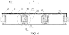
- a first embodiment of this application provides a battery 100, and the battery 100 includes a housing 10, a partition plate 20, an electrode core assembly 30, a sampling wire 50, and a wire harness channel 54.
- Multiple accommodating cavities 60 are formed in the housing 10, and two adjacent accommodating cavities 60 are separated by the partition plate 20.
- the electrode core assembly 30 is received in one of the accommodating cavities 60, and the electrode core assembly 30 includes at least one electrode core.
- Multiple electrode core assemblies 30 are sequentially arranged in a first direction.
- Multiple sampling wires 50 are electrically connected to the multiple electrode core assemblies 30 correspondingly, and the sampling wires 50 are received in the wire harness channel 54.
- the multiple electrode core assemblies 30 are connected in series in the housing 10 of the battery 100, which can increase capacity of the battery 100, improve connection stability between the electrode core assemblies 30, and reduce a manufacturing process and costs. All sampling wires are fixed through the wire harness channel in order in this application, thereby improving sampling accuracy of the entire battery and safety of sampling wire harnesses.
- the first direction may be a long direction of the battery 100, for example, the first direction is an X direction shown in FIG. 4 .
- FIG. 6 , FIG. 8 , FIG. 19, FIG. 21 , and the like are also similar to FIG. 4 , that is, a direction of a landscape paper is the first direction, which is not further described and labeled below.
- the involved electrode core is an electrode core commonly used in the field of power batteries 100, and the electrode core and the electrode core assembly 30 are components inside the housing 10 of the battery 100, which are not to be understood as the battery 100 itself.
- the electrode core may be an electrode core formed by winding, or an electrode core made in a laminated manner. Generally, the electrode core at least includes an anode plate, a separator, a cathode plate, and an electrolyte solution.
- the electrode core is generally a component that is not completely sealed.
- an electrode core assembly 30 may be formed by a single electrode core, or may include at least two electrode cores. The at least two electrode cores are connected in parallel to form the electrode core assembly 30.
- the electrode core assembly 30 is formed after two electrode cores are connected in parallel; or after four electrode cores are connected in parallel, the electrode core assembly 30 is formed. Therefore, the battery 100 involved in this application cannot be simply understood as a battery module or a battery pack because the battery includes multiple electrode cores.
- the number of electrode core assemblies 30 connected in series in the battery 100 may be determined according to an output voltage of each electrode core assembly 30, a width of a battery pack, and an overall voltage requirement for the battery pack. For example, a voltage systematically outputted by a battery 100 required by a vehicle is 300 V, and a voltage of a conventional iron-lithium battery 100 is 3.2 V. In the related art, the requirement can be met in a case that 100 batteries 100 are connected in series in a battery pack. However, in this application, assuming that two electrode core assemblies 30 are connected in series inside one battery 100, only 50 batteries 100 need to be arranged. By analogy, if ten electrode core assemblies 30 are connected in series, only ten batteries 100 need to be connected in series. That is, by using the battery 100 in this application, the number of batteries 100 in the entire battery pack can be reduced, thereby effectively utilizing a space of the battery pack, and improving space utilization of the battery pack.
- the series connection between the electrode core assemblies 30 may be that the multiple electrode core assemblies 30 are sequentially connected in series, or the electrode core assemblies 30 are connected in series at intervals.
- the first electrode core assembly 30 and the third electrode core assembly 30 may be connected in series to form a first series of electrode core assemblies 30, the second electrode core assembly 30 and the fourth electrode core assembly 30 may be connected in series to form a second series of electrode core assemblies 30, and then the first series of electrode core assemblies 30 and the second series of electrode core assemblies 30 are connected in series.
- the partition plate 20 is arranged between adjacent electrode core assemblies 30.
- the partition plate 20 itself may be selected to be made of an insulating material, that is, the partition plate 20 is an insulating partition plate 20. In this way, without other operations, the two adjacent electrode core assemblies 30 may be directly separated by the partition plate 20 and insulation between the two may be maintained.
- the partition plates 20 separate an accommodating space into several accommodating cavities 60, and each of the accommodating cavities 60 accommodates the electrode core assembly 30, that is, two adjacent accommodating cavities 60 share one partition plate 20.
- each accommodating cavity 60 may accommodate one electrode core assembly 30, or may accommodate multiple electrode core assemblies 30, for example, two or three. In some preferred implementations, each accommodating cavity 60 accommodates one electrode core assembly 30.
- the battery 100 further includes end covers 70 formed at two ends of the battery 100 in the first direction.
- the housing 10 may be an integral structure extending in the first direction, or may include multiple sub-housings 11 arranged in the first direction.
- the housing 10 is an integral structure extending in the first direction, and the end covers 70 are arranged at two ends of the housing 10 in the first direction, to enclose an internal space of the housing 10.
- Multiple partition plates 20 are arranged in the housing 10 at intervals, and side circumferences of the partition plates 20 cooperate with side walls of the housing 10, to separate an interior of the housing 10 into the multiple accommodating cavities 60.
- the accommodating cavity 60 at an end portion of the battery 100 in the first direction is an end portion accommodating cavity
- the accommodating cavity 60 in a middle position of the battery 100 is a middle accommodating cavity
- cavity walls of the end portion accommodating cavity include the end cover 70, the partition plate 20, and part of the housing 10 arranged between the end cover 70 and the partition plate 20
- cavity walls of the middle accommodating cavity include two adjacent partition plates 20 and part of the housing 10 arranged between the two adjacent partition plates 20.
- the end cover 70 at one end of the housing 10 and the housing 10 may be integrally formed, and the end cover 70 at the other end of the housing 10 and the housing 10 may be sealedly connected in a direct or indirect connection manner.
- the end cover 70 and the housing 10 are sealedly connected by welding or adhesion, or the end cover 70 may be fixedly and sealedly connected to the housing 10 by a connection member, to enclose the internal space of the housing 10.
- Both the two ends of the housing 10 and one end cover 70 may also be sealedly connected in a direct or indirect connection manner, for example, may be sealedly connected by welding or adhesion, or be fixedly and sealedly connected by a connection member.
- the side circumferences of the partition plates 20 refer to circumferential surfaces of the partition plates 20 toward the housing 10, and cooperation between the side circumferences of the partition plates 20 and the side walls of the housing 10 is not specifically limited, for example, a cooperation manner of interference fit or adhesion.
- the housing 10 includes multiple sub-housings 11 arranged in the first direction, two adjacent sub-housings 11 are connected to one partition plate 20, and a housing opening is formed at the end portion of the housing 10 in the first direction as a whole.
- the housing opening is formed at one end of an outermost sub-housing 11 away from the partition plate, the housing opening formed at the one end cooperates with the end cover 70, and the end cover 70 is connected to the housing and encloses the housing opening.
- the accommodating cavity 60 at an end portion of the battery 100 in the first direction is an end portion accommodating cavity
- the accommodating cavity 60 in a middle position of the battery 100 is a middle accommodating cavity
- cavity walls of the end portion accommodating cavity include the end cover 70, the partition plate 20, and the sub-housing 11 arranged between the end cover 70 and the partition plate 20
- cavity walls of the middle accommodating cavity include two adjacent partition plates 20 and the sub-housing 11 arranged between the two adjacent partition plates 20.
- part of the side circumference of the partition plate 20 is exposed to the housing 10, and part of the side circumference covers the housing 10.
- the housing 10 is made of a corrosive material, for example, an aluminum housing
- the electrode core assemblies 30 when the electrode core assemblies 30 are connected in series, lithium ions are embedded inside the housing 10 due to different voltages between different electrode core assemblies 30, to form a lithium aluminum alloy, which corrodes the aluminum housing.
- a separator film 80 may be arranged between the housing 10 and the electrode core assemblies 30, and is used for separating contact between electrolyte solutions and the housing 10.
- the housing 10 is an integral structure extending in the first direction; and a separator film 80 is arranged in the housing 10, the separator film 80 includes multiple sub-separator films 81 arranged in the first direction, two adjacent sub-separator films 81 are sealedly connected to one partition plate 20, and a separator film opening is formed on an end portion of the separator film 80 in the first direction as a whole.
- the separator film 80 includes multiple sub-separator films 81 arranged in the first direction, two adjacent sub-separator films 81 are sealedly connected to one partition plate 20, and a separator film opening is formed on an end portion of the separator film 80 in the first direction as a whole.
- the separator film opening is formed at one end of an outermost sub-separator film away from the partition plate, the separator film opening formed on the one end cooperates with the end cover 70, and the end cover 70 is connected to the separator film 80 and encloses the separator film opening.
- the accommodating cavity 60 at an end portion of the battery 100 in the first direction is an end portion accommodating cavity
- the accommodating cavity 60 in a middle position of the battery 100 is a middle accommodating cavity
- cavity walls of the end portion accommodating cavity include the end cover 70, the partition plate 20, and the sub-separator film 81 arranged between the end cover 70 and the partition plate 20
- cavity walls of the middle accommodating cavity include two adjacent partition plates 20 and the sub-separator film 81 arranged between the two adjacent partition plates 20.
- the two ends of the housing 10 in the first direction and the corresponding end covers 70 may also be sealedly connected in a direct or indirect connection manner, for example, may be sealedly connected by welding or adhesion, or be fixedly and sealedly connected by a connection member.
- the multiple sub-separator films 81 are multiple independent parts separated from each other, that is, the separator film 80 is a split-type separator film body.
- Each of the sub-separator films 81 is of a tubular structure with openings on two ends, and the electrode core assembly 30 is arranged inside the tubular sub-separator film 81.
- the partition plate 20 or the end cover 70 and an opening of the corresponding separator film 80 are sealedly connected, to form the accommodating cavity.
- the sealed connection manner between the separator film 80 and the partition plate 20 or the end cover 70 and a specific structure thereof are not specifically limited.
- the partition plate 20 or the end cover 70 is made of a plastic material and the separator film 80 is made of plastic
- sealed connection of hot melt may be used between the separator film 80 and the partition plate 20 or the end cover 70
- the housing 10 is an integral structure extending in the first direction; a separator film 80 is arranged in the housing 10, the separator film 80 is also an integral structure extending in the first direction, and a separator film opening is formed at an end portion of the separator film 80 in the first direction; the side circumferences of the partition plates 20 cooperate with side walls of the separator film 80, to separate an interior of the separator film 80 into the multiple accommodating cavities 60; and the end covers 70 are connected to the separator film 80 and enclose the separator film opening.
- the accommodating cavity 60 at an end portion of the battery 100 in the first direction is an end portion accommodating cavity
- the accommodating cavity 60 in a middle position of the battery 100 is a middle accommodating cavity
- cavity walls of the end portion accommodating cavity include the end cover 70, the partition plate 20, and part of the separator film 80 arranged between the end cover 70 and the partition plate 20
- cavity walls of the middle accommodating cavity include two adjacent partition plates 20 and part of the separator film 80 arranged between the two adjacent partition plates 20.
- the two ends of the housing 10 in the first direction and the corresponding end covers 70 may also be sealedly connected in a direct or indirect connection manner, for example, may be sealedly connected by welding or adhesion, or be fixedly and sealedly connected by a connection member.
- the separator film 80 may be sealedly connected to the partition plates 20 in a hot melt manner.
- a separator film 80 is arranged in the housing 10, the separator film 80 includes multiple sub-separator films 81 arranged in the first direction, two adjacent sub-separator films 81 are sealedly connected to one partition plate 20, the housing 10 includes multiple sub-housings 11 arranged in the first direction, and each of the multiple sub-separator films 81 is correspondingly received in one of the sub-housings 11; a separator film opening is formed at an end portion of the separator film 80 in the first direction as a whole; and the end covers 70 are connected to the separator film 80 and enclose the separator film opening.
- the accommodating cavity 60 at an end portion of the battery 100 in the first direction is an end portion accommodating cavity
- the accommodating cavity 60 in a middle position of the battery 100 is a middle accommodating cavity
- cavity walls of the end portion accommodating cavity include the end cover 70, the partition plate 20, and the sub-separator film 81 arranged between the end cover 70 and the partition plate 20
- cavity walls of the middle accommodating cavity include two adjacent partition plates 20 and the sub-separator film 81 arranged between the two adjacent partition plates 20.
- the two ends of the housing 10 in the first direction as a whole and the corresponding end covers 70 may also be sealedly connected in a direct or indirect connection manner, for example, may be sealedly connected by welding or adhesion, or be fixedly and sealedly connected by a connection member.
- the material of the separator film 80 is not specially limited, as long as the material has certain insulation and electrolyte solution corrosion resistance, and can provide insulation and does not react with an electrolyte solution.
- the material of the separator film 80 may include polypropylene (PP), polyethylene (PE), or a multi-layer composite film.
- the multi-layer composite film may include, for example, an inner layer, an outer layer, and an intermediate layer arranged between the inner layer and the outer layer.
- the inner layer may include a plastic material, for example, may be made of an insulative material less reactive to an electrolyte solution in the separator film 80.
- the inner layer may include a PP or PE material.
- the intermediate layer may include a metal material, which can prevent vapor outside from entering the battery 100 and prevent the electrolyte solution inside from leaking out of the battery.
- a metal material which can prevent vapor outside from entering the battery 100 and prevent the electrolyte solution inside from leaking out of the battery.
- Aluminum foil, stainless steel foil, copper foil, or the like are preferably selected as the metal material, and considering the molding performance, weight, and costs, the aluminum foil is preferable.
- priority is given to pure aluminum or aluminum-iron-based alloy materials.
- the outer layer is a protective layer, and may be made of a high melting point polyester or nylon material, to provide strong mechanical performance and prevent an external force from damaging the battery 100, so as to protect the battery 100.
- an inner film is a multi-layer composite film, one implementation is that, the inner film is an aluminum-plastic composite film.
- the separator film 80 has certain flexibility, which facilitates a molding process of the battery 100 and prevents the battery from being punctured.
- a thickness of the separator film 80 is preferably 80 ⁇ m to 200 ⁇ m, and may be certainly adjusted according to actual situations.
- the electrolyte solution is a core component forming the battery 100, and the electrolyte solution needs to be filled into the accommodating cavity 60 in the battery 100 of this application. Therefore, an electrolyte solution channel is further arranged in the battery 100 of this application, the electrolyte solution channel is in communication with the accommodating cavity 60, and the electrolyte solution may be filled in the accommodating cavity 60 through the electrolyte solution channel.
- the electrolyte solution channels may be arranged on components such as the partition plate 20, the housing 10, the end cover 70, and the separator film 80.
- the electrolyte solution channel includes an electrolyte solution filling channel 91
- the electrolyte solution filling channel 91 is arranged on the partition plate 20 and is used for filling an electrolyte solution from the exterior of the battery 100 into the accommodating cavity 60
- the electrolyte solution filling channel 91 is in communication with the accommodating cavity 60 at least one side of the partition plate 20.
- the electrolyte solution filling channel 91 is in an enclosed state after electrolyte solution filling is completed, to separate communication between the accommodating cavity 60 and the exterior of the battery 100.
- a sealing portion 92 may be arranged in the electrolyte solution filling channel 91, and the sealing portion 92 seals the electrolyte solution filling channel 91.
- the electrolyte solution filling channel 91 may also be in communication with the accommodating cavities 60 at two sides of the partition plate 20 respectively.
- the sampling wire 50 and the electrolyte solution filling channel 91 may be staggered (the sampling wire 50 is represented by a dash line in the figures).
- a through hole may also be arranged at a position at which the housing 10 corresponds to the electrolyte solution filling channel 91 on the partition plate 20, and the through hole is used for communicating the electrolyte solution filling channel 91 and the exterior of the battery 100.
- the structure of the battery 100 corresponds to that of the embodiments in FIG. 5 and FIG. 6
- the electrolyte solution filling channel 91 may also be in direct communication with the exterior of the battery 100 from the part of the exposed side circumference of the partition plate 20.
- the electrolyte solution filling channel 91 may also be arranged on the separator film 80.
- the electrolyte solution filling channel 91 is used for filling an electrolyte solution from the exterior of the battery 100 into the accommodating cavity 60, and the electrolyte solution filling channels 91 are in communication with the corresponding accommodating cavities 60.
- the electrolyte solution filling channel 91 is in an enclosed state after electrolyte solution filling is completed, to separate communication between the accommodating cavity 60 and the exterior of the battery 100.
- the separator film 80 when the separator film 80 is made of plastic, hot melt is used for sealing, which can meet a sealing requirement for an electrolyte solution filling hole, and is more convenient to seal.
- the separator film 80 includes a body of the separator film 80 and a protrusion protruding outward from the body of the separator film 80.
- an opening may be arranged on the protrusion, as the electrolyte solution filling channel 91. After electrolyte solution filling is completed, the protrusion with the opening may be sealed and tightened by hot melt.
- the battery 100 further includes the separator film 80, the separator film 80 and the partition plate 20 form the accommodating cavity 60. Therefore, whether the electrolyte solution filling channel 91 is arranged on the partition plate 20 or the separator film 80, electrolyte solution may be filled into the battery 100, and then the housing 10 is mounted. In this way, the housing 10 has a secondary sealing effect on the electrolyte solution filling channel 91, and the sealing performance of the entire battery 100 is significantly improved. Once electrolyte solution leakage occurs in one of the accommodating cavities 60, the housing 10 provides a protection effect, to avoid a safety problem resulted from the electrolyte solution leakage.
- the electrolyte solution channel may also include an electrolyte solution guide hole 93, an electrolyte solution guide hole 93 used for allowing the electrolyte solution to pass through is arranged on at least one partition plate 20, and the electrolyte solution guide hole 93 is used for communicating two adjacent accommodating cavities 60 at two sides of the partition plate 20.
- the battery 100 further includes a blocking mechanism 94, the blocking mechanism 94 is arranged in the housing 10, the blocking mechanism 94 enables the electrolyte solution guide hole 93 to be in a set state, and the set state includes an open state and a closed state.
- the blocking mechanism 94 may switch between the first situation and the second situation. For example, before or during the electrolyte solution filling of the battery 100, the blocking mechanism 94 is in the first situation, the electrolyte solution guide hole 93 is in the open state, and the electrolyte solution guide hole 93 is in communication with the two adjacent accommodating cavities 60 at the two sides of the partition plate 20.
- the blocking mechanism 94 switches from the first situation to the second situation, and the blocking mechanism 94 closes the electrolyte solution guide hole 93, so that the electrolyte solution guide hole 93 is in the closed state.
- the blocking mechanism 94 is in the first situation, the electrolyte solution guide hole 93 is in the open state, and the electrolyte solution guide hole 93 is in communication with the two adjacent accommodating cavities 60 at the two sides of the partition plate 20.
- the blocking mechanism 94 switches from the first situation to the second situation, and the blocking mechanism 94 closes the electrolyte solution guide hole 93, so that the electrolyte solution guide hole 93 is in the closed state.
- the blocking mechanism 94 switches from the second situation to the first situation, the blocking mechanism 94 enables the electrolyte solution guide hole 93 to be in the open state, and the electrolyte solution guide hole 93 is in communication with the two adjacent accommodating cavities 60 at the two sides of the partition plate 20.
- the blocking mechanism 94 may be received in a blocking mechanism placement space 941, and the blocking mechanism placement space 941 and the electrolyte solution guide hole 93 may be intersected.
- the blocking mechanism 94 is a metal ball with a rubber sleeve. In this solution, the metal ball ensures sealing strength, while the rubber sleeve improves sealing tightness.
- the sampling wire 50 and the electrolyte solution guide hole 93 may be staggered (the sampling wire 50 is represented by a dash line in the figure).
- the electrolyte solution channel further includes an electrolyte solution filling hole, and the electrolyte solution filling hole may be arranged on the end cover 70.
- electrolyte solution is only filled from electrolyte solution filling holes on the end covers 70 on the end portions of the battery 100, and the electrolyte solution is guided from the electrolyte solution guide holes 93 on the partition plates 20 into the accommodating cavities 60.
- the electrolyte solution filling holes By arranging the electrolyte solution filling holes, the electrolyte solution can be filled into the accommodating cavities 60 once, and there is no need to open for multiple times to perform electrolyte solution filling for multiple times.
- the electrolyte solution filling holes may also be arranged on the housing 10, the partition plates 20, or the separator film 80, and the electrolyte solution filling principle thereof is similar to that of the electrolyte solution filling holes arranged on the end covers 70.
- each of the electrode core assemblies 30 includes a first electrode lead-out member 32 and a second electrode lead-out member 33 used for leading out current, and the first electrode lead-out member 32 and the second electrode lead-out member 33 of at least one electrode core assembly 30 are respectively arranged at two opposite sides of the electrode core assembly 30 in the first direction.
- All electrode core assemblies 30 in the battery 100 are arranged in the first direction, and the first direction is a length direction of the battery 100. That is, the battery 100 adopts "head-to-head" arrangement of the electrode core assemblies 30, which can relatively facilitate series connection between every two of the electrode core assemblies 30 in the battery 100, and provide a simple connection structure. In addition, this arrangement can relatively facilitate manufacturing of batteries 100 with a longer length.
- the first electrode lead-out member 32 and the second electrode lead-out member 33 may be respectively an anode tab and a cathode tab of the electrode core, or may be respectively a cathode tab and an anode tab. If the electrode core assembly includes multiple electrode cores, the first electrode lead-out member 32 and the second electrode lead-out member 33 may be electrode lead wires. It should be noted that, “first" and “second" in the first electrode lead-out member 32 and the second electrode lead-out member 33 are only used for distinguishing names, not to limit the number. For example, there may be one or more first electrode lead-out members 32.
- two adjacent electrode core assemblies 30 are connected in series by an electrode core connector 40.
- the electrode core connector 40 penetrates the partition plate 20 between the two adjacent electrode core assemblies 30. Ends of the electrode core connector 40 are electrically connected to the first electrode lead-out member 32 and the second electrode lead-out member 33 of the electrode core assemblies 30 at two sides of the partition plate 20 in the first direction. That is, in the electrode core assemblies 30, the first electrode lead-out member 32 of one electrode core assembly 30 is electrically connected to the second electrode lead-out member 33 of an adjacent electrode core assembly 30 by the electrode core connector 40.
- the electrode lead-out members and the electrode core connector 40 in the partition plate 20 are directly welded.
- the two adjacent electrode core assemblies 30 are connected by the electrode core connector 40 penetrating the partition plate 20, which reduces a spacing between the two electrode core assemblies 30, and can give a greater design space for the battery 100.
- an aperture in the interior of the battery 100 can be saved, and an open area between the two adjacent electrode core assemblies 30 is increased, so that internal resistance of the battery 100 is reduced.
- the electrode core connector 40 includes a copper connection piece 41 and an aluminum connection piece 42, the copper connection piece 41 is electrically connected to the aluminum connection piece 42, and a position at which the copper connection piece is electrically connected to the aluminum connection piece is arranged inside the partition plate 20.
- the copper connection piece 41 is connected to a copper lead-out end of the electrode core assembly 30 at one side of the partition plate 20
- the aluminum connection piece 42 is connected to an aluminum lead-out end of the electrode core assembly 30 at the other side of the partition plate 20.
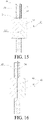
- connection and a position relationship between the electrode core connector 40 and the partition plate 20 are shown in FIG. 15 .
- a connection through hole 21 is arranged on the partition plate 20, and the electrode core connector 40 penetrates through the connection through hole 21 from one side of the connection through hole 21 to the other side. That is, the electrode core connector 40 passes through the connection through hole 21.
- one end of the electrode core connector 40 is connected to the electrode core assembly 30 at one side of the partition plate, and the other end of the electrode core connector 40 is connected to the electrode core assembly 30 at the other side of the partition plate 20.
- an encapsulated structure 22 is arranged in the connection through hole 21, and the encapsulated structure 22 encapsulates the electrode core connector 40 in the connection through hole 21. Meanwhile, the encapsulated structure 22 can enclose the connection through hole 21, to separate the adjacent electrode core accommodating cavities 60 at the two sides of the partition plate 20.
- the encapsulated structure 22 only needs to be capable of achieving sealing performance, electrolyte solution corrosion resistance, and insulation, for example, may be a rubber plug.
- connection and a position relationship between the electrode core connector 40 and the partition plate 20 are shown in FIG. 16 .
- the electrode core connector 40 and the partition plate 20 are integrally injection-molded. Specifically, the electrode core connector 40 is first manufactured, and then the partition plate 20 is integrally injection-molded outside the electrode core connector 40. More specifically, the copper connection piece 41 and the aluminum connection piece 42 are compositely connected, to form a composite connection piece; and then the partition plate 20 is integrally injection-molded and formed outside the composite connection piece.
- a contact position (the composite connection piece) of the copper connection piece 41 and the aluminum connection piece 42 is sealed inside the partition plate 20, which prevents the position from being exposed to an internal space of the battery 100, particularly preventing the position from being in contact with the electrolyte solution, thereby preventing the connected position of copper and aluminum from being corroded.
- the partition plate 20 and the electrode core connector 40 are integrally formed. Therefore, there is no need to assemble the partition plate 20 and the electrode core connector 40, and the electrode core assemblies 30 only need to be directly connected to the electrode core connector 40 on the partition plate 20, thereby simplifying the process.
- a connection through hole 21 is not formed on the partition plate 20, and there is no need to arrange an encapsulated structure 22 to seal the connection through hole 21, thereby reducing the risk.
- the sampling wires 50 may be arranged to be electrically connected to the electrode core connectors 40 and are leaded out from the partition plates 20 through the wire harness channel 54, thereby sampling each electrode core assembly 30 in the housing 10, to monitor a state of each electrode core assembly 30 to ensure safety and stability of the battery 100.
- the sampling wires 50 arranged in this application can resolve a sampling problem of the electrode core assemblies 30 connected in series inside the battery 100.
- the sampling wire 50 is welded to the aluminum connection piece 42, to be electrically connected to the electrode core assembly 30.
- a leading wire aperture 23 is formed in the partition plate 20, and the sampling wire 50 penetrates through the leading wire aperture 23 and is leaded out from the partition plate 20.
- a sealing material 24 for filling a gap may be arranged between the leading wire aperture 23 and the sampling wire 50.
- the partition plate 20 may be integrally injection-molded with the sampling wire 50 and the electrode core connector 40.
- the sampling wire 50 is tightly engaged with the partition plate 20, that is, there is no need to pre-arrange the leading wire aperture 23 and arrange the sealing material 24.
- a sampling hole is arranged on the battery 100, the sampling wire 50 is leaded out from the wire harness channel 54 to the sampling hole, and the sampling hole is used for leading out a sampling signal.
- the sampling hole 51 may be arranged on the housing 10, as shown in FIG. 14 .
- the sampling hole 51 may also be arranged on the end cover 70 (referring to FIG. 20 ).
- the multiple sampling wires 50 corresponding to the multiple partition plates 20 may converge at the sampling hole 51 of the housing 10 through the wire harness channel 54, and the multiple sampling wires 50 corresponding to the multiple partition plates 20 may also respectively converge at corresponding positions of the housing 10 through the wire harness channel 54.
- the sampling hole 51 may be arranged on a position of the housing 10 corresponding to each of the partition plates 20.
- One sampling hole 51 or less sampling holes may also be arranged on the battery 100, so that the multiple sampling wires 50 converge to a same sampling hole through the wire harness channel 54.
- a flexible filling piece may be formed between the sampling wire 50 and the sampling hole 51, and the flexible filling piece may further be used for fixing the sampling wire 50.
- the wire harness channel may be a groove recessed in an internal surface of the housing 10, may be a pipe arranged on the internal surface or an external surface of the housing 10, or may be a pipe arranged at another position in the battery 100. All sampling wires are fixed through the wire harness channel in order in this application, thereby improving sampling accuracy of the entire battery and safety of sampling wire harnesses.
- the wire harness channel 54 is a wire groove arranged on an inner side of the housing 10, and the sampling wires 50 are all received in the wire groove after being leaded out from the partition plates 20.
- the wire groove extends in the first direction. The sampling wires 50 leaded out from the wire groove are leaded out through the sampling hole 51 on the end cover 70.
- the sampling wires 50 are connected to a circuit board, a connector, and the like after being leaded out from the wire harness channel 54.
- the wire harness channel 54 is a pipe arranged on the external surface of the housing 10, and the sampling wires 50 are all received in the pipe after being leaded out from the partition plates 20.
- the pipe extends in the first direction. The sampling wires 50 leaded out from the wire groove are leaded out through a sampling hole 51 on the pipe.
- sampling wires 50 after being leaded out from the partition plates 20 may be received in the pipe after penetrating the housing 10, and the pipe may be fixed to the housing 10, and exactly seals holes formed on the housing 10 by the sampling wires 50 penetrating the housing 10, thereby preventing the housing 10 from being in communication with the external holes formed on the housing 10 by the sampling wires 50 penetrating the housing 10.
- the wire harness channel 54 may include multiple sub wire grooves arranged at intervals, and the multiple sampling wires 50 after being leaded out from the partition plates 20 are respectively received in and fixed to the corresponding sub wire grooves, so that the multiple sampling wires 50 are arranged at intervals. In this way, short circuit by contact between adjacent sampling wires 50 can be prevented, and wear between the sampling wires 50 can be prevented.
- a connector may be further arranged on the battery 100, the sampling wires 50 converge to the connector after being leaded out from the partition plates 20, and the connector may match a connector for external sampling, to lead out a sampling signal.
- the connector may be arranged on the housing 10, or may be arranged on the end cover 70.
- the connector may be a multi-probe type connector, a USB type connector, or another connector as required.
- the connector includes a ceramic sleeve and multiple contact pins received in the ceramic sleeve, and each of the contact pins is electrically connected to one of the sampling wires correspondingly.
- the multiple sampling wires 50 may further converge to a circuit board after being leaded out from the partition plates 20, a detection chip may be integrated on the circuit board, and the circuit board is used for generating a sampling signal according to information acquired by the sampling wires 50.
- the circuit board may be arranged on the side circumference of the housing 10 or the side circumference of the partition plate 20, or the circuit board may be arranged on the end cover 70.
- the circuit board may be further electrically connected to the connector, and the connector may be used for outputting the sampling signal generated by the circuit board.
- the detection chip may be integrated with components such as an odor sensor and a temperature sensor. Certainly, the components such as the odor sensor and the temperature sensor may also be directly attached to the circuit board and be electrically connected to the detection chip, to transmit detection data to the detection chip for processing.
- sampling wires 50 may also be connected to the circuit board and the connector after being leaded out from the wire harness channel 54.
- the connector 52 penetrates through the housing 10, the circuit board 53 corresponds to the connector 52 and is fixed to the housing 10, the circuit board 53 is electrically connected to the connector 52, the sampling wire 50 is electrically connected to the circuit board 53 after being leaded out form the partition plate 20, and the circuit board 53 may process information acquired by the sampling wire 50 to form a sampling signal and output the sampling signal to the connector 52, thereby obtaining the sampling signal from the connector 52 on the housing 10.
- a sealing ring 521 is further formed between the connector 52 and the housing 10, and the sealing ring 521 is used for separating an internal space from an external space of the battery 100, and is further used for fixing the connector 52.
- the connector 52 penetrates through the end cover 70, the circuit board 53 corresponds to the connector 52 and is arranged on the end cover 70, the circuit board 53 is electrically connected to the connector 52, the sampling wire 50 is electrically connected to the circuit board 53 after being leaded out form the partition plate 20, and the circuit board 53 may process information acquired by the sampling wire 50 to form a sampling signal and output the sampling signal to the connector 52, thereby obtaining the sampling signal from the connector 52 on the housing 10.
- a sealing ring 521 is further formed between the connector 52 and the housing 10, and the sealing ring is used for separating an internal space from an external space of the battery 100, and is further used for fixing the connector 52.
- an insulating member 71 is further arranged at a position adjacent to the end cover 70 in the battery 100, the circuit board 53 is fixed to the insulating member 71, the insulating member 71 separates electrolyte solutions in the electrode core assembly 30 and the battery 100 from the circuit board 53 in an insulated manner, and the insulating member 71 may further prevent the circuit board 53 from shaking.
- the insulating member 71 may be fixed to the housing 10 or the end cover 70.
- the insulating member 71 may be made of a plastic material.
- the sampling wire 50 after being leaded out from the partition plate 20 may be a wire coated with an insulating layer, and may also prevent short circuit by contact between adjacent sampling wires 50.
- the sampling wire 50 may be a bare metal wire when being in the partition plate 20.
- the sampling wire 50 after being leaded out from the partition plate 20 may be electrically connected to the bare-metal-wire-type sampling wire 50 in the partition plate 20.
- the battery 100 further includes a detection unit, and the detection unit is directly sealed inside the housing 10 of the battery 100, which can facilitate detection of the state of the electrode core assembly 30 in the housing 10 of the battery 100 at any time, and ensure accuracy and timeliness of sampling information.
- the battery 100 may be in various shapes, which may be a regular geometric shape or an irregular geometric shape, for example, may be a square, a circle, a polygon, a triangle, or may be in any shape for example, be a specially shaped battery 100. It may be understood that a shape of the battery 100 is not limited in the present disclosure.
- the battery 100 is a rough cuboid, and the battery 100 has a length L, a width H, and a thickness D.
- the length L of the battery 100 is greater than the width H, and the width H of the battery 100 is greater than the thickness D.
- the length of the battery 100 is 400 mm to 2500 mm.
- the battery 100 being a rough cuboid may be understood as that the battery 100 may be a cuboid, a cube, or a rough cuboid or cube having a special shape locally; or may present an approximate cuboid or cube as a whole, but partially have a gap, a bulge, a chamfer, an arc, and a curve.
- the thickness of the battery 100 of the present disclosure can be expanded in a wide range, and the battery 100 greater than 10 mm or more can be freely compatible, which is different from a conventional pouch battery 100 (less than 15 mm).
- An internal cavity is achieved in the conventional pouch battery 100 by stretching and molding of an aluminum-plastic composite film, and therefore the thickness of the interior of the battery 100 is limited by tensile performance of the aluminum-plastic composite film, and production of a great-thickness battery 100 cannot be implemented.
- the battery 100 in the technology can implement production of an over-10 mm-thickness battery 100.
- the housing 10 is used for improving strength of the battery 100 and ensuring safe use of the battery 100, and the housing may be a plastic housing 10 or a metal housing 10.
- the housing is a metal housing 10
- heat dissipation performance is better, and the housing 10 has higher strength and can play a supporting role by itself.
- the battery 100 may be a lithium-ion battery 100.
- a battery module 400 is provided, including the battery 100 in any one of the foregoing embodiments.
- an assembly process is less, and costs are lower.
- the present disclosure provides a battery pack 200, including the battery 100 in any one of the foregoing embodiments or the foregoing battery module 400.
- a battery pack 200 including the battery 100 in any one of the foregoing embodiments or the foregoing battery module 400.
- an assembly process is less, costs of the battery 100 are lower, and energy density of the battery pack 200 is higher.
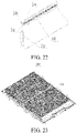
- An electric vehicle 1000 shown in FIG. 26 and FIG. 27 includes the foregoing battery pack 200 or the battery module 400.
- an endurance capability of the vehicle is higher, and costs are lower.
- connection may be a fixed connection, a detachable connection, or an integral connection; or the connection may be a mechanical connection or an electrical connection; or the connection may be a direct connection, an indirect connection through an intermediary, or internal communication between two components.
Landscapes
- Chemical & Material Sciences (AREA)
- Chemical Kinetics & Catalysis (AREA)
- Electrochemistry (AREA)
- General Chemical & Material Sciences (AREA)
- Engineering & Computer Science (AREA)
- Aviation & Aerospace Engineering (AREA)
- Connection Of Batteries Or Terminals (AREA)
- Battery Mounting, Suspending (AREA)
- Sealing Battery Cases Or Jackets (AREA)
- Secondary Cells (AREA)
Applications Claiming Priority (2)
| Application Number | Priority Date | Filing Date | Title |
|---|---|---|---|
| CN201911162027.XA CN112952244B (zh) | 2019-11-22 | 2019-11-22 | 一种电池、电池模组、电池包和电动车 |
| PCT/CN2020/130025 WO2021098761A1 (fr) | 2019-11-22 | 2020-11-19 | Batterie, module de batterie, bloc-batterie et véhicule électrique |
Publications (2)
| Publication Number | Publication Date |
|---|---|
| EP4050689A1 true EP4050689A1 (fr) | 2022-08-31 |
| EP4050689A4 EP4050689A4 (fr) | 2024-03-20 |
Family
ID=75980393
Family Applications (1)
| Application Number | Title | Priority Date | Filing Date |
|---|---|---|---|
| EP20890373.2A Pending EP4050689A4 (fr) | 2019-11-22 | 2020-11-19 | Batterie, module de batterie, bloc-batterie et véhicule électrique |
Country Status (6)
| Country | Link |
|---|---|
| US (1) | US20220416357A1 (fr) |
| EP (1) | EP4050689A4 (fr) |
| JP (1) | JP7450718B2 (fr) |
| KR (1) | KR102849582B1 (fr) |
| CN (1) | CN112952244B (fr) |
| WO (1) | WO2021098761A1 (fr) |
Cited By (1)
| Publication number | Priority date | Publication date | Assignee | Title |
|---|---|---|---|---|
| EP4152512A4 (fr) * | 2021-07-30 | 2023-11-08 | Contemporary Amperex Technology Co., Limited | Batterie, dispositif électrique et procédé de préparation de batterie |
Families Citing this family (16)
| Publication number | Priority date | Publication date | Assignee | Title |
|---|---|---|---|---|
| US12347832B2 (en) | 2013-09-18 | 2025-07-01 | Ambri, LLC | Electrochemical energy storage devices |
| CN109935747B (zh) | 2013-10-16 | 2022-06-07 | 安保瑞公司 | 用于高温反应性材料装置的密封件 |
| US12142735B1 (en) | 2013-11-01 | 2024-11-12 | Ambri, Inc. | Thermal management of liquid metal batteries |
| AU2019405440A1 (en) | 2018-12-17 | 2021-08-12 | Ambri, LLC | High temperature energy storage systems and methods |
| CN114361630A (zh) * | 2020-09-27 | 2022-04-15 | 比亚迪股份有限公司 | 一种电池、电池包和电动车 |
| CN113991226B (zh) * | 2021-11-19 | 2025-03-14 | 九环储能科技有限公司 | 组合式储能单体、储能簇及储能装置 |
| CN216720116U (zh) * | 2021-11-24 | 2022-06-10 | 比亚迪股份有限公司 | 电芯单元、电池及车辆 |
| CN114464961B (zh) * | 2022-01-19 | 2024-03-29 | 蜻蜓实验室(深圳)有限公司 | 锂离子电池及锂离子电池组 |
| WO2023147070A1 (fr) * | 2022-01-27 | 2023-08-03 | Ambri Inc. | Dispositifs de stockage d'énergie améliorés |
| CN118489186A (zh) * | 2022-08-09 | 2024-08-13 | 宁德时代新能源科技股份有限公司 | 端盖组件、电池组件、电池及用电设备 |
| CN115295936A (zh) * | 2022-09-02 | 2022-11-04 | 广汽埃安新能源汽车有限公司 | 转接桥结构、电池包及用电设备 |
| WO2024055304A1 (fr) * | 2022-09-16 | 2024-03-21 | 宁德时代新能源科技股份有限公司 | Batterie et dispositif électrique |
| CN115832552B (zh) * | 2022-10-20 | 2024-10-01 | 宁德时代新能源科技股份有限公司 | 电池单体和具有其的电池及用电装置 |
| CN116031112A (zh) * | 2023-01-09 | 2023-04-28 | 上海正泰智能科技有限公司 | 智能量测断路器 |
| CN119965427A (zh) * | 2023-11-09 | 2025-05-09 | 宁德时代新能源科技股份有限公司 | 电池单体、电池及用电装置 |
| CN118572296B (zh) * | 2024-08-01 | 2024-10-22 | 惠州市瑞能德电子有限公司 | 一种锂离子电池储能模组 |
Family Cites Families (19)
| Publication number | Priority date | Publication date | Assignee | Title |
|---|---|---|---|---|
| JP4395905B2 (ja) * | 1999-02-23 | 2010-01-13 | トヨタ自動車株式会社 | 集合電池およびその製造方法 |
| JP2001057202A (ja) * | 1999-06-07 | 2001-02-27 | Matsushita Electric Ind Co Ltd | 蓄電池 |
| WO2005119812A1 (fr) * | 2004-06-02 | 2005-12-15 | Sylva Industries Limited | Batterie prismatique dotee d'une nouvelle connexion intercellulaire |
| CN100429805C (zh) * | 2005-06-16 | 2008-10-29 | 比亚迪股份有限公司 | 一种电动车电池包 |
| CN201576715U (zh) * | 2010-01-06 | 2010-09-08 | 李辉 | 一种温控锂电池组 |
| JP5206711B2 (ja) * | 2010-03-05 | 2013-06-12 | トヨタ自動車株式会社 | 蓄電モジュールと該モジュール用枠体 |
| KR101136310B1 (ko) * | 2010-06-07 | 2012-04-19 | 에스비리모티브 주식회사 | 배터리 팩 |
| JPWO2012057323A1 (ja) * | 2010-10-30 | 2014-05-12 | 三洋電機株式会社 | 組電池及びこれを備える車両 |
| CN102104167A (zh) * | 2010-12-13 | 2011-06-22 | 湖南科力远新能源股份有限公司 | 具有内部串联式结构的电池组及其制作方法 |
| CN103430348A (zh) * | 2011-03-16 | 2013-12-04 | 丰田自动车株式会社 | 蓄电装置 |
| JP6087838B2 (ja) * | 2011-12-28 | 2017-03-01 | 三洋電機株式会社 | 電源装置、回路基板、及び電源装置を備える車両並びに蓄電装置 |
| US20140370345A1 (en) * | 2013-06-12 | 2014-12-18 | Motorola Mobility Llc | Segmented energy storage assembly |
| JP6315269B2 (ja) * | 2014-08-22 | 2018-04-25 | 株式会社デンソー | 密閉型電池モジュール及びその製造方法 |
| KR102032506B1 (ko) * | 2016-06-08 | 2019-10-15 | 주식회사 엘지화학 | 센싱 와이어 하네스의 접속 구조가 개선된 배터리 모듈 및 그 조립방법 |
| CN206490120U (zh) * | 2017-02-28 | 2017-09-12 | 宁德时代新能源科技股份有限公司 | 电池模组 |
| KR102187067B1 (ko) * | 2017-08-10 | 2020-12-04 | 주식회사 엘지화학 | 배터리 모듈 및 배터리 모듈의 제조 방법 |
| CN207967118U (zh) * | 2018-03-30 | 2018-10-12 | 宁德时代新能源科技股份有限公司 | 电池箱体以及电池箱 |
| KR102220898B1 (ko) * | 2018-10-17 | 2021-02-26 | 삼성에스디아이 주식회사 | 배터리 팩 |
| US11228070B2 (en) * | 2019-11-11 | 2022-01-18 | Ford Global Technologies, Llc | Efficient electric architectural layouts for electrified vehicles |
-
2019
- 2019-11-22 CN CN201911162027.XA patent/CN112952244B/zh active Active
-
2020
- 2020-11-19 EP EP20890373.2A patent/EP4050689A4/fr active Pending
- 2020-11-19 WO PCT/CN2020/130025 patent/WO2021098761A1/fr not_active Ceased
- 2020-11-19 KR KR1020227021330A patent/KR102849582B1/ko active Active
- 2020-11-19 JP JP2022529461A patent/JP7450718B2/ja active Active
- 2020-11-19 US US17/778,987 patent/US20220416357A1/en active Pending
Cited By (1)
| Publication number | Priority date | Publication date | Assignee | Title |
|---|---|---|---|---|
| EP4152512A4 (fr) * | 2021-07-30 | 2023-11-08 | Contemporary Amperex Technology Co., Limited | Batterie, dispositif électrique et procédé de préparation de batterie |
Also Published As
| Publication number | Publication date |
|---|---|
| CN112952244B (zh) | 2022-10-18 |
| JP7450718B2 (ja) | 2024-03-15 |
| CN112952244A (zh) | 2021-06-11 |
| KR20220104232A (ko) | 2022-07-26 |
| EP4050689A4 (fr) | 2024-03-20 |
| US20220416357A1 (en) | 2022-12-29 |
| KR102849582B1 (ko) | 2025-08-22 |
| WO2021098761A1 (fr) | 2021-05-27 |
| JP2023502691A (ja) | 2023-01-25 |
Similar Documents
| Publication | Publication Date | Title |
|---|---|---|
| EP4050689A1 (fr) | Batterie, module de batterie, bloc-batterie et véhicule électrique | |
| KR102734561B1 (ko) | 배터리, 배터리 모듈, 배터리 팩, 및 전기 자동차 | |
| CN211743203U (zh) | 一种电池、电池模组、电池包和电动车 | |
| CN211743281U (zh) | 一种电池、电池模组、电池包和电动车 | |
| EP3965202A1 (fr) | Batterie au lithium-ion, module de batterie, bloc-batterie et véhicule automobile | |
| EP2551940B1 (fr) | Batterie secondaire | |
| CN110518174A (zh) | 一种电池、电池模组、电池包和电动车 | |
| EP2899790A1 (fr) | Ensemble électrode, batterie le comprenant, et son procédé de fabrication | |
| CN103988331A (zh) | 具有超疏水材料的硬壳壳体 | |
| US20090081539A1 (en) | Battery pack | |
| KR102840824B1 (ko) | 배터리, 배터리 모듈, 배터리 팩, 및 전기 차량 | |
| KR20220139359A (ko) | 배터리, 배터리 모듈, 배터리 팩, 및 전기 차량 | |
| EP2642551B1 (fr) | Batterie secondaire | |
| KR20140101228A (ko) | 전지 모듈 | |
| KR100824865B1 (ko) | 이차전지 | |
| KR100839785B1 (ko) | 이차전지 및 그 형성 방법 | |
| US20110287289A1 (en) | Rechargeable battery and battery module | |
| KR100917751B1 (ko) | 팩형 이차전지 | |
| JP7420940B2 (ja) | 電池、電池モジュール、電池パック及び電気自動車 | |
| CN113258178B (zh) | 电池、电池模组、电池包及电动车 | |
| CN112838302B (zh) | 一种电池、电池模组、电池包和汽车 | |
| CN101404339B (zh) | 二次电池 | |
| KR20010046921A (ko) | 리튬 폴리머 전지팩 | |
| KR101329830B1 (ko) | 이차 전지 | |
| CN115803944B (zh) | 电化学装置及用电装置 |
Legal Events
| Date | Code | Title | Description |
|---|---|---|---|
| STAA | Information on the status of an ep patent application or granted ep patent |
Free format text: STATUS: THE INTERNATIONAL PUBLICATION HAS BEEN MADE |
|
| PUAI | Public reference made under article 153(3) epc to a published international application that has entered the european phase |
Free format text: ORIGINAL CODE: 0009012 |
|
| STAA | Information on the status of an ep patent application or granted ep patent |
Free format text: STATUS: REQUEST FOR EXAMINATION WAS MADE |
|
| 17P | Request for examination filed |
Effective date: 20220525 |
|
| AK | Designated contracting states |
Kind code of ref document: A1 Designated state(s): AL AT BE BG CH CY CZ DE DK EE ES FI FR GB GR HR HU IE IS IT LI LT LU LV MC MK MT NL NO PL PT RO RS SE SI SK SM TR |
|
| DAV | Request for validation of the european patent (deleted) | ||
| DAX | Request for extension of the european patent (deleted) | ||
| A4 | Supplementary search report drawn up and despatched |
Effective date: 20240219 |
|
| RIC1 | Information provided on ipc code assigned before grant |
Ipc: H01M 50/519 20210101ALI20240213BHEP Ipc: H01M 50/51 20210101ALI20240213BHEP Ipc: H01M 50/503 20210101ALI20240213BHEP Ipc: H01M 50/298 20210101ALI20240213BHEP Ipc: H01M 50/249 20210101ALI20240213BHEP Ipc: H01M 50/209 20210101ALI20240213BHEP Ipc: H01M 50/112 20210101ALI20240213BHEP Ipc: H01M 10/04 20060101AFI20240213BHEP |