EP4063253B1 - Bouée permettant de vérifier l'état d'une personne ou d'un objet attaché à ladite bouée - Google Patents
Bouée permettant de vérifier l'état d'une personne ou d'un objet attaché à ladite bouée Download PDFInfo
- Publication number
- EP4063253B1 EP4063253B1 EP21202308.9A EP21202308A EP4063253B1 EP 4063253 B1 EP4063253 B1 EP 4063253B1 EP 21202308 A EP21202308 A EP 21202308A EP 4063253 B1 EP4063253 B1 EP 4063253B1
- Authority
- EP
- European Patent Office
- Prior art keywords
- buoy
- anchor
- camera
- casing
- capsule
- Prior art date
- Legal status (The legal status is an assumption and is not a legal conclusion. Google has not performed a legal analysis and makes no representation as to the accuracy of the status listed.)
- Active
Links
Images


Classifications
-
- B—PERFORMING OPERATIONS; TRANSPORTING
- B63—SHIPS OR OTHER WATERBORNE VESSELS; RELATED EQUIPMENT
- B63B—SHIPS OR OTHER WATERBORNE VESSELS; EQUIPMENT FOR SHIPPING
- B63B22/00—Buoys
-
- A—HUMAN NECESSITIES
- A61—MEDICAL OR VETERINARY SCIENCE; HYGIENE
- A61B—DIAGNOSIS; SURGERY; IDENTIFICATION
- A61B5/00—Measuring for diagnostic purposes; Identification of persons
- A61B5/68—Arrangements of detecting, measuring or recording means, e.g. sensors, in relation to patient
- A61B5/6887—Arrangements of detecting, measuring or recording means, e.g. sensors, in relation to patient mounted on external non-worn devices, e.g. non-medical devices
-
- B—PERFORMING OPERATIONS; TRANSPORTING
- B63—SHIPS OR OTHER WATERBORNE VESSELS; RELATED EQUIPMENT
- B63B—SHIPS OR OTHER WATERBORNE VESSELS; EQUIPMENT FOR SHIPPING
- B63B21/00—Tying-up; Shifting, towing, or pushing equipment; Anchoring
- B63B21/20—Adaptations of chains, ropes, hawsers, or the like, or of parts thereof
-
- B—PERFORMING OPERATIONS; TRANSPORTING
- B63—SHIPS OR OTHER WATERBORNE VESSELS; RELATED EQUIPMENT
- B63B—SHIPS OR OTHER WATERBORNE VESSELS; EQUIPMENT FOR SHIPPING
- B63B27/00—Arrangement of ship-based loading or unloading equipment for cargo or passengers
- B63B27/18—Arrangement of ship-based loading or unloading equipment for cargo or passengers of cableways, e.g. with breeches-buoys
-
- B—PERFORMING OPERATIONS; TRANSPORTING
- B63—SHIPS OR OTHER WATERBORNE VESSELS; RELATED EQUIPMENT
- B63B—SHIPS OR OTHER WATERBORNE VESSELS; EQUIPMENT FOR SHIPPING
- B63B45/00—Arrangements or adaptations of signalling or lighting devices
- B63B45/04—Arrangements or adaptations of signalling or lighting devices the devices being intended to indicate the vessel or parts thereof
-
- B—PERFORMING OPERATIONS; TRANSPORTING
- B63—SHIPS OR OTHER WATERBORNE VESSELS; RELATED EQUIPMENT
- B63B—SHIPS OR OTHER WATERBORNE VESSELS; EQUIPMENT FOR SHIPPING
- B63B5/00—Hulls characterised by their construction of non-metallic material
- B63B5/24—Hulls characterised by their construction of non-metallic material made predominantly of plastics
-
- G—PHYSICS
- G01—MEASURING; TESTING
- G01S—RADIO DIRECTION-FINDING; RADIO NAVIGATION; DETERMINING DISTANCE OR VELOCITY BY USE OF RADIO WAVES; LOCATING OR PRESENCE-DETECTING BY USE OF THE REFLECTION OR RERADIATION OF RADIO WAVES; ANALOGOUS ARRANGEMENTS USING OTHER WAVES
- G01S19/00—Satellite radio beacon positioning systems; Determining position, velocity or attitude using signals transmitted by such systems
- G01S19/01—Satellite radio beacon positioning systems transmitting time-stamped messages, e.g. GPS [Global Positioning System], GLONASS [Global Orbiting Navigation Satellite System] or GALILEO
-
- H—ELECTRICITY
- H02—GENERATION; CONVERSION OR DISTRIBUTION OF ELECTRIC POWER
- H02S—GENERATION OF ELECTRIC POWER BY CONVERSION OF INFRARED RADIATION, VISIBLE LIGHT OR ULTRAVIOLET LIGHT, e.g. USING PHOTOVOLTAIC [PV] MODULES
- H02S10/00—PV power plants; Combinations of PV energy systems with other systems for the generation of electric power
- H02S10/40—Mobile PV generator systems
-
- H—ELECTRICITY
- H04—ELECTRIC COMMUNICATION TECHNIQUE
- H04N—PICTORIAL COMMUNICATION, e.g. TELEVISION
- H04N23/00—Cameras or camera modules comprising electronic image sensors; Control thereof
- H04N23/57—Mechanical or electrical details of cameras or camera modules specially adapted for being embedded in other devices
-
- H—ELECTRICITY
- H04—ELECTRIC COMMUNICATION TECHNIQUE
- H04N—PICTORIAL COMMUNICATION, e.g. TELEVISION
- H04N7/00—Television systems
- H04N7/18—Closed-circuit television [CCTV] systems, i.e. systems in which the video signal is not broadcast
- H04N7/183—Closed-circuit television [CCTV] systems, i.e. systems in which the video signal is not broadcast for receiving images from a single remote source
-
- B—PERFORMING OPERATIONS; TRANSPORTING
- B63—SHIPS OR OTHER WATERBORNE VESSELS; RELATED EQUIPMENT
- B63B—SHIPS OR OTHER WATERBORNE VESSELS; EQUIPMENT FOR SHIPPING
- B63B21/00—Tying-up; Shifting, towing, or pushing equipment; Anchoring
- B63B21/20—Adaptations of chains, ropes, hawsers, or the like, or of parts thereof
- B63B2021/203—Mooring cables or ropes, hawsers, or the like; Adaptations thereof
-
- B—PERFORMING OPERATIONS; TRANSPORTING
- B63—SHIPS OR OTHER WATERBORNE VESSELS; RELATED EQUIPMENT
- B63B—SHIPS OR OTHER WATERBORNE VESSELS; EQUIPMENT FOR SHIPPING
- B63B22/00—Buoys
- B63B2022/006—Buoys specially adapted for measuring or watch purposes
Definitions
- the present invention belongs to the nautical field, specifically to the field of buoys for tying vessels.
- the invention relates to a buoy for checking the condition of a person or an object tied to the said buoy.
- a buoy is a floating structure used for different purposes.
- Several different types of buoys are available: a communication buoy, a navigation buoy, a sonar buoy, a markation buoy, a weather buoy and a diving buoy, wherein they can be anchored or free-floating.
- a buoy can be used for marking vessel quays, especially outside marina. All buoys have a common characteristic - they mark a certain location, and they can emit and receive data important for navigation, measurements or communication.
- the technical problem, solved by the said invention is construction of a buoy, which will enable checking the condition of person or object fastened (tied or attached) to the said buoy.
- underwater drones or cameras such as described in the patent application US20050036031
- they must be monitored by the user at all times otherwise important data is lost in important moments.
- the preparation of currently known underwater drones is time-consuming. Additionally, they need to locate the desired object or the person in the water in order to allow monitoring. When the drone is back on land or on vessel the monitoring of the person or the object is lost.
- the camera, as described in the patent application US20050036031 is intended mostly for observing sea life and is connected via cable to a specific device, which requires continuous monitoring. It does not display the object's or person's position and it is very time-consuming for preparation. When the water depth is changing, it is also important to monitor and unwind the cable in order to maintain same position.
- the present invention solves listed shortcomings and disadvantages.
- the patent application US2015116496A1 describes an anchor, equipped with a camera, a sensor and a light.
- the system connected to the camera, sensor and light on the anchor guarantees anchor monitoring in real time and enables notifications regarding the anchor state.
- Patent US9729253 discloses a system with an underwater housing, which comprises an underwater wireless communication module, connected to the camera and an above-water housing with an above-water wire communication module, wherein both communication modules communicate via a cable. Camera captures photographs or video, which is forwarded via modules to a mobile device to monitor the conditions underwater.
- Patent application AU20141 00760A describes a safety buoy for use in marines, which has an electronic control unit and a radio transmitter that launches communication with the satellite network and sends out a distress call when activated with the electronic unit.
- Document AT517793 describes a device for optical control of water bodies, especially bodies underwater, the said device being provided with an attached buoy, wherein the rope of the buoy has a waterproof housing with installed cameras directed in all directions, along with a compass.
- the device can also include a sensor for determining camera position. An image can be captured with a trigger button via a transponder and suitable electronics.
- Patent application US5803780 discloses a buoy for marking, which can be used to simply mark a location at the sea bed.
- the buoy comprises a control mechanism, which releases a weight by using the optimal rope amount.
- Patent application US7034680 describes a device for monitoring anchor or anchor rope, which includes a measuring device, which uses one or more sensors to determine a status of one or more points on the anchor or the anchor rope with regards to the vessel and generates a signal to trigger an alarm when it deviates from the pre-set values.
- Patent application CA2088088 relates to a buoy for marking a location of an underwater object, especially a sunken vessel's anchor.
- a spherical buoy housing is connected via a nylon rope and an attachment to the anchor before it submerges.
- the length of the unwinding rope is controlled by a mechanism, so that the location of the buoy is not changed due to waves or other water movement, which enables reliable marking of the location of the anchor under water.
- the present invention differs from the above solutions in its construction.
- the essence of the buoy according to the invention is in that it comprises a casing, which floats on the water surface, a capsule with camera and lights, which can be separated from the casing with a UTP cable and lowered down to an anchor, an object or a person.
- the wire rope which is connected to the lower part of the capsule can be connected to any anchor, fixed object on the sea bed or it can be attached to a person (diver) with the wire rope.
- the camera captures images and/or video and sends data via UTP cable to the processor, and the processor emits data via wireless network (WiFi or similar) to the mobile application installed on the user device, which is preferably a smart phone, a tablet, computer or a similar device.
- the user can visually check the condition of the anchor and simultaneously monitor the anchor position via one or several satellite systems for global navigation (GNSS), e.g. GALILEO, GPS, GLONASS, BEIDOU, and the position is displayed graphically and numerically on an application on mobile telephone, tablet or computer.
- GNSS global navigation
- the buoy sends out images and video to the application, as well as telemetric data on battery condition, turning on and off the camera and lights, and sends out data to the server online or in a computer cloud, making the data, images and video available via any device connected to the internet.
- the buoy according to the invention comprises:
- the buoy casing is primarily made from ecologically processed, strong and resistant plastic mass, and both parts are assembled with threads and seals.
- the buoy is designed to preserve buoyancy even in case it submerges, because the watertight chamber for the key components in the buoy interior is an airtight sealed space and the air inside the buoy maintains it above water.
- the upper part of the buoy can be partially transparent and can additionally comprise signal lights in case of danger or anchor movement.
- the upper part may also comprise solar cells for charging the battery, which is installed in the waterproof chamber for key components, wherein the solar cells can be installed on the casing, but are preferably provided in the interior under the transparent material of the upper part of the casing.
- the lower part of the buoy has an opening at the bottom for the UTP/Ethernet cable.
- the bottom part of the buoy casing can have small holes at the bottom part, which enable draining of excess water, which remains in the buoy when lifted.
- the bottom part of the casing is designed to have a movable capsule with the camera and lights, or the casing is in its bottom part designed as a cavity, which can partially hide the capsule with the camera and lights.
- the capsule can be separated from the buoy casing by unwinding the cable using the rotating mechanism, which operates in such a manner that upon attaching a load on the wire rope the capsule is lowered due to gravity, while in case the load is removed from the wire rope the UTP cable is automatically wound on the reel due to the tensile spring, which is attached at the end of aluminium shaft in a fixed manner.
- the latter is attached to the two holders and together with the bushing enables the reel to be stable and attached in the interior of the buoy casing, wherein the bushing enable shaft rotation of the shaft without traction.
- the sliding bearing is made from highly resistant plastics and ensures mechanical stability with lowest coefficients of traction without additional greasing and is resistant to sea water.
- the spring is made from a coiled steel wire, and its coils enable stretching and automatic contraction.
- the UTP cable is automatically wound back on the reel.
- the pulling force must be higher than the force of the spring. This causes that the UTP cable is constantly tensed and that the buoy above the anchor is always in the same position above it. Even in the case of waves the spring is loosened and automatically winds the cable back to the reel.
- the holders of the aluminium shaft are attached with screws to the bottom part of the buoy casing, said holders being made from stainless steel.
- the watertight and/or waterproof chamber for key components for buoy operation is installed in the interior of the buoy casing, preferably the chamber of key components is made from two parts and the bottom part is with screws attached to the bottom part of the buoy casing, and the cover is tightly attached with screws and seals to the bottom part of the chamber of key components, which are the battery, the processor, the positioning module for determining geographic position with one or more systems GNSS, radio WiFi transmitter and receiver and a module for data transfer vial networks of mobile communication (LTE, 5G).
- LTE, 5G mobile communication
- On the inner part at the side of the chamber cover an opening is provided, through which the non-rotating part of the slide ring is installed, said non-rotating part leading the UTP cable from the processor via the rotating mechanism to the capsule.
- the watertight capsule is made from two parts, i.e. the upper part and bottom part of the capsule, which are connected to each other with screws and a seal.
- the bottom part from the internal side, has a space for the camera and lights, preferably which are preferably IR and LED lights.
- the bottom part has a suitably designed opening and sealed transparent part so that the camera can take images, while the lights emit light through the transparent material.
- the entire capsule is covered in rubber (except the opening for camera and lights), which absorbs hits and protects the plastic part of the capsule mould from external influences.
- the external part of the bottom part of the capsule has an attachment element for the wire rope, which can be approximately 2 m long, and its free end is provided with a ring or any other suitable element to which an anchor or any other object or a person in the water can be attached or tied.
- the camera in the capsule has the UTP cable that runs from the buoy casing, which fuels the camera with PoE (Power over Ethernet) electric current, which is used for sending image and video signal from the camera to the processor, which can send the data via WiFi to the application and via the module for data transfer via mobile network on the server.
- the camera is controlled via the cable with the processor and the application.
- the camera records in high resolution, and has an option of recording and saving individual photographs. All videos and images can be archived in the processor, the application and on a server.
- the camera enables visual control/monitoring of a certain object or a person underwater in real time.
- the camera has three modes of function.
- the camera functions as usually, and if only IR lights are on, it operates in a night mode, wherein the camera can operate even with lights off if the visibility is suitable and enough natural light is available.
- the lights are charged with the UTP cable, and their function is controlled with an application on mobile devices or remotely via the server.
- the application allows to choose turning on or off lights, which is communicated to the processor via a wireless connection, which forwards the information via the UTP cable to the camera in order to follow the processor commands.
- the camera is suitably connected to the lights so that it can adjust their function or light.
- the application performs the following steps:
- the application is used to set a geolocation, defined with a circle from 1 to 20 metres.
- a geolocation defined with a circle from 1 to 20 metres.
- the drawn circle of the limitation is displayed on the map, and any potential additional movement of the buoy is monitored by the positioning module after setting up the position. If the anchor leaves the pre-set circle limit the alarm s triggered, and the processor acts accordingly.
- the buoy efficiently monitors the anchor movement on its own, its movement and together with capturing images and/or video enables safer anchoring of any vessel in any water, preferably in the sea, where movements, waves and tide are important factors for movement of vessels and anchors.
- the process of using the buoy according to the invention comprises the following steps:
- the buoy according to the invention can be used to monitor underwater activity, especially on sea, lake or river bed. It is primarily intended for observing and monitoring the condition of the anchor, which is tied to the buoy, ensuring safe anchoring of the vessel anywhere in the sea, lake or river. Simultaneously, the buoy can be used to observe underwater life, a visual or image depiction of sea, lake or river bed. Nonetheless, the buoy according to the invention improves the safety of divers, since it can constantly monitor their dive and/or work and in case of problems ensures quick reactions.
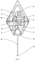
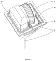
- FIG. 1 and 2 A possible embodiment of the buoy is shown Figures 1 and 2 and comprises:
- the buoy casing 8, 9 is made from ecologically processed, strong and resistant plastic mass, and both parts are assembled with threads and seals.
- the upper part 8 also comprises solar cells 18 for charging the battery, which is installed in the waterproof chamber 10 for key components 3, wherein the solar cells 18 are installed below the transparent material of the upper part 8 of the housing.
- the bottom part 9 of the buoy casing has an opening at the bottom, through which the UTP/Ethernet cable 2 runs, and at the same time the bottom part has a designed cavity to hide the capsule 12 with the camera 13 and lights 16, 17.
- the capsule 12 can be lowered as shown in Figure 3 , wherein it remains connected to the buoy with the UTP cable 2.
- Figure 4 displays the section of rotating mechanism, comprising:
- FIGS 5a and 5b in addition to the rotating mechanism also the capsule 12 and the chamber 10 are shown, while the non-rotating part of the slide ring is not visible.
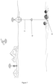
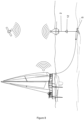
- Figures 6 to 8 show some possible ways of use, e.g. use of the buoy for marking location and monitoring the condition of a diver P, a location at sea bed D or an anchor S, which is used to anchor a vessel.
- the wire rope of the capsule 12 is tied or attached to the diver P, and the anchor S or wire rope is attached to the object at the sea bed, which causes separation on the capsule 12 from rest of the buoy, i.e. the capsule 12 is located lower than the buoy floating on the water surface.
- the UTP cable 2, which connects the buoy with the lowered capsule 12 enables transfer of energy for operation of the camera and lights as well as data transfer of capturing images or video with camera, and also for controlling the components of the capsule 12.
Landscapes
- Engineering & Computer Science (AREA)
- Chemical & Material Sciences (AREA)
- Ocean & Marine Engineering (AREA)
- Mechanical Engineering (AREA)
- Combustion & Propulsion (AREA)
- Life Sciences & Earth Sciences (AREA)
- Health & Medical Sciences (AREA)
- Physics & Mathematics (AREA)
- Remote Sensing (AREA)
- Radar, Positioning & Navigation (AREA)
- Signal Processing (AREA)
- Multimedia (AREA)
- Biomedical Technology (AREA)
- Molecular Biology (AREA)
- Biophysics (AREA)
- Pathology (AREA)
- General Physics & Mathematics (AREA)
- Heart & Thoracic Surgery (AREA)
- Medical Informatics (AREA)
- Computer Networks & Wireless Communication (AREA)
- Surgery (AREA)
- Animal Behavior & Ethology (AREA)
- General Health & Medical Sciences (AREA)
- Public Health (AREA)
- Veterinary Medicine (AREA)
- Studio Devices (AREA)
- Position Fixing By Use Of Radio Waves (AREA)
Claims (13)
- Une bouée permettant de vérifier l'état d'une personne ou d'un objet attaché à ladite bouée, celle-ci comprenant :- une enveloppe (8, 9), qui est conçue pour flotter sur la surface de la mer, et- une capsule (12) équipée d'une caméra (15) et de lampes (16, 17), qui peut être séparée de l'enveloppe (8, 9) avec un câble UTP (2) et est conçue pour être descendue en direction d'une ancre, d'un objet ou d'une personne, où le câble (2) se déroule et s'enroule par le biais d'un mécanisme rotatif, qui comprend une bague coulissante (1) possédant une partie pivotante et une partie non-pivotante qui permettent le déroulement du câble UTP (2), qui assure le transfert sans faille de l'énergie électrique et du signal vidéo via le câble UTP (2) depuis une caméra (15) jusqu'à un compartiment imperméable et/ou étanche (10) pour le logement des composants clés (3) et inversement,où la caméra (15) est conçue pour prendre des photos et/ou des vidéos et envoyer les données via le câble UTP (2) à un processeur, ledit processeur étant conçu pour envoyer des données par le biais d'un réseau sans fil (WiFi ou similaire) à une application mobile installée sur l'appareil de l'utilisateur, qui est de préférence un smartphone, une tablette, un ordinateur ou un appareil similaire,caractérisée par le fait que :- l'enveloppe (8, 9) comprend :∘ une partie supérieure (8) ayant la forme d'une pyramide et étant pourvue de cellules photovoltaïques (18) pour fournir de l'énergie permettant le fonctionnement, et∘ une partie inférieure (9) ayant la forme d'une pyramide tronquée ;- à l'intérieur de l'enveloppe (8,9) est installé le compartiment imperméable et/ou étanche (10) pour les composants clés (3) permettant le fonctionnement de la bouée, où à l'intérieur du compartiment, une batterie, un processeur, un module de positionnement pour la détermination de la position géographique par le biais d'un ou plusieurs systèmes mondiaux de navigation par satellite (GNSS, p.ex. GALILEO, GPS, GLONAS, BEIDOU), un émetteur et un récepteur de signal WiFi et un module de transfert de données par le biais d'un réseau de communication mobile (p.ex. LTE, 5G) sont installés ;- la partie inférieure (9) de l'enveloppe de la bouée possède une ouverture sur le dessous, par laquelle le câble UTP/Ethernet (2) passe, et la partie inférieure (9) est conçue pour permettre l'installation de la capsule amovible (12) équipée de la caméra (15) et des lampes (16, 17) ; ou alors l'enveloppe (9) est dans sa partie inférieure conçue comme une cavité, qui peut au moins partiellement contenir la capsule (12) équipée de la caméra (15) et des lampes (16, 17) ;- le câble UTP/Ethernet (2), qui raccorde la capsule (12) à l'enveloppe de la bouée, et est raccordé au processeur, où le câble (2) se déroule et s'enroule à l'aide d'un mécanisme rotatif installé de façon contiguë au compartiment (10), ledit mécanisme rotatif comprenant :∘ un enrouleur, installé sur une tige d'aluminium (6), qui fait office d'axe de rotation, sur lequel est installé un câble UTP (2), où la tige en aluminium (6) est installée dans l'enveloppe au moyen de pylônes (19) jusqu'à la bague coulissante (1) ;∘ la bague coulissante (1), qui se compose d'une partie rotative et d'une partie non rotative, et qui est disposée de façon à recevoir un cercle électrique allant de la batterie jusqu'à la capsule (12) et un signal vidéo provenant de la caméra (15) et dirigé vers le processeur, où le câble UTP (2) est installé au moyen de la tige en aluminium (6) à la partie rotative de la bague coulissante (1), et par le biais de glisseurs présents dans la bague coulissante (1) à la partie non rotative de la bague coulissante, installée dans le compartiment (10) ;∘ une douille (5) ou un palier coulissant installée sur la tige en aluminium (6) pour garantir une rotation fluide de ladite tige, et∘ des ressorts de traction rétractables (7), qui permettent le déroulement et l'enroulement automatique du câble UTP (2) sur l'enrouleur ;- un câble métallique (13) fixé sur la partie inférieure de la capsule (12), et la partie libre du câble métallique (13) est équipée d'un cerceau pour se fixer à une ancre (S) ou tout autre objet (D) ou personne (P).
- La bouée selon la revendication 1, caractérisée par le fait que le module de positionnement est un ou plusieurs systèmes mondiaux de navigation par satellite (GNSS), sélectionné dans le groupe comprenant GALILEO, GPS, GLONAS, BEIDOU et toute combinaison de ceux-ci.
- La bouée selon l'une quelconque des revendications précédentes, caractérisée par le fait que l'enveloppe (8, 9) de la bouée est constituée d'une matière plastique résistante, robuste et produite de façon écologique, et par le fait que les deux parties (8,9) de l'enveloppe sont assemblées avec des fils et des joints d'étanchéité.
- La bouée selon l'une quelconque des revendications précédentes, caractérisée par le fait que la partie supérieure (8) de la bouée est partiellement transparente et peut en outre comprendre des feux de signalisation en cas de danger ou de mouvement de l'ancre, et par le fait que les cellules photovoltaïques (18) peuvent être installées sur l'enveloppe, de préférence les cellules photovoltaïques (18) sont installées à l'intérieur de l'enveloppe sous le matériau transparent de la partie supérieure (8) de l'enveloppe.
- La bouée selon l'une quelconque des revendications précédentes, caractérisée par le fait que la capsule (12) peut être séparée de l'enveloppe de la bouée (8, 9) en déroulant le câble (2) avec le mécanisme rotatif, qui agit en se fixant au poids du câble métallique (13), et en raison de la gravité, la capsule (12) se déplace vers le bas en déroulant le câble (2), alors que quand le poids est retiré du câble métallique (13), le câble (2) s'enroule automatiquement sur l'enrouleur en raison de l'action du ressort de traction (7), qui est fixé à l'extrémité de la tige en aluminium (6), elle-même fixée aux deux pylônes (19), et permet, à l'aide de la douille (5), à l'enrouleur d'être stable et fixé à l'intérieur de l'enveloppe de la bouée, et la douille (6) permet la rotation de la tige sans traction, et l'extrémité de la tige en aluminium est fixée au palier coulissant, et l'autre partie est fixée au ressort rétractable (7) avec une force constante, celui-ci étant constitué d'une spirale de feuillard en acier, et la spirale du ressort permet l'étirement et la contraction automatiques.
- La bouée selon l'une quelconque des revendications précédentes, caractérisée par le fait que le compartiment imperméable et/ou étanche (10) pour les composants clés du fonctionnement de la bouée est installé à l'intérieur de l'enveloppe de la bouée, et pour l'essentiel le compartiment (10) pour les composants clés est constitué de deux parties, et la partie inférieure (11) dotée de vis est enroulée dans la partie inférieure (9) de l'enveloppe de la bouée, et le couvercle est fixé hermétiquement avec des vis et des joints d'étanchéité à la partie inférieure du compartiment des composants clés tels que la batterie, le processeur, le module de positionnement pour déterminer la position géographique par le biais d'un ou plusieurs systèmes GALILEO, GPS, et/ou GLONAS, un émetteur et récepteur de signal WiFi et un module pour le transfert des données via des réseaux de communication mobile (LTE, 5G), et la partie intérieure près du côté du couvercle du compartiment possède une ouverture, qui a une partie non-rotative de la bague coulissante (1), qui fait passer le câble UTP (2) depuis le processeur via le mécanisme de rotation jusqu'à la capsule (12).
- La bouée selon l'une quelconque des revendications précédentes, caractérisée par le fait que la capsule étanche (12) est composée d'une partie supérieure et d'une partie inférieure (12), qui sont assemblées avec des vis et un joint d'étanchéité, où la partie inférieure possède une ouverture de conception appropriée et une partie transparente étanche pour que la caméra (15) puisse prendre des photos, tandis que les lampes (16, 17) émettent de la lumière à travers le matériau transparent.
- La bouée selon l'une quelconque des revendications précédentes, caractérisée par le fait que l'intégralité de la capsule (12), sauf l'ouverture pour la caméra (15) et les lampes (16, 17), est recouverte de caoutchouc qui absorbe les chocs et protège la partie en plastique de la coque de la capsule (12) des facteurs extérieurs.
- La bouée selon l'une quelconque des revendications précédentes, caractérisée par le fait qu'elle est conçue de façon à utiliser le processeur et l'application pour contrôler la caméra (15) par le biais du câble UTP (2), ladite caméra (15) permettant le contrôle/suivi visuel d'un certain objet (S, D) ou d'une personne (P) sous l'eau en temps réel, où tous les enregistrements et images peuvent être archivés dans le processeur, l'application et sur un serveur.
- La bouée selon l'une quelconque des revendications qui précèdent, caractérisée par le fait que la caméra a trois modes de fonctionnement :- si les lampes LED (17) sont allumées, la caméra (15) fonctionne normalement,- si seules les lampes IR (16) sont allumées, la caméra (15) fonctionne en mode nocturne,- la caméra (15) fonctionne même quand les lumières sont éteintes, si la visibilité est appropriée et qu'il y a suffisamment de lumière naturelle.
- La bouée selon l'une quelconque des revendications qui précèdent, caractérisée par le fait que l'application effectue au moins les étapes suivantes :- affiche une visualisation vidéo ou en images de l'ancre (S),- affiche la localisation de l'ancre (S) sur la carte,- permet d'ajuster la lumière (16, 17) et la caméra (15) sur la bouée comme décrit ci-dessus,- permet le gardiennage virtuel de l'ancre (S) de 1 à 20 mètres, ce qui signifie que si l'ancre (S) dépasse les limites pré-établies, l'alarme se déclenche, prévenant l'utilisateur que l'ancre est passée en dehors de la zone définie, l'alarme pouvant être sonore, visuelle ou de tout type approprié et- elle archive les images et les vidéos en les stockant sur le serveur approprié.
- La bouée selon l'une quelconque des revendications précédentes, caractérisée par le fait que l'application est conçue de façon à ce que pour l'utilisation préférée de la bouée dans le suivi de l'état de l'ancre (S) et le gardiennage de l'ancre (S) au même endroit, l'application est utilisée pour définir un emplacement géographique, établissant ainsi un cercle d'un rayon allant de 1 à 20 mètres, où à partir du moment où la position est définie, celle-ci est archivée par le module de positionnement, et le gardiennage est mis en oeuvre par un logiciel avec le processeur, traçant ainsi un cercle de délimitation sur la carte, où tout mouvement ultérieur potentiel de la bouée est suivi par le module de positionnement après la configuration de la position, et où dans le cas où l'ancre franchit la limite que constitue le cercle prédéfini, l'alarme est conçue pour être déclenchée, où le processeur est conçu pour agir en conséquence.
- Un procédé d'utilisation de la bouée selon l'une quelconque des revendications précédentes, ledit procédé comprenant les étapes suivantes :a) l'enregistrement dans une application avec un nom d'utilisateur et un mot de passe ;b) la connexion à la bouée ou à une bouée donnée, s'il y en a plusieurs, et nommage de la bouée ;c) l'affichage de la localisation de la bouée sur la carte ;d) la connexion à une ancre (S) ou un objet (D) ou une personne (P) attachée à la bouée et descente dans l'eau, ce qui provoque la descente ou le déroulement automatique du câble depuis la bouée ;e) une fois l'ancre (S) ou l'objet (D) ou la personne (P) placée sur le fond marin ou à une certaine profondeur, le déroulement s'arrête ou repart en sens inverse puis redescend au moyen du système d'enroulement automatique si besoin est, en fonction des vagues ou du mouvement de l'ancre ou de l'objet ;f) facultativement, l'activation de la lumière et la saisie d'images ou d'une vidéo de l'objet relié à la bouée ;g) l'affichage de l'image ou de la vidéo avec la possibilité de gérer et d'ajuster les lampes (IR, LED et de haute intensité) ainsi que décrit ci-dessus ;h) facultativement, la possibilité d'améliorer et d'archiver les images sur le smartphone et accès à la galerie ;i) définition facultative de limites géographiques (gardiennage virtuel) allant de 1 à 20 mètres, en traçant un cercle autour de la position de la bouée ;j) déclenchement possible de l'alarme quand l'ancre franchit la limite du cercle défini ;k) facultativement, extinction de la caméra (15) et/ou des lampes (16, 17) ;l) facultativement, levage de l'ancre ou de l'objet du fond marin vers la surface de l'eau, ce qui est réalisé en enroulant automatiquement le câble UTP (2) à l'aide du système d'enroulement automatique (7) ; etm) extraction de la bouée hors de l'eau.
Applications Claiming Priority (1)
| Application Number | Priority Date | Filing Date | Title |
|---|---|---|---|
| SI202100061A SI26157A (sl) | 2021-03-26 | 2021-03-26 | Boja za preverjanje stanja osebe ali predmeta vezanega na omenjeno bojo |
Publications (3)
| Publication Number | Publication Date |
|---|---|
| EP4063253A1 EP4063253A1 (fr) | 2022-09-28 |
| EP4063253B1 true EP4063253B1 (fr) | 2024-08-14 |
| EP4063253C0 EP4063253C0 (fr) | 2024-08-14 |
Family
ID=78819226
Family Applications (1)
| Application Number | Title | Priority Date | Filing Date |
|---|---|---|---|
| EP21202308.9A Active EP4063253B1 (fr) | 2021-03-26 | 2021-10-12 | Bouée permettant de vérifier l'état d'une personne ou d'un objet attaché à ladite bouée |
Country Status (3)
| Country | Link |
|---|---|
| US (1) | US20220306245A1 (fr) |
| EP (1) | EP4063253B1 (fr) |
| SI (1) | SI26157A (fr) |
Families Citing this family (8)
| Publication number | Priority date | Publication date | Assignee | Title |
|---|---|---|---|---|
| CN115285293B (zh) * | 2022-10-08 | 2023-01-17 | 国家深海基地管理中心 | 一种用于深海锚系快速回收的智能无人船 |
| KR102887095B1 (ko) * | 2023-07-18 | 2025-11-17 | 주식회사 지앤씨에너지 | 저수지 수위 측정기 |
| KR102635188B1 (ko) * | 2023-09-19 | 2024-02-08 | 주식회사 이도 | 부유식 수위 계측장치를 이용한 저수지 수위 모니터링 시스템 |
| KR102635187B1 (ko) * | 2023-09-19 | 2024-02-08 | 주식회사 이도 | 부유식 수위 계측장치 |
| CN118323356B (zh) * | 2024-06-14 | 2024-08-30 | 中国海洋大学 | 一种用于海洋装备清污探伤的无人船及其作业方法 |
| CN119590561B (zh) * | 2024-11-22 | 2025-11-07 | 宜昌测试技术研究所 | 一种自适应型通讯浮标 |
| CN119284046B (zh) * | 2024-12-13 | 2025-02-14 | 中国船舶集团有限公司第七六O研究所 | 一种海洋环境监测浮标平台 |
| CN120840808B (zh) * | 2025-09-25 | 2025-12-02 | 中国极地研究中心(中国极地研究所) | 一种适用于科考船的浮标回收装置 |
Family Cites Families (15)
| Publication number | Priority date | Publication date | Assignee | Title |
|---|---|---|---|---|
| CA2088088A1 (fr) | 1993-01-26 | 1994-07-27 | Andrew M. Tkachenko | Bouee servant a signaler la presence d'ancres de bateau submergees |
| US6057879A (en) | 1996-03-11 | 2000-05-02 | Weber; Eric D. | Fishing surveillance device |
| US5803780A (en) | 1996-03-19 | 1998-09-08 | Gutierrez, Jr.; Salvadore | Marker buoy with self-adjusting integral reel |
| DE19716684B4 (de) | 1997-04-21 | 2009-11-26 | Deep Blue Technology Ag | Anker-/Ankerketten-Überwachungsvorrichtung |
| US6036499A (en) * | 1998-06-22 | 2000-03-14 | Walker Downriggers, Inc. | Electrical connector for a cable reel |
| US6383045B1 (en) * | 2001-04-21 | 2002-05-07 | Ronald Eckardt | Marker buoy |
| SI22933A (sl) | 2010-02-02 | 2010-06-30 | SKLAD@NEPREMIÄŚNIN@d@o@o | Sestav za samodejno upravljanje in nadzor nad uporabo privezov za vodna plovila ki vključuje avtomatizirane plavajoče boje ter metoda v zvezi s tem |
| AU2014100760A4 (en) | 2011-10-14 | 2014-07-24 | Rip Buoy Holdings Limited | Safety buoy |
| US20150116496A1 (en) | 2013-10-29 | 2015-04-30 | Ottarr, Llc | Camera, Sensor and/or Light-Equipped Anchor |
| US9463849B2 (en) * | 2014-02-20 | 2016-10-11 | Woods Hole Oceanographic Institution | Mechanical tether system for a submersible vehicle |
| US9729253B2 (en) | 2014-10-24 | 2017-08-08 | Wahoo Technologies, LLC | System and method for providing underwater video |
| AT517793A2 (de) | 2015-07-10 | 2017-04-15 | Hois Ralph | Anordnung zur optischen Überwachung von Gewässern |
| US20180001981A1 (en) * | 2016-06-20 | 2018-01-04 | Fathom Drones, Inc. | Underwater remotely operated vehicle |
| WO2019113137A2 (fr) * | 2017-12-04 | 2019-06-13 | Gordon John Taylor Ii | Systèmes de navire d'exploration maritime de récupération et de transmission de données |
| CN110203333B (zh) * | 2019-06-03 | 2020-10-27 | 中国科学院南海海洋研究所 | 基于北斗铱星双星通信的海-气耦合实时观测浮标系统 |
-
2021
- 2021-03-26 SI SI202100061A patent/SI26157A/sl active IP Right Grant
- 2021-10-12 EP EP21202308.9A patent/EP4063253B1/fr active Active
-
2022
- 2022-03-26 US US17/705,280 patent/US20220306245A1/en active Pending
Also Published As
| Publication number | Publication date |
|---|---|
| SI26157A (sl) | 2022-09-30 |
| EP4063253A1 (fr) | 2022-09-28 |
| US20220306245A1 (en) | 2022-09-29 |
| EP4063253C0 (fr) | 2024-08-14 |
Similar Documents
| Publication | Publication Date | Title |
|---|---|---|
| EP4063253B1 (fr) | Bouée permettant de vérifier l'état d'une personne ou d'un objet attaché à ladite bouée | |
| CN208360444U (zh) | 一种无人船及系统 | |
| KR101736381B1 (ko) | 자동 윈치를 탑재한 드론을 이용한 실시간 원격 해양관측 방법 | |
| CN108189969B (zh) | 一种基于卫星通讯数据实时传输的深海锚系潜标系统 | |
| JP3854984B1 (ja) | ブイおよびこのブイを用いた海洋環境モニタシステム | |
| KR101858845B1 (ko) | 어구통합관리시스템 | |
| KR101710613B1 (ko) | 수중익을 구비한 수중드론을 이용한 실시간 파랑-유속 관측방법 및 그 장치 | |
| CN108216492A (zh) | 一种实现海洋数据区域监测的高精度潜标阵系统 | |
| KR101936912B1 (ko) | 해빈류 장기 관측 시스템 | |
| US20160090160A1 (en) | Underwater mobile body | |
| US20110138675A1 (en) | Radio controlled fish finding lure float | |
| CA2997440A1 (fr) | Bouee intelligente | |
| US20100197181A1 (en) | Underwater buoy system | |
| Turchik et al. | The Deep Ocean Dropcam: a highly deployable benthic survey tool | |
| CN109178212B (zh) | 一种测量水平剖面流场的系留潜标 | |
| WO2003062044A1 (fr) | Procede et appareil destines a surveiller des conditions sous-marines | |
| JPH1020382A (ja) | 水中観察装置 | |
| KR20210073320A (ko) | 드론용 도킹 시스템 | |
| US20240367755A1 (en) | Underwater retrieval device and rewinding systems | |
| JPH09211340A (ja) | 水中観察装置 | |
| KR102924651B1 (ko) | 드론을 이용한 해양환경 감시 시스템 | |
| KR102959622B1 (ko) | 항공기 및 선박 투하용 표류경로 추적 부이 | |
| KR102773044B1 (ko) | 갯벌이용자 위치추적 모니터링 시스템 | |
| KR102385248B1 (ko) | 서보모터를 이용한 소형 스마트 윈치 | |
| RU191164U1 (ru) | Устройство для дистанционной фоторегистрации |
Legal Events
| Date | Code | Title | Description |
|---|---|---|---|
| PUAI | Public reference made under article 153(3) epc to a published international application that has entered the european phase |
Free format text: ORIGINAL CODE: 0009012 |
|
| STAA | Information on the status of an ep patent application or granted ep patent |
Free format text: STATUS: THE APPLICATION HAS BEEN PUBLISHED |
|
| AK | Designated contracting states |
Kind code of ref document: A1 Designated state(s): AL AT BE BG CH CY CZ DE DK EE ES FI FR GB GR HR HU IE IS IT LI LT LU LV MC MK MT NL NO PL PT RO RS SE SI SK SM TR |
|
| STAA | Information on the status of an ep patent application or granted ep patent |
Free format text: STATUS: REQUEST FOR EXAMINATION WAS MADE |
|
| 17P | Request for examination filed |
Effective date: 20230326 |
|
| RBV | Designated contracting states (corrected) |
Designated state(s): AL AT BE BG CH CY CZ DE DK EE ES FI FR GB GR HR HU IE IS IT LI LT LU LV MC MK MT NL NO PL PT RO RS SE SI SK SM TR |
|
| GRAP | Despatch of communication of intention to grant a patent |
Free format text: ORIGINAL CODE: EPIDOSNIGR1 |
|
| STAA | Information on the status of an ep patent application or granted ep patent |
Free format text: STATUS: GRANT OF PATENT IS INTENDED |
|
| INTG | Intention to grant announced |
Effective date: 20240314 |
|
| GRAS | Grant fee paid |
Free format text: ORIGINAL CODE: EPIDOSNIGR3 |
|
| GRAA | (expected) grant |
Free format text: ORIGINAL CODE: 0009210 |
|
| STAA | Information on the status of an ep patent application or granted ep patent |
Free format text: STATUS: THE PATENT HAS BEEN GRANTED |
|
| AK | Designated contracting states |
Kind code of ref document: B1 Designated state(s): AL AT BE BG CH CY CZ DE DK EE ES FI FR GB GR HR HU IE IS IT LI LT LU LV MC MK MT NL NO PL PT RO RS SE SI SK SM TR |
|
| REG | Reference to a national code |
Ref country code: GB Ref legal event code: FG4D |
|
| REG | Reference to a national code |
Ref country code: CH Ref legal event code: EP |
|
| REG | Reference to a national code |
Ref country code: DE Ref legal event code: R096 Ref document number: 602021017123 Country of ref document: DE |
|
| REG | Reference to a national code |
Ref country code: IE Ref legal event code: FG4D |
|
| U01 | Request for unitary effect filed |
Effective date: 20240905 |
|
| U07 | Unitary effect registered |
Designated state(s): AT BE BG DE DK EE FI FR IT LT LU LV MT NL PT RO SE SI Effective date: 20240923 |
|
| U20 | Renewal fee for the european patent with unitary effect paid |
Year of fee payment: 4 Effective date: 20241028 |
|
| PG25 | Lapsed in a contracting state [announced via postgrant information from national office to epo] |
Ref country code: NO Free format text: LAPSE BECAUSE OF FAILURE TO SUBMIT A TRANSLATION OF THE DESCRIPTION OR TO PAY THE FEE WITHIN THE PRESCRIBED TIME-LIMIT Effective date: 20241114 |
|
| PG25 | Lapsed in a contracting state [announced via postgrant information from national office to epo] |
Ref country code: PL Free format text: LAPSE BECAUSE OF FAILURE TO SUBMIT A TRANSLATION OF THE DESCRIPTION OR TO PAY THE FEE WITHIN THE PRESCRIBED TIME-LIMIT Effective date: 20240814 Ref country code: GR Free format text: LAPSE BECAUSE OF FAILURE TO SUBMIT A TRANSLATION OF THE DESCRIPTION OR TO PAY THE FEE WITHIN THE PRESCRIBED TIME-LIMIT Effective date: 20241115 |
|
| PG25 | Lapsed in a contracting state [announced via postgrant information from national office to epo] |
Ref country code: IS Free format text: LAPSE BECAUSE OF FAILURE TO SUBMIT A TRANSLATION OF THE DESCRIPTION OR TO PAY THE FEE WITHIN THE PRESCRIBED TIME-LIMIT Effective date: 20241214 |
|
| PG25 | Lapsed in a contracting state [announced via postgrant information from national office to epo] |
Ref country code: HR Free format text: LAPSE BECAUSE OF FAILURE TO SUBMIT A TRANSLATION OF THE DESCRIPTION OR TO PAY THE FEE WITHIN THE PRESCRIBED TIME-LIMIT Effective date: 20240814 |
|
| PG25 | Lapsed in a contracting state [announced via postgrant information from national office to epo] |
Ref country code: RS Free format text: LAPSE BECAUSE OF FAILURE TO SUBMIT A TRANSLATION OF THE DESCRIPTION OR TO PAY THE FEE WITHIN THE PRESCRIBED TIME-LIMIT Effective date: 20241114 Ref country code: ES Free format text: LAPSE BECAUSE OF FAILURE TO SUBMIT A TRANSLATION OF THE DESCRIPTION OR TO PAY THE FEE WITHIN THE PRESCRIBED TIME-LIMIT Effective date: 20240814 |
|
| PG25 | Lapsed in a contracting state [announced via postgrant information from national office to epo] |
Ref country code: RS Free format text: LAPSE BECAUSE OF FAILURE TO SUBMIT A TRANSLATION OF THE DESCRIPTION OR TO PAY THE FEE WITHIN THE PRESCRIBED TIME-LIMIT Effective date: 20241114 Ref country code: PL Free format text: LAPSE BECAUSE OF FAILURE TO SUBMIT A TRANSLATION OF THE DESCRIPTION OR TO PAY THE FEE WITHIN THE PRESCRIBED TIME-LIMIT Effective date: 20240814 Ref country code: NO Free format text: LAPSE BECAUSE OF FAILURE TO SUBMIT A TRANSLATION OF THE DESCRIPTION OR TO PAY THE FEE WITHIN THE PRESCRIBED TIME-LIMIT Effective date: 20241114 Ref country code: IS Free format text: LAPSE BECAUSE OF FAILURE TO SUBMIT A TRANSLATION OF THE DESCRIPTION OR TO PAY THE FEE WITHIN THE PRESCRIBED TIME-LIMIT Effective date: 20241214 Ref country code: HR Free format text: LAPSE BECAUSE OF FAILURE TO SUBMIT A TRANSLATION OF THE DESCRIPTION OR TO PAY THE FEE WITHIN THE PRESCRIBED TIME-LIMIT Effective date: 20240814 Ref country code: GR Free format text: LAPSE BECAUSE OF FAILURE TO SUBMIT A TRANSLATION OF THE DESCRIPTION OR TO PAY THE FEE WITHIN THE PRESCRIBED TIME-LIMIT Effective date: 20241115 Ref country code: ES Free format text: LAPSE BECAUSE OF FAILURE TO SUBMIT A TRANSLATION OF THE DESCRIPTION OR TO PAY THE FEE WITHIN THE PRESCRIBED TIME-LIMIT Effective date: 20240814 |
|
| PG25 | Lapsed in a contracting state [announced via postgrant information from national office to epo] |
Ref country code: SM Free format text: LAPSE BECAUSE OF FAILURE TO SUBMIT A TRANSLATION OF THE DESCRIPTION OR TO PAY THE FEE WITHIN THE PRESCRIBED TIME-LIMIT Effective date: 20240814 |
|
| PG25 | Lapsed in a contracting state [announced via postgrant information from national office to epo] |
Ref country code: CZ Free format text: LAPSE BECAUSE OF FAILURE TO SUBMIT A TRANSLATION OF THE DESCRIPTION OR TO PAY THE FEE WITHIN THE PRESCRIBED TIME-LIMIT Effective date: 20240814 |
|
| PG25 | Lapsed in a contracting state [announced via postgrant information from national office to epo] |
Ref country code: SK Free format text: LAPSE BECAUSE OF FAILURE TO SUBMIT A TRANSLATION OF THE DESCRIPTION OR TO PAY THE FEE WITHIN THE PRESCRIBED TIME-LIMIT Effective date: 20240814 |
|
| REG | Reference to a national code |
Ref country code: CH Ref legal event code: PL |
|
| PLBE | No opposition filed within time limit |
Free format text: ORIGINAL CODE: 0009261 |
|
| STAA | Information on the status of an ep patent application or granted ep patent |
Free format text: STATUS: NO OPPOSITION FILED WITHIN TIME LIMIT |
|
| PG25 | Lapsed in a contracting state [announced via postgrant information from national office to epo] |
Ref country code: MC Free format text: LAPSE BECAUSE OF FAILURE TO SUBMIT A TRANSLATION OF THE DESCRIPTION OR TO PAY THE FEE WITHIN THE PRESCRIBED TIME-LIMIT Effective date: 20240814 |
|
| 26N | No opposition filed |
Effective date: 20250515 |
|
| PG25 | Lapsed in a contracting state [announced via postgrant information from national office to epo] |
Ref country code: CH Free format text: LAPSE BECAUSE OF NON-PAYMENT OF DUE FEES Effective date: 20241031 |
|
| PG25 | Lapsed in a contracting state [announced via postgrant information from national office to epo] |
Ref country code: IE Free format text: LAPSE BECAUSE OF NON-PAYMENT OF DUE FEES Effective date: 20241012 |
|
| PG25 | Lapsed in a contracting state [announced via postgrant information from national office to epo] |
Ref country code: CY Free format text: LAPSE BECAUSE OF FAILURE TO SUBMIT A TRANSLATION OF THE DESCRIPTION OR TO PAY THE FEE WITHIN THE PRESCRIBED TIME-LIMIT; INVALID AB INITIO Effective date: 20211012 |
|
| PG25 | Lapsed in a contracting state [announced via postgrant information from national office to epo] |
Ref country code: HU Free format text: LAPSE BECAUSE OF FAILURE TO SUBMIT A TRANSLATION OF THE DESCRIPTION OR TO PAY THE FEE WITHIN THE PRESCRIBED TIME-LIMIT; INVALID AB INITIO Effective date: 20211012 |
|
| U21 | Renewal fee for the european patent with unitary effect paid with additional fee |
Year of fee payment: 5 Effective date: 20260310 |