EP4065420B1 - Système d'affichage pour un véhicule et procédé de réglage de l'orientation d'unités d'affichage dans un véhicule - Google Patents
Système d'affichage pour un véhicule et procédé de réglage de l'orientation d'unités d'affichage dans un véhicule Download PDFInfo
- Publication number
- EP4065420B1 EP4065420B1 EP19816225.7A EP19816225A EP4065420B1 EP 4065420 B1 EP4065420 B1 EP 4065420B1 EP 19816225 A EP19816225 A EP 19816225A EP 4065420 B1 EP4065420 B1 EP 4065420B1
- Authority
- EP
- European Patent Office
- Prior art keywords
- vehicle
- driver seat
- seat
- display
- sensor device
- Prior art date
- Legal status (The legal status is an assumption and is not a legal conclusion. Google has not performed a legal analysis and makes no representation as to the accuracy of the status listed.)
- Active
Links
Images


Classifications
-
- B—PERFORMING OPERATIONS; TRANSPORTING
- B60—VEHICLES IN GENERAL
- B60R—VEHICLES, VEHICLE FITTINGS, OR VEHICLE PARTS, NOT OTHERWISE PROVIDED FOR
- B60R11/00—Arrangements for holding or mounting articles, not otherwise provided for
- B60R11/02—Arrangements for holding or mounting articles, not otherwise provided for for radio sets, television sets, telephones, or the like; Arrangement of controls thereof
- B60R11/0229—Arrangements for holding or mounting articles, not otherwise provided for for radio sets, television sets, telephones, or the like; Arrangement of controls thereof for displays, e.g. cathodic tubes
-
- B—PERFORMING OPERATIONS; TRANSPORTING
- B60—VEHICLES IN GENERAL
- B60N—SEATS SPECIALLY ADAPTED FOR VEHICLES; VEHICLE PASSENGER ACCOMMODATION NOT OTHERWISE PROVIDED FOR
- B60N2/00—Seats specially adapted for vehicles; Arrangement or mounting of seats in vehicles
- B60N2/02—Seats specially adapted for vehicles; Arrangement or mounting of seats in vehicles the seat or part thereof being movable, e.g. adjustable
- B60N2/04—Seats specially adapted for vehicles; Arrangement or mounting of seats in vehicles the seat or part thereof being movable, e.g. adjustable the whole seat being movable
- B60N2/12—Seats specially adapted for vehicles; Arrangement or mounting of seats in vehicles the seat or part thereof being movable, e.g. adjustable the whole seat being movable slidable and tiltable
-
- B—PERFORMING OPERATIONS; TRANSPORTING
- B60—VEHICLES IN GENERAL
- B60R—VEHICLES, VEHICLE FITTINGS, OR VEHICLE PARTS, NOT OTHERWISE PROVIDED FOR
- B60R1/00—Optical viewing arrangements; Real-time viewing arrangements for drivers or passengers using optical image capturing systems, e.g. cameras or video systems specially adapted for use in or on vehicles
- B60R1/20—Real-time viewing arrangements for drivers or passengers using optical image capturing systems, e.g. cameras or video systems specially adapted for use in or on vehicles
- B60R1/22—Real-time viewing arrangements for drivers or passengers using optical image capturing systems, e.g. cameras or video systems specially adapted for use in or on vehicles for viewing an area outside the vehicle, e.g. the exterior of the vehicle
-
- B—PERFORMING OPERATIONS; TRANSPORTING
- B60—VEHICLES IN GENERAL
- B60R—VEHICLES, VEHICLE FITTINGS, OR VEHICLE PARTS, NOT OTHERWISE PROVIDED FOR
- B60R11/00—Arrangements for holding or mounting articles, not otherwise provided for
- B60R11/02—Arrangements for holding or mounting articles, not otherwise provided for for radio sets, television sets, telephones, or the like; Arrangement of controls thereof
- B60R11/0229—Arrangements for holding or mounting articles, not otherwise provided for for radio sets, television sets, telephones, or the like; Arrangement of controls thereof for displays, e.g. cathodic tubes
- B60R11/0235—Arrangements for holding or mounting articles, not otherwise provided for for radio sets, television sets, telephones, or the like; Arrangement of controls thereof for displays, e.g. cathodic tubes of flat type, e.g. LCD
-
- B—PERFORMING OPERATIONS; TRANSPORTING
- B60—VEHICLES IN GENERAL
- B60R—VEHICLES, VEHICLE FITTINGS, OR VEHICLE PARTS, NOT OTHERWISE PROVIDED FOR
- B60R16/00—Electric or fluid circuits specially adapted for vehicles and not otherwise provided for; Arrangement of elements of electric or fluid circuits specially adapted for vehicles and not otherwise provided for
- B60R16/02—Electric or fluid circuits specially adapted for vehicles and not otherwise provided for; Arrangement of elements of electric or fluid circuits specially adapted for vehicles and not otherwise provided for electric constitutive elements
- B60R16/037—Electric or fluid circuits specially adapted for vehicles and not otherwise provided for; Arrangement of elements of electric or fluid circuits specially adapted for vehicles and not otherwise provided for electric constitutive elements for occupant comfort, e.g. for automatic adjustment of appliances according to personal settings, e.g. seats, mirrors, steering wheel
-
- B—PERFORMING OPERATIONS; TRANSPORTING
- B60—VEHICLES IN GENERAL
- B60R—VEHICLES, VEHICLE FITTINGS, OR VEHICLE PARTS, NOT OTHERWISE PROVIDED FOR
- B60R21/00—Arrangements or fittings on vehicles for protecting or preventing injuries to occupants or pedestrians in case of accidents or other traffic risks
- B60R21/01—Electrical circuits for triggering passive safety arrangements, e.g. airbags, safety belt tighteners, in case of vehicle accidents or impending vehicle accidents
- B60R21/015—Electrical circuits for triggering passive safety arrangements, e.g. airbags, safety belt tighteners, in case of vehicle accidents or impending vehicle accidents including means for detecting the presence or position of passengers, passenger seats or child seats, and the related safety parameters therefor, e.g. speed or timing of airbag inflation in relation to occupant position or seat belt use
- B60R21/01554—Seat position sensors
-
- B—PERFORMING OPERATIONS; TRANSPORTING
- B60—VEHICLES IN GENERAL
- B60N—SEATS SPECIALLY ADAPTED FOR VEHICLES; VEHICLE PASSENGER ACCOMMODATION NOT OTHERWISE PROVIDED FOR
- B60N2/00—Seats specially adapted for vehicles; Arrangement or mounting of seats in vehicles
- B60N2/02—Seats specially adapted for vehicles; Arrangement or mounting of seats in vehicles the seat or part thereof being movable, e.g. adjustable
- B60N2/04—Seats specially adapted for vehicles; Arrangement or mounting of seats in vehicles the seat or part thereof being movable, e.g. adjustable the whole seat being movable
- B60N2/06—Seats specially adapted for vehicles; Arrangement or mounting of seats in vehicles the seat or part thereof being movable, e.g. adjustable the whole seat being movable slidable
-
- B—PERFORMING OPERATIONS; TRANSPORTING
- B60—VEHICLES IN GENERAL
- B60N—SEATS SPECIALLY ADAPTED FOR VEHICLES; VEHICLE PASSENGER ACCOMMODATION NOT OTHERWISE PROVIDED FOR
- B60N2/00—Seats specially adapted for vehicles; Arrangement or mounting of seats in vehicles
- B60N2/02—Seats specially adapted for vehicles; Arrangement or mounting of seats in vehicles the seat or part thereof being movable, e.g. adjustable
- B60N2/04—Seats specially adapted for vehicles; Arrangement or mounting of seats in vehicles the seat or part thereof being movable, e.g. adjustable the whole seat being movable
- B60N2/14—Seats specially adapted for vehicles; Arrangement or mounting of seats in vehicles the seat or part thereof being movable, e.g. adjustable the whole seat being movable rotatable, e.g. to permit easy access
-
- B—PERFORMING OPERATIONS; TRANSPORTING
- B60—VEHICLES IN GENERAL
- B60R—VEHICLES, VEHICLE FITTINGS, OR VEHICLE PARTS, NOT OTHERWISE PROVIDED FOR
- B60R11/00—Arrangements for holding or mounting articles, not otherwise provided for
- B60R2011/0042—Arrangements for holding or mounting articles, not otherwise provided for characterised by mounting means
- B60R2011/008—Adjustable or movable supports
-
- B—PERFORMING OPERATIONS; TRANSPORTING
- B60—VEHICLES IN GENERAL
- B60R—VEHICLES, VEHICLE FITTINGS, OR VEHICLE PARTS, NOT OTHERWISE PROVIDED FOR
- B60R2300/00—Details of viewing arrangements using cameras and displays, specially adapted for use in a vehicle
- B60R2300/80—Details of viewing arrangements using cameras and displays, specially adapted for use in a vehicle characterised by the intended use of the viewing arrangement
- B60R2300/8046—Details of viewing arrangements using cameras and displays, specially adapted for use in a vehicle characterised by the intended use of the viewing arrangement for replacing a rear-view mirror system
Definitions
- the invention relates to a vehicle with a display system and a method for adjusting the orientation of display units in a vehicle.
- the invention can be applied in heavy-duty vehicles, such as trucks, buses and construction equipment. Although the invention will be described with respect to a truck, the invention is not restricted to this particular vehicle, but may also be used in other vehicles such as buses, construction equipment and passenger cars. The invention may also be used on other transportation means such as ships, boats and aeroplanes
- An autonomous or a semi-autonomous vehicle is a vehicle capable of sensing its environment and navigating without the use of human input. Such vehicles are often capable of transitioning from an autonomous driving mode, where the vehicle has an autonomous driving functionality, and a manual driving mode, where the vehicle has a manual driving functionality in which a driver manually operates the vehicle. It is envisioned that autonomous driving only will be allowed on roads or in zones that are preapproved or certified. When driving the vehicle to such a certified road for autonomous driving, the driver will have to control the vehicle and when entering the certified road the vehicle can enter the autonomous driving mode. In the autonomous driving mode, the driver of the vehicle may engage in activities that are not related to the driving of the vehicle, such as for example resting, working or using multimedia applications. Therefore, the position of the driver seat in an autonomous vehicle may be adjusted both along a longitudinal and/or a lateral direction defined by the vehicle, and along and/or around a vertical axis.
- the autonomous vehicles are typically equipped with camera monitoring systems (CMS) where video cameras replace mirrors.
- CMS camera monitoring systems
- the images captured by said video cameras are often displayed on at least two display units mounted within the vehicle at both sides of the driver seat.
- These display units must be specifically positioned and orientated for giving the driver the same field of vision in any positions of the driver seat.
- the use of such display units in a motor vehicle is conditioned to the respect of specific requirements defined in the Regulation UN ECE n°46.
- the document WO 18/234403 discloses a display system configured to display image to occupant of a vehicle through a plurality of display panels.
- the location where the image is displayed may vary depending on the driver seat position within the vehicle.
- the image is displayed on the dashboard, whereas when the driver seat is in a rest position, the image is displayed on the headliner.
- This system thus constrains the driver to move his head if he wishes to see both display panels at the same time. Thus, this system does not give the driver the same field of vision in any positions of the driver seat.
- the document EP 2 923 884 discloses a display system configured to display information or image to an occupant sitting in a seat of a vehicle through a unique display.
- the position and/or the orientation of the display may vary depending on the current occupant position in the seat.
- this system is specifically configured to adjust the position of a display connected to the roof of the vehicle, over the head of an occupant sitting in a rear seat. It is thus not configured to adjust the position of two displays disposed at both sides of the driver seat so as to permit the occupant of the driver seat to see both displays in any positions of the driver seat.
- JP2016124393 shows a vehicle with a display apparatus, having a control unit which adjusts the position of the display of front passenger seat side.
- An object of the invention is to provide a vehicle, in which the previously mentioned problems are avoided.
- the object is achieved by a vehicle according to the independent claim 1.
- the dependent claims 2 to 11 contain further developments of the vehicle.
- the display system of the vehicle comprises:
- the system of the present invention permits to adjust the orientation of the display units so that the occupant seated in the driver seat can see both display units at the same viewing angle in any positions of the driver seat. This automatic adjustment is performed very shortly after the real time monitoring of the driver seat position so that it is almost simultaneous to the movement of the driver seat.
- the object is achieved by a method according to independent claim 12.
- the dependent claims 13 and 14 contain further developments.
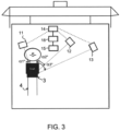
- Figs 1 , 2 and 3 are schematic top views of the cab of a vehicle equipped with a display system according to the invention, respectively in first, second and third driver seat positions.
- Fig. 1 shows a vehicle 1, more specifically a truck. Although the invention will be described with respect to a truck, the invention is not restricted to this particular vehicle, but may be used in other vehicles.
- the vehicle 1 comprises a cab 2 and three video cameras, respectively a left camera 6, a central camera 7 and a right camera 8, for example embedded in a sun visor mounted outside of the cab 2.
- the left, central and right cameras 6-8 are respectively positioned at the left, central and right part of the sun visor. These cameras are correctly positioned to capture images in surrounding areas, behind the cab 2 for the left and right cameras 6, 8 and in front of the cab 2 for the central camera 7.
- the images captured by the cameras 6-8 are transmitted in the form of electronic signals to a controller 16.
- the controller 16 is configured to convert said electronic signals in image data that can be displayed on corresponding display units, respectively a left display unit 11, a central display unit 12 and a right display unit 13, that are mounted within the cab 2 to be positioned at the left side of a driver seat 3 for the left display unit 11 and at the right side of the driver seat 3 for the central and right display units 12, 13.
- Each display unit 11-13 is pivotally connected to the cab 2 via a pivot point such that its orientation relative to the driver seat 3 is adjustable. This orientation may be defined, for instance, by the angle between an axis connecting each display unit 11-13 to the center of gravity of the driver seat 3 and a longitudinal direction D defined by the vehicle 1. This angle may also vary when the driver seat 3 is moving in the cab 2.
- the driver seat 3 may be slidably movable along rails 4 so that its position along the longitudinal direction D is adjustable. The distance between the driver seat 3 and the steering wheel 5 may thus be shortened or increased. Furthermore, the driver seat 3 may pivot around a vertical axis so that its angular position relative to the longitudinal direction D is adjustable. These adjustments are not limitative for the invention. Further adjustments of the position and/orientation of the driver seat 3 within the vehicle 1 may be possible. In particular, in further embodiments (not shown) of the vehicle 1, the driver seat 3 may be movable along a lateral direction that is perpendicular to the longitudinal direction D or along a vertical direction.
- the controller 16 and the display units 11-13 form the main components of the display system 10 according to the invention.
- the display system 10 further comprises a seat position sensor device 15 that is adapted to sense in real time the current position of the driver seat 3 and to output corresponding seat position data to the controller 16.
- the seat position sensor device 15 is adapted to determine, for instance, one or a plurality of the following features:
- the seat position sensor device 15 may be chosen among a video camera, pressure sensors, electromagnetic sensors and ultrasonic sensors.
- the display system 10 further comprises a display orientating device 14 that is adapted to control the orientation of each display unit 11-13 in the cab 2.
- the display orientating device 14 is coupled to the controller 16 and is controlled by said controller 16 based on the seat position data provided by the seat position sensor device 15.
- the display orientating device 14 may thus adjust the orientations of each display unit 11-13 relative to the driver seat 3 to permit to an occupant sitting in the driver seat 3 to see the three display units 11-13 at the same viewing angle in any positions of the driver seat 3.
- these display units 11-13 may preferably be oriented so as to provide to said occupant a field of vision that is in accordance with the Regulation UN ECE n°46.
- each display unit 11-13 The method for adjusting the orientation of each display unit 11-13 is detailed in the following paragraphs, in reference to the Figs 1 to 3 .
- Fig. 1 it is illustrated the orientation of the display units 11-13 of the display system 10 when the driver seat 3 is in its normal position of use.
- the driver seat 3 In this normal position of use, the driver seat 3 is parallel to the longitudinal direction D and is distant from the steering wheel 5 to permit to an occupant seated in the driver seat 3 to hold the steering wheel 5 in his hands with his arms slightly bent.
- the current position of the driver seat 3 is sensed by the seat position sensor device 15.
- the seat position sensor device 10 may thus determine seat position data corresponding to said current position of the driver seat 3.
- the determined seat position data are transmitted to the controller 16 that is coupled to the seat position sensor device 10.
- the controller 16 determines the orientations of the display units 11-13 based on said determined seat position data.
- the determined orientations may result from a complex calculation in which the relative positions and orientations between the display units 11-13 and the driver seat 3 are the main parameters. This complex calculation is specifically adapted to find the best orientations of the display units 11-13 that permit to an occupant seated in the driver seat 3 to see each display unit 11-13 at the same viewing angle in any positions of the driver seat 3.
- This third step is performed automatically by the controller 16.
- the determined orientations may for example be expressed by the respective angles ⁇ 1, ⁇ 2 and ⁇ 3 between an axis connecting the left, central and right display units 11-13 to the center of gravity of the driver seat 3 and the longitudinal direction D.
- the controller 16 controls the display orientating device 14 so that it adjusts the orientations of the display units 11-13 to the determined orientations.
- Fig. 2 it is illustrated the orientation of the display units 11-13 of the display system 10 when the driver seat 3 has been pivotally moved about a vertical axis from the normal position of use of Fig. 1 .
- the driver seat 3 In this second position of use, the driver seat 3 is obliquely oriented relative to the longitudinal direction D.
- the display system 10 determines the new orientations of the display units 11-13, expressed by the angles ⁇ 1', ⁇ 2' and ⁇ 3' in Fig. 2 , and the orientations of the display units 11-13 are adjusted by the display system 10 to said new orientations.
- Fig. 3 it is illustrated the orientation of the display units 11-13 of the display system 10 when the driver seat 3 has been moved along the rails 4 from the normal position of use of Fig. 1 to be closer to the steering wheel 5.
- the display system 10 determines the new orientations of the display units 11-13, expressed by the angles ⁇ 1", ⁇ 2" and ⁇ 3" in Fig. 3 , and the orientations of the display units 11-13 are adjusted by the display system 10 to said new orientations.
- the display system 10 may further comprise a memory storing reference data relative to the specific positions of use illustrated in Figs 1 to 3 , or relative to a plurality of further reference positions of the driver seat 3.
- the controller 16 is adapted to compare the seat position data received from the seat position sensor device 15 with said reference data and to determine if the current position of the driver seat 3 corresponds to a specific reference position stored in the memory. Therefore, when the current position of the driver seat 3 corresponds to a specific reference position stored in the memory, the complex calculation for the determination of the best orientations of the display units 11-13 may advantageously be avoided, these best orientations being already stored in the memory for each reference position of the driver seat 3. This results in a reduced execution time of the fourth step and, accordingly, of the method of the present invention.
- the display system 10 may comprise only two display units, or more than three display units.
Landscapes
- Engineering & Computer Science (AREA)
- Mechanical Engineering (AREA)
- Multimedia (AREA)
- Aviation & Aerospace Engineering (AREA)
- Transportation (AREA)
- Fittings On The Vehicle Exterior For Carrying Loads, And Devices For Holding Or Mounting Articles (AREA)
Claims (14)
- Véhicule (1) comprenant :- des caméras vidéo (6-8) agencées à l'extérieur du véhicule (1) et adaptées pour capturer des images autour du véhicule (1) ;- un siège conducteur (3) monté à l'intérieur du véhicule (1), la position dudit siège conducteur (3) à l'intérieur du véhicule (1) étant variable ; et- un système d'affichage (10), le système d'affichage (10) comprenant :- au moins deux unités d'affichage (11-13) montées à l'intérieur d'un véhicule (1) de manière à être positionnées de part et d'autre d'un siège conducteur (3), lesdites unités d'affichage (11-13) étant adaptées pour afficher les images capturées par les caméras vidéo (6-8), dans lequel l'orientation de chaque unité d'affichage (11-13) par rapport au siège conducteur (3) est réglable ;- un dispositif d'orientation d'affichage (14) adapté pour commander l'orientation de chaque unité d'affichage (11-13) à l'intérieur du véhicule (1) ;- un dispositif capteur de position de siège (15) adapté pour détecter en temps réel la position du siège conducteur (3) à l'intérieur du véhicule (1) et pour délivrer en sortie des données de position de siège correspondantes ; et- une unité de commande (16) couplée au dispositif d'orientation d'affichage (14) et au dispositif capteur de position de siège (15) et adaptée pour commander automatiquement le dispositif d'orientation d'affichage (14) sur la base des données de position de siège reçues du dispositif capteur de position de siège (15) de sorte que les orientations des au moins deux unités d'affichage (11-13) par rapport au siège conducteur (3) soient réglées pour permettre à un occupant assis sur le siège conducteur (3) de voir les deux unités d'affichage (11-13) sous le même angle de vue dans toutes les positions du siège conducteur (3).
- Véhicule (1) selon la revendication 1, caractérisé en ce que le dispositif capteur de position de siège (15) est adapté pour déterminer la distance entre le centre de gravité du siège conducteur (3) et un point fixe à l'intérieur du véhicule (1).
- Véhicule (1) selon la revendication 1 ou la revendication 2, caractérisé en ce que le dispositif capteur de position de siège (15) est adapté pour déterminer la distance entre le centre de gravité du siège conducteur (3) et un plan horizontal et/ou vertical à l'intérieur du véhicule (1).
- Véhicule (1) selon l'une des revendications précédentes, caractérisé en ce que le dispositif capteur de position de siège (15) est adapté pour déterminer l'orientation du siège conducteur (3) par rapport à un plan horizontal et/ou vertical à l'intérieur du véhicule (1).
- Véhicule (1) selon l'une des revendications précédentes, caractérisé en ce que le dispositif capteur de position de siège (15) est adapté pour déterminer la position du siège conducteur (3) le long de rails (4) montés à l'intérieur du véhicule (1) et le long desquels est relié en coulissement le siège conducteur (3).
- Véhicule (1) selon la revendication 5, caractérisé en ce que le dispositif capteur de position de siège (15) est adapté pour déterminer la distance entre le centre de gravité du siège conducteur (3) et un plan défini par les rails (4).
- Véhicule (1) selon la revendication 5 ou la revendication 6, caractérisé en ce que le dispositif capteur de position de siège (15) est adapté pour déterminer la position angulaire du siège conducteur (3) par rapport à un plan perpendiculaire au plan défini par les rails (4).
- Véhicule (1) selon l'une des revendications précédentes, caractérisé en ce que le dispositif capteur de position de siège (15) est choisi parmi une caméra vidéo, des capteurs de pression, des capteurs électromagnétiques et des capteurs ultrasonores.
- Véhicule (1) selon l'une des revendications précédentes, caractérisé en ce que le système (10) comprend en outre une mémoire stockant des données de référence relatives à une pluralité de positions de référence du siège conducteur (3) et en ce que l'unité de commande (16) est adaptée pour comparer les données de position de siège reçues du dispositif capteur de position de siège (15) auxdites données de référence et pour déterminer si la position actuelle du siège conducteur (3) correspond à une position de référence spécifique.
- Véhicule (1) selon l'une des revendications précédentes, caractérisé en ce que le dispositif d'orientation d'affichage (14) est adapté pour faire pivoter chaque unité d'affichage (11-13) autour d'un axe fixe à l'intérieur du véhicule (1).
- Véhicule (1) selon l'une des revendications précédentes, caractérisé en ce que les orientations des au moins deux unités d'affichage (11-13) par rapport au siège conducteur (3) sont réglées par l'unité de commande (16) pour fournir à l'occupant un champ de vision qui est conforme au règlement UN ECE n°46.
- Procédé de réglage de l'orientation d'au moins deux unités d'affichage (11-13) d'un système d'affichage (10) à l'intérieur d'un véhicule (1) selon l'une quelconque des revendications 1 à 11, le procédé comprenant les étapes de :i) détermination d'une position actuelle du siège conducteur (3) à l'intérieur du véhicule (1) ;ii) fourniture de ladite position actuelle à une unité de commande (16) ;iii) détermination des orientations des au moins deux unités d'affichage (11-13) sur la base de ladite position actuelle, les orientations déterminées permettant à un occupant assis sur le siège conducteur (3) de voir les deux unités d'affichage (11-13) sous le même angle de vue dans toutes les positions du siège conducteur (3), ladite étape iii) étant réalisée automatiquement par l'unité de commande (16) ;iv) réglage des orientations des au moins deux unités d'affichage (11-13) aux orientations déterminées.
- Procédé selon la revendication 12, caractérisé en ce que l'étape i) est réalisée par un dispositif capteur de position de siège (15) couplé à l'unité de commande (16).
- Procédé selon la revendication 12 ou 13, caractérisé en ce que l'étape iv) est réalisée par un dispositif d'orientation d'affichage (14) couplé à l'unité de commande (16).
Applications Claiming Priority (1)
| Application Number | Priority Date | Filing Date | Title |
|---|---|---|---|
| PCT/EP2019/082724 WO2021104617A1 (fr) | 2019-11-27 | 2019-11-27 | Système d'affichage pour un véhicule et procédé de réglage de l'orientation d'unités d'affichage dans un véhicule |
Publications (3)
| Publication Number | Publication Date |
|---|---|
| EP4065420A1 EP4065420A1 (fr) | 2022-10-05 |
| EP4065420C0 EP4065420C0 (fr) | 2025-01-01 |
| EP4065420B1 true EP4065420B1 (fr) | 2025-01-01 |
Family
ID=68806717
Family Applications (1)
| Application Number | Title | Priority Date | Filing Date |
|---|---|---|---|
| EP19816225.7A Active EP4065420B1 (fr) | 2019-11-27 | 2019-11-27 | Système d'affichage pour un véhicule et procédé de réglage de l'orientation d'unités d'affichage dans un véhicule |
Country Status (4)
| Country | Link |
|---|---|
| US (1) | US12043182B2 (fr) |
| EP (1) | EP4065420B1 (fr) |
| CN (1) | CN114555423A (fr) |
| WO (1) | WO2021104617A1 (fr) |
Families Citing this family (3)
| Publication number | Priority date | Publication date | Assignee | Title |
|---|---|---|---|---|
| US11040670B2 (en) * | 2018-11-26 | 2021-06-22 | Caterpillar Paving Products Inc. | Adjustable working machine operator display system |
| CN115294830B (zh) * | 2022-08-09 | 2024-08-09 | 武汉未来幻影科技有限公司 | 驾驶模拟器的视野调整方法、视野调整装置及电子设备 |
| GB202410371D0 (en) * | 2024-07-16 | 2024-08-28 | Agco Int Gmbh | Control unit for display adaption |
Citations (1)
| Publication number | Priority date | Publication date | Assignee | Title |
|---|---|---|---|---|
| US20040036769A1 (en) * | 2002-08-26 | 2004-02-26 | Takashi Sadahiro | On-vehicle display device |
Family Cites Families (8)
| Publication number | Priority date | Publication date | Assignee | Title |
|---|---|---|---|---|
| JP5831439B2 (ja) * | 2012-12-14 | 2015-12-09 | 株式会社デンソー | 車両用情報提供装置 |
| US9386335B2 (en) | 2013-11-19 | 2016-07-05 | Atieva, Inc. | Vehicle display with automatic positioning system |
| JP6384322B2 (ja) | 2014-12-26 | 2018-09-05 | トヨタ自動車株式会社 | 車両用表示装置 |
| US10101775B2 (en) * | 2016-08-22 | 2018-10-16 | Faraday&Future Inc. | Automatic display adjustment systems and methods |
| KR102279333B1 (ko) | 2017-03-07 | 2021-07-20 | 주식회사 만도 | 차량의 디스플레이 시스템 및 이의 구동 방법 |
| GB2563287B (en) * | 2017-06-09 | 2021-05-12 | Ford Global Tech Llc | A vehicle display system and method |
| DE102017113781B4 (de) | 2017-06-21 | 2023-10-05 | SMR Patents S.à.r.l. | Verfahren zum Betreiben einer Anzeigevorrichtung für einen Kraftwagen, sowie Kraftwagen |
| CN110316063B (zh) * | 2018-03-30 | 2021-08-10 | 比亚迪股份有限公司 | 车载显示终端系统、车载显示终端的显示控制方法和车辆 |
-
2019
- 2019-11-27 WO PCT/EP2019/082724 patent/WO2021104617A1/fr not_active Ceased
- 2019-11-27 EP EP19816225.7A patent/EP4065420B1/fr active Active
- 2019-11-27 CN CN201980101358.4A patent/CN114555423A/zh active Pending
- 2019-11-27 US US17/768,010 patent/US12043182B2/en active Active
Patent Citations (1)
| Publication number | Priority date | Publication date | Assignee | Title |
|---|---|---|---|---|
| US20040036769A1 (en) * | 2002-08-26 | 2004-02-26 | Takashi Sadahiro | On-vehicle display device |
Also Published As
| Publication number | Publication date |
|---|---|
| EP4065420A1 (fr) | 2022-10-05 |
| US20240101042A1 (en) | 2024-03-28 |
| EP4065420C0 (fr) | 2025-01-01 |
| CN114555423A (zh) | 2022-05-27 |
| US12043182B2 (en) | 2024-07-23 |
| WO2021104617A1 (fr) | 2021-06-03 |
Similar Documents
| Publication | Publication Date | Title |
|---|---|---|
| US10882419B2 (en) | Vehicle and method of operating the vehicle | |
| US8702250B2 (en) | System and method for adjusting vehicle mirrors automatically based on driver head position | |
| US10150386B2 (en) | Autonomous vehicle seat positioning system | |
| US10017121B2 (en) | Method for adjusting a position of a vehicle mirror | |
| US8087791B2 (en) | Methods and systems for adjusting the position of vehicle outside mirrors | |
| US7354166B2 (en) | Automatic viewing of vehicle blind spot | |
| US20180244175A1 (en) | Autonomous vehicle seat positioning system | |
| EP4304897A1 (fr) | Système de miroir de caméra de véhicule à flux vidéo réglable | |
| EP4065420B1 (fr) | Système d'affichage pour un véhicule et procédé de réglage de l'orientation d'unités d'affichage dans un véhicule | |
| CN110239441A (zh) | 一种后视镜的视野自动调整方法和装置 | |
| EP2766223A1 (fr) | Système d'affichage virtuel pour un véhicule | |
| JP2007523007A (ja) | 車両レベル調整装置を使用してトレーラを連結する方法 | |
| US20240308402A1 (en) | Vehicle seat headrest adjustment system | |
| US20190375332A1 (en) | Automatic mirror and adjustment | |
| JP2008062805A (ja) | 車輌用後視鏡装置 | |
| US20220072999A1 (en) | Method and apparatus for side mirror auto adjust for trailering in a motor vehicle | |
| JP6365600B2 (ja) | 車両用表示装置 | |
| JP2015116853A (ja) | 車両のアウトサイドミラーの視野調整装置 | |
| JPH10278649A (ja) | 自動車における調節装置 | |
| US12246742B2 (en) | Method and control device for providing feedback to a vehicle occupant | |
| CN109849795A (zh) | 一种控制后视镜翻转的方法及系统 | |
| US20240109460A1 (en) | Vehicle having ergonomically adjustable seat assembly | |
| US12611968B2 (en) | Vehicle having ergonomically adjustable seat assembly | |
| JP2001322491A (ja) | 車載用表示方法および車載用表示装置 | |
| JP4803114B2 (ja) | 車両用表示装置 |
Legal Events
| Date | Code | Title | Description |
|---|---|---|---|
| STAA | Information on the status of an ep patent application or granted ep patent |
Free format text: STATUS: UNKNOWN |
|
| STAA | Information on the status of an ep patent application or granted ep patent |
Free format text: STATUS: THE INTERNATIONAL PUBLICATION HAS BEEN MADE |
|
| PUAI | Public reference made under article 153(3) epc to a published international application that has entered the european phase |
Free format text: ORIGINAL CODE: 0009012 |
|
| STAA | Information on the status of an ep patent application or granted ep patent |
Free format text: STATUS: REQUEST FOR EXAMINATION WAS MADE |
|
| 17P | Request for examination filed |
Effective date: 20220621 |
|
| AK | Designated contracting states |
Kind code of ref document: A1 Designated state(s): AL AT BE BG CH CY CZ DE DK EE ES FI FR GB GR HR HU IE IS IT LI LT LU LV MC MK MT NL NO PL PT RO RS SE SI SK SM TR |
|
| DAV | Request for validation of the european patent (deleted) | ||
| DAX | Request for extension of the european patent (deleted) | ||
| STAA | Information on the status of an ep patent application or granted ep patent |
Free format text: STATUS: EXAMINATION IS IN PROGRESS |
|
| 17Q | First examination report despatched |
Effective date: 20240221 |
|
| GRAP | Despatch of communication of intention to grant a patent |
Free format text: ORIGINAL CODE: EPIDOSNIGR1 |
|
| STAA | Information on the status of an ep patent application or granted ep patent |
Free format text: STATUS: GRANT OF PATENT IS INTENDED |
|
| GRAS | Grant fee paid |
Free format text: ORIGINAL CODE: EPIDOSNIGR3 |
|
| INTG | Intention to grant announced |
Effective date: 20241025 |
|
| GRAA | (expected) grant |
Free format text: ORIGINAL CODE: 0009210 |
|
| STAA | Information on the status of an ep patent application or granted ep patent |
Free format text: STATUS: THE PATENT HAS BEEN GRANTED |
|
| AK | Designated contracting states |
Kind code of ref document: B1 Designated state(s): AL AT BE BG CH CY CZ DE DK EE ES FI FR GB GR HR HU IE IS IT LI LT LU LV MC MK MT NL NO PL PT RO RS SE SI SK SM TR |
|
| REG | Reference to a national code |
Ref country code: GB Ref legal event code: FG4D |
|
| REG | Reference to a national code |
Ref country code: CH Ref legal event code: EP |
|
| REG | Reference to a national code |
Ref country code: DE Ref legal event code: R096 Ref document number: 602019064337 Country of ref document: DE |
|
| REG | Reference to a national code |
Ref country code: IE Ref legal event code: FG4D |
|
| U01 | Request for unitary effect filed |
Effective date: 20250116 |
|
| U07 | Unitary effect registered |
Designated state(s): AT BE BG DE DK EE FI FR IT LT LU LV MT NL PT RO SE SI Effective date: 20250123 |
|
| PG25 | Lapsed in a contracting state [announced via postgrant information from national office to epo] |
Ref country code: PL Free format text: LAPSE BECAUSE OF FAILURE TO SUBMIT A TRANSLATION OF THE DESCRIPTION OR TO PAY THE FEE WITHIN THE PRESCRIBED TIME-LIMIT Effective date: 20250101 |
|
| PG25 | Lapsed in a contracting state [announced via postgrant information from national office to epo] |
Ref country code: ES Free format text: LAPSE BECAUSE OF FAILURE TO SUBMIT A TRANSLATION OF THE DESCRIPTION OR TO PAY THE FEE WITHIN THE PRESCRIBED TIME-LIMIT Effective date: 20250101 |
|
| PG25 | Lapsed in a contracting state [announced via postgrant information from national office to epo] |
Ref country code: IS Free format text: LAPSE BECAUSE OF FAILURE TO SUBMIT A TRANSLATION OF THE DESCRIPTION OR TO PAY THE FEE WITHIN THE PRESCRIBED TIME-LIMIT Effective date: 20250501 Ref country code: NO Free format text: LAPSE BECAUSE OF FAILURE TO SUBMIT A TRANSLATION OF THE DESCRIPTION OR TO PAY THE FEE WITHIN THE PRESCRIBED TIME-LIMIT Effective date: 20250401 |
|
| PG25 | Lapsed in a contracting state [announced via postgrant information from national office to epo] |
Ref country code: HR Free format text: LAPSE BECAUSE OF FAILURE TO SUBMIT A TRANSLATION OF THE DESCRIPTION OR TO PAY THE FEE WITHIN THE PRESCRIBED TIME-LIMIT Effective date: 20250101 |
|
| PG25 | Lapsed in a contracting state [announced via postgrant information from national office to epo] |
Ref country code: GR Free format text: LAPSE BECAUSE OF FAILURE TO SUBMIT A TRANSLATION OF THE DESCRIPTION OR TO PAY THE FEE WITHIN THE PRESCRIBED TIME-LIMIT Effective date: 20250402 |
|
| PG25 | Lapsed in a contracting state [announced via postgrant information from national office to epo] |
Ref country code: CZ Free format text: LAPSE BECAUSE OF FAILURE TO SUBMIT A TRANSLATION OF THE DESCRIPTION OR TO PAY THE FEE WITHIN THE PRESCRIBED TIME-LIMIT Effective date: 20250101 |
|
| PG25 | Lapsed in a contracting state [announced via postgrant information from national office to epo] |
Ref country code: SM Free format text: LAPSE BECAUSE OF FAILURE TO SUBMIT A TRANSLATION OF THE DESCRIPTION OR TO PAY THE FEE WITHIN THE PRESCRIBED TIME-LIMIT Effective date: 20250101 |
|
| PG25 | Lapsed in a contracting state [announced via postgrant information from national office to epo] |
Ref country code: SK Free format text: LAPSE BECAUSE OF FAILURE TO SUBMIT A TRANSLATION OF THE DESCRIPTION OR TO PAY THE FEE WITHIN THE PRESCRIBED TIME-LIMIT Effective date: 20250101 |
|
| PLBE | No opposition filed within time limit |
Free format text: ORIGINAL CODE: 0009261 |
|
| STAA | Information on the status of an ep patent application or granted ep patent |
Free format text: STATUS: NO OPPOSITION FILED WITHIN TIME LIMIT |
|
| 26N | No opposition filed |
Effective date: 20251002 |
|
| U20 | Renewal fee for the european patent with unitary effect paid |
Year of fee payment: 7 Effective date: 20251126 |