EP4067271B1 - Préhenseur et procédé de manipulation des marchandises en détail - Google Patents
Préhenseur et procédé de manipulation des marchandises en détail Download PDFInfo
- Publication number
- EP4067271B1 EP4067271B1 EP21217046.8A EP21217046A EP4067271B1 EP 4067271 B1 EP4067271 B1 EP 4067271B1 EP 21217046 A EP21217046 A EP 21217046A EP 4067271 B1 EP4067271 B1 EP 4067271B1
- Authority
- EP
- European Patent Office
- Prior art keywords
- gripper
- bar
- piece goods
- support bar
- support
- Prior art date
- Legal status (The legal status is an assumption and is not a legal conclusion. Google has not performed a legal analysis and makes no representation as to the accuracy of the status listed.)
- Active
Links
Images


Classifications
-
- B—PERFORMING OPERATIONS; TRANSPORTING
- B65—CONVEYING; PACKING; STORING; HANDLING THIN OR FILAMENTARY MATERIAL
- B65G—TRANSPORT OR STORAGE DEVICES, e.g. CONVEYORS FOR LOADING OR TIPPING, SHOP CONVEYOR SYSTEMS OR PNEUMATIC TUBE CONVEYORS
- B65G47/00—Article or material-handling devices associated with conveyors; Methods employing such devices
- B65G47/74—Feeding, transfer, or discharging devices of particular kinds or types
- B65G47/90—Devices for picking-up and depositing articles or materials
-
- B—PERFORMING OPERATIONS; TRANSPORTING
- B65—CONVEYING; PACKING; STORING; HANDLING THIN OR FILAMENTARY MATERIAL
- B65G—TRANSPORT OR STORAGE DEVICES, e.g. CONVEYORS FOR LOADING OR TIPPING, SHOP CONVEYOR SYSTEMS OR PNEUMATIC TUBE CONVEYORS
- B65G57/00—Stacking of articles
- B65G57/02—Stacking of articles by adding to the top of the stack
- B65G57/16—Stacking of articles of particular shape
- B65G57/20—Stacking of articles of particular shape three-dimensional [3D], e.g. cubiform or cylindrical
- B65G57/22—Stacking of articles of particular shape three-dimensional [3D], e.g. cubiform or cylindrical in layers each of predetermined arrangement
- B65G57/24—Stacking of articles of particular shape three-dimensional [3D], e.g. cubiform or cylindrical in layers each of predetermined arrangement the layers being transferred as a whole, e.g. on pallets
-
- B—PERFORMING OPERATIONS; TRANSPORTING
- B65—CONVEYING; PACKING; STORING; HANDLING THIN OR FILAMENTARY MATERIAL
- B65G—TRANSPORT OR STORAGE DEVICES, e.g. CONVEYORS FOR LOADING OR TIPPING, SHOP CONVEYOR SYSTEMS OR PNEUMATIC TUBE CONVEYORS
- B65G61/00—Use of pick-up or transfer devices or of manipulators for stacking or de-stacking articles not otherwise provided for
Definitions
- the present invention relates to a gripper and a method for handling piece goods.
- grippers are already known from the prior art that have several strips designed to clamp piece goods.
- these strips or clamping strips can carry out a feed movement, whereby piece goods are held between the strips with force and the gripper can then rotate the held piece goods and/or move them relative to other piece goods. After rotation and/or displacement, the strips can be opened or their relative distance from one another can be increased, whereby the piece goods that were previously held in a clamped manner are released again.
- the piece goods can, for example, be packages with several beverage containers, so that a corresponding gripper can accept such packages and then rotate or move them as required.
- packages are known in which several beverage containers are held together by means of strapping and/or a banderol.
- packages in which articles are held together by a so-called tray on which several beverage containers stand and which tray has side tabs that have been converted into an upright orientation.
- Packages have also been known for some time in which beverage containers are held together by a flat packaging cut-out that is clipped onto the respective beverage containers from above.
- Such packaging cut-outs known in practice as top clips, can be made of cardboard and/or paperboard.
- a gripper described which receives and then manipulates piece goods, can be suspended from a portal system or designed as a component of a portal system.
- a portal system below the portal system there can be a horizontal conveyor device which transports piece goods or containers in several parallel rows. Such transport in several parallel rows has the The advantage is that piece goods or containers can be transported at high throughput and manipulated using a gripper.
- Designs are also already known in which grippers for manipulating piece goods or containers are arranged on multi-axis robot arms or are carried by multi-axis robots.
- Such a gripping device is known, for example, from EP 2 388 216 A1 known.
- the gripping device disclosed in the EP patent application has two opposing gripping means that can be used to receive piece goods. If the gripping device accidentally touches a floor surface, the two opposing gripping means can detach from a carrier, which can prevent damage to the gripping device.
- the gripping device disclosed in the DE application comprises two gripping arms for gripping objects.
- One of the two gripping arms can be connected to a vehicle.
- the other gripping arm is used to open and close the gripping device via an actuator.
- the DE 36 04 985 A1 discloses a stone stack grab that has a central support piece and gripping arms. Between the gripping arms there are additional arms that are welded to pressure rails.
- the pressure rails consist of angle profiles.
- the EN 26 32 174 A1 relates to a device for gripping stone blocks pressed into gaps.
- the device consists of a gripper crossbar with actuating devices for gripper cheeks that can be moved against each other on the gripper crossbar.
- Counter cheeks that can be spread open against the gripper cheeks are arranged centrally between the two gripper cheeks.
- the counter cheeks are hinged to a common pivot axis and, when not spread open, are pivoted against each other by means of tension springs that connect them.
- the EP 3 431 422 A1 also discloses a clamping and/or gripping device for a manipulator intended for receiving piece goods.
- the clamping and/or gripping device comprises a plurality of clamping and/or gripping elements arranged in a suspended manner, which are designed to temporarily receive piece goods from different parallel rows.
- the clamping and/or gripping elements can be delivered in pairs in order to temporarily grasp piece goods from a respective row using a respective pair of clamping and/or gripping elements.
- a clamping and/or gripping device as used in the EP 3 431 422 A1 requires a complicated mechanism in order to be able to accept piece goods from several parallel rows at the same time. Due to the acceptance of piece goods by means of a respective pair of clamping and/or gripping elements as described in the EP patent application, the device also has a structure with large dimensions and high weight or mass.
- the gripper should also have a simple structure and be characterized by compact dimensions and a low mass in relation to known grippers.
- the invention relates to a gripper for grasping piece goods that are moved in several parallel rows.
- the piece goods can be formed by containers, each of which has several combined beverage containers.
- the beverage containers can be formed, for example, by beverage bottles or PET beverage bottles and/or beverage cans.
- the gripper has at least one first gripper bar and at least one second gripper bar, wherein the at least one first gripper bar and the at least one second gripper bar are designed to carry out a feed movement.
- a respective feed movement piece goods from different parallel rows can be held clamped between the at least one first gripper bar and the at least one second gripper bar.
- the at least one gripper may have a support frame.
- the at least one first gripper bar and the at least one second gripper bar may be arranged on the support frame and may be moved on the support frame or relative to the support frame as part of a respective feed movement.
- the at least one first gripper bar and the at least one second gripper bar may thus each be arranged on the support frame or on a common support frame of the gripper so as to be movable in a linear direction.
- the at least one first gripper bar and the at least one second gripper bar may be arranged on the support frame or on the common support frame in such a way that a longitudinal extension of the at least one first gripper bar and a longitudinal extension of the at least one second gripper bar run parallel to one another.
- At least one first gripper bar and/or the at least one second gripper bar each has a flexible contact area, optionally made of rubber and/or plastic, via which the at least one first gripper bar or the at least one second gripper bar can come into contact with piece goods under the influence of force.
- the gripper comprises at least one support bar, which is arranged between the at least one first gripper bar and the at least one second gripper bar.
- the at least one support bar can have two broad side surfaces, with a first broad side surface facing the at least one first gripper bar and a second broad side surface facing the at least one second gripper bar.
- the at least one support bar can also be arranged, if necessary, together with the at least one first gripper bar and the at least one second gripper bar on the support frame or on the common support frame of the gripper.
- the at least one support bar can be arranged on the support frame or on the common support frame in such a way that a longitudinal extension of the at least one support bar runs parallel to the longitudinal extension of the at least one first gripper bar and parallel to the longitudinal extension of the at least one second gripper bar.
- the at least one support bar is mounted so as to be movable relative to the at least one first gripper bar and to the at least one second gripper bar such that the at least one support bar can change its position as required for the force-loaded attachment to piece goods from different parallel rows within the scope of a respective feed movement.
- the at least one support bar is mounted so as to be movable relative to the at least one first gripper bar and to the at least one second gripper bar such that the at least one support bar can change its position as required for the force-applied attachment to piece goods from different parallel rows within the scope of a respective feed movement and can be moved in a linear direction between the at least one first gripper bar and the at least one second gripper bar.
- the additional force-loaded attachment of piece goods from different rows to at least one support bar can ensure that piece goods from several parallel rows can be held securely by the gripper.
- Such at least one support bar as the gripper according to the invention has, can ensure that even when receiving piece goods from several parallel rows, the piece goods do not accidentally come loose from the gripper after being clamped by the gripper.
- the piece goods from the different parallel rows are held in a precisely predetermined position by the force-loaded system on at least one support bar, so that it can be guaranteed with a high degree of certainty that the piece goods are in a desired orientation after manipulation via the gripper and do not slip unintentionally during manipulation.
- one support bar or several support bars are connected to the at least one first gripper bar via at least one spring in such a way that the at least one spring is compressed and tensioned if the one support bar or the several support bars change their position for the force-loaded attachment to piece goods from different parallel rows within the scope of a respective feed movement and in doing so approach the at least one first gripper bar.
- one support bar or several support bars are connected to the at least one second gripper bar via at least one spring in such a way that the at least one spring is compressed and tensioned if the one support bar or the several support bars change their position for the force-loaded application to piece goods from different parallel rows within the scope of a respective feed movement and in doing so approaches the at least one second gripper bar.
- the at least one spring can be formed by at least one spiral spring.
- the invention is not limited to such embodiments, so that the at least one spring can, for example, also be designed as a hydraulically and/or pneumatically operating spring.
- the gripper can comprise a support frame on which a first support bar and a second support bar are arranged.
- the first support bar and the second support bar can be arranged on the support frame in such a way that the longitudinal extension of the first support bar and the longitudinal extension of the second support bar run parallel to one another.
- the first support bar and the second support bar can be located between the at least one first gripper bar and the at least one second gripper bar, wherein the first support bar and the second support bar are each mounted on the support frame so as to be movable relative to the at least one first gripper bar and the at least one second gripper bar such that the first support bar and the second support bar can change their position for the respective force-loaded attachment to piece goods from different parallel rows as required within the scope of a respective feed movement.
- the gripper can comprise at least one spacer bar, which at least one spacer bar is located between the first support bar and the second support bar and is arranged in a fixed position on the support frame.
- the at least one spacer bar can be arranged in a fixed position on the support frame in such a way that a longitudinal extension of the at least one spacer bar runs parallel to the respective longitudinal extension of the first support bar and the second support bar.
- the gripper can form at least one elongated hole, via which at least one support bar is mounted so that it can move in a linear direction.
- the at least one support bar is mounted so that it can move in a linear direction via at least one elongated hole have proven themselves in practice, since such a mounting can easily limit the freedom of movement for the at least one support bar.
- the at least one support bar can be returned to an initial position when the at least one first gripper bar and the at least one second gripper bar are opened, which initial position is predetermined via an end region of the at least one elongated hole.
- the invention also relates to a portal system with at least one gripper according to at least one embodiment of the previous description.
- the portal system also comprises at least one horizontal conveyor device for moving piece goods in several parallel rows and a control and/or regulating device.
- the at least one gripper can be controlled via the control and/or regulating device in such a way that the piece goods moved in several parallel rows via the at least one horizontal conveyor device can be transferred into a relative alignment to one another by rotating and/or shifting as required, which is coordinated with a palletizable position to be formed from several piece goods.
- the at least one horizontal conveyor device can optionally comprise at least one rotating driven conveyor belt on which the piece goods moved in several parallel rows stand.
- the invention also relates to a method for handling piece goods.
- Features which have already been mentioned previously for embodiments of the portal system and for embodiments of the gripper can also be provided in the embodiments of the method described below and are not mentioned more than once.
- the method provides that at least one horizontal conveyor moves piece goods in several parallel rows and that at least one gripper pushes piece goods from the several parallel rows together via at least one first gripper bar and at least one second gripper bar until the piece goods from the several parallel rows are held clamped between the at least one first gripper bar and the at least one second gripper bar.
- the at least one gripper has at least one support bar, which is located between the at least one first gripper bar and the at least one second gripper bar.
- the at least one support bar is pushed together by its movable bearing together with the respective piece goods from the several different parallel rows until the at least one support bar comes into contact with piece goods from different parallel rows under the influence of force and the piece goods from the different parallel rows are held clamped between the at least one first gripper bar and the at least one second gripper bar under the influence of force on the at least one support bar.
- one support bar or several support bars are connected to the at least one first gripper bar via at least one spring, wherein the at least one spring is tensioned during the pushing together from a contact of the one support bar or the several support bars with piece goods of a row, whereby the one support bar or the several support bars are in contact with the piece goods of this row via the spring force of the then tensioned spring.
- one support bar or several support bars may be connected to the at least one second gripper bar via at least one spring, wherein the at least one spring is tensioned during the pushing together from a contact of the one support bar or the several support bars with piece goods in a row, whereby the one support bar or the several support bars are in contact with the piece goods in this row via the spring force of the then tensioned spring.
- the at least one spring is at least one spiral spring.
- the at least one spring can also be designed as a hydraulically and/or pneumatically operating spring.
- the piece goods held clamped between the at least one first gripper bar and the at least one second gripper bar are rotated and/or displaced relative to other piece goods arranged on the at least one horizontal conveyor and are then released, whereupon the at least one horizontal conveyor moves the released piece goods.
- the one support bar or the several support bars, which are connected to the at least one first gripper bar via the at least one spring are moved back to an initial position by means of the spring force of the at least one spring that was tensioned until then.
- the one support bar or the several support bars, which are connected to the at least one second gripper bar via the at least one spring, are moved back to an initial position by means of the spring force of the at least one spring that has been tensioned until then.
- the one support bar or the several support bars which are connected to the at least one first gripper bar via the at least one spring, are moved back to an initial position by means of a relative movement of the at least one first gripper bar relative to the one support bar or relative to the several support bars, which initial position is predetermined via at least one elongated hole, via which at least one elongated hole the one support bar or the several support bars are mounted so as to be movable in a linear direction.
- the one support bar or the several support bars which are connected to the at least one second gripper bar via the at least one spring, are moved back to an initial position by means of a relative movement of the at least one second gripper bar relative to the one support bar or relative to the several support bars, which initial position is reached via at least one elongated hole is specified, via which at least one elongated hole the one support bar or the several support bars are mounted so as to be movable in a linear direction.
- the piece goods held clamped between the at least one first gripper bar and the at least one second gripper bar are rotated and/or displaced relative to other piece goods arranged on the at least one horizontal conveyor and are then released, whereupon the at least one horizontal conveyor moves the released piece goods forward.
- the at least one spring can be pulled out beyond a rest position by the one support bar or the multiple support bars being in contact with previously clamped piece goods and the at least one first gripper bar, which is connected to the one support bar or the multiple support bars, being moved relative to the one support bar or the multiple support bars or increasing its relative distance to the one support bar or the multiple support bars.
- the at least one spring can be pulled out beyond a rest position by the one support bar or the multiple support bars being in contact with previously clamped piece goods and the at least one second gripper bar, which is connected to the one support bar or the multiple support bars, being moved relative to the one support bar or the multiple support bars.
- Such embodiments have proven to be useful if the spring force of the at least one spring is not sufficient to transfer the respective support bar to a starting position.
- the at least one gripper may have a first support bar and a second support bar, which are each located between the at least one first gripper bar and the at least one second gripper bar and are each arranged on a support frame of the at least one gripper, wherein the first support bar and the second support bar are pushed together by a respective movable bearing on the support frame together with the respective piece goods from the several different parallel rows until the first support bar and the second support bar each come into contact with piece goods from different parallel rows under force and the piece goods from the different parallel rows come into contact with the first Support bar and the second support bar are held clamped between the at least one first gripper bar and the at least one second gripper bar.
- At least one spacer bar can be provided, which is located between the first support bar and the second support bar and is mounted in a stationary manner on the support frame, wherein piece goods from different parallel rows come into contact with the at least one spacer bar under the influence of force during the respective pushing together and the piece goods from the different parallel rows are held clamped between the at least one first gripper bar and the at least one second gripper bar under the influence of force on the at least one spacer bar.
- the at least one gripper can be guided via a portal system, wherein the at least one gripper brings the piece goods from the several parallel rows, which the at least one gripper holds clamped between the at least one first gripper bar and the at least one second gripper bar under force-applied contact with the at least one support bar, into a relative orientation with respect to other piece goods by rotating and/or displacing, which relative orientation is coordinated with a palletizable layer to be formed from several piece goods.
- the at least one gripper is guided by a multi-axis robot or articulated arm robot, wherein the at least one gripper brings the piece goods from the several parallel rows, which the at least one gripper holds clamped between the at least one first gripper bar and the at least one second gripper bar under force-applied contact with the at least one support bar, into an alignment with respect to other piece goods by rotating and/or shifting, which relative alignment is coordinated with a palletizable layer to be formed from several piece goods.
- the at least one gripper manipulates the piece goods from the different parallel rows and, in particular, displaces and/or rotates them, while the piece goods from the different parallel rows are held clamped between the at least one first gripper bar and the at least one second gripper bar.
- FIGS. 1A to 3B each show an embodiment of a gripper 1 according to the invention and illustrate individual steps as they are carried out in various embodiments of the method 100 according to the invention.
- the gripper 1 is shown in the top views of the Figures 1A and 1B shown only schematically and can in practice be guided by a portal system.
- a portal system can have several grippers 1 as shown in Figures 1A to 1C which several grippers 1 move the portal system in a coordinated manner.
- the piece goods 6, which are containers 8, are on a Figures 1A and 1B not shown further horizontal conveyor device, which is thus located in the direction of the image below the piece goods 6 or below the containers 8.
- Each container 8 comprises several articles 2, which in the present case are each designed as a beverage container 4 and are held together by a strapping 5.
- articles 2 of a package 8 can be held together by adhesive bonds and/or by flat packaging cuts.
- the horizontal conveyor device moves the piece goods 6 or the containers 8 in two parallel rows 31 and 32 along the transport direction TR.
- the configuration of the gripper 1 is adapted to the clamping acceptance of piece goods 6, which are moved in exactly two parallel rows 31 and 32.
- the gripper 1 can clamp piece goods 6 or containers 8 of the first row 31 as well as additional piece goods 6 or containers 8 of the second row 32 within the scope of a work cycle and then, if necessary, move them diagonally or perpendicularly to the transport direction TR and, if necessary, rotate them about a vertical axis. By rotating and moving them diagonally or vertically in this way, the gripper 1 brings several piece goods 6 or containers 8 into a relative arrangement to one another, which is coordinated with later palletizing.
- the piece goods 6 or the containers 8 can then be moved using the horizontal conveyor.
- the piece goods 8 can maintain their contact with the horizontal conveyor at all times, so that the gripper 1 does not have to lift the piece goods 8 in order to turn the piece goods 8 or move them at an angle or perpendicular to the transport direction TR.
- Each container 8 of the first row 31 comprises exactly four beverage containers 4. Furthermore, each container 8 of the second row 32 comprises exactly six beverage containers 4, so that the containers 8 moved with the first row 31 differ from the containers 8 moved with the second row 32 with regard to their size or dimensions.
- FIG. 1A A summary of the Fig. 1A with the Fig. 1B already makes it clear that the first gripper bar 12 and the second gripper bar 14 carry out a feed movement for the respective clamped receipt of containers 8 from the first row 31 and from the second row 32, in which the first gripper bar 12 and the second gripper bar 14 approach each other or reduce their relative distance from each other.
- Such a feed movement is brought about by means of an actuator designed as a component of the gripper 1, which moves the first gripper bar 12 and the second gripper bar 14 towards each other in a linear direction in order to clamp piece goods 6 from the first row 31 and piece goods 6 from the second row 32.
- the gripper 1 is lowered in the direction from above until all the piece goods 6 of the first row 31 and the second row 32 to be received within the scope of a respective work cycle are located between the first gripper bar 12 and the second gripper bar 14.
- the gripper 1 can be moved along with the piece goods 6 while the first gripper bar 12 and the second gripper bar 14 carry out their feed movement.
- a speed of the gripper 1 can correspond to a conveying speed of the horizontal conveyor at which the horizontal conveyor moves piece goods 6 in the transport direction TR.
- the multi-axis robot can guide the gripper 1 by moving its working arm at a speed synchronized with the piece goods 6. If the gripper 1 is arranged hanging on a gantry system, the gripper 1 can be carried along via the gantry system at a speed synchronized with the piece goods 6 moved in two parallel rows 31 and 32.
- the gripper 1 comprises a support bar 20, which is arranged between the first gripper bar 12 and the second gripper bar 14.
- the support bar 20 is mounted so that it can move, that the support bar 20 can change its position if the first gripper bar 12 and the second gripper bar 14 carry out a feed movement for the clamped acceptance of piece goods 6.
- the support bar 20 can come into contact with piece goods 6 of the first row 31 as well as with piece goods 6 of the second row 32, each time with force applied.
- the support bar 20 can be moved together with the first gripper bar 12 and the second gripper bar 14 via its own actuator and is adjusted perpendicular to the transport direction TR. In the present case, however, the support bar 20 is moved passively by means of a feed movement or is pushed together with the piece goods 6 of the first row 31 and the piece goods 6 of the second row 32 via the first gripper bar 12 and the second gripper bar 14.
- the support bar 20 is connected to the first gripper bar 12 via a spring 16, which is designed as a spiral spring 16'.
- the spring 16 is not tensioned or is in a rest position. If the first gripper bar 12 and the second gripper bar 14 carry out a feed movement for the clamped acceptance of piece goods 6, the first gripper bar 12 and the second gripper bar 14 are moved towards each other with the same stroke.
- the first gripper bar 12 comes into surface contact with the piece goods 6 of the first row 31 at a certain point in time and then pushes these piece goods 6 in the direction of the opposite second gripper bar 14.
- the second gripper bar 14 comes into surface contact with the piece goods 6 of the first row 31 at a certain point in time during such a feed movement or such a stroke. time with piece goods 6 of the second row 32 in surface contact and then pushes these piece goods 6 of the second row 32 in the direction of the first gripper bar 12.
- the Figures 1A and 1B show that the piece goods 6 of the second row 32 have larger dimensions or a larger extension perpendicular to the transport direction TR. Since the first gripper bar 12 and the second gripper bar 14 are moved towards each other at the same speed during a feed movement, surface contact occurs between the piece goods 6 of the second row 32 and the gripper bar 14 before the first gripper bar 12 comes into contact with the piece goods 6 of the first row 31.
- the piece goods 6 of the second row 32 come into contact with the support bar 20, which until then was arranged approximately centrally between the first gripper bar 12 and the second gripper bar 14, during a feed movement, before the support bar 20 hits the piece goods 6 of the first row 31.
- the support bar 20 Due to the movable mounting of the support bar 20, the support bar 20 is pushed in the direction of the first gripper bar 12 during a feed movement together with the piece goods 6 of the second row 32.
- the spring 16 or the spiral spring 16' is tensioned, which presses these piece goods 6 of the second row 32 against the second gripper bar 14 with force as soon as they begin to come into contact with the piece goods 6 of the second row.
- the first gripper bar 12 also pushes the piece goods 6 of the first row 31 against the support bar 20, whereby the support bar 20 cannot be moved further in the direction of the first gripper bar 12 once it has come into contact with the piece goods 6 of the first row 31.
- Both the piece goods 6 of the first row 31 and the piece goods 6 of the second row 32 are then Fig. 1B clamped between the first gripper bar 12 and the second gripper bar 14, wherein the support bar 20 is in force-loaded contact with both the piece goods 6 of the first row 31 and the piece goods 6 of the second row 32.
- the gripper 1 described thus has a high degree of flexibility with regard to the clamping acceptance of piece goods 6 which have different dimensions and are moved in several parallel rows 31 or 32.
- the structure of the gripper 1 is also kept simple, so that such a gripper 1 can manage without complex mechanics.
- the piece goods 6 of the first row 31 and the piece goods 6 of the second row 32 are already clamped between the first gripper bar 12 and the second gripper bar 14.
- the gripper 1 can thus move the piece goods 6 at an angle or perpendicular to the transport direction TR or rotate them if necessary, if this should be necessary in order to transfer the piece goods 6 held in a clamped manner into a relative alignment with other piece goods 6 that is coordinated with later palletizing.
- the clamped connection between the gripper bars 12 or 14 and the piece goods 6 can be removed.
- first gripper bar 12 and the second gripper bar 14 are opened or the relative distance between the first gripper bar 12 and the second gripper bar 14 is increased, whereby the first gripper bar 12 and the second gripper bar 14 each lose their surface contact with the piece goods 6.
- the support bar 20 initially remains in contact with the piece goods 6 of the first row 31 and the second row 32, since the spring force of the spring 16 is only removed when the first gripper bar 12 and the second gripper bar 14 are completely opened. As the relative distance increases, the spring 16 relaxes increasingly until the spring 16 reaches a rest position corresponding to Fig. 1A Until this point in time, the support bar 20 continues to be in contact with the piece goods 6 of the first row 31 and the piece goods 6 of the second row 32.
- the first gripper bar 12 With which the support bar 20 is connected via the spring 16, is moved over a small stroke in the opposite direction to the second gripper bar 14. it is possible that the spring 16 is pulled beyond its rest position. Since the support bar 20 continues to rest on the piece goods 6 of the first row 31 during this small stroke and these piece goods 6 exert a resistance on the first support bar 20, the support bar 20 strikes an end region of the elongated hole 42 during the small stroke of the first gripper bar 12 and thus reaches a relative position intended for the support bar 20 in relation to the first gripper bar 12, in which the support bar 20 initially remains until further piece goods 6 are received again.
- the first gripper bar 12 is then moved further by a small stroke in the opposite direction to the second gripper bar 14 until a gap S is created between the piece goods 6 of the first row 31 and the piece goods 6 of the second row 32.
- the piece goods 6 of the first row 31 are thus pulled away from the piece goods 6 of the second row 32 via the support bar 20 perpendicular to the transport direction TR until a gap S is created between the piece goods 6 of the first row 31 and the piece goods 6 of the second row 32.
- the gripper 1 can be raised vertically via the portal system or the multi-axis robot and moved in the direction of further piece goods 6 for clamping acceptance.
- the piece goods 6 that have already been clamped and manipulated via the gripper 1 are fed via the horizontal conveyor to a packaging station (not shown), which forms a palletizable layer from the manipulated piece goods 6.
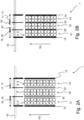
- FIG. 2A and 2B show a further embodiment of a gripper 1 according to the invention and illustrate individual steps as they occur in various embodiments of the method 100 according to the invention (cf. Fig.4 ) may be provided.
- the gripper 1 according to the embodiment according to Figures 2A and 2B comprises a first gripper bar 12 and a second gripper bar 14, which can carry out a feed movement for the clamping acceptance of piece goods 6.
- the Figures 2A and 2B A horizontal conveyor system (not shown) transports piece goods 6 in three rows 31, 32 and 33 along the transport direction TR.
- the gripper 1 according to the embodiment according to Figures 2A and 2B is able to transport piece goods 6 from three different different parallel rows 31, 32 and 33 by the gripper 1 executing a respective feed movement via the first gripper bar 12 and the second gripper bar 14.
- first gripper bar 12 and the second gripper bar 14 in the embodiment of a gripper 1 according to Figures 2A and 2B exactly two support strips 20 and 22 are arranged.
- the support strip 20 is connected to the first gripper strip 12 via a spring 16.
- the support strip 22 is connected to the second gripper strip 14 via a spring 17.
- the first support strip 20 and the second support strip 22 are mounted in a respective slot 42 or 43 so that they can move in a linear direction against the restoring force of a respective spring 16 or 17.
- the gripper 1 from the embodiment according to Figures 2A and 2B initially lowered from above in the direction of the piece goods 6.
- Piece goods 6 of the first row 31 are then located between the first gripper bar 12 and the support bar 20.
- Piece goods 6 of the second row 32 are then located between the support bars 20 and 22.
- Piece goods 6 of the third row 33 are located after lowering the gripper 1 or accordingly Fig. 2A between the support bar 22 and the second gripper bar 14.
- the first gripper bar 12 and the second gripper bar 14 are moved towards each other with an identical stroke, whereby the first gripper bar 12 comes into surface contact with the piece goods 6 of the first row 31 and the second gripper bar 14 comes into surface contact with the piece goods 6 of the third row 33. At the same time, the first gripper bar 12 pushes the support bar 20, with which the first gripper bar 12 is connected via the spring 16, until it stops against the piece goods 6 of the second row 32.
- the second gripper bar 14 which is connected to the support bar 22 via the spring 17, pushes the support bar 22 until it stops against the piece goods 6 of the second row 32.
- the support bar 20 and the support bar 22 reach thus at least approximately at the same time as general cargo 6 of the second row 32 in the system.
- the feed movement of the first gripper bar 12 and the second gripper bar 14 or the respective stroke of the first gripper bar 12 and the second gripper bar 14 takes place until the piece goods 6 of the three rows 31, 32 and 33 are held clamped between the first gripper bar 12 and the second gripper bar 14 and the support bars 20 and 22 are in contact with the piece goods 6 of the second row 32 under force.
- the support strips 20 and 22 are thus pushed together with the piece goods 6 of the three parallel rows 31, 32 and 33 via the first gripper strip 12 and the second gripper strip 14 as part of a respective delivery movement.
- the support strips 20 and 22 are moved together with the gripper strips 12 and 14 by their coupling to the gripper strips 12 and 14, provided that the gripper strips 12 and 14 carry out a respective delivery movement.
- the Fig. 2B also shows that the springs 16 and 17 are each tensioned by the feed movement.
- the springs 16 and 17 thus press the support bars 20 and 22 against the piece goods 6 of the second row 32 when the first gripper bar 12 and the second gripper bar 14 have carried out their respective feed movements.
- the piece goods 6 of the three rows 31, 32 and 33 held by the gripper 1 can be manipulated by the gripper 1 and can be displaced and/or rotated obliquely or perpendicularly to the transport direction TR in order to transfer the piece goods 6 held in a clamped manner into a relative orientation with respect to other piece goods 6 that have already been manipulated, which is coordinated with later palletizing.
- the gripper 1 can release the manipulated piece goods 6 again.
- the gripper bars 12 and 14 are opened for this purpose, with the first gripper bar 12 and the second gripper bar 14 increasing their relative distance from one another.
- the springs 16 and 17 relax, whereby the force-loaded contact of the support bars 20 and 22 on the piece goods 6 of the second row 32 decreases.
- the gripper 1 can be raised and moved in the direction of further items 6 to be clamped, after which the gripper 1 can be lowered and adjusted to an orientation Fig. 2A is brought.
- the gripper 1 may be moved as described above.
- Figures 1A to 1C the relative distance between the gripper bars 12 and 14 is further increased until the support bars 20 and 22 push the piece goods 6 of the first row 31 and the third row 33 perpendicular to the transport direction TR until a gap S (cf. Fig. 1C ) forms.
- the gripper 1 according to the embodiment according to Figures 2A and 2B is able to clamp and manipulate piece goods 6 from three parallel rows 31, 32 and 33.
- the gripper 1 has a simple structure for this purpose, so that no complex mechanics are required.
- the gripper 1 is also very compact and has a low mass compared to other grippers already known from the state of the art due to its simple and compact structure.
- FIG. 3A and 3B show a further embodiment of a gripper 1 according to the invention.
- a horizontal conveyor system (not shown) transports piece goods 6 in four parallel rows 31, 32, 33 and 34 along the transport direction TR.
- the embodiment of a gripper 1 comprises a first gripper bar 12 and a second gripper bar 14, which can carry out a feed movement for clamping receipt of piece goods 6 from the four parallel rows 31, 32, 33 and 34.
- Two support bars 20 and 22 are positioned between the first gripper bar 12 and the second gripper bar 14, which are mounted so as to be movable in a linear direction via a respective elongated hole 42 or 43.
- the support bar 20 is also connected to the first gripper bar 12 via a spring 16, while the support bar 22 is connected to the second gripper bar 14 via the spring 17.
- a spacer bar 15 between the support bars 20 and 22.
- a longitudinal extension of the spacer bar 15 is oriented parallel to the respective longitudinal extension of the support bars 20 and 22.
- the spacer bar 15 is firmly or stationary connected to the support frame 18 and thus cannot be moved relative to the support frame 18.
- the spacer bar 15 is positioned approximately centrally between the support bars 20 and 22 and approximately centrally between the first gripper bar 12 and the second gripper bar 14.
- the piece goods 6 of the first row 31 are pushed in the direction of the spacer bar 15 via the first gripper bar 12 as part of a respective feed movement.
- the support bar 20, which is connected to the first gripper bar 12 via the spring 16 pushes the piece goods 6 of the second row 32 in the direction of the spacer bar 15 until the piece goods 6 of the second row 32 strike the spacer bar 15.
- the piece goods 6 of the fourth row 34 are pushed in the direction of the spacer bar 15 via the second gripper bar 14 as part of a respective feed movement.
- the support bar 22, which is connected to the second gripper bar 14, pushes the piece goods 6 of the third row 33 in the direction of the spacer bar 15 until the piece goods 6 of the third row 33 strike the spacer bar 15.
- the Fig. 3B also shows that the springs 16 and 17, via which the support bars 20 and 22 are connected to the gripper bars 12 and 14, are tensioned during a feed movement. If the piece goods 6 of the four parallel rows are held clamped between the first gripper bar 12 and the second gripper bar 14, the springs 16 and 17 are tensioned and press the piece goods 6 of the second row 32 and the piece goods 6 of the third row 33 are subjected to force against the spacer bar 15 fixedly arranged on the support frame 18.
- the piece goods 6 held clamped between the first gripper bar 12 and 14 can then also be moved via the embodiment of a gripper 1 to Figures 3A and 3B manipulated and displaced obliquely or perpendicularly to the transport direction TR and, if necessary, rotated relative to other already manipulated piece goods 6, if this should be necessary for later palletizing.
- the relative distance between the first gripper bar 12 and the second gripper bar 14 is increased, for which purpose the first gripper bar 12 and the second gripper bar 14 each carry out a return stroke movement in the opposite direction of the spacer bar 15. This relaxes the springs 16 and 17, so that the force-loaded contact of the support bars 20 and 22 on the piece goods 6 of the second row 32 and the third row 33 can be removed.
- the support strips 20 and 22 are each mounted so as to be movable in the longitudinal direction in the respective elongated hole 42 or 43, the support strips 20 and 22 initially remain in contact with the piece goods 6 of the second row 32 and the third row 33, whereas the first clamping strip 12 and the second clamping strip 14 lose their previously formed surface contact with the piece goods 6 of the first row 31 and the piece goods 6 of the fourth row 34 when their relative distance from one another increases.
- the distance between the first gripper bar 12 and the second gripper bar 14 is increased until the springs 16 and 17 are in a rest position in which they are no longer tensioned.
- the gripper 1 can then be raised in a vertical direction, whereby the gripper 1 leaves the manipulated piece goods 6.
- first gripper bar 12 and the second gripper bar 14 it is also possible for the first gripper bar 12 and the second gripper bar 14 to increase their relative distance until the support bars 20 and 22 push the piece goods 6 of the first row 31 away from the piece goods 6 of the second row and the piece goods of the fourth row 34 away from the piece goods 6 of the third row perpendicular to the transport direction TR.
- This allows a gap to be created between the piece goods 6 of the first row 31 and the piece goods 6 of the second row 32 and between the piece goods 6 of the third row 33 and the piece goods 6 of the fourth row 34, as shown in Fig. 1C has already been shown.
- the elongated holes 42 and 43 each form a stop or an end position, which limits the respective relative movement of the support strips 20 and 22 with respect to the respective gripper strip 12 or 14.
- the Fig.4 shows in the flowchart step how in an embodiment of a method 100 according to the invention can be provided.
- piece goods 6 are moved next to one another in several parallel rows on a horizontal conveyor.
- the piece goods 6 are containers 8, each of which comprises several articles 2 designed as beverage containers 4.
- a gripper 1 carries out a feed movement in which a first gripper bar 12 and a second gripper bar 14 move towards one another and in the process push piece goods 6 of the several parallel rows together.
- the third step 130 is carried out, in which the gripper 1 manipulates the piece goods 6 held clamped between the first gripper bar 12 and the second gripper bar 14 by the gripper 1 displacing the clamped piece goods 6 obliquely or perpendicularly to a transport direction TR of the horizontal conveyor and/or rotating them if necessary in order to bring the clamped piece goods 6 into an orientation which is coordinated with later palletizing.
- step 140 which follows step 130, the clamped and manipulated piece goods 6 are released by the gripper 1 moving the first Gripper bar 12 and the second gripper bar 14 move apart and move upwards away from the piece goods 6.
Landscapes
- Engineering & Computer Science (AREA)
- Mechanical Engineering (AREA)
- Specific Conveyance Elements (AREA)
Claims (13)
- Préhenseur (1) destiné à saisir des produits de détail (6) qui sont déplacées en plusieurs rangées parallèles (31, 32, 33, 34), ledit préhenseur (1) présentantau moins une première barre de préhenseur (12) et au moins une deuxième barre de préhenseur (14), dans lequel ladite au moins une première barre de préhenseur (12) et ladite au moins une deuxième barre de préhenseur (14) sont conçues pour effectuer un mouvement d'avance, ledit mouvement d'avance respectif permet de maintenir par serrage des produits de détail (6) provenant de différentes rangées parallèles (31, 32, 33, 34), entre ladite au moins une première barre de préhenseur (12) et ladite au moins une deuxième barre de préhenseur (14), ledit préhenseur (1) étant caractérisé parau moins une barre de support (20, 22) qui est disposée entre ladite au moins une première barre de préhenseur (12) et ladite au moins une deuxième barre de préhenseur (14), dans lequel ladite au moins une barre de support (20, 22) est montée de manière déplaçable par rapport à ladite au moins une première barre de préhenseur (12) et à ladite au moins une deuxième barre de préhenseur (14) de telle sorte que, dans le cadre d'un mouvement d'avance respectif, ladite au moins une barre de support (20, 22) peut changer de position, en cas de besoin, pour un appui appliqué par force sur des produits de détail (6) provenant de différentes rangées parallèles (31, 32, 33, 34) et peut être déplacée à cette fin dans la direction linéaire entre ladite au moins une première barre de préhenseur et ladite au moins une deuxième barre de préhenseur.
- Préhenseur selon la revendication 1, dans lequel- une barre de support (20) ou plusieurs barres de support (20) sont reliées à ladite au moins une première barre de préhenseur (12) par l'intermédiaire d'au moins un ressort (16) de telle sorte que ledit au moins un ressort (16) est comprimé et tendu, dans la mesure où ladite une barre de support (20) ou lesdites plusieurs barres de support (20) change(nt) de position pour un appui appliqué par force sur des produits de détail (6) provenant de différentes rangées parallèles (31, 32, 33, 34), dans le cadre d'un mouvement d'avance respectif, et se rapproche(nt) ainsi de ladite au moins une première barre de préhenseur (12), et/ou dans lequel préhenseur- une barre de support (22) ou plusieurs barres de support (22) sont reliées à ladite au moins une deuxième barre de préhenseur (14) par l'intermédiaire d'au moins un ressort (17) de telle sorte que ledit au moins un ressort (17) est comprimé et tendu, dans la mesure où ladite une barre de support (22) ou lesdites plusieurs barres de support (22) change(nt) de position pour un appui appliqué par force sur des produits de détail (6) provenant de différentes rangées parallèles (31, 32, 33, 34), dans le cadre d'un mouvement d'avance respectif, et se rapproche(nt) ainsi de ladite au moins une deuxième barre de préhenseur (14).
- Préhenseur selon la revendication 2, dans lequel ledit au moins un ressort (16, 17) est formé par au moins un ressort spiral (16', 17').
- Préhenseur selon l'une quelconque des revendications 1 à 3, comprenant un cadre porteur (18) sur lequel- sont disposées une première barre de support (20) et une deuxième barre de support (22) qui se trouvent chacune entre ladite au moins une première barre de préhenseur (12) et ladite au moins une deuxième barre de préhenseur (14), dans lequel la première barre de support (20) et la deuxième barre de support (22) sont montées sur le cadre porteur (18) de manière à pouvoir se déplacer par rapport à ladite au moins une première barre de préhenseur (12) et à ladite au moins une deuxième barre de préhenseur (14) de telle sorte que, dans le cadre d'un mouvement d'avance respectif, la première barre de support (20) et la deuxième barre de support (22) peuvent changer de position, respectivement en cas de besoin, pour un appui respectif appliqué par force sur des produits de détail (6) provenant de différentes rangées parallèles (31, 32, 33, 34), et lequel préhenseur- comprend au moins une barre d'écartement (15), laquelle au moins une barre d'écartement (15) se trouve entre la première barre de support (20) et la deuxième barre de support (22) et est disposée à poste fixe sur le cadre porteur (18).
- Préhenseur selon l'une quelconque des revendications 1 à 4, lequel préhenseur forme au moins un trou oblong (42, 43), c'est par l'intermédiaire duquel au moins un trou oblong (42, 43) que ladite au moins une barre de support (20, 22) est montée de manière à pouvoir se déplacer dans la direction linéaire.
- Système de portique comprenant- au moins un préhenseur (1) selon l'une quelconque des revendications 1 à 5,- au moins un dispositif de transport horizontal destiné à déplacer des produits de détail (6) en plusieurs rangées parallèles (31, 32, 33, 34) ainsi qu'- un dispositif de commande et/ou de régulation, dans lequelledit au moins un préhenseur (1) peut être commandé par le biais dudit dispositif de commande et/ou de régulation de telle sorte que les produits de détail (6) déplacées par l'intermédiaire dudit au moins un dispositif de transport horizontal en plusieurs rangées parallèles (31, 32, 33, 34) peuvent être amenés dans une orientation relative les uns par rapport aux autres en les tournant et/ou décalant en cas de besoin, qui est coordonnée avec une couche palettisable à former à partir de plusieurs produits de détail (6).
- Procédé (100) de manipulation de produits de détail (6), dans lequel procédé (100)- au moins un dispositif de transport horizontal déplace des produits de détail (6) en plusieurs rangées parallèles (31, 32, 33, 34) et- au moins un préhenseur (1) rapproche des produits de détail (6) provenant desdites plusieurs rangées parallèles (31, 32, 33, 34) par l'intermédiaire d'au moins une première barre de préhenseur (12) et au moins une deuxième barre de préhenseur (14) jusqu'à ce que les produits de détail (6) provenant des plusieurs rangées parallèles (31, 32, 33, 34) soient maintenues par serrage entre ladite au moins une première barre de préhenseur (12) et ladite au moins une deuxième barre de préhenseur (14), le procédé (100) étant caractérisé par le fait que- ledit au moins un préhenseur (1) présente au moins une barre de support (20, 22) qui est située entre ladite au moins une première barre de préhenseur (12) et ladite au moins une deuxième barre de préhenseur (14), laquelle au moins une barre de support (20, 22) est poussée, grâce à son montage déplaçable, conjointement avec les produits de détail (6) respectifs provenant des plusieurs rangées parallèles (31, 32, 33, 34) jusqu'à ce que ladite au moins une barre de support (20, 22) vienne ainsi en appui, respectivement par application de force, sur des produits de détail (6) provenant de différentes rangées parallèles (31, 32, 33, 34), et que les produits de détail (6) provenant des différentes rangées parallèles (31, 32, 33, 34) soient maintenus par serrage entre ladite au moins une première barre de préhenseur (12) et ladite au moins une deuxième barre de préhenseur (14) en étant en appui appliqué par force sur ladite au moins une barre de support (20, 22).
- Procédé selon la revendication 7, dans lequel- une barre de support (20) ou plusieurs barres de support (20) sont reliées à ladite au moins une première barre de préhenseur (12) par l'intermédiaire d'au moins un ressort (16), dans lequel ledit au moins un ressort (16) est tendu pendant le rapprochement à partir d'un moment où ladite une barre de support (20) ou lesdites plusieurs barres de support (20) entre(nt) en contact avec des produits de détail (6) d'une rangée (31, 32, 33, 34), ce par quoi ladite une barre de support (20) ou lesdites plusieurs barres de support (20) est/sont en appui par application de force, au moyen de la force du ressort (16) qui est alors tendu, sur les produits de détail (6) de cette rangée (31, 32, 33, 34), et/ou dans lequel procédé- une barre de support (22) ou plusieurs barres de support (22) sont reliées à ladite au moins une deuxième barre de préhenseur (14) par l'intermédiaire d'au moins un ressort (17), dans lequel ledit au moins un ressort (17) est tendu pendant le rapprochement à partir d'un moment où ladite une barre de support (22) ou lesdites plusieurs barres de support (22) entre(nt) en contact avec des produits de détail (6) d'une rangée (31, 32, 33, 34), ce par quoi ladite une barre de support (22) ou lesdites plusieurs barres de support (22) est/sont en appui par application de force, au moyen de la force du ressort (17) qui est alors tendu, sur les produits de détail (6) de cette rangée (31, 32, 33, 34).
- Procédé selon la revendication 8, dans lequel ledit au moins un ressort (16, 17) est au moins un ressort spiral (16', 17').
- Procédé selon la revendication 8 ou la revendication 9, dans lequel les produits de détail (6) maintenus par serrage entre ladite au moins une première barre de préhenseur (12) et ladite au moins une deuxième barre de préhenseur (14) sont tournées et/ou décalés par rapport à d'autres produits de détail (6) disposés sur ledit au moins un dispositif de transport horizontal et sont ensuite libérés, ce après quoi ledit au moins un dispositif de transport horizontal déplace les produits de détail (6) libérés, et dans lequel- au cours d'une libération de produits de détail (6), ladite une barre de support (20) ou lesdites plusieurs barres de support (20) qui est/sont reliée(s) à ladite au moins une première barre de préhenseur (12) par l'intermédiaire dudit au moins un ressort (16), est/sont ramenée(s) à une position de départ au moyen de la force dudit au moins un ressort (16) qui a été tendu jusqu'alors, et/ou dans lequel procédé- au cours d'une libération de produits de détail (6), ladite une barre de support (22) ou lesdites plusieurs barres de support (22) qui est/sont reliée(s) à ladite au moins une deuxième barre de préhenseur (14) par l'intermédiaire dudit au moins un ressort (17), est/sont ramenée(s) à une position de départ au moyen de la force dudit au moins un ressort (17) qui a été tendu jusqu'alors.
- Procédé selon l'une quelconque des revendications 7 à 10, dans lequelledit au moins un préhenseur (1) présente une première barre de support (20) et une deuxième barre de support (22) qui se trouvent chacune entre ladite au moins une première barre de préhenseur (12) et ladite au moins une deuxième barre de préhenseur (14) et sont disposées chacune sur un cadre porteur (18) dudit au moins un préhenseur (1), dans lequel, grâce à un montage mobile respectif sur ledit cadre porteur (18), la première barre de support (20) et la deuxième barre de support (22) sont poussées conjointement avec les produits de détail (6) respectifs provenant desdites plusieurs différentes rangées parallèles (31, 32, 33, 34) jusqu'à ce que la première barre de support (20) et la deuxième barre de support (22) viennent ainsi en appui, respectivement par application de force, sur des produits de détail (6) provenant de différentes rangées parallèles (31, 32, 33, 34), et que les produits de détail (6) provenant des différentes rangées parallèles (31, 32, 33, 34) soient maintenus par serrage entre ladite au moins une première barre de préhenseur (12) et ladite au moins une deuxième barre de préhenseur (14) en étant en appui appliqué par force sur la première barre de support (20) et la deuxième barre de support (22), et dans lequel procédéau moins une barre d'écartement (15) est prévue qui est située entre la première barre de support (20) et la deuxième barre de support (22) et est montée à poste fixe sur le cadre porteur (18), dans lequel des produits de détail (6) provenant de différentes rangées parallèles (31, 32, 33, 34) viennent en appui, par application de force, pendant le rapprochement respectif, sur ladite au moins une barre d'écartement (15), et les produits de détail (6) provenant des différentes rangées parallèles (31, 32, 33, 34) sont maintenus par serrage entre ladite au moins une première barre de préhenseur (12) et ladite au moins une deuxième barre de préhenseur (14), en étant en appui appliqué par force sur ladite au moins une barre d'écartement (15).
- Procédé selon l'une quelconque des revendications 7 à 11, dans lequel ledit au moins un préhenseur (1) est guidé par un système de portique, dans lequel ledit au moins un préhenseur (1) amène les produits de détail (6) provenant des plusieurs rangées parallèles (31, 32, 33, 34) que ledit au moins un préhenseur (1) maintient par serrage entre ladite au moins une première barre de préhenseur (12) et ladite au moins une deuxième barre de préhenseur (14), pendant qu'ils sont en appui appliqué par force sur ladite au moins une barre de support (20, 22), dans une orientation relative par rapport à d'autres produits de détail (6), en les tournant et/ou décalant, laquelle orientation relative est coordonnée avec une couche palettisable à former à partir de plusieurs produits de détail (6).
- Procédé selon l'une quelconque des revendications 7 à 12, dans lequel ledit au moins un préhenseur manipule les produits de détail (6) provenant des différentes rangées parallèles (31, 32, 33, 34) et, en particulier, les décale et/ou les tourne à cette fin, tandis que les produits de détail (6) provenant des différentes rangées parallèles (31, 32, 33, 34) sont maintenues par serrage entre ladite au moins une première barre de préhenseur (12) et ladite au moins une deuxième barre de préhenseur (14), et dans lequel procédé les produits de détail (6) qui ont été maintenus par serrage jusqu'alors sont ensuite libérés, à cet effet ladite au moins une première barre de préhenseur (12) et ladite au moins une deuxième barre de préhenseur (14) sont écartées l'une de l'autre, et dans lequel ladite au moins une barre de support (20, 22) écarte des produits de détail (6) déjà manipulés de sorte que, ainsi, un espace (S) est formé entre des produits de détail (6) déjà manipulés.
Applications Claiming Priority (1)
| Application Number | Priority Date | Filing Date | Title |
|---|---|---|---|
| DE102021108435.0A DE102021108435A1 (de) | 2021-04-01 | 2021-04-01 | Greifer und Verfahren zum Umgang mit Stückgütern |
Publications (3)
| Publication Number | Publication Date |
|---|---|
| EP4067271A1 EP4067271A1 (fr) | 2022-10-05 |
| EP4067271C0 EP4067271C0 (fr) | 2024-06-12 |
| EP4067271B1 true EP4067271B1 (fr) | 2024-06-12 |
Family
ID=83104219
Family Applications (1)
| Application Number | Title | Priority Date | Filing Date |
|---|---|---|---|
| EP21217046.8A Active EP4067271B1 (fr) | 2021-04-01 | 2021-12-22 | Préhenseur et procédé de manipulation des marchandises en détail |
Country Status (3)
| Country | Link |
|---|---|
| EP (1) | EP4067271B1 (fr) |
| CN (1) | CN218230865U (fr) |
| DE (1) | DE102021108435A1 (fr) |
Families Citing this family (7)
| Publication number | Priority date | Publication date | Assignee | Title |
|---|---|---|---|---|
| DE102021131120A1 (de) * | 2021-11-26 | 2023-06-01 | Krones Aktiengesellschaft | Greifvorrichtung und Verfahren zur Handhabung von Stückgütern |
| DE102022132194A1 (de) * | 2022-12-05 | 2024-06-06 | Krones Aktiengesellschaft | Greiferkopf und Verfahren zum Manipulieren von Stückgütern sowie Dreh- und Verteilsystem mit solchem Greiferkopf |
| DE102022132192A1 (de) | 2022-12-05 | 2024-06-06 | Krones Aktiengesellschaft | Greiferkopf und Verfahren zum Manipulieren von Stückgütern sowie Dreh- und Verteilsystem mit solchem Greiferkopf |
| WO2024121039A1 (fr) | 2022-12-05 | 2024-06-13 | Krones Aktiengesellschaft | Tête de préhension, procédé de manipulation de marchandises à la pièce et système de rotation et de distribution comprenant une telle tête de préhension |
| DE102022132191A1 (de) | 2022-12-05 | 2024-06-06 | Krones Aktiengesellschaft | Greiferkopf und Verfahren zum Erfassen und Manipulieren von Stückgütern |
| DE102022132193A1 (de) | 2022-12-05 | 2024-06-06 | Krones Aktiengesellschaft | Greiferkopf und Verfahren zum Erfassen und Manipulieren von Stückgütern |
| DE102023131679A1 (de) * | 2023-11-14 | 2025-05-15 | Krones Aktiengesellschaft | Greiferkopf und Verfahren zum Erfassen und Manipulieren von Stückgütern |
Family Cites Families (20)
| Publication number | Priority date | Publication date | Assignee | Title |
|---|---|---|---|---|
| DE1120967B (de) * | 1957-11-09 | 1961-12-28 | Atlas Werke Ag | Vorrichtung zum Stapeln noch zu haertender, von einer Formmaschine kommender Formlinge von Steinen |
| GB870866A (en) * | 1958-04-09 | 1961-06-21 | Gordon Henry Bennett | Improvements in or relating to gripping means for lifting loading or stacking equipment |
| DE2632174C2 (de) * | 1976-07-16 | 1983-10-13 | Dorstener Maschinenfabrik Ag, 4270 Dorsten | Vorrichtung zum Greifen von im Zuge der Herstellung von Steinen, insbesondere Kalksandsteinen, auf Lücke gepreßten Steinformlingen |
| DE3409108A1 (de) * | 1984-03-13 | 1985-09-26 | Dorstener Maschinenfabrik Ag, 4270 Dorsten | Vorrichtung zum greifen von im zuge des herstellens von steinen, insbesondere kalksandsteinen, auf dem pressentisch einer formpresse fertiggepressten steinformlingen |
| DE3604985A1 (de) * | 1986-02-17 | 1987-08-20 | Kinshofer Greiftechnik | Steinstapelgreifer |
| DE10204513A1 (de) | 2002-02-05 | 2003-08-21 | Probst Gmbh | Greifvorrichtung zum Greifen von Gegenständen, insbesondere von Baustoffpaketen |
| DE10219129B4 (de) * | 2002-04-29 | 2004-05-27 | Schaefer Förderanlagen- und Maschinenbau GmbH | Vorrichtung zum Drehen und Verteilen oder Zusammenführen von Packs |
| WO2006098556A1 (fr) * | 2005-03-18 | 2006-09-21 | Lg Household & Health Care Ltd. | Main de robot de cargaison de marchandises |
| DE102009003845A1 (de) | 2009-04-29 | 2010-11-04 | Krones Ag | Vorrichtung und Verfahren zum definierten Zusammenführen von Gebinden und/oder Gebindegruppen |
| DE202010003363U1 (de) | 2010-03-09 | 2010-06-02 | Langenstein & Schemann Gmbh | Vorrichtung zum Stapeln von Stapelkörpern, insbesondere Kalksandsteinen, sowie Anordnung von Stapelkörpern, insbesondere Kalksandsteinen, zu einem Stapel |
| DE102010020847A1 (de) | 2010-05-18 | 2011-11-24 | Krones Ag | Greifvorrichtung |
| ITVI20120084A1 (it) * | 2012-04-16 | 2013-10-17 | Marcheluzzo Impianti S R L | Procedimento e struttura per il prelievo e la calibratura di laterizi in argilla umida |
| CN103042534B (zh) * | 2013-01-18 | 2015-07-22 | 江苏中科友特机器人科技有限公司 | 一种多功能机械手爪 |
| DE102013207091A1 (de) | 2013-04-19 | 2014-10-23 | Krones Aktiengesellschaft | Gruppierverfahren und -vorrichtung |
| DE102013113754A1 (de) * | 2013-12-10 | 2015-06-11 | Krones Aktiengesellschaft | Verfahren zur Bildung von Gebinden und zu deren Palettierung sowie Förder- und Handhabungsvorrichtung für Artikel und Gebinde |
| DE102016202182A1 (de) | 2016-02-12 | 2017-08-17 | Krones Aktiengesellschaft | Vorrichtung und Verfahren zum Manipulieren von Stückgütern eines Stückgutstromes |
| DE102017002752A1 (de) | 2017-03-22 | 2018-09-27 | Krones Ag | Verfahren und Vorrichtung zum Umgang mit bewegten Stückgütern zum Ausbilden einer palettierfähigen Lage |
| DE102017116154A1 (de) | 2017-07-18 | 2019-01-24 | Krones Aktiengesellschaft | Greifeinrichtung für einen Manipulator und Verfahren zum Ausrüsten einer für einen Manipulator vorgesehenen Greifeinrichtung |
| DE102017215122A1 (de) | 2017-08-30 | 2019-02-28 | Krones Aktiengesellschaft | Vorrichtung und Verfahren zum Umgang mit in mindestens einer Reihe hintereinander bewegten Stückgütern |
| DE102017123558A1 (de) | 2017-10-10 | 2019-04-11 | Krones Aktiengesellschaft | Vorrichtung und Verfahren zum Umgang mit in mindestens zwei parallelen Reihen bewegten Stückgütern |
-
2021
- 2021-04-01 DE DE102021108435.0A patent/DE102021108435A1/de active Pending
- 2021-12-22 EP EP21217046.8A patent/EP4067271B1/fr active Active
-
2022
- 2022-02-08 CN CN202220258117.XU patent/CN218230865U/zh active Active
Also Published As
| Publication number | Publication date |
|---|---|
| DE102021108435A1 (de) | 2022-10-06 |
| EP4067271C0 (fr) | 2024-06-12 |
| EP4067271A1 (fr) | 2022-10-05 |
| CN218230865U (zh) | 2023-01-06 |
Similar Documents
| Publication | Publication Date | Title |
|---|---|---|
| EP4067271B1 (fr) | Préhenseur et procédé de manipulation des marchandises en détail | |
| EP2072430B1 (fr) | Dispositif de saisie de paquet pour un dispositif de palettisation et procédé de palettisation de paquets | |
| EP3260399B1 (fr) | Dispositif de préhension destiné à saisir plusieurs marchandises, système de maniement de plusieurs marchandises et procédé de manipulation de plusieurs marchandises | |
| EP1452469B1 (fr) | Palettiseur | |
| DE102013204095A1 (de) | Verfahren und Vorrichtung zum Positionieren, Ausrichten und/oder Gruppieren von Artikeln, Stückgütern oder Gebinden | |
| EP3205609B1 (fr) | Système de manutention et de palettisation de récipients de boissons et procédé de manipulation de marchandises dans un flux de marchandises de détail | |
| EP3072837A1 (fr) | Procédé et dispositif destinés à la manipulation d'articles, marchandises au détail ou de gerbes | |
| EP3652092B1 (fr) | Procédé et dispositif de manipulation de marchandises de détail, d'articles et/ou d'emballages | |
| EP3450359B1 (fr) | Dispositif et procédé de manipulation d'au moins une rangée de marchandises en mouvement les unes derrière les autres | |
| EP3431422A1 (fr) | Dispositif de préhension pour un manipulateur et procédé d'équipement d'un dispositif de préhension pour un manipulateur | |
| WO2017220215A1 (fr) | Procédé et dispositif de manutention de charges isolées déplacées les unes derrière les autres en au moins une rangée | |
| EP3652093B1 (fr) | Procédé et dispositif pour manipuler des marchandises, articles et/ou paquets | |
| DE19608956C1 (de) | Vorrichtung zum Stapeln und Entstapeln von Gegenständen, insbesondere Warenbehältern oder Flaschenkästen | |
| EP4186829B1 (fr) | Dispositif de préhension et procédé de manipulation de marchandises de détail | |
| EP3549877B1 (fr) | Dispositif d'emballage et procédé de transformation et / ou d'équipement d'un dispositif d'emballage | |
| EP3006382A1 (fr) | Unite de manipulation et/ou de prehension et procede de manipulation d'objets | |
| EP3378804A1 (fr) | Dispositif et procédé de manipulation d'au moins une rangée de marchandises en mouvement | |
| DE102019113180A1 (de) | Verpackungsvorrichtung für Artikelgruppen und Verfahren zum Aufbringen eines Verpackungszuschnitts auf Artikelgruppen | |
| EP3623323B1 (fr) | Procédé et dispositif de manipulation des marchandises, des articles et / ou des emballages | |
| DE102015223999A1 (de) | Parallelkinematik-Roboter zum Manipulieren von Stückgütern mit wenigstens einem Manipulator und mindestens einer Betätigungseinrichtung für den wenigstens einen Manipulator sowie Verfahren zum Manipulieren von Stückgütern mittels mindestens eines Parallelkinematik-Roboters | |
| EP3378803A1 (fr) | Dispositif et procédé de manipulation d'au moins une rangée de marchandises en mouvement les unes derrière les autres | |
| WO2024121044A1 (fr) | Tête de pince et procédé de préhension et de manipulation de charge isolée | |
| EP4556415A1 (fr) | Tête de préhension et procédé de détection et de manipulation de marchandises de détail | |
| DE102022132191A1 (de) | Greiferkopf und Verfahren zum Erfassen und Manipulieren von Stückgütern | |
| DE102015223521A1 (de) | Parallelkinematik-Roboter zum Erfassen und Bewegen von Stückgütern, System mit einem solchen Parallelkinematik-Roboter sowie Verfahren zum Bilden einer Neuorientierung aus einer Vielzahl an Stückgütern |
Legal Events
| Date | Code | Title | Description |
|---|---|---|---|
| PUAI | Public reference made under article 153(3) epc to a published international application that has entered the european phase |
Free format text: ORIGINAL CODE: 0009012 |
|
| STAA | Information on the status of an ep patent application or granted ep patent |
Free format text: STATUS: THE APPLICATION HAS BEEN PUBLISHED |
|
| AK | Designated contracting states |
Kind code of ref document: A1 Designated state(s): AL AT BE BG CH CY CZ DE DK EE ES FI FR GB GR HR HU IE IS IT LI LT LU LV MC MK MT NL NO PL PT RO RS SE SI SK SM TR |
|
| STAA | Information on the status of an ep patent application or granted ep patent |
Free format text: STATUS: REQUEST FOR EXAMINATION WAS MADE |
|
| 17P | Request for examination filed |
Effective date: 20221222 |
|
| RBV | Designated contracting states (corrected) |
Designated state(s): AL AT BE BG CH CY CZ DE DK EE ES FI FR GB GR HR HU IE IS IT LI LT LU LV MC MK MT NL NO PL PT RO RS SE SI SK SM TR |
|
| RIC1 | Information provided on ipc code assigned before grant |
Ipc: B65G 61/00 20060101ALI20231212BHEP Ipc: B65G 57/24 20060101ALI20231212BHEP Ipc: B65G 47/90 20060101AFI20231212BHEP |
|
| GRAP | Despatch of communication of intention to grant a patent |
Free format text: ORIGINAL CODE: EPIDOSNIGR1 |
|
| STAA | Information on the status of an ep patent application or granted ep patent |
Free format text: STATUS: GRANT OF PATENT IS INTENDED |
|
| INTG | Intention to grant announced |
Effective date: 20240119 |
|
| GRAS | Grant fee paid |
Free format text: ORIGINAL CODE: EPIDOSNIGR3 |
|
| GRAA | (expected) grant |
Free format text: ORIGINAL CODE: 0009210 |
|
| STAA | Information on the status of an ep patent application or granted ep patent |
Free format text: STATUS: THE PATENT HAS BEEN GRANTED |
|
| AK | Designated contracting states |
Kind code of ref document: B1 Designated state(s): AL AT BE BG CH CY CZ DE DK EE ES FI FR GB GR HR HU IE IS IT LI LT LU LV MC MK MT NL NO PL PT RO RS SE SI SK SM TR |
|
| REG | Reference to a national code |
Ref country code: GB Ref legal event code: FG4D Free format text: NOT ENGLISH |
|
| REG | Reference to a national code |
Ref country code: CH Ref legal event code: EP |
|
| REG | Reference to a national code |
Ref country code: DE Ref legal event code: R096 Ref document number: 502021003988 Country of ref document: DE |
|
| REG | Reference to a national code |
Ref country code: IE Ref legal event code: FG4D Free format text: LANGUAGE OF EP DOCUMENT: GERMAN |
|
| U01 | Request for unitary effect filed |
Effective date: 20240625 |
|
| U07 | Unitary effect registered |
Designated state(s): AT BE BG DE DK EE FI FR IT LT LU LV MT NL PT SE SI Effective date: 20240704 |
|
| PG25 | Lapsed in a contracting state [announced via postgrant information from national office to epo] |
Ref country code: HR Free format text: LAPSE BECAUSE OF FAILURE TO SUBMIT A TRANSLATION OF THE DESCRIPTION OR TO PAY THE FEE WITHIN THE PRESCRIBED TIME-LIMIT Effective date: 20240612 |
|
| PG25 | Lapsed in a contracting state [announced via postgrant information from national office to epo] |
Ref country code: GR Free format text: LAPSE BECAUSE OF FAILURE TO SUBMIT A TRANSLATION OF THE DESCRIPTION OR TO PAY THE FEE WITHIN THE PRESCRIBED TIME-LIMIT Effective date: 20240913 |
|
| PG25 | Lapsed in a contracting state [announced via postgrant information from national office to epo] |
Ref country code: ES Free format text: LAPSE BECAUSE OF FAILURE TO SUBMIT A TRANSLATION OF THE DESCRIPTION OR TO PAY THE FEE WITHIN THE PRESCRIBED TIME-LIMIT Effective date: 20240612 |
|
| PG25 | Lapsed in a contracting state [announced via postgrant information from national office to epo] |
Ref country code: NO Free format text: LAPSE BECAUSE OF FAILURE TO SUBMIT A TRANSLATION OF THE DESCRIPTION OR TO PAY THE FEE WITHIN THE PRESCRIBED TIME-LIMIT Effective date: 20240912 Ref country code: HR Free format text: LAPSE BECAUSE OF FAILURE TO SUBMIT A TRANSLATION OF THE DESCRIPTION OR TO PAY THE FEE WITHIN THE PRESCRIBED TIME-LIMIT Effective date: 20240612 Ref country code: GR Free format text: LAPSE BECAUSE OF FAILURE TO SUBMIT A TRANSLATION OF THE DESCRIPTION OR TO PAY THE FEE WITHIN THE PRESCRIBED TIME-LIMIT Effective date: 20240913 Ref country code: ES Free format text: LAPSE BECAUSE OF FAILURE TO SUBMIT A TRANSLATION OF THE DESCRIPTION OR TO PAY THE FEE WITHIN THE PRESCRIBED TIME-LIMIT Effective date: 20240612 Ref country code: RS Free format text: LAPSE BECAUSE OF FAILURE TO SUBMIT A TRANSLATION OF THE DESCRIPTION OR TO PAY THE FEE WITHIN THE PRESCRIBED TIME-LIMIT Effective date: 20240912 |
|
| U20 | Renewal fee for the european patent with unitary effect paid |
Year of fee payment: 4 Effective date: 20241107 |
|
| PG25 | Lapsed in a contracting state [announced via postgrant information from national office to epo] |
Ref country code: PL Free format text: LAPSE BECAUSE OF FAILURE TO SUBMIT A TRANSLATION OF THE DESCRIPTION OR TO PAY THE FEE WITHIN THE PRESCRIBED TIME-LIMIT Effective date: 20240612 |
|
| PG25 | Lapsed in a contracting state [announced via postgrant information from national office to epo] |
Ref country code: IS Free format text: LAPSE BECAUSE OF FAILURE TO SUBMIT A TRANSLATION OF THE DESCRIPTION OR TO PAY THE FEE WITHIN THE PRESCRIBED TIME-LIMIT Effective date: 20241012 |
|
| PG25 | Lapsed in a contracting state [announced via postgrant information from national office to epo] |
Ref country code: CZ Free format text: LAPSE BECAUSE OF FAILURE TO SUBMIT A TRANSLATION OF THE DESCRIPTION OR TO PAY THE FEE WITHIN THE PRESCRIBED TIME-LIMIT Effective date: 20240612 |
|
| PG25 | Lapsed in a contracting state [announced via postgrant information from national office to epo] |
Ref country code: RO Free format text: LAPSE BECAUSE OF FAILURE TO SUBMIT A TRANSLATION OF THE DESCRIPTION OR TO PAY THE FEE WITHIN THE PRESCRIBED TIME-LIMIT Effective date: 20240612 Ref country code: SK Free format text: LAPSE BECAUSE OF FAILURE TO SUBMIT A TRANSLATION OF THE DESCRIPTION OR TO PAY THE FEE WITHIN THE PRESCRIBED TIME-LIMIT Effective date: 20240612 |
|
| PG25 | Lapsed in a contracting state [announced via postgrant information from national office to epo] |
Ref country code: SM Free format text: LAPSE BECAUSE OF FAILURE TO SUBMIT A TRANSLATION OF THE DESCRIPTION OR TO PAY THE FEE WITHIN THE PRESCRIBED TIME-LIMIT Effective date: 20240612 |
|
| PG25 | Lapsed in a contracting state [announced via postgrant information from national office to epo] |
Ref country code: SM Free format text: LAPSE BECAUSE OF FAILURE TO SUBMIT A TRANSLATION OF THE DESCRIPTION OR TO PAY THE FEE WITHIN THE PRESCRIBED TIME-LIMIT Effective date: 20240612 Ref country code: SK Free format text: LAPSE BECAUSE OF FAILURE TO SUBMIT A TRANSLATION OF THE DESCRIPTION OR TO PAY THE FEE WITHIN THE PRESCRIBED TIME-LIMIT Effective date: 20240612 Ref country code: RO Free format text: LAPSE BECAUSE OF FAILURE TO SUBMIT A TRANSLATION OF THE DESCRIPTION OR TO PAY THE FEE WITHIN THE PRESCRIBED TIME-LIMIT Effective date: 20240612 Ref country code: PL Free format text: LAPSE BECAUSE OF FAILURE TO SUBMIT A TRANSLATION OF THE DESCRIPTION OR TO PAY THE FEE WITHIN THE PRESCRIBED TIME-LIMIT Effective date: 20240612 Ref country code: IS Free format text: LAPSE BECAUSE OF FAILURE TO SUBMIT A TRANSLATION OF THE DESCRIPTION OR TO PAY THE FEE WITHIN THE PRESCRIBED TIME-LIMIT Effective date: 20241012 Ref country code: CZ Free format text: LAPSE BECAUSE OF FAILURE TO SUBMIT A TRANSLATION OF THE DESCRIPTION OR TO PAY THE FEE WITHIN THE PRESCRIBED TIME-LIMIT Effective date: 20240612 |
|
| PLBE | No opposition filed within time limit |
Free format text: ORIGINAL CODE: 0009261 |
|
| STAA | Information on the status of an ep patent application or granted ep patent |
Free format text: STATUS: NO OPPOSITION FILED WITHIN TIME LIMIT |
|
| 26N | No opposition filed |
Effective date: 20250313 |
|
| PG25 | Lapsed in a contracting state [announced via postgrant information from national office to epo] |
Ref country code: MC Free format text: LAPSE BECAUSE OF FAILURE TO SUBMIT A TRANSLATION OF THE DESCRIPTION OR TO PAY THE FEE WITHIN THE PRESCRIBED TIME-LIMIT Effective date: 20240612 |
|
| REG | Reference to a national code |
Ref country code: CH Ref legal event code: PL |
|
| PG25 | Lapsed in a contracting state [announced via postgrant information from national office to epo] |
Ref country code: CH Free format text: LAPSE BECAUSE OF NON-PAYMENT OF DUE FEES Effective date: 20241231 |
|
| PG25 | Lapsed in a contracting state [announced via postgrant information from national office to epo] |
Ref country code: IE Free format text: LAPSE BECAUSE OF NON-PAYMENT OF DUE FEES Effective date: 20241222 |
|
| U20 | Renewal fee for the european patent with unitary effect paid |
Year of fee payment: 5 Effective date: 20251110 |