EP4067773A1 - Dispositif d'écoulement d'air modulaire - Google Patents
Dispositif d'écoulement d'air modulaire Download PDFInfo
- Publication number
- EP4067773A1 EP4067773A1 EP21165652.5A EP21165652A EP4067773A1 EP 4067773 A1 EP4067773 A1 EP 4067773A1 EP 21165652 A EP21165652 A EP 21165652A EP 4067773 A1 EP4067773 A1 EP 4067773A1
- Authority
- EP
- European Patent Office
- Prior art keywords
- airflow channel
- airflow
- axial
- air flow
- outer end
- Prior art date
- Legal status (The legal status is an assumption and is not a legal conclusion. Google has not performed a legal analysis and makes no representation as to the accuracy of the status listed.)
- Granted
Links
Images




Classifications
-
- F—MECHANICAL ENGINEERING; LIGHTING; HEATING; WEAPONS; BLASTING
- F24—HEATING; RANGES; VENTILATING
- F24F—AIR-CONDITIONING; AIR-HUMIDIFICATION; VENTILATION; USE OF AIR CURRENTS FOR SCREENING
- F24F13/00—Details common to, or for air-conditioning, air-humidification, ventilation or use of air currents for screening
- F24F13/08—Air-flow control members, e.g. louvres, grilles, flaps or guide plates
- F24F13/081—Air-flow control members, e.g. louvres, grilles, flaps or guide plates for guiding air around a curve
-
- F—MECHANICAL ENGINEERING; LIGHTING; HEATING; WEAPONS; BLASTING
- F24—HEATING; RANGES; VENTILATING
- F24F—AIR-CONDITIONING; AIR-HUMIDIFICATION; VENTILATION; USE OF AIR CURRENTS FOR SCREENING
- F24F12/00—Use of energy recovery systems in air conditioning, ventilation or screening
- F24F12/001—Use of energy recovery systems in air conditioning, ventilation or screening with heat-exchange between supplied and exhausted air
-
- F—MECHANICAL ENGINEERING; LIGHTING; HEATING; WEAPONS; BLASTING
- F24—HEATING; RANGES; VENTILATING
- F24F—AIR-CONDITIONING; AIR-HUMIDIFICATION; VENTILATION; USE OF AIR CURRENTS FOR SCREENING
- F24F13/00—Details common to, or for air-conditioning, air-humidification, ventilation or use of air currents for screening
- F24F13/20—Casings or covers
- F24F2013/205—Mounting a ventilator fan therein
-
- F—MECHANICAL ENGINEERING; LIGHTING; HEATING; WEAPONS; BLASTING
- F24—HEATING; RANGES; VENTILATING
- F24F—AIR-CONDITIONING; AIR-HUMIDIFICATION; VENTILATION; USE OF AIR CURRENTS FOR SCREENING
- F24F2203/00—Devices or apparatus used for air treatment
- F24F2203/10—Rotary wheel
- F24F2203/1012—Details of the casing or cover
-
- F—MECHANICAL ENGINEERING; LIGHTING; HEATING; WEAPONS; BLASTING
- F24—HEATING; RANGES; VENTILATING
- F24F—AIR-CONDITIONING; AIR-HUMIDIFICATION; VENTILATION; USE OF AIR CURRENTS FOR SCREENING
- F24F2203/00—Devices or apparatus used for air treatment
- F24F2203/10—Rotary wheel
- F24F2203/1032—Desiccant wheel
-
- F—MECHANICAL ENGINEERING; LIGHTING; HEATING; WEAPONS; BLASTING
- F24—HEATING; RANGES; VENTILATING
- F24F—AIR-CONDITIONING; AIR-HUMIDIFICATION; VENTILATION; USE OF AIR CURRENTS FOR SCREENING
- F24F2203/00—Devices or apparatus used for air treatment
- F24F2203/10—Rotary wheel
- F24F2203/104—Heat exchanger wheel
-
- F—MECHANICAL ENGINEERING; LIGHTING; HEATING; WEAPONS; BLASTING
- F24—HEATING; RANGES; VENTILATING
- F24F—AIR-CONDITIONING; AIR-HUMIDIFICATION; VENTILATION; USE OF AIR CURRENTS FOR SCREENING
- F24F2203/00—Devices or apparatus used for air treatment
- F24F2203/10—Rotary wheel
- F24F2203/1068—Rotary wheel comprising one rotor
Definitions
- the present disclosure generally relates to airflow devices such as room ventilators.
- Airflow devices such as room ventilators may be used for ventilating individual rooms in buildings.
- CN 208 282 345 U discloses a device comprising air flow channels passing through a rotating heat exchanger.
- Each airflow channel includes a circular end portion fitted with a respective axial fan.
- the fans of CN 208 282 345 U are provided in a respective circular channel.
- the circular channels are relatively small, because half of the available space in cross-section, at the ends, is occupied by the other channel. Therefore, the axial fan will have to be small to fit in the circular channels. As a result, the fans have to be driven with a higher rotational speed for a given airflow.
- An object of the present disclosure is thus to provide an airflow device which solves, or at least mitigates problems of the prior art.
- a modular air flow device comprising: a first end module forming a first end of the modular air flow device, the first end module having a first axial outer end, and a first axial inner end, the first end module being provided with a first airflow channel and a second airflow channel, which extend from the first axial outer end to the first axial inner end, wherein at the first axial outer end the inner diameter of the first airflow channel is larger than a radial distance from a central longitudinal axis of the first end module to an inner diameter surface of the first airflow channel furthest away from the central longitudinal axis, and a first fan arranged in or connected to the first airflow channel at the first axial outer end.
- a larger fan may be provided in the first airflow channel.
- the speed of the fan may be reduced for a given airflow compared to the solution in CN 208 282 345 U .
- the fan will therefore become quieter and will moreover require less power to be driven.
- module is herein meant that the airflow device is composed of a plurality of individual modules, such as the first end module.
- the modules to be included in the airflow device may be selected based on user-requirements and/or the application in which the airflow device is to be used.
- the first fan has a diameter that is at least 95%, such as at least 98%, of the inner diameter of the first airflow channel.
- the inner diameter is at least 5%, at least 10%, at least 15%, at least 20%, at least 25%, at least 30%, or at least 35% larger than the radial distance from the central longitudinal axis to the inner diameter surface.
- the inner diameter may be larger than the radial distance from the central longitudinal axis of the first end module to an outer surface of the first end module.
- the first airflow channel has a cross-sectional shape of a circle.
- the second airflow channel has a cross-sectional shape of a crescent.
- each of the first airflow channel and the second airflow channel transitions to a circle sector having a central angle of at most 180 degrees.
- the central angle may for example be in the range of 150-180 degrees.
- One embodiment comprises a rotatable heat or enthalpy exchanger module configured to be arranged adjacent to the first axial inner end of the first end module.
- the first airflow channel is a first air outlet
- the second airflow channel is a first air inlet
- One embodiment comprises an outer tube, wherein the first end module is configured to be arranged in the outer tube.
- the modular air flow device is a room ventilator.
- One embodiment comprises: a second end module forming a second end opposite to the first end, the second end module having a second axial outer end and a second axial inner end, the second end module being provided with a third airflow channel and a fourth airflow channel, which extend from the second axial outer end to the second axial inner end, wherein at the second axial outer end the inner diameter of the third airflow channel is larger than a radial distance from a central longitudinal axis of the second end module to an inner diameter surface of the third airflow channel furthest away from the central longitudinal axis, and a second fan arranged in or connected to the third airflow channel at the second axial outer end, wherein the first airflow channel is in fluid connection with the fourth airflow channel, and the second airflow channel is in fluid connection with the third airflow channel.
- the inner diameter is at least 5%, at least 10%, at least 15%, at least 20%, at least 25%, at least 30%, or at least 35% larger than the radial distance from the central longitudinal axis of the first end module to the inner diameter surface.
- the inner diameter may be larger than the radial distance from the central longitudinal axis of the second end module to an outer surface of the second end module.
- each of the third airflow channel and the fourth airflow channel transitions to a circle sector having a central angle of at most 180 degrees.
- the central angle may for example be in the range of 150-180 degrees.
- the third airflow channel has a cross-sectional shape of a circle.
- the fourth airflow channel has a cross-sectional shape of a crescent.
- Fig. 1 is an example of a modular airflow device 1-1.
- the airflow device 1-1 comprises a first end module 3, a rotatable heat or enthalpy exchanger module 5, and a second end module 7.
- the airflow device 1-1 could alternatively be provided without the rotatable heat or enthalpy exchanger module 5. This concerns all examples disclosed herein.
- the first end module 3 and the second end module 7 are arranged at opposite axial ends of the airflow device 1-1.
- the rotatable heat or enthalpy exchanger module 5 is arranged axially between the first end module 3 and the second end module 7.
- the first end module 3 is configured to be connected to a first end of the rotatable heat or enthalpy exchanger module 5.
- the second end module 7 is configured to be connected to a second end of the rotatable heat or enthalpy exchanger module 5.
- the modular airflow device 1-1- may thus be assembled from the first end module 3, the rotatable heat or enthalpy exchanger module 5, and the second end module 7, which all form modules of the airflow device 1-1.
- the first end module 3 has a first axial outer end 3a and a first axial inner end 3b.
- the first end module 3 has an axial extension between the first axial outer end 3a and the first axial inner end 3b.
- the first axial outer end 3a and the first axial inner end 3b form opposite ends of the first end module 3.
- the first end module 3 has a first airflow channel 3c extending through the first end module 3 from the first axial outer end 3a to the first axial inner end 3b.
- the first airflow channel 3c may for example be a first air outlet.
- the first end module 3 has a second airflow channel 3d extending through the first end module 3 from the first axial outer end 3a to the first axial inner end 3b.
- the second airflow channel 3d may for example be a first air inlet.
- the first airflow channel 3c and the second airflow channel 3d are arranged in parallel with each other.
- the first airflow channel 3c and the second airflow channel 3d change cross-sectional shape as they extend from the first axial outer end 3a to the first axial inner end 3b, as will be explained in more detail in the following.
- the modular airflow device 1-1 comprises a first fan 9, which in the present example is a first axial fan 9.
- the first axial fan 9 is arranged in the first airflow channel 3d at the first axial outer end 3a.
- the second end module 7 is in this example identical to the first end module 3.
- the second end module 7 is arranged at a 180° angle relative to first end module 3, the second end module 7 having been rotated about a central longitudinal axis of the modular airflow device 1-1.
- Fig. 2 shows an exploded view of the modular airflow device 1-1.
- the airflow device 1-1 comprises a first motor 11 configured to drive the first axial fan 9.
- the first motor 11 is arranged in the first end module 3.
- the second end module 7 has a second axial outer end 7a and a second axial inner end 7b.
- the second end module 7 has an axial extension between the second axial outer end 7a and the second axial inner end 7b.
- the second axial outer end 7a and the second axial inner end 7b form opposite ends of the second end module 7.
- the second end module 7 has a third airflow channel 7c extending through the second end module 7 from the second axial outer end 7a to the second axial inner end 7b.
- the third airflow channel 7c may for example be a second air outlet.
- the second end module 7 has a fourth airflow channel 7d extending through the second end module 7 from the second axial outer end 7a to the second axial inner end 7b.
- the fourth airflow channel 7d may for example be a second air inlet.
- the first airflow channel 3c and the second airflow channel 3d are arranged in parallel with each other.
- the third airflow channel 7c and the fourth airflow channel 7d change cross-sectional shape as they extend from the second axial outer end 7a to the second axial inner end 7b.
- first airflow channel 3c and the third airflow channel 7c are identical and the second airflow channel 3d and the fourth airflow channel 7d are identical.
- the modular airflow device 1-1 comprises a second fan 15, which in the present example is a second axial fan 15.
- the second axial fan 15 is arranged in the third airflow channel 7d at the second axial outer end 7a.
- the airflow device 1-1 comprises a second motor 13 configured to drive the second axial fan 15.
- the second motor 15 is arranged in the second end module 7.
- the first airflow channel 3c is connected to the fourth airflow channel 7d.
- the first airflow channel 3c is axially aligned with the fourth airflow channel 7d.
- a first airflow passes through the airflow device 1-1 via the fourth airflow channel 7d and the first airflow channel 3c.
- the second airflow channel 3d is connected to the third airflow channel 7c.
- the second airflow channel 3d is axially aligned with the third airflow channel 7c.
- a second airflow passes through the airflow device 1-1 via the second airflow channel 3d and the third airflow channel 7c.
- airflows through the airflow device 1-1 pass the rotatable heat or enthalpy exchanger module 5.
- the airflow device 1-1 comprises a third motor (not shown), configured to drive the rotatable heat or enthalpy exchanger module to rotate.
- the third motor may for example be arranged in one of the first end module 3 and the second end module 7.
- the rotatable heat or enthalpy exchanger module 5 may have a cylindrical shape.
- the rotatable heat or enthalpy exchanger module 5 comprises a plurality of axially extending heat exchanger channels extending along the longitudinal axis of the rotatable heat or enthalpy exchanger module 5.
- the airflow device 1-1 has an outer tube (not shown), in which the first end module 3, the second end module 7 and the rotatable heat or enthalpy exchanger module 5 are arranged.
- the outer tube thus radially envelopes the first end module 3, the second end module 7 and the rotatable heat or enthalpy exchanger module 5.
- the outer tube may be a cover or housing.
- the airflow device 1-1- is in use typically installed in a wall, with e.g. the first axial outer end 3a being provided on the outside of the building, and the second axial outer end 7a being provided on the inside of the building.
- Fig. 3 shows a front view of the airflow device 1-1.
- the first axial outer end 3a of the first end module 3 is shown.
- the first airflow channel 3c has the cross-sectional shape of a circle at the first axial outer end 3d.
- the second airflow channel 3d has the cross-sectional shape of a crescent at the first axial outer end 3d.
- the second airflow channel 3d is arranged adjacent to the first airflow channel 3c.
- the second airflow channel 3d partly surrounds the first airflow channel 3c.
- the first airflow channel 3c and the second airflow channel 3d may form part of a larger circle, which is defined by the outer perimeter of the first end module 3.
- the first airflow channel 3c has an inner diameter d.
- the first end module 3 has a central longitudinal axis 17.
- the inner diameter d is larger than a radial distance a from the central longitudinal axis 17 to an inner diameter surface of the first airflow channel 3c furthest away from the central longitudinal axis 17.
- the radial distance a is measured at the first axial outer end 3a of the first end module 3.
- the first airflow channel 3c thus intersects and extends past the central longitudinal axis 17.
- the inner diameter d may be larger than the radius of the first end module 3 at the first axial outer end 3a.
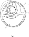
- Fig. 4 is the first end module 3 in perspective, depicting the first axial inner end 3b.
- the cross-sectional shape changes from circular-shaped to a circle sector having a central angle of at most 180 degrees.
- the central angle may for example be in the range of 150-180 degrees.
- the cross-sectional shape changes from crescent-shaped to a circle sector having a central angle of at most 180 degrees.
- the central angle may for example be in the range of 150-180 degrees.
- both the first airflow channel 3c and the second airflow channel 3d will have about the same cross-sectional shape and area when they connect to the rotatable heat or enthalpy exchanger module 5.
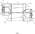
- Fig. 5 illustrates the airflow through the airflow device 1-1.
- a first airflow A flows into the airflow device 1-1 via the fourth airflow channel 7d, passes the rotatable heat or enthalpy exchanger module 5 and exits the airflow device 1-1 via the first airflow channel 3c.
- the first fan 9 sucks air from inside the airflow device 1-1 but could alternatively push air into the airflow device 1-1.
- a second airflow B flows into the airflow device 1-1 via the second airflow channel 3d, passes the rotatable heat or enthalpy exchanger module 5 and exits the airflow device 1-1 via the third airflow channel 7c.
- the second fan 15 sucks air from inside the airflow device 1-1 but could alternatively push air into the airflow device 1-1.
- the first airflow A and the second airflow B flow in opposite directions through the airflow device 1-1.
- Fig. 6 shows another example of a modular airflow device.
- the modular airflow device 1-2 depicted in Fig. 6 is similar to the airflow device 1-1.
- the airflow device 1-2 has a first end module 3 and a rotatable heat or enthalpy exchanger module 5, which are the same as for the airflow device 1-1.
- the airflow device 1-2 has a second end module 7' which is similar to the first and second end modules 3 and 7.
- the second end module 7' does however not have a sleeve 20 for housing an axial fan in the third airflow channel, like the first and second end modules 3 and 7 have.
- the second end module 7' has a third airflow channel which otherwise is configured in the same manner as the third airflow channel 7c of the second end module 7.
- the second end module 7' is not provided with an axial fan in the third airflow channel 7c'.
- the airflow device 1-2 comprises a second fan 19, in the present example a radial fan 19, which has its inlet connected to the third airflow channel at the second axial outer end of the second end module 7'.
- the inlet may be connected directly to the third airflow channel 7c'.
- the second end module 7' also has a fourth airflow channel 7d' which is configured like the fourth airflow channel 7d of the second end module 7.
- the radial fan 19 has a radial fan outlet 21 which in the present example is angled at 90° relative to the central longitudinal axis of the airflow device 1-2.
- the airflow device 1-2 is typically installed in a wall with the radial fan 19 being placed outside the building and the first end module 3 arranged inside the building but could alternatively be installed oppositely.
- Fig. 7 shows the airflow through the airflow device 1-2.
- the airflow device 1-2 comprises a second motor 13 configured to drive the radial fan 19.
- An airflow C enters the airflow device 1-2 through the fourth airflow channel 7d' of the second end module 7'.
- the airflow C then passes through the rotatable heat or enthalpy exchanger module 5 and exits the airflow device 1-2 through the first airflow channel 3c.
- An airflow D which is oppositely directed relative to the airflow C in the airflow device 1-2 enters the airflow device 1-2 through the second airflow channel 3d.
- the airflow D then passes through the rotatable hear exchanger 5 and exits the airflow device through the third airflow channel 7'c into the inlet of the radial fan 19.
- the airflow D then exits the airflow device 1-2 via the radial fan outlet 21.
- the radial fan 19 sucks air from inside the airflow device 1-2 but could alternatively push air into the airflow device 1-2.
- the modular airflow device could be provided with two radial fans, each connected to a respective one of the first end module and the second end module in the same way as illustrated with the radial fan 19 in the example of Figs 6-7 .
- the first fan and the second fan may thus in this case be radial fans.
Landscapes
- Engineering & Computer Science (AREA)
- Chemical & Material Sciences (AREA)
- Combustion & Propulsion (AREA)
- Mechanical Engineering (AREA)
- General Engineering & Computer Science (AREA)
- Structures Of Non-Positive Displacement Pumps (AREA)
Priority Applications (3)
| Application Number | Priority Date | Filing Date | Title |
|---|---|---|---|
| PL21165652.5T PL4067773T3 (pl) | 2021-03-29 | 2021-03-29 | Modułowe urządzenie do przepływu powietrza |
| ES21165652T ES2991879T3 (es) | 2021-03-29 | 2021-03-29 | Dispositivo de flujo de aire modular |
| EP21165652.5A EP4067773B1 (fr) | 2021-03-29 | 2021-03-29 | Dispositif d'écoulement d'air modulaire |
Applications Claiming Priority (1)
| Application Number | Priority Date | Filing Date | Title |
|---|---|---|---|
| EP21165652.5A EP4067773B1 (fr) | 2021-03-29 | 2021-03-29 | Dispositif d'écoulement d'air modulaire |
Publications (3)
| Publication Number | Publication Date |
|---|---|
| EP4067773A1 true EP4067773A1 (fr) | 2022-10-05 |
| EP4067773B1 EP4067773B1 (fr) | 2024-07-17 |
| EP4067773C0 EP4067773C0 (fr) | 2024-07-17 |
Family
ID=75277897
Family Applications (1)
| Application Number | Title | Priority Date | Filing Date |
|---|---|---|---|
| EP21165652.5A Active EP4067773B1 (fr) | 2021-03-29 | 2021-03-29 | Dispositif d'écoulement d'air modulaire |
Country Status (3)
| Country | Link |
|---|---|
| EP (1) | EP4067773B1 (fr) |
| ES (1) | ES2991879T3 (fr) |
| PL (1) | PL4067773T3 (fr) |
Cited By (1)
| Publication number | Priority date | Publication date | Assignee | Title |
|---|---|---|---|---|
| EP4417886A1 (fr) * | 2023-02-17 | 2024-08-21 | Ventilation Systems, Private Joint Stock Company | Unité décentralisée d'alimentation et d'échappement avec récupération de chaleur |
Citations (4)
| Publication number | Priority date | Publication date | Assignee | Title |
|---|---|---|---|---|
| JPS56171317U (fr) * | 1980-05-23 | 1981-12-17 | ||
| US20100155045A1 (en) * | 2008-12-23 | 2010-06-24 | Tai-Her Yang | Rotary type heat exchange apparatus with automatic flow rate exchange modulation |
| CN208282345U (zh) * | 2018-04-11 | 2018-12-25 | 贵州鼎正环保有限公司 | 一种转轮式全热交换器 |
| NO345384B1 (en) * | 2019-02-22 | 2021-01-11 | Peakvent As | Ventilation unit |
-
2021
- 2021-03-29 ES ES21165652T patent/ES2991879T3/es active Active
- 2021-03-29 EP EP21165652.5A patent/EP4067773B1/fr active Active
- 2021-03-29 PL PL21165652.5T patent/PL4067773T3/pl unknown
Patent Citations (4)
| Publication number | Priority date | Publication date | Assignee | Title |
|---|---|---|---|---|
| JPS56171317U (fr) * | 1980-05-23 | 1981-12-17 | ||
| US20100155045A1 (en) * | 2008-12-23 | 2010-06-24 | Tai-Her Yang | Rotary type heat exchange apparatus with automatic flow rate exchange modulation |
| CN208282345U (zh) * | 2018-04-11 | 2018-12-25 | 贵州鼎正环保有限公司 | 一种转轮式全热交换器 |
| NO345384B1 (en) * | 2019-02-22 | 2021-01-11 | Peakvent As | Ventilation unit |
Cited By (2)
| Publication number | Priority date | Publication date | Assignee | Title |
|---|---|---|---|---|
| EP4417886A1 (fr) * | 2023-02-17 | 2024-08-21 | Ventilation Systems, Private Joint Stock Company | Unité décentralisée d'alimentation et d'échappement avec récupération de chaleur |
| US12422154B2 (en) | 2023-02-17 | 2025-09-23 | Limited Liability Company Ventilation Systems | Decentralized supply and exhaust unit with heat recovery |
Also Published As
| Publication number | Publication date |
|---|---|
| ES2991879T3 (es) | 2024-12-05 |
| PL4067773T3 (pl) | 2025-01-20 |
| EP4067773B1 (fr) | 2024-07-17 |
| EP4067773C0 (fr) | 2024-07-17 |
Similar Documents
| Publication | Publication Date | Title |
|---|---|---|
| US5570996A (en) | Compact centrifugal fan | |
| CN201983400U (zh) | 诱导吹出口 | |
| ES2355822T3 (es) | Rueda de ventilador radial, unidad de ventilador y disposición de ventilador radial. | |
| EP2354685B1 (fr) | Dispositif de ventilation et unité d'extérieur doté de celui-ci | |
| EP1924772B1 (fr) | Ventilateur centrifuge d'appareil de traitement d'air | |
| KR101557107B1 (ko) | 다중 벌류트 시로코팬 | |
| TW201723321A (zh) | 通風裝置 | |
| US9242529B2 (en) | Ventilation device | |
| CN106871235A (zh) | 吊顶空调机 | |
| EP4067773B1 (fr) | Dispositif d'écoulement d'air modulaire | |
| US7223068B2 (en) | Housing for axial flow heat-dissipating fan | |
| AU2002217516B2 (en) | Air conditioner | |
| EP1691140A1 (fr) | Système de ventilation et procédé de contrôle associé | |
| US20220372990A1 (en) | Impeller, multi-blade fan, and air-conditioning apparatus | |
| KR101889819B1 (ko) | 루프 벤틸레이터 | |
| EP1726890B1 (fr) | Unité d'intérieur d'un dispositif de conditionnement d'air | |
| CN218120127U (zh) | 用于气流交换的风道组件以及具有其的空调器 | |
| JP2011226407A (ja) | 多翼ファン、空気調和装置及びガイド部材 | |
| CN212657009U (zh) | 吊扇 | |
| EP4703590A1 (fr) | Agencement de ventilateur axial | |
| KR102122255B1 (ko) | 시로코팬 | |
| GB2126652A (en) | Peripheral toroidal blowers | |
| JP2000087896A (ja) | 多翼送風機 | |
| CN113847259B (zh) | 一种贯流风机及具有其的空调器 | |
| KR970062353A (ko) | 반전식 환기팬을 구비한 흡입형 환기팬 장치 |
Legal Events
| Date | Code | Title | Description |
|---|---|---|---|
| PUAI | Public reference made under article 153(3) epc to a published international application that has entered the european phase |
Free format text: ORIGINAL CODE: 0009012 |
|
| STAA | Information on the status of an ep patent application or granted ep patent |
Free format text: STATUS: THE APPLICATION HAS BEEN PUBLISHED |
|
| AK | Designated contracting states |
Kind code of ref document: A1 Designated state(s): AL AT BE BG CH CY CZ DE DK EE ES FI FR GB GR HR HU IE IS IT LI LT LU LV MC MK MT NL NO PL PT RO RS SE SI SK SM TR |
|
| STAA | Information on the status of an ep patent application or granted ep patent |
Free format text: STATUS: REQUEST FOR EXAMINATION WAS MADE |
|
| 17P | Request for examination filed |
Effective date: 20230404 |
|
| RBV | Designated contracting states (corrected) |
Designated state(s): AL AT BE BG CH CY CZ DE DK EE ES FI FR GB GR HR HU IE IS IT LI LT LU LV MC MK MT NL NO PL PT RO RS SE SI SK SM TR |
|
| GRAP | Despatch of communication of intention to grant a patent |
Free format text: ORIGINAL CODE: EPIDOSNIGR1 |
|
| STAA | Information on the status of an ep patent application or granted ep patent |
Free format text: STATUS: GRANT OF PATENT IS INTENDED |
|
| RIC1 | Information provided on ipc code assigned before grant |
Ipc: F24F 13/20 20060101ALN20230918BHEP Ipc: F24F 12/00 20060101ALI20230918BHEP Ipc: F24F 13/08 20060101AFI20230918BHEP |
|
| INTG | Intention to grant announced |
Effective date: 20231010 |
|
| GRAJ | Information related to disapproval of communication of intention to grant by the applicant or resumption of examination proceedings by the epo deleted |
Free format text: ORIGINAL CODE: EPIDOSDIGR1 |
|
| STAA | Information on the status of an ep patent application or granted ep patent |
Free format text: STATUS: REQUEST FOR EXAMINATION WAS MADE |
|
| GRAP | Despatch of communication of intention to grant a patent |
Free format text: ORIGINAL CODE: EPIDOSNIGR1 |
|
| STAA | Information on the status of an ep patent application or granted ep patent |
Free format text: STATUS: GRANT OF PATENT IS INTENDED |
|
| INTC | Intention to grant announced (deleted) | ||
| RIC1 | Information provided on ipc code assigned before grant |
Ipc: F24F 13/20 20060101ALN20240220BHEP Ipc: F24F 12/00 20060101ALI20240220BHEP Ipc: F24F 13/08 20060101AFI20240220BHEP |
|
| INTG | Intention to grant announced |
Effective date: 20240305 |
|
| GRAS | Grant fee paid |
Free format text: ORIGINAL CODE: EPIDOSNIGR3 |
|
| GRAA | (expected) grant |
Free format text: ORIGINAL CODE: 0009210 |
|
| STAA | Information on the status of an ep patent application or granted ep patent |
Free format text: STATUS: THE PATENT HAS BEEN GRANTED |
|
| AK | Designated contracting states |
Kind code of ref document: B1 Designated state(s): AL AT BE BG CH CY CZ DE DK EE ES FI FR GB GR HR HU IE IS IT LI LT LU LV MC MK MT NL NO PL PT RO RS SE SI SK SM TR |
|
| REG | Reference to a national code |
Ref country code: CH Ref legal event code: EP |
|
| REG | Reference to a national code |
Ref country code: DE Ref legal event code: R096 Ref document number: 602021015675 Country of ref document: DE |
|
| REG | Reference to a national code |
Ref country code: IE Ref legal event code: FG4D |
|
| U01 | Request for unitary effect filed |
Effective date: 20240813 |
|
| U07 | Unitary effect registered |
Designated state(s): AT BE BG DE DK EE FI FR IT LT LU LV MT NL PT SE SI Effective date: 20240826 |
|
| REG | Reference to a national code |
Ref country code: ES Ref legal event code: FG2A Ref document number: 2991879 Country of ref document: ES Kind code of ref document: T3 Effective date: 20241205 |
|
| PG25 | Lapsed in a contracting state [announced via postgrant information from national office to epo] |
Ref country code: GR Free format text: LAPSE BECAUSE OF FAILURE TO SUBMIT A TRANSLATION OF THE DESCRIPTION OR TO PAY THE FEE WITHIN THE PRESCRIBED TIME-LIMIT Effective date: 20241018 |
|
| PG25 | Lapsed in a contracting state [announced via postgrant information from national office to epo] |
Ref country code: IS Free format text: LAPSE BECAUSE OF FAILURE TO SUBMIT A TRANSLATION OF THE DESCRIPTION OR TO PAY THE FEE WITHIN THE PRESCRIBED TIME-LIMIT Effective date: 20241117 |
|
| PG25 | Lapsed in a contracting state [announced via postgrant information from national office to epo] |
Ref country code: HR Free format text: LAPSE BECAUSE OF FAILURE TO SUBMIT A TRANSLATION OF THE DESCRIPTION OR TO PAY THE FEE WITHIN THE PRESCRIBED TIME-LIMIT Effective date: 20240717 |
|
| PG25 | Lapsed in a contracting state [announced via postgrant information from national office to epo] |
Ref country code: RS Free format text: LAPSE BECAUSE OF FAILURE TO SUBMIT A TRANSLATION OF THE DESCRIPTION OR TO PAY THE FEE WITHIN THE PRESCRIBED TIME-LIMIT Effective date: 20241017 |
|
| PG25 | Lapsed in a contracting state [announced via postgrant information from national office to epo] |
Ref country code: RS Free format text: LAPSE BECAUSE OF FAILURE TO SUBMIT A TRANSLATION OF THE DESCRIPTION OR TO PAY THE FEE WITHIN THE PRESCRIBED TIME-LIMIT Effective date: 20241017 Ref country code: IS Free format text: LAPSE BECAUSE OF FAILURE TO SUBMIT A TRANSLATION OF THE DESCRIPTION OR TO PAY THE FEE WITHIN THE PRESCRIBED TIME-LIMIT Effective date: 20241117 Ref country code: HR Free format text: LAPSE BECAUSE OF FAILURE TO SUBMIT A TRANSLATION OF THE DESCRIPTION OR TO PAY THE FEE WITHIN THE PRESCRIBED TIME-LIMIT Effective date: 20240717 Ref country code: GR Free format text: LAPSE BECAUSE OF FAILURE TO SUBMIT A TRANSLATION OF THE DESCRIPTION OR TO PAY THE FEE WITHIN THE PRESCRIBED TIME-LIMIT Effective date: 20241018 |
|
| PG25 | Lapsed in a contracting state [announced via postgrant information from national office to epo] |
Ref country code: SM Free format text: LAPSE BECAUSE OF FAILURE TO SUBMIT A TRANSLATION OF THE DESCRIPTION OR TO PAY THE FEE WITHIN THE PRESCRIBED TIME-LIMIT Effective date: 20240717 |
|
| U20 | Renewal fee for the european patent with unitary effect paid |
Year of fee payment: 5 Effective date: 20250317 |
|
| PG25 | Lapsed in a contracting state [announced via postgrant information from national office to epo] |
Ref country code: CZ Free format text: LAPSE BECAUSE OF FAILURE TO SUBMIT A TRANSLATION OF THE DESCRIPTION OR TO PAY THE FEE WITHIN THE PRESCRIBED TIME-LIMIT Effective date: 20240717 |
|
| PG25 | Lapsed in a contracting state [announced via postgrant information from national office to epo] |
Ref country code: SK Free format text: LAPSE BECAUSE OF FAILURE TO SUBMIT A TRANSLATION OF THE DESCRIPTION OR TO PAY THE FEE WITHIN THE PRESCRIBED TIME-LIMIT Effective date: 20240717 |
|
| PLBE | No opposition filed within time limit |
Free format text: ORIGINAL CODE: 0009261 |
|
| STAA | Information on the status of an ep patent application or granted ep patent |
Free format text: STATUS: NO OPPOSITION FILED WITHIN TIME LIMIT |
|
| 26N | No opposition filed |
Effective date: 20250422 |
|
| PGFP | Annual fee paid to national office [announced via postgrant information from national office to epo] |
Ref country code: ES Payment date: 20250403 Year of fee payment: 5 |
|
| PG25 | Lapsed in a contracting state [announced via postgrant information from national office to epo] |
Ref country code: MC Free format text: LAPSE BECAUSE OF FAILURE TO SUBMIT A TRANSLATION OF THE DESCRIPTION OR TO PAY THE FEE WITHIN THE PRESCRIBED TIME-LIMIT Effective date: 20240717 |
|
| REG | Reference to a national code |
Ref country code: CH Ref legal event code: H13 Free format text: ST27 STATUS EVENT CODE: U-0-0-H10-H13 (AS PROVIDED BY THE NATIONAL OFFICE) Effective date: 20251024 |
|
| PG25 | Lapsed in a contracting state [announced via postgrant information from national office to epo] |
Ref country code: CH Free format text: LAPSE BECAUSE OF NON-PAYMENT OF DUE FEES Effective date: 20250331 |
|
| PG25 | Lapsed in a contracting state [announced via postgrant information from national office to epo] |
Ref country code: IE Free format text: LAPSE BECAUSE OF NON-PAYMENT OF DUE FEES Effective date: 20250329 |
|
| PGFP | Annual fee paid to national office [announced via postgrant information from national office to epo] |
Ref country code: GB Payment date: 20260317 Year of fee payment: 6 |
|
| PGFP | Annual fee paid to national office [announced via postgrant information from national office to epo] |
Ref country code: NO Payment date: 20260323 Year of fee payment: 6 |
|
| PG25 | Lapsed in a contracting state [announced via postgrant information from national office to epo] |
Ref country code: RO Free format text: LAPSE BECAUSE OF FAILURE TO SUBMIT A TRANSLATION OF THE DESCRIPTION OR TO PAY THE FEE WITHIN THE PRESCRIBED TIME-LIMIT Effective date: 20240717 |
|
| U20 | Renewal fee for the european patent with unitary effect paid |
Year of fee payment: 6 Effective date: 20260311 |
|
| PGFP | Annual fee paid to national office [announced via postgrant information from national office to epo] |
Ref country code: PL Payment date: 20260304 Year of fee payment: 6 |