EP4067910B1 - Prédiction de défaillance et/ou estimation de la durée de vie utile restante d'un dispositif de chauffage de sonde de données d'air - Google Patents
Prédiction de défaillance et/ou estimation de la durée de vie utile restante d'un dispositif de chauffage de sonde de données d'air Download PDFInfo
- Publication number
- EP4067910B1 EP4067910B1 EP22165490.8A EP22165490A EP4067910B1 EP 4067910 B1 EP4067910 B1 EP 4067910B1 EP 22165490 A EP22165490 A EP 22165490A EP 4067910 B1 EP4067910 B1 EP 4067910B1
- Authority
- EP
- European Patent Office
- Prior art keywords
- heating element
- resistive heating
- remaining
- electrical
- operating power
- Prior art date
- Legal status (The legal status is an assumption and is not a legal conclusion. Google has not performed a legal analysis and makes no representation as to the accuracy of the status listed.)
- Active
Links
Images


Classifications
-
- G—PHYSICS
- G01—MEASURING; TESTING
- G01R—MEASURING ELECTRIC VARIABLES; MEASURING MAGNETIC VARIABLES
- G01R31/00—Arrangements for testing electric properties; Arrangements for locating electric faults; Arrangements for electrical testing characterised by what is being tested not provided for elsewhere
- G01R31/50—Testing of electric apparatus, lines, cables or components for short-circuits, continuity, leakage current or incorrect line connections
- G01R31/56—Testing of electric apparatus
-
- G—PHYSICS
- G01—MEASURING; TESTING
- G01P—MEASURING LINEAR OR ANGULAR SPEED, ACCELERATION, DECELERATION, OR SHOCK; INDICATING PRESENCE, ABSENCE, OR DIRECTION, OF MOVEMENT
- G01P21/00—Testing or calibrating of apparatus or devices covered by the preceding groups
- G01P21/02—Testing or calibrating of apparatus or devices covered by the preceding groups of speedometers
- G01P21/025—Testing or calibrating of apparatus or devices covered by the preceding groups of speedometers for measuring speed of fluids; for measuring speed of bodies relative to fluids
-
- G—PHYSICS
- G01—MEASURING; TESTING
- G01R—MEASURING ELECTRIC VARIABLES; MEASURING MAGNETIC VARIABLES
- G01R31/00—Arrangements for testing electric properties; Arrangements for locating electric faults; Arrangements for electrical testing characterised by what is being tested not provided for elsewhere
- G01R31/50—Testing of electric apparatus, lines, cables or components for short-circuits, continuity, leakage current or incorrect line connections
- G01R31/52—Testing for short-circuits, leakage current or ground faults
-
- B—PERFORMING OPERATIONS; TRANSPORTING
- B64—AIRCRAFT; AVIATION; COSMONAUTICS
- B64D—EQUIPMENT FOR FITTING IN OR TO AIRCRAFT; FLIGHT SUITS; PARACHUTES; ARRANGEMENT OR MOUNTING OF POWER PLANTS OR PROPULSION TRANSMISSIONS IN AIRCRAFT
- B64D15/00—De-icing or preventing icing on exterior surfaces of aircraft
- B64D15/12—De-icing or preventing icing on exterior surfaces of aircraft by electric heating
-
- B—PERFORMING OPERATIONS; TRANSPORTING
- B64—AIRCRAFT; AVIATION; COSMONAUTICS
- B64D—EQUIPMENT FOR FITTING IN OR TO AIRCRAFT; FLIGHT SUITS; PARACHUTES; ARRANGEMENT OR MOUNTING OF POWER PLANTS OR PROPULSION TRANSMISSIONS IN AIRCRAFT
- B64D45/00—Aircraft indicators or protectors not otherwise provided for
- B64D2045/0085—Devices for aircraft health monitoring, e.g. monitoring flutter or vibration
-
- B—PERFORMING OPERATIONS; TRANSPORTING
- B64—AIRCRAFT; AVIATION; COSMONAUTICS
- B64D—EQUIPMENT FOR FITTING IN OR TO AIRCRAFT; FLIGHT SUITS; PARACHUTES; ARRANGEMENT OR MOUNTING OF POWER PLANTS OR PROPULSION TRANSMISSIONS IN AIRCRAFT
- B64D43/00—Arrangements or adaptations of instruments
- B64D43/02—Arrangements or adaptations of instruments for indicating aircraft speed or stalling conditions
-
- G—PHYSICS
- G01—MEASURING; TESTING
- G01F—MEASURING VOLUME, VOLUME FLOW, MASS FLOW OR LIQUID LEVEL; METERING BY VOLUME
- G01F25/00—Testing or calibration of apparatus for measuring volume, volume flow or liquid level or for metering by volume
- G01F25/10—Testing or calibration of apparatus for measuring volume, volume flow or liquid level or for metering by volume of flowmeters
-
- G—PHYSICS
- G01—MEASURING; TESTING
- G01P—MEASURING LINEAR OR ANGULAR SPEED, ACCELERATION, DECELERATION, OR SHOCK; INDICATING PRESENCE, ABSENCE, OR DIRECTION, OF MOVEMENT
- G01P13/00—Indicating or recording presence, absence, or direction, of movement
- G01P13/02—Indicating direction only, e.g. by weather vane
- G01P13/025—Indicating direction only, e.g. by weather vane indicating air data, i.e. flight variables of an aircraft, e.g. angle of attack, side slip, shear, yaw
-
- G—PHYSICS
- G01—MEASURING; TESTING
- G01P—MEASURING LINEAR OR ANGULAR SPEED, ACCELERATION, DECELERATION, OR SHOCK; INDICATING PRESENCE, ABSENCE, OR DIRECTION, OF MOVEMENT
- G01P5/00—Measuring speed of fluids, e.g. of air stream; Measuring speed of bodies relative to fluids, e.g. of ship, of aircraft
- G01P5/14—Measuring speed of fluids, e.g. of air stream; Measuring speed of bodies relative to fluids, e.g. of ship, of aircraft by measuring differences of pressure in the fluid
- G01P5/16—Measuring speed of fluids, e.g. of air stream; Measuring speed of bodies relative to fluids, e.g. of ship, of aircraft by measuring differences of pressure in the fluid using Pitot tubes, e.g. Machmeter
- G01P5/165—Arrangements or constructions of Pitot tubes
Definitions
- Air data probes typically include resistive heater elements to prevent operational issues relating to in-flight ice buildup.
- One of the most common types of failures in air data probes is failure of the resistive heating element. The ability to predict a future failure of the resistive heating element in air data probes would permit and facilitate pre-emptive maintenance to be performed without causing flight delays.
- the heater element in an air data probe often consists of a resistive heater wire surrounded by an insulator and encapsulated within a metallic sheath.
- the insulator creates a very high electrical resistance between the metallic sheath (often electrically connected to the body of the probe) and the heater wire itself.
- the presence of the heater wire, insulator, and metallic sheath also creates a capacitance between the sheath and the heater wire.
- the combination of the insulation resistance and the wire-sheath capacitance creates a path for leakage current to flow from the heater wire to the sheath when a voltage is applied to the heating element.
- EP 3379266 A1 discloses a probe system for an aircraft having a probe that includes a heater provided with a resistive heating element.
- An operational current is provided to the resistive heating element for heating the probe.
- First and second current sensors sense first and second currents through the resistive heating element.
- a control circuit determines a leakage current based on the first and second currents, and determines the remaining useful life the probe based on the leakage current over time.
- Apparatus and associated methods relate to a system for predicting failure and/or estimating remaining useful life of a resistive heating element of an air data probe.
- a system for predicting failure and/or estimating remaining useful life of a resistive heating element of an air data probe is provided according to claim 1.
- the system includes an electrical power source, a first electrical sensor, a second electrical sensor, a signal comparator and a remaining-life prediction engine.
- the electrical power source is configured to provide AC electrical operating power to the resistive heating element during normal operation of the air data probe.
- the first electrical sensor is configured to sense AC voltage and/or AC current of the AC electrical operating power provided to the resistive heating element.
- the second electrical sensor is configured to sense AC leakage current between the resistive heating element and a conductive sheath surrounding the electrical heating element.
- the signal comparator is configured to determine a phase relation between the AC leakage current as sensed by the second electrical sensor and the AC voltage and/or AC current of the electrical operating power provided to the resistive heating element as sensed by the first electrical sensor.
- the remaining-life prediction engine is configured to estimate the remaining life of the resistive heating element based on the phase relation determined.
- a method for predicting failure of a resistive heating element of an air data probe includes providing, via an AC electrical power source, AC electrical operating power to the resistive heating element.
- the method includes sensing, via a first electrical sensor, AC voltage and/or AC current of the AC electrical operating power provided to the resistive heating element.
- the method includes sensing, via a second electrical sensor, AC leakage current between the resistive heating element and a conductive sheath surrounding the electrical heating element.
- the method includes determining, via a signal comparator, a phase relation between the AC leakage current as sensed by the second electrical sensor and the AC voltage and/or AC current of the AC electrical operating power provided to the resistive heating element.
- the method also includes estimating, via a remaining-life prediction engine, the remaining life of the resistive heating element based on the phase relation determined.
- Apparatus and associated methods relate to predicting failure and/or estimating remaining useful life of an air-data-probe heater. Failure is predicted or useful life is estimated based on an electrical metric of the electrical operating power provided to a resistive heating element of the air-data-probe heater.
- the electrical metric of the air data probe heater is one or more of: i) phase relation between voltage across the resistive heating element and leakage current, which is conducted from the resistive heating element to a conductive sheath surrounding the resistive heating element; ii) a time-domain profile of leakage current through the heating element insulation during a full power cycle; and/or iii) high-frequency components of the electrical current conducted by the resistive heating element and/or the voltage across the resistive heating element.
- FIG. 1 is a schematic diagram of an aircraft equipped with a system for predicting failure and/or estimating remaining useful life of an air-data-probe heater.
- aircraft 10 includes engine 12, which drives electrical generator 14 so as to provide electrical operating power to various powered electrical systems aboard aircraft 10.
- Aircraft 10 is also equipped with various air-data-probe sensors, including air-data-probe sensor 16.
- Air-data-probe sensor 16 is an electrical system powered by aircraft power distribution system 18.
- Air-data-probe sensor 16 receives operating power from aircraft power source 18 via electrical operating power cable 20.
- Aircraft 10 is also equipped with health monitoring system 22, which predicts failure and/or estimates remaining useful life of resistive heating element 24 of air-data-probe sensor 16.
- health monitoring system 22 is configured to predict failure and/or estimate remaining useful life of resistive heating element 24 based on an electrical metric of electrical operating power provided to resistive heating element 24.
- air-data-probe sensor 16 senses air pressure.
- Various air-data-probe sensors sense air pressure for the purpose of determining various air data metrics, such as airspeed, altitude, angle-of-attack, etc.
- air-data-probe sensor 16 is a Pitot tube airspeed detector that includes resistive heating element 24, and ram pressure air-data-probe sensor 26.
- Resistive heating element 24 is configured to prevent icing of air-data-probe sensor 16 when aircraft 10 is operating in an atmosphere in which ice accretion can occur.
- Health monitoring system 22 includes electrical power source 28, electrical sensor 30, and remaining life prediction engine 32.
- Electrical power source 28 converts electrical power received from aircraft power source 18 into one or more different power configurations for use by air-data-probe sensor 16 and/or resistive heating element 24.
- Electrical sensor 30 is configured to sense an electrical metric of the operating power provided to resistive heating element 24.
- the electrical metric sensed by electrical sensor 30 is at least one of: i) phase relation between electrical current conducted from the resistive heating element to its surrounding conductive sheath and voltage across the resistive heating element; ii) a time-domain profile during a full power cycle of the leakage current conducted from the resistive heating element to its surrounding conductive sheath or the voltage across the resistive heating element; and/or iii) high-frequency components of the electrical current conducted by the resistive heating element and/or of the voltage across the resistive heating element.
- Remaining life prediction engine 32 predicts failure and/or estimates remaining useful life of resistive heating element 24 based on the electrical metric sensed by electrical sensor 30.
- Each of the various electrical metrics described above can be indicative of health of resistive heating element 24.
- Each of these described electrical metrics with be further described below along with the relation these electrical metrics have with the health of resistive heating element 24, with reference to FIGS. 2-8 .
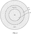
- FIG. 2 is a graph of a cross-sectional diagram of a resistive heating element along with coaxial insulative material and a coaxial conductive sheath.
- Resistive heating element 24 is designed to have a particular resistance-temperature relation.
- the temperature of resistive heating element 24 can be determined based on a determination of electrical resistance of resistive heating element 24.
- electrical resistance of resistive heating element 24 can be monotonically increasing with increasing temperature.
- temperature of resistive heating element 24 is a function of resistance of resistive heating element 24.
- Coaxial insulative material 34 provides electrical insulation between resistive heating element 24 and surrounding coaxial conductive sheath 36. Such electrical insulation permits resistive heating element 24 to be electrically biased independently of coaxial conductive sheath 36, which is typically grounded.
- FIG. 3 is simplified schematic circuit demonstrating leakage behavior of a resistive heating element biased by an electrical power source.
- electrical power source 28 provides operating power to resistive heating element 24.
- Resistive heating element 24 has leakage path 38 at a particular location along a length of resistive heating element 24.
- Simplified lumped parameter model of resistive heating element 24 has portions on either side of the particular location along its length, as represented by first heating resistor R H1 and second heating resistor R H2 .
- Leakage path 38 is modeled as leakage resistance R LKG in parallel with leakage capacitance C LKG .
- phase angle will become less out of phase, as the coupling between resistive heating element 24 and coaxial conductive sheath 36, becomes more conductive (i.e., leakage resistance R LKG become smaller) and less capacitive.
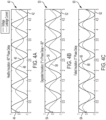
- FIGS. 4A-4C are graphs of AC electrical voltage of operating power provided to a resistive heating element and leakage current, for various health conditions of a resistive heating element.
- graph 40 includes horizontal axis 42, vertical axis 44, voltage-time relation 46, and current-time relation 48.
- Horizontal axis 42 is indicative of time.
- Vertical axis 44 is indicative of voltage and leakage current.
- Voltage-time relation 46 depicts temporal behavior of voltage across resistive heating element 24 (as depicted in FIG. 3 ).
- electrical power source 28 provides AC operating power to resistive heating element 24.
- leakage current-time relation 48 is mostly out of phase with voltage-time relation 46.
- graph 50 includes horizontal axis 52, vertical axis 54, voltage-time relation 56, and leakage current-time relation 58.
- Horizontal axis 52 is again indicative of time.
- Vertical axis 54 is again indicative of voltage and leakage current.
- Voltage-time relation 56 depicts temporal behavior of voltage across resistive heating element 24 (as depicted in FIG. 3 ).
- electrical power source 28 provides AC operating power to resistive heating element 24.
- leakage current-time relation 58 is not in phase with voltage-time relation 56.
- Leakage current-time relation 58 leads voltage-time relation 56 by about 45 degrees. Such a relation can occur when the impedance of leakage capacitor C LKG is comparable to impedance of the leakage resistor R LKG at frequency of the AC operating power.
- phase relation is indicative of some degradation of insulative material 34.
- graph 60 includes horizontal axis 62, vertical axis 64, voltage-time relation 66, and leakage current-time relation 68.
- Horizontal axis 62 is again indicative of time.
- Vertical axis 64 is again indicative of voltage and leakage current.
- Voltage-time relation 66 depicts temporal behavior of voltage across resistive heating element 24 (as depicted in FIG. 3 ).
- electrical power source 28 provides AC operating power to resistive heating element 24.
- leakage current-time relation 48 is mostly in phase with voltage-time relation 66. Such a relation occurs when insulative material 34 becomes compromised (e.g., very thin or non-existent in places).
- Temperature also affects the phase relation of the electrical current and the voltage for a degraded resistive heating element.
- a temperature dependency can occur for a variety of reasons. For example, as resistive heating element 24 heats up, leakage conductance (i.e., inverse of R LKG ) can decrease as moisture is driven away out of coaxial insulative material 34. This decrease in leakage conductance 1/R LKG can cause the phase relation between leakage current and voltage across resistive heating element 24 to become somewhat more out of phase (e.g., between a 10 and 30 degree change from its initial cold temperature phase relation). Also, a temperature dependency can occur because the insulative quality of insulative material 34 can change as a function of temperature. Thus, understanding the normal temperature dependency of the leakage current-voltage phase relation can help one to identify when such a phase relation is abnormal.
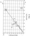
- FIG. 5 is a graph of leakage current to voltage phase relationship at the operating power provided to a resistive heating element as a function of temperature.
- graph 70 includes horizontal axis 72, vertical axis 74, and leakage current-voltage phase relation 76.
- Horizontal axis 72 is indicative of temperature.
- Vertical axis 74 is indicative of phase delay angle of the leakage current with regard to the voltage of the operating power provided to resistive heating element 24 (depicted in FIG. 2 ).
- Leakage current-voltage phase relation 76 indicates that at low temperatures, the electrical current is delayed by about -90 degrees (i.e., the electrical current leads the voltage by about 90 degrees). As temperature increases, the phase delay of the leakage current increases (i.e., decreases in negative magnitude).
- phase relation is indicative of a probe, in which insulative material 34 has been degraded.
- changes in the phase relation due to heating of resistive heating element is typically modest (e.g., between 10 and 30 degrees).
- the phase delay of the leakage current crosses zero degrees for the resistive heating element with degraded insulative material, as depicted in the figure.
- some embodiments of health monitoring system 22 use leakage current-voltage phase data acquired at a predetermined standard temperature.
- Other embodiments of health monitoring system 22 compare measurements of leakage current-voltage phase data with a known predetermined leakage current-voltage phase relation, such as, for example, leakage current-voltage phase relation 76.
- FIG. 6 is a graph of leakage current phase delay data acquired over a lifetime of a resistive heating element.
- graph 80 includes horizontal axis 82, vertical axis 84, leakage current data 86 and leakage current projection 88.
- Horizontal axis 82 is indicative of heater power cycle number.
- Vertical axis 84 is indicative of leakage current phase delay. Every time that the resistive heating element 24 is power cycled (i.e., turned on and operated), data is collected at a predetermined operating temperature, as the temperature of resistive heating element 24 crosses that predetermined operating temperature. This acquired data is represented on graph 80 as leakage current data 86.
- a trend line is fit to leakage current data 86 and projected as leakage current phase delay projection 88 on graph 80.
- the number of remaining power cycles before leakage current phase delay projection 88 crosses a predetermined threshold can indicate a remaining useful life of resistive heating element 24.
- the predetermined threshold is zero degrees, but such a threshold need not be zero degrees, depending on the lifetime testing margin of the particular embodiment.
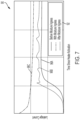
- FIG. 7 is a graph of various start up behaviors for leakage current from a resistive heating element.
- graph 90 includes horizontal axis 92, vertical axis 94, and leakage current-time relations 96A-96C.
- Horizontal axis 92 is indicative of time measured from initial provision of power to resistive heating element 24.
- Vertical axis 94 is indicative of leakage current measured between resistive heating element 24 and coaxial conductive sheath 38.
- electrical power source 28 provides AC operating power to resistive heating element 24.
- RMS values of current and power can be monitored and start up behavior of these monitored electrical metrics are indicative of health of coaxial conductive sheath 36 and/or coaxial insulative material 34.
- An increase in leakage current exhibitions of noise fluctuations can indicate a presence of moisture, thus indicating damage to either coaxial conductive sheath 36 and/or coaxial insulative material 34.
- DC operating power is provided to resistive heating element 24.
- Such leakage current can have start-up behavior that varies in response to health condition and in response to presence or absence of moisture.
- Current-time relations 96A-96C represent leakage current of resistive heating element 24 as measured at start-up time for three consequent start-up cycles representing different moisture content conditions that range from moisture to less moisture to no moisture.
- Coaxial conductive sheath 36 is configured to provide a physical barrier between resistive heating element 24 and coaxial insulative material 32 from the atmospheric environment. Moisture in the atmospheric environment can cause degradation to each of coaxial insulative material 32 and resistive heating element 24, should such elements be exposed to moisture in the atmosphere. The integrity of the barrier presented by coaxial conductive sheath 36 can become compromised with age, though. And should coaxial conductive sheath 36 become compromised, leakage currents can increase as a result of degradation (e.g., thinning, cracking, etc.) of coaxial insulative material 34. Such degradation can be due to a compromised coaxial conductive sheath 36, which, when compromised, can permit the ingress of moisture into coaxial insulative material 34 and resistive heating element 24.
- degradation e.g., thinning, cracking, etc.
- Current-time relation 96A represents the power-cycle leakage current profile for resistive heating element 24 before moisture ingress into coaxial insulative material 34 and/or resistive heating element 24.
- Current-time relation 96C represents the start-up leakage current profile for resistive heating element 24 after moisture ingress into coaxial insulative material 34 and/or resistive heating element 24. Such moisture ingress assists the conduction of electrical currents, thereby increasing the level of leakage current until thermal heating element 34 heats up enough to drive away the moisture present.
- the steady-state current asymptote is higher for current-time relation 96C than the steady-state current asymptote for current-time relation 96A.
- Current-time relation 96B represents the power-cycle leakage current profile for resistive heating element 24 after moisture ingress into coaxial insulative material 34 and/or resistive heating element 24 (e.g., after the moisture has been driven out of coaxial insulative material 34 by temperatures generated by resistive heating element 24).
- the steady-state current asymptote remains higher for current-time relation 96B than the steady-state current asymptote for current-time relation 96A.
- FIG. 8 is a graph of high-frequency noise in AC electrical currents provided to a resistive heating element showing degradation.
- graph 100 includes horizontal axis 102, vertical axis 104, and electrical current-time relations 106 and 108.
- Horizontal axis 102 is indicative of time.
- Vertical axis 104 is indicative of amplitude of electrical current of operating power provided to resistive heating element 24.
- Electrical current-time relation 106 depicts temporal behavior of electrical current of the operating power provided to resistive heating element 24 (as depicted in FIG.
- electrical current-time relation 108 depicts temporal behavior of electrical current of the operating power provided to resistive heating element 24 (as depicted in FIG. 3 ), for a resistive heating element with degraded insulative material 34.
- the main difference between electrical current-time relation 106 and electrical current-time relation 108 is the high-frequency behavior (i.e., at frequencies high in comparison with the frequency of the AC operating power).
- Electrical current-time relation 108 has discernable high-frequency noise superimposed on the AC signal, whereas electrical current-time relation 106 has no discernable high-frequency noise. Such high-frequency noise can be indicative of a corroded resistive heating element 24.
- Current-time relation 108 has such high-frequency components indicative of degradation (e.g., micro cracks) of resistive heating element 24 superimposed on the AC current waveform.
- High-frequency components in current-time relation 108 can be caused by other factors as well. For example, any high-frequency components in voltage of the operating power provided to resistive heating element 24 will be replicated in current-time relation 106 for resistive heating element 34 that are not degraded. Therefore, sensing high-frequency components of both voltage-time relation 106 and current-time relation 108 can be used to determine if such components are present in but one of the two electrical metrics. For example, a ratio can be made of the high-frequency components of current-time relation 108 to the high-frequency components of voltage of operating power provided to resistive heating element 24. Then, such a ratio can be compared with a predetermined threshold value. If the ratio is greater than the predetermined threshold value, remaining life prediction engine 32 can generate a signal indicative of the event. A log of such incidences of such a comparison can be maintained. Remaining useful life can be determined based on such a log.
- Such high-frequency components can be sensed, for example, by taking a derivative of voltage of operating power provided to resistive heating element 24 and/or current-time relation 108.
- the operation of taking the derivative amplifies high-frequency components above lower-frequency components.
- a ratio of the derivatives of the current-time relation and the voltage-time relation can then be compared with a predetermined threshold. If the ratio is greater than the predetermined threshold, such a comparison can be indicative of micro cracks in resistive heating element 24.
- Remaining life prediction engine 32 can make such calculations (e.g., take the derivatives, calculate the ratio, and make the comparison, etc.) in various ways.
- remaining life prediction engine 32 can include a processor, a programmable logic array, or any other type of programmable device. In some embodiments, remaining life prediction engine 32 can be configured to perform all of the operations using discrete circuitry.
Landscapes
- Physics & Mathematics (AREA)
- General Physics & Mathematics (AREA)
- Engineering & Computer Science (AREA)
- Power Engineering (AREA)
- Aviation & Aerospace Engineering (AREA)
- Testing Of Short-Circuits, Discontinuities, Leakage, Or Incorrect Line Connections (AREA)
- Testing Or Measuring Of Semiconductors Or The Like (AREA)
- Control Of Resistance Heating (AREA)
Claims (14)
- Système permettant de prédire une défaillance et/ou d'estimer la durée de vie utile restante d'un élément chauffant résistif d'une sonde de données d'air, le système comprenant :une source d'énergie électrique (28) configurée pour fournir une énergie électrique CA à l'élément chauffant résistif pendant le fonctionnement normal de la sonde de données d'air ;un premier capteur électrique (30) configuré pour détecter la tension alternative et/ou le courant alternatif de l'énergie électrique de fonctionnement alternative fournie à l'élément chauffant résistif ;un second capteur électrique (30) configuré pour détecter un courant de fuite CA entre l'élément chauffant résistif et une gaine conductrice entourant l'élément chauffant électrique ;un comparateur de signaux configuré pour déterminer une relation de phase entre le courant de fuite CA tel que détecté par le second capteur électrique et la tension et/ou le courant CA de l'énergie électrique CA fournie à l'élément chauffant résistif tel que détecté par le premier capteur électrique ; etun moteur de prédiction de durée de vie restante (32) configuré pour estimer la durée de vie restante de l'élément chauffant résistif sur la base de la relation de phase déterminée.
- Système selon la revendication 1, dans lequel le moteur de prédiction de durée de vie restante (32) est configuré pour estimer la durée de vie restante de l'élément chauffant résistif en estimant un temps restant pendant lequel une énergie de fonctionnement électrique CA peut être fournie à l'élément chauffant résistif jusqu'à ce que la relation de phase déterminée franchisse un seuil de relation de phase prédéterminé.
- Système selon la revendication 1, dans lequel le moteur de prédiction de durée de vie restante (32) est configuré pour calculer une température d'élément de l'élément chauffant sur la base, au moins en partie, de l'énergie de fonctionnement électrique CA fournie à l'élément chauffant résistif.
- Système selon la revendication 3, comprenant également :une minuterie pour marquer le temps de fonctionnement de l'élément chauffant à partir d'un temps de fonctionnement initial lorsque l'énergie électrique de fonctionnement en courant alternatif est initialement fournie au capteur de température résistif,dans lequel le moteur de prédiction de durée de vie restante (32) calcule la température de l'élément en fonction, au moins en partie, du temps de fonctionnement de l'élément chauffant marqué.
- Système selon la revendication 3, dans lequel le moteur de prédiction de durée de vie restante (32) est configuré pour comparer la température de l'élément calculée avec un seuil de température prédéterminé.
- Système selon la revendication 5, dans lequel le moteur de prédiction de durée de vie restante (32) est configuré pour estimer la durée de vie restante de l'élément chauffant résistif sur la base de la relation de phase déterminée lorsque la température de l'élément calculée se situe dans une plage de température delta du seuil de température prédéterminé, ou dans lequel le moteur de prédiction de durée de vie restante (32) est configuré pour estimer la durée de vie restante de l'élément chauffant résistif sur la base de la relation de phase tombant en dessous d'une différence de phase de 45°.
- Système selon la revendication 5, dans lequel le courant de fuite est détecté lorsque la température de l'élément calculée dépasse ou se situe dans une plage de température delta du seuil de température prédéterminé et est enregistré dans un journal de courant de fuite.
- Système selon la revendication 7, dans lequel le moteur de prédiction de durée de vie restante (32) est configuré pour estimer la durée de vie restante de l'élément chauffant résistif sur la base d'une courbe de projection du journal de courant de fuite, et éventuellement dans lequel le moteur de prédiction de durée de vie restante (32) est configuré pour estimer la durée de vie restante comme étant le temps restant pendant lequel une énergie de fonctionnement électrique peut être fournie à l'élément chauffant résistif auquel la courbe de projection franchira un seuil de fuite.
- Procédé de prédiction de la défaillance d'un élément chauffant résistif d'une sonde de données d'air, le procédé comprenant :la fourniture, par l'intermédiaire d'une source d'énergie électrique CA (28), d'une énergie électrique CA de fonctionnement à l'élément chauffant résistif ;la détection, par l'intermédiaire d'un premier capteur électrique (30) de la tension alternative CA et/ou du courant alternatif CA de l'énergie électrique de fonctionnement alternative fournie à l'élément chauffant résistif ;la détection, par l'intermédiaire d'un second capteur électrique (30) d'un courant de fuite CA entre l'élément chauffant résistif et une gaine conductrice entourant l'élément chauffant électrique ;la détermination, par l'intermédiaire d'un comparateur de signaux, d'une relation de phase entre le courant de fuite CA tel que détecté par le second capteur électrique et la tension CA et/ou le courant CA de l'énergie électrique de fonctionnement alternative CA fournie à l'élément chauffant résistif ; etl'estimation, par l'intermédiaire d'un moteur de prédiction de durée de vie restante (32), de la durée de vie restante de l'élément chauffant résistif sur la base de la relation de phase déterminée.
- Procédé selon la revendication 9, dans lequel l'estimation de la durée de vie restante de l'élément chauffant résistif comprend :
l'estimation d'un temps restant pendant lequel l'énergie de fonctionnement électrique CA peut être fournie à l'élément chauffant résistif jusqu'à ce que la relation de phase déterminée dépasse un seuil de relation de phase prédéterminé. - Procédé selon la revendication 9 ou 10, comprenant également :
le calcul, par l'intermédiaire du moteur de prédiction de durée de vie restante (32), d'une température d'élément de l'élément chauffant sur la base, au moins en partie, de l'énergie de fonctionnement électrique alternative fournie à l'élément chauffant résistif. - Procédé selon la revendication 9 ou 11, comprenant également :le fait de marquer, par l'intermédiaire d'une minuterie, le temps de fonctionnement de l'élément chauffant à partir d'un temps de fonctionnement initial lorsque l'énergie électrique de fonctionnement en courant alternatif est initialement fournie au capteur de température résistif,dans lequel le moteur de prédiction de durée de vie restante (32) calcule la température de l'élément sur la base, au moins en partie, du temps de fonctionnement de l'élément chauffant marqué, et/ou comprenant également :
la comparaison, par l'intermédiaire du moteur de prédiction de durée de vie restante (32), de la température de l'élément calculée avec un seuil de température prédéterminé. - Procédé selon la revendication 9 ou 12, dans lequel l'estimation de la durée de vie restante de l'élément chauffant résistif comprend :
l'estimation de la durée de vie restante de l'élément chauffant résistif sur la base de la relation de phase déterminée lorsque la température de l'élément calculée se situe dans une plage de température delta du seuil de température prédéterminé. - Procédé selon l'une quelconque des revendications 9 à 13, comprenant également :
l'enregistrement, dans un journal de courant de fuite, du courant de fuite détecté lorsque la température de l'élément calculée traverse ou se situe dans une plage de température delta du seuil de température prédéterminé.
Applications Claiming Priority (1)
| Application Number | Priority Date | Filing Date | Title |
|---|---|---|---|
| US17/218,060 US11762040B2 (en) | 2021-03-30 | 2021-03-30 | Predicting failure and/or estimating remaining useful life of an air-data-probe heater |
Publications (2)
| Publication Number | Publication Date |
|---|---|
| EP4067910A1 EP4067910A1 (fr) | 2022-10-05 |
| EP4067910B1 true EP4067910B1 (fr) | 2025-03-19 |
Family
ID=81346153
Family Applications (1)
| Application Number | Title | Priority Date | Filing Date |
|---|---|---|---|
| EP22165490.8A Active EP4067910B1 (fr) | 2021-03-30 | 2022-03-30 | Prédiction de défaillance et/ou estimation de la durée de vie utile restante d'un dispositif de chauffage de sonde de données d'air |
Country Status (4)
| Country | Link |
|---|---|
| US (1) | US11762040B2 (fr) |
| EP (1) | EP4067910B1 (fr) |
| BR (1) | BR102022005735A2 (fr) |
| CA (1) | CA3154165A1 (fr) |
Family Cites Families (15)
| Publication number | Priority date | Publication date | Assignee | Title |
|---|---|---|---|---|
| GB8906885D0 (en) | 1989-03-28 | 1989-05-10 | Raychem Ltd | Monitoring electric cables |
| CA2176359C (fr) | 1993-11-30 | 2004-01-27 | David Charles Lawson | Dispositif de chauffage composite electriquement conducteur et procede de fabrication de ce dispositif |
| US6107611A (en) | 1998-01-19 | 2000-08-22 | Msx, Inc. | Method and apparatus for detecting ground faults in a shielded heater wire by sensing electrical arcing |
| KR101466623B1 (ko) * | 2014-07-09 | 2014-11-28 | 한국전력공사 | 초저주파 탄델타의 측정 데이터를 이용한 전력 케이블의 상태 진단 및 잔존 수명 측정 장치 및 그 방법 |
| DE102015221068A1 (de) * | 2015-10-28 | 2017-05-04 | BSH Hausgeräte GmbH | Hausgeräteheizvorrichtung |
| US9939459B2 (en) | 2016-04-19 | 2018-04-10 | The Boeing Company | System and method for performing a test on a pitot probe heating element |
| US10914777B2 (en) | 2017-03-24 | 2021-02-09 | Rosemount Aerospace Inc. | Probe heater remaining useful life determination |
| US10197517B2 (en) | 2017-03-24 | 2019-02-05 | Rosemount Aerospace, Inc. | Probe heater remaining useful life determination |
| US10180449B2 (en) | 2017-03-24 | 2019-01-15 | Rosemount Aerospace Inc. | Probe heater remaining useful life determination |
| GB2561393B (en) | 2017-04-13 | 2019-12-04 | Gkn Aerospace Services Ltd | Electrothermal heater |
| FR3073660B1 (fr) * | 2017-11-13 | 2019-11-29 | Airbus Operations | Liaison electrique comprenant un dispositif de protection electrique. |
| US10813172B2 (en) * | 2018-05-23 | 2020-10-20 | Haier Us Appliance Solutions, Inc. | Cooktop appliances and control methods for the same |
| KR101955245B1 (ko) * | 2018-05-31 | 2019-03-08 | 주식회사 써니아이씨 | 리액턴스형 누설전류에 의한 오동작을 개선할 수 있는 누설전류 검출용 집적회로 및 이 집적회로를 갖는 누전차단기 |
| US11117670B2 (en) | 2018-06-19 | 2021-09-14 | The Boeing Company | Methods and apparatus to detect deicing heater conditions |
| US11016117B2 (en) * | 2018-08-31 | 2021-05-25 | Honeywell International Inc. | Air data probe replacement determination system |
-
2021
- 2021-03-30 US US17/218,060 patent/US11762040B2/en active Active
-
2022
- 2022-03-25 BR BR102022005735-4A patent/BR102022005735A2/pt unknown
- 2022-03-29 CA CA3154165A patent/CA3154165A1/fr active Pending
- 2022-03-30 EP EP22165490.8A patent/EP4067910B1/fr active Active
Also Published As
| Publication number | Publication date |
|---|---|
| EP4067910A1 (fr) | 2022-10-05 |
| BR102022005735A2 (pt) | 2022-10-04 |
| CA3154165A1 (fr) | 2022-09-30 |
| US11762040B2 (en) | 2023-09-19 |
| US20220317202A1 (en) | 2022-10-06 |
Similar Documents
| Publication | Publication Date | Title |
|---|---|---|
| EP4067911B1 (fr) | Prédiction de défaillance et estimation de la durée de vie utile restante d'un dispositif de chauffage de sonde de données d'air | |
| EP3614152B1 (fr) | Détermination de la durée de vie utile restante d'un réchauffeur de sonde | |
| EP3379266B1 (fr) | Détermination de durée de vie utile restante de réchauffeur de sonde | |
| EP3627157B1 (fr) | Détermination de durée de vie utile restante de réchauffeur de sonde | |
| EP3379260B1 (fr) | Détermination de durée de vie utile restante de réchauffeur de sonde | |
| US8696196B2 (en) | Bleed leakage detection system and method | |
| EP3379263B1 (fr) | Détermination de la durée de vie utile restante d'un réchauffeur de sonde | |
| CN108476557B (zh) | 控制电阻加热器运行的控制系统及方法 | |
| EP3379261B1 (fr) | Détermination de durée de vie utile restante de réchauffeur de sonde | |
| WO2014085370A1 (fr) | Surveillance de condition de fonctionnement d'un composant électrique | |
| US20210389358A1 (en) | Relative bushing parameter method to avoid temperature influence in transformer absolute bushing parameter monitoring | |
| EP3548855B1 (fr) | Diagnostic de thermocouple court-circuité | |
| EP4067910B1 (fr) | Prédiction de défaillance et/ou estimation de la durée de vie utile restante d'un dispositif de chauffage de sonde de données d'air | |
| EP4067909B1 (fr) | Prédiction de défaillance et/ou estimation de la durée de vie utile restante d'un dispositif de chauffage de sonde de données d'air | |
| US20240292495A1 (en) | Heat trace characterization and control method and system | |
| US20250137686A1 (en) | System and method for heating element failure detection | |
| BR102022003016B1 (pt) | Sistema, e, método para prever falha de um elemento | |
| US20260098881A1 (en) | Detecting aerospace probe heater degradation |
Legal Events
| Date | Code | Title | Description |
|---|---|---|---|
| PUAI | Public reference made under article 153(3) epc to a published international application that has entered the european phase |
Free format text: ORIGINAL CODE: 0009012 |
|
| STAA | Information on the status of an ep patent application or granted ep patent |
Free format text: STATUS: THE APPLICATION HAS BEEN PUBLISHED |
|
| AK | Designated contracting states |
Kind code of ref document: A1 Designated state(s): AL AT BE BG CH CY CZ DE DK EE ES FI FR GB GR HR HU IE IS IT LI LT LU LV MC MK MT NL NO PL PT RO RS SE SI SK SM TR |
|
| STAA | Information on the status of an ep patent application or granted ep patent |
Free format text: STATUS: REQUEST FOR EXAMINATION WAS MADE |
|
| 17P | Request for examination filed |
Effective date: 20230405 |
|
| RBV | Designated contracting states (corrected) |
Designated state(s): AL AT BE BG CH CY CZ DE DK EE ES FI FR GB GR HR HU IE IS IT LI LT LU LV MC MK MT NL NO PL PT RO RS SE SI SK SM TR |
|
| GRAP | Despatch of communication of intention to grant a patent |
Free format text: ORIGINAL CODE: EPIDOSNIGR1 |
|
| STAA | Information on the status of an ep patent application or granted ep patent |
Free format text: STATUS: GRANT OF PATENT IS INTENDED |
|
| RIC1 | Information provided on ipc code assigned before grant |
Ipc: B64D 45/00 20060101ALN20240502BHEP Ipc: B64D 43/02 20060101ALN20240502BHEP Ipc: B64D 15/12 20060101ALN20240502BHEP Ipc: G01P 13/02 20060101ALN20240502BHEP Ipc: G01P 21/02 20060101ALI20240502BHEP Ipc: G01P 5/165 20060101AFI20240502BHEP |
|
| RIC1 | Information provided on ipc code assigned before grant |
Ipc: B64D 45/00 20060101ALN20240507BHEP Ipc: B64D 43/02 20060101ALN20240507BHEP Ipc: B64D 15/12 20060101ALN20240507BHEP Ipc: G01P 13/02 20060101ALN20240507BHEP Ipc: G01P 21/02 20060101ALI20240507BHEP Ipc: G01P 5/165 20060101AFI20240507BHEP |
|
| INTG | Intention to grant announced |
Effective date: 20240522 |
|
| GRAJ | Information related to disapproval of communication of intention to grant by the applicant or resumption of examination proceedings by the epo deleted |
Free format text: ORIGINAL CODE: EPIDOSDIGR1 |
|
| STAA | Information on the status of an ep patent application or granted ep patent |
Free format text: STATUS: REQUEST FOR EXAMINATION WAS MADE |
|
| GRAP | Despatch of communication of intention to grant a patent |
Free format text: ORIGINAL CODE: EPIDOSNIGR1 |
|
| STAA | Information on the status of an ep patent application or granted ep patent |
Free format text: STATUS: GRANT OF PATENT IS INTENDED |
|
| INTC | Intention to grant announced (deleted) | ||
| RIC1 | Information provided on ipc code assigned before grant |
Ipc: B64D 45/00 20060101ALN20241017BHEP Ipc: B64D 43/02 20060101ALN20241017BHEP Ipc: B64D 15/12 20060101ALN20241017BHEP Ipc: G01P 13/02 20060101ALN20241017BHEP Ipc: G01P 21/02 20060101ALI20241017BHEP Ipc: G01P 5/165 20060101AFI20241017BHEP |
|
| INTG | Intention to grant announced |
Effective date: 20241023 |
|
| GRAS | Grant fee paid |
Free format text: ORIGINAL CODE: EPIDOSNIGR3 |
|
| GRAA | (expected) grant |
Free format text: ORIGINAL CODE: 0009210 |
|
| STAA | Information on the status of an ep patent application or granted ep patent |
Free format text: STATUS: THE PATENT HAS BEEN GRANTED |
|
| AK | Designated contracting states |
Kind code of ref document: B1 Designated state(s): AL AT BE BG CH CY CZ DE DK EE ES FI FR GB GR HR HU IE IS IT LI LT LU LV MC MK MT NL NO PL PT RO RS SE SI SK SM TR |
|
| REG | Reference to a national code |
Ref country code: GB Ref legal event code: FG4D |
|
| REG | Reference to a national code |
Ref country code: CH Ref legal event code: EP |
|
| REG | Reference to a national code |
Ref country code: DE Ref legal event code: R096 Ref document number: 602022011836 Country of ref document: DE |
|
| REG | Reference to a national code |
Ref country code: IE Ref legal event code: FG4D |
|
| PGFP | Annual fee paid to national office [announced via postgrant information from national office to epo] |
Ref country code: AT Payment date: 20250417 Year of fee payment: 4 |
|
| PG25 | Lapsed in a contracting state [announced via postgrant information from national office to epo] |
Ref country code: RS Free format text: LAPSE BECAUSE OF FAILURE TO SUBMIT A TRANSLATION OF THE DESCRIPTION OR TO PAY THE FEE WITHIN THE PRESCRIBED TIME-LIMIT Effective date: 20250619 |
|
| PG25 | Lapsed in a contracting state [announced via postgrant information from national office to epo] |
Ref country code: FI Free format text: LAPSE BECAUSE OF FAILURE TO SUBMIT A TRANSLATION OF THE DESCRIPTION OR TO PAY THE FEE WITHIN THE PRESCRIBED TIME-LIMIT Effective date: 20250319 |
|
| REG | Reference to a national code |
Ref country code: LT Ref legal event code: MG9D |
|
| PG25 | Lapsed in a contracting state [announced via postgrant information from national office to epo] |
Ref country code: NO Free format text: LAPSE BECAUSE OF FAILURE TO SUBMIT A TRANSLATION OF THE DESCRIPTION OR TO PAY THE FEE WITHIN THE PRESCRIBED TIME-LIMIT Effective date: 20250619 |
|
| PG25 | Lapsed in a contracting state [announced via postgrant information from national office to epo] |
Ref country code: HR Free format text: LAPSE BECAUSE OF FAILURE TO SUBMIT A TRANSLATION OF THE DESCRIPTION OR TO PAY THE FEE WITHIN THE PRESCRIBED TIME-LIMIT Effective date: 20250319 |
|
| PG25 | Lapsed in a contracting state [announced via postgrant information from national office to epo] |
Ref country code: LV Free format text: LAPSE BECAUSE OF FAILURE TO SUBMIT A TRANSLATION OF THE DESCRIPTION OR TO PAY THE FEE WITHIN THE PRESCRIBED TIME-LIMIT Effective date: 20250319 |
|
| PG25 | Lapsed in a contracting state [announced via postgrant information from national office to epo] |
Ref country code: GR Free format text: LAPSE BECAUSE OF FAILURE TO SUBMIT A TRANSLATION OF THE DESCRIPTION OR TO PAY THE FEE WITHIN THE PRESCRIBED TIME-LIMIT Effective date: 20250620 Ref country code: BG Free format text: LAPSE BECAUSE OF FAILURE TO SUBMIT A TRANSLATION OF THE DESCRIPTION OR TO PAY THE FEE WITHIN THE PRESCRIBED TIME-LIMIT Effective date: 20250319 |
|
| PG25 | Lapsed in a contracting state [announced via postgrant information from national office to epo] |
Ref country code: AT Free format text: LAPSE BECAUSE OF FAILURE TO SUBMIT A TRANSLATION OF THE DESCRIPTION OR TO PAY THE FEE WITHIN THE PRESCRIBED TIME-LIMIT Effective date: 20250319 |
|
| REG | Reference to a national code |
Ref country code: NL Ref legal event code: MP Effective date: 20250319 |
|
| REG | Reference to a national code |
Ref country code: AT Ref legal event code: MK05 Ref document number: 1777354 Country of ref document: AT Kind code of ref document: T Effective date: 20250319 |
|
| PG25 | Lapsed in a contracting state [announced via postgrant information from national office to epo] |
Ref country code: NL Free format text: LAPSE BECAUSE OF FAILURE TO SUBMIT A TRANSLATION OF THE DESCRIPTION OR TO PAY THE FEE WITHIN THE PRESCRIBED TIME-LIMIT Effective date: 20250319 |
|
| PG25 | Lapsed in a contracting state [announced via postgrant information from national office to epo] |
Ref country code: SE Free format text: LAPSE BECAUSE OF FAILURE TO SUBMIT A TRANSLATION OF THE DESCRIPTION OR TO PAY THE FEE WITHIN THE PRESCRIBED TIME-LIMIT Effective date: 20250319 |
|
| PG25 | Lapsed in a contracting state [announced via postgrant information from national office to epo] |
Ref country code: SM Free format text: LAPSE BECAUSE OF FAILURE TO SUBMIT A TRANSLATION OF THE DESCRIPTION OR TO PAY THE FEE WITHIN THE PRESCRIBED TIME-LIMIT Effective date: 20250319 |
|
| PG25 | Lapsed in a contracting state [announced via postgrant information from national office to epo] |
Ref country code: ES Free format text: LAPSE BECAUSE OF FAILURE TO SUBMIT A TRANSLATION OF THE DESCRIPTION OR TO PAY THE FEE WITHIN THE PRESCRIBED TIME-LIMIT Effective date: 20250319 Ref country code: PT Free format text: LAPSE BECAUSE OF FAILURE TO SUBMIT A TRANSLATION OF THE DESCRIPTION OR TO PAY THE FEE WITHIN THE PRESCRIBED TIME-LIMIT Effective date: 20250721 |
|
| PG25 | Lapsed in a contracting state [announced via postgrant information from national office to epo] |
Ref country code: PL Free format text: LAPSE BECAUSE OF FAILURE TO SUBMIT A TRANSLATION OF THE DESCRIPTION OR TO PAY THE FEE WITHIN THE PRESCRIBED TIME-LIMIT Effective date: 20250319 Ref country code: IT Free format text: LAPSE BECAUSE OF FAILURE TO SUBMIT A TRANSLATION OF THE DESCRIPTION OR TO PAY THE FEE WITHIN THE PRESCRIBED TIME-LIMIT Effective date: 20250319 |
|
| PG25 | Lapsed in a contracting state [announced via postgrant information from national office to epo] |
Ref country code: CZ Free format text: LAPSE BECAUSE OF FAILURE TO SUBMIT A TRANSLATION OF THE DESCRIPTION OR TO PAY THE FEE WITHIN THE PRESCRIBED TIME-LIMIT Effective date: 20250319 Ref country code: EE Free format text: LAPSE BECAUSE OF FAILURE TO SUBMIT A TRANSLATION OF THE DESCRIPTION OR TO PAY THE FEE WITHIN THE PRESCRIBED TIME-LIMIT Effective date: 20250319 |
|
| PG25 | Lapsed in a contracting state [announced via postgrant information from national office to epo] |
Ref country code: RO Free format text: LAPSE BECAUSE OF FAILURE TO SUBMIT A TRANSLATION OF THE DESCRIPTION OR TO PAY THE FEE WITHIN THE PRESCRIBED TIME-LIMIT Effective date: 20250319 |
|
| REG | Reference to a national code |
Ref country code: CH Ref legal event code: H13 Free format text: ST27 STATUS EVENT CODE: U-0-0-H10-H13 (AS PROVIDED BY THE NATIONAL OFFICE) Effective date: 20251024 |
|
| PG25 | Lapsed in a contracting state [announced via postgrant information from national office to epo] |
Ref country code: SK Free format text: LAPSE BECAUSE OF FAILURE TO SUBMIT A TRANSLATION OF THE DESCRIPTION OR TO PAY THE FEE WITHIN THE PRESCRIBED TIME-LIMIT Effective date: 20250319 |
|
| PG25 | Lapsed in a contracting state [announced via postgrant information from national office to epo] |
Ref country code: IS Free format text: LAPSE BECAUSE OF FAILURE TO SUBMIT A TRANSLATION OF THE DESCRIPTION OR TO PAY THE FEE WITHIN THE PRESCRIBED TIME-LIMIT Effective date: 20250719 |
|
| PG25 | Lapsed in a contracting state [announced via postgrant information from national office to epo] |
Ref country code: LU Free format text: LAPSE BECAUSE OF NON-PAYMENT OF DUE FEES Effective date: 20250330 |
|
| REG | Reference to a national code |
Ref country code: BE Ref legal event code: MM Effective date: 20250331 |
|
| PG25 | Lapsed in a contracting state [announced via postgrant information from national office to epo] |
Ref country code: MC Free format text: LAPSE BECAUSE OF FAILURE TO SUBMIT A TRANSLATION OF THE DESCRIPTION OR TO PAY THE FEE WITHIN THE PRESCRIBED TIME-LIMIT Effective date: 20250319 |
|
| REG | Reference to a national code |
Ref country code: DE Ref legal event code: R097 Ref document number: 602022011836 Country of ref document: DE |
|
| PG25 | Lapsed in a contracting state [announced via postgrant information from national office to epo] |
Ref country code: DK Free format text: LAPSE BECAUSE OF FAILURE TO SUBMIT A TRANSLATION OF THE DESCRIPTION OR TO PAY THE FEE WITHIN THE PRESCRIBED TIME-LIMIT Effective date: 20250319 |
|
| PG25 | Lapsed in a contracting state [announced via postgrant information from national office to epo] |
Ref country code: BE Free format text: LAPSE BECAUSE OF NON-PAYMENT OF DUE FEES Effective date: 20250331 |
|
| PG25 | Lapsed in a contracting state [announced via postgrant information from national office to epo] |
Ref country code: CH Free format text: LAPSE BECAUSE OF NON-PAYMENT OF DUE FEES Effective date: 20250331 |
|
| PG25 | Lapsed in a contracting state [announced via postgrant information from national office to epo] |
Ref country code: IE Free format text: LAPSE BECAUSE OF NON-PAYMENT OF DUE FEES Effective date: 20250330 |
|
| PLBE | No opposition filed within time limit |
Free format text: ORIGINAL CODE: 0009261 |
|
| STAA | Information on the status of an ep patent application or granted ep patent |
Free format text: STATUS: NO OPPOSITION FILED WITHIN TIME LIMIT |
|
| REG | Reference to a national code |
Ref country code: CH Ref legal event code: L10 Free format text: ST27 STATUS EVENT CODE: U-0-0-L10-L00 (AS PROVIDED BY THE NATIONAL OFFICE) Effective date: 20260128 |
|
| 26N | No opposition filed |
Effective date: 20251222 |
|
| PGFP | Annual fee paid to national office [announced via postgrant information from national office to epo] |
Ref country code: GB Payment date: 20260220 Year of fee payment: 5 |
|
| PGFP | Annual fee paid to national office [announced via postgrant information from national office to epo] |
Ref country code: DE Payment date: 20260219 Year of fee payment: 5 |
|
| PGFP | Annual fee paid to national office [announced via postgrant information from national office to epo] |
Ref country code: FR Payment date: 20260219 Year of fee payment: 5 |