EP4072389B1 - Saugvorrichtung, insbesondere staubsauger - Google Patents
Saugvorrichtung, insbesondere staubsauger Download PDFInfo
- Publication number
- EP4072389B1 EP4072389B1 EP20806963.3A EP20806963A EP4072389B1 EP 4072389 B1 EP4072389 B1 EP 4072389B1 EP 20806963 A EP20806963 A EP 20806963A EP 4072389 B1 EP4072389 B1 EP 4072389B1
- Authority
- EP
- European Patent Office
- Prior art keywords
- opening
- unit
- suction
- dirt
- closing
- Prior art date
- Legal status (The legal status is an assumption and is not a legal conclusion. Google has not performed a legal analysis and makes no representation as to the accuracy of the status listed.)
- Active
Links
Images


Classifications
-
- A—HUMAN NECESSITIES
- A47—FURNITURE; DOMESTIC ARTICLES OR APPLIANCES; COFFEE MILLS; SPICE MILLS; SUCTION CLEANERS IN GENERAL
- A47L—DOMESTIC WASHING OR CLEANING; SUCTION CLEANERS IN GENERAL
- A47L9/00—Details or accessories of suction cleaners, e.g. mechanical means for controlling the suction or for effecting pulsating action; Storing devices specially adapted to suction cleaners or parts thereof; Carrying-vehicles specially adapted for suction cleaners
- A47L9/10—Filters; Dust separators; Dust removal; Automatic exchange of filters
- A47L9/14—Bags or the like; Rigid filtering receptacles; Attachment of, or closures for, bags or receptacles
-
- A—HUMAN NECESSITIES
- A47—FURNITURE; DOMESTIC ARTICLES OR APPLIANCES; COFFEE MILLS; SPICE MILLS; SUCTION CLEANERS IN GENERAL
- A47L—DOMESTIC WASHING OR CLEANING; SUCTION CLEANERS IN GENERAL
- A47L5/00—Structural features of suction cleaners
- A47L5/12—Structural features of suction cleaners with power-driven air-pumps or air-compressors, e.g. driven by motor vehicle engine vacuum
- A47L5/22—Structural features of suction cleaners with power-driven air-pumps or air-compressors, e.g. driven by motor vehicle engine vacuum with rotary fans
- A47L5/36—Suction cleaners with hose between nozzle and casing; Suction cleaners for fixing on staircases; Suction cleaners for carrying on the back
- A47L5/365—Suction cleaners with hose between nozzle and casing; Suction cleaners for fixing on staircases; Suction cleaners for carrying on the back of the vertical type, e.g. tank or bucket type
-
- A—HUMAN NECESSITIES
- A47—FURNITURE; DOMESTIC ARTICLES OR APPLIANCES; COFFEE MILLS; SPICE MILLS; SUCTION CLEANERS IN GENERAL
- A47L—DOMESTIC WASHING OR CLEANING; SUCTION CLEANERS IN GENERAL
- A47L9/00—Details or accessories of suction cleaners, e.g. mechanical means for controlling the suction or for effecting pulsating action; Storing devices specially adapted to suction cleaners or parts thereof; Carrying-vehicles specially adapted for suction cleaners
- A47L9/10—Filters; Dust separators; Dust removal; Automatic exchange of filters
- A47L9/106—Dust removal
Definitions
- Suction devices in particular vacuum cleaners, have already been proposed, comprising at least one drive unit for generating a suction flow, at least one housing unit forming at least one suction opening which, in at least one operating state of the drive unit, is provided for sucking in ambient air, in particular contaminated air, by means of the suction flow, and at least one dust collecting container arranged in the housing unit for receiving dirt separated by the suction flow.
- a drive unit for generating a suction flow
- housing unit forming at least one suction opening which, in at least one operating state of the drive unit, is provided for sucking in ambient air, in particular contaminated air, by means of the suction flow
- at least one dust collecting container arranged in the housing unit for receiving dirt separated by the suction flow.
- the invention is based on a suction device, in particular a vacuum cleaner, with at least one drive unit for generating a suction flow, with at least one housing unit which forms at least one suction opening which, in at least one operating state of the drive unit, is provided for sucking in ambient air, in particular contaminated air, by means of the suction flow, and with at least one dust collecting container arranged in the housing unit for receiving dirt separated by the suction flow.
- a suction device in particular a vacuum cleaner
- at least one drive unit for generating a suction flow
- at least one housing unit which forms at least one suction opening which, in at least one operating state of the drive unit, is provided for sucking in ambient air, in particular contaminated air, by means of the suction flow
- at least one dust collecting container arranged in the housing unit for receiving dirt separated by the suction flow.
- the housing unit forms at least one dirt opening different from the suction opening, which in the at least one operating state is provided for filling the dust collection container
- the dirt opening which is different from the intake opening
- the intake opening and the dirt opening can be used simultaneously.
- the intake opening and the dirt opening can be used simultaneously, in particular by different people, for different purposes.
- the inventive design of the suction device makes it possible to provide a suction device that can be used advantageously and flexibly.
- the suction device can in particular be used by several people simultaneously.
- the dust container can also be filled additionally.
- a suction device in particular a vacuum cleaner, particularly preferably an industrial vacuum cleaner.
- fine details and awkward corners often have to be cleaned with a hand broom and a hand shovel, for example.
- the dirt opening can in particular be used to dispose of waste on the hand shovel. Often, several people clean up at the same time after work is completed, one person with the suction device and one with, for example, a shovel and broom, whereby the shovel can each be emptied via the dirt opening.
- a "suction device” is understood to mean, in particular, a device by means of which an air-dirt mixture is sucked away, in particular by means of a negative pressure, whereby the dirt is separated, in particular, within the suction device, in particular filtered out via a filter unit. Contaminated air is preferably sucked in, filtered, and blown out again via the device.
- the drive unit of the suction device is provided for generating an intake flow.
- the drive unit is provided for generating the negative pressure required for suction.
- the drive unit can, for example, be designed as a turbine.
- the housing unit is particularly designed to be mobile.
- the suction device has wheels arranged on the housing unit, which are provided for easy movement of the housing unit.
- the housing unit is particularly designed to accommodate and/or protect essential components of the suction device, such as in particular the drive unit and/or the dust collection container.
- the housing unit can consist of several housing parts.
- the housing parts are formed, in particular, by separable housing shells.
- the housing unit preferably has at least one first housing part accommodating the dust collection container.
- the first housing part preferably forms the dust collection container.
- the first housing part is, in particular, formed integrally with the dust collection container. However, it would also be conceivable for a separate dust collection container to be arranged in the housing part.
- the housing unit preferably has at least one second housing part accommodating the drive unit.
- the second housing part is provided, in particular, for detachable attachment to the first housing part.
- the suction opening is formed, in particular, by a hose connection.
- the suction opening is formed, in particular, by a hose connection piece for coupling to a suction hose.
- a "dust collection container” in this context is understood to mean, in particular, a container that is intended to receive dirt separated from extracted air, in particular by a filter of a filter unit.
- this is understood to mean a container that, during operation, is intended to receive dust for subsequent removal from the suction device and preferably subsequent disposal. Collection can take place both directly and indirectly, for example, via a bag inserted into the dust collection container. Preferably, however, collection takes place directly, in particular bagless.
- the dust collection container is preferably designed to be at least partially separable from the drive unit, in particular via the housing unit. This preferably enables easy emptying.
- the dust collection container is preferably integrated into the housing unit.
- the term "integrated into the housing unit” should be understood to mean, in particular, that the dust collection container is, in at least one state, at least partially enclosed by the housing unit and/or is at least partially formed by the housing unit.
- the dust collection container preferably forms at least part of an outer skin of the housing unit, in particular of the suction device.
- a "dirt opening” is understood to mean, in particular, an opening different from the intake opening, which is coupled to the dust collection container in at least one operating state.
- the dust collection container can be filled via the dirt opening in at least one operating state. Filling can occur directly, in particular by pouring dirt directly into the dust collection container, or indirectly, in particular by sucking dirt from the dirt opening into the dust collection container and/or by conveying dirt into the dust collection container via an intermediate collection container, such as a flap and/or a drawer.
- the dirt opening is provided, in particular, for direct filling with dirt, in particular without the need for an additional suction hose.
- the dirt opening is free of a connection piece for a suction hose.
- the dirt opening serves, in particular, to allow an operator to empty waste and/or dust into the dust collection container without using the intake opening.
- "Provided” is understood, in particular, to mean specially designed and/or equipped.
- the fact that an object is intended for a specific function should be understood in particular to mean that the object fulfils and/or executes this specific function in at least one application and/or operating state.
- the at least one dirt opening is at least partially coupled to the intake flow for sucking in a particularly contaminated ambient air.
- the dirt opening in at least one operating state, active suction at the dirt opening.
- the dirt opening is coupled to the suction flow in at least one operating state.
- the suction device in at least one operating state, is provided to suck in dirt in the vicinity of the dirt opening by means of the suction flow.
- the suction flow it would be conceivable for the suction flow to be coupled to the dirt opening by an operator, for example by means of a switch, and/or for coupling to occur automatically, for example when the dirt opening is opened or closed.
- the dirt opening can be used, in particular, for disposing of dirt, for example from a hand shovel. In particular, spillage can be reliably avoided. In particular, the shovel can be vacuumed empty.
- a cross-sectional area of the dirt opening is substantially larger than a cross-sectional area of the intake opening.
- a cross-sectional area of the dirt opening is in particular at least 2 times, preferably at least 3 times, and particularly preferably at least 5 times larger than a cross-sectional area of the intake opening.
- the intake opening has a cross-sectional area of at most 80 cm 2 , preferably of at most 65 cm 2 , and particularly preferably of at most 50 cm 2 .
- the dirt opening has a cross-sectional area of at least 100 cm 2 , preferably of at least 130 cm 2 , and particularly preferably of at least 160 cm 2 .
- the cross-sectional area of the dirt opening is in particular directly delimited by the housing unit.
- the cross-sectional area of the dirt opening is in particular at least approximately rectangular.
- the cross-sectional area of the intake opening is in particular directly delimited by the housing unit.
- the cross-sectional area of the intake opening is at least approximately circular.
- the suction device have at least one filter unit, which is arranged along the intake flow downstream of the intake opening and downstream of the dirt opening and is intended to separate dirt from the intake flow.
- the filter unit is preferably arranged upstream of the drive unit and downstream of the dust collection container.
- the filter unit preferably has at least one filter, which, during operation, is provided for filtering extracted air. If a bag is provided in the dust collection container, it would also be conceivable for the filter to be designed as a filter bag, which simultaneously serves as a dust bag.
- a "filter unit” should be understood in particular as a unit which, during operation, is provided for filtering extracted air.
- the filter unit preferably has a filter through which the air is sucked.
- the filter is preferably designed as a lamella filter, in particular as a rectangular lamella filter. This makes it possible to provide, in particular, an advantageous suction device. In particular, it can be achieved that both the intake flow of the intake opening and the dirt opening are filtered.
- the suction device has at least one closing unit, which is provided for selectively opening and closing the dirt opening.
- the dirt opening can be made accessible and/or closed by means of the closing unit.
- the closing unit has at least two operating positions, in particular an open position and a closed position. Position. In a closed position, the locking unit preferably prevents dirt from passing through the dirt opening. Preferably, the locking unit in a closed state can also prevent dirt from escaping from the dust collection container.
- a "locking unit” is understood to mean, in particular, a unit that is provided for optionally closing the dirt opening. In a closed position, the unit is preferably provided to cover the dirt opening from the inside or outside and/or to fill the dirt opening with material.
- the locking unit can be opened either manually, semi-automatically, or automatically.
- the locking unit is provided to be manually moved from a closed position to an open position.
- the locking unit is also provided to be manually moved from an open position to a closed position.
- the locking unit it would also be conceivable for the locking unit to open and/or close automatically.
- Various configurations of the locking unit that would appear appropriate to a person skilled in the art are conceivable; for example, it would be conceivable for the locking unit to have at least one slider, at least one flap, and/or at least one drawer. This makes it particularly advantageous to close the dirt opening. This prevents unwanted dirt from escaping from the dirt opening. Furthermore, a permanent loss of suction power at the dirt opening can be avoided.
- the locking unit To ensure that little dirt is lost during filling, that the dirt can be filled more easily and to keep the installation space of the locking unit as small as possible, it would be conceivable for the locking unit to be designed to be foldable. For example, it would be conceivable for the flap and/or drawer of the locking unit to unfold when opened, thereby increasing the surface area and changing its shape. In the case of a drawer, for example, it would be conceivable for the drawer to be telescopic or have the shape of a bowl-like curved compartment. In the case of a flap, for example, it would be conceivable for the flap to be designed in the shape of a funnel.
- the suction device comprise at least one sensor unit for detecting a closed position of the at least one closing unit.
- the sensor unit comprises at least one contact sensor, which is contacted in a closed position of the at least one closing unit, in particular by the closing unit.
- a "sensor unit” is understood in particular to be a unit comprising at least one sensor intended to record at least one characteristic and/or a physical property. Recording can occur actively, such as, in particular, by generating and transmitting an electrical measurement signal, and/or passively, such as, in particular, by detecting changes in the properties of a sensor component.
- Various sensor units that appear appropriate to a person skilled in the art are conceivable. This allows, in particular, monitoring the position of the closing unit. It is possible, in particular, to detect when the closing unit is opened by an operator. This allows, in particular, demand-based suction to be provided at the dirt opening.
- the suction device comprise at least one actuator which is provided to couple the at least one dirt opening and/or the at least one suction opening to the suction flow or to decouple it from the suction flow depending on a closed position of the at least one closing unit.
- a separate suction channel is preferably provided between the dirt opening and the dust collection container, wherein the actuator is provided in particular for opening and/or closing the suction channel and/or the suction opening.
- the actuator can be designed mechanically, mechatronically, or electrically. It would be conceivable for the actuator to be mechanically coupled to the closing unit and to be automatically actuated depending on a closed position.
- the actuator is formed in particular by a normally open contact or changeover switch.
- the actuator is formed in particular by a mechatronic component which is provided to convert electrical signals into a movement, in particular into a rotary, pivoting, and/or linear movement.
- the actuator is preferably formed by a valve.
- the actuator is provided to close the suction channel in a closed state of the closing unit.
- the actuator it would also be conceivable for the actuator to be provided is to keep the extraction channel open or to open it at least temporarily after the clamping unit has been closed. This can in particular influence the suction flow at the dirt opening.
- it can be detected when the clamping unit is opened by an operator. This can in particular provide suction at the dirt opening as needed.
- it can in particular be prevented that dirt escapes from the dust collection container via the dirt opening due to the pressure drop when the clamping unit is opened.
- the suction device have at least one control and/or regulating unit which, in at least one operating state, in particular when an operator actuates an operating element, is provided to automatically open the closing unit and to couple the at least one dirt opening to the suction flow.
- the suction device preferably has at least one operating unit with the at least one operating element.
- the operating unit is used in particular to control the suction device.
- the control and/or regulating unit can preferably also be provided to control the actuator.
- the control and/or regulating unit is particularly provided to automatically open the closing unit in at least one operating state, in particular when an operator actuates an operating element, and to couple the at least one dirt opening to the suction flow via the actuator.
- the closing unit can, in particular, open semi-automatically.
- control and/or regulating unit is to be understood in particular as a unit with at least one control electronics unit.
- control electronics unit is to be understood in particular as a unit with a processor unit and a memory unit, as well as with an operating program stored in the memory unit.
- An "operating unit” is to be understood here in particular as a unit that controls at least one component, in particular an operating element. which can be actuated directly by an operator and which is intended to influence and/or change a process and/or a state of a unit coupled to the operating unit through actuation and/or through the input of parameters.
- An "operating element” is to be understood in particular as an element of the operating unit that is intended to receive an input variable from an operator during an operating process and, in particular, to be contacted directly by an operator, wherein a touch of the operating element is sensed and/or an actuating force exerted on the operating element is sensed and/or mechanically transmitted to actuate a unit. This can, in particular, ensure that the locking unit does not have to be opened manually by an operator. In particular, an advantageously high level of operating comfort can be provided.
- the closing unit could open fully automatically.
- the closing unit would open automatically and then close again either after a defined time or as soon as distance from the closing unit is detected.
- the closing unit can be opened either by an electric actuator or by the negative pressure generated by the drive unit.
- the negative pressure it would be conceivable for the negative pressure to attract a piston, in particular a spring-loaded one, which opens and closes the closing unit. In order to close, the direction of the negative pressure must be switched, similar to filter cleaning, so that the closing unit is attracted by the negative pressure and thus opens inwards.
- the at least one closing unit has at least one slider guided on the housing unit for selectively opening and closing the dirt opening.
- the slider is preferably guided directly on the housing unit.
- the housing unit preferably has, in particular, at least one guide rail in which the slider is guided.
- the slider In a closed position of the closing unit, the slider is preferably provided to cover the dirt opening from the inside and/or outside.
- the slider is, in particular, attached to a side wall of the housing unit. This makes it possible to provide a particularly advantageous locking unit.
- the at least one closing unit has at least one flap pivotably mounted on the housing unit for selectively opening and closing the dirt opening.
- the flap is preferably pivotally mounted on the housing unit via a rotary joint. In a closed position of the closing unit, the flap is preferably intended to cover the dirt opening from the outside.
- the flap is arranged in particular on a side wall or on an upper side of the housing unit.
- an intermediate collecting container can be arranged on the flap, in which the dirt is collected before it is sucked into the dust collecting container with the suction flow.
- the intermediate collecting container can in particular be fixedly arranged on an inner side of the flap.
- the intermediate collecting container can be at least partially folded out of the housing unit with the flap. This makes it possible to provide a particularly advantageous closing unit.
- the at least one locking unit has at least one drawer guided in the housing unit for selectively opening and closing the dirt opening.
- the drawer preferably has at least one drawer front and, in particular, delimits a receiving area.
- the drawer has the receiving area.
- the drawer is preferably guided on the housing, in particular, via at least one pull-out rail.
- the drawer front of the drawer in a closed position of the locking unit, is provided to fill the dirt opening and/or to cover the dirt opening from the outside.
- the drawer is guided, in particular, in a side wall of the housing unit.
- the receiving area delimited by the drawer is provided, in particular, to temporarily hold dirt before it is sucked into the dust collection container with the suction flow.
- An operator can preferably pour dirt directly into the receiving area delimited by the drawer.
- the receiving area of the drawer is, in particular, via the drawer, at least partially removable from the housing unit. This allows for the provision of a particularly advantageous locking unit.
- the suction device comprise at least one actuator designed to couple the suction flow to a receiving area of the drawer when the closing unit is closed.
- a separate suction channel is provided between the receiving area of the drawer and the dust collection container, wherein the actuator is designed, in particular, to open and/or close the suction channel.
- the actuator is formed by a valve, in particular an electrically controlled valve.
- the actuator is designed to keep the suction channel open or to open it at least temporarily after the closing unit has been closed. This makes it possible, in particular, to subsequently vacuum the receiving area of the drawer. This makes it possible, in particular, to provide demand-based suction at the dirt opening.
- suction device according to the invention is not intended to be limited to the application and embodiment described above.
- the suction device according to the invention may have a number of individual elements, components, and units that differs from the number stated herein to fulfill a function described herein.
- values within the stated limits are also to be considered disclosed and can be used arbitrarily.
- FIG. 1 shows a suction device 10a.
- the suction device 10a is formed by a vacuum cleaner.
- the suction device 10a is formed by an industrial vacuum cleaner.
- the suction device 10a has a drive unit 12a.
- the drive unit 12a is designed as a turbine.
- the drive unit 12a is provided for generating a negative pressure required for suction.
- the drive unit 12a is provided for generating a suction flow.
- the suction device 10a has a housing unit 14a.
- the housing unit 14a is designed to be mobile.
- the suction device 10a has rollers 42a arranged on the housing unit 14a, which rollers allow for easy Moving the housing unit 14a are provided.
- the suction device 10a has, for example, four rollers 42a.
- the housing unit 14a is provided to accommodate and protect essential components of the suction device 10a.
- the housing unit 14a accommodates at least the drive unit 12a.
- the housing unit 14a consists of several housing parts 44a, 46a.
- the housing parts 44a, 46a are formed by separable housing shells.
- the housing unit 14a has a first housing part 44a and a second housing part 46a.
- the rollers 42a are arranged on the first housing part 44a.
- the suction device 10a has a dust collection container 18a arranged in the housing unit 14a for receiving dirt separated by the suction flow.
- the dust collection container 18a is accommodated in the first housing part 44a.
- the dust collection container 18a is formed at least partially in one piece with the first housing part 44a.
- the first housing part 44a forms the dust collection container 18a.
- the first housing part 44a has a cylindrical shape.
- the first housing part 44a is open on one side, in particular a top side.
- the opening of the first housing part 44a serves to empty the dust collection container 18a.
- the second housing part 46a forms a lid of the first housing part 44a.
- the second housing part 46a is provided, during operation, to close the opening of the first housing part 44a.
- the housing unit 14a has a plurality of coupling elements 48a for releasably coupling the second housing part 46a to the first housing part 44a.
- the coupling elements 48a are arranged on the second housing part 46a.
- the coupling elements 48a are formed by snap-in closures.
- the second housing part 46a is detachably connectable to the first housing part 44a via the coupling elements 48a.
- the second housing part 46a is provided to accommodate the drive unit 12a.
- the drive unit 12a is accommodated in the second housing part 46a.
- the housing unit 14a further forms a suction opening 16a.
- the suction opening 16a is arranged on the first housing part 44a.
- the suction opening 16a opens in particular into the dust collection container 18a.
- the suction opening 16a is formed by a hose connection.
- the suction opening 16a is formed by a cylindrical hose connection.
- the suction opening 16a is formed by a hose connection piece for coupling to a suction hose 50a.
- the suction opening 16a is in at least one operating state of the Drive unit 12a is provided for sucking in ambient air, particularly contaminated air, by means of the intake flow.
- intake opening 16a is provided for sucking in ambient air, particularly contaminated air, by means of the intake flow.
- intake opening 16a can be variably coupled to various suction hoses 50a and suction attachments.
- the housing unit 14a forms a dirt opening 20a which is different from the suction opening 16a.
- the dirt opening 20a is formed in the second housing part 46a.
- the dirt opening 20a is arranged in a region of the opening of the first housing part 44a.
- the dirt opening 20a is arranged on an upper side of the second housing part 46a.
- the dirt opening 20a connects an environment to the dust collection container 18a via the dirt opening 20a.
- the dirt opening 20a extends parallel to the opening of the first housing part 44a.
- a cross-sectional area of the dirt opening 20a is substantially larger than a cross-sectional area of the suction opening 16a.
- the cross-sectional area of the dirt opening 20a is at least twice, preferably three times, and particularly preferably at least five times as large as the cross-sectional area of the suction opening 16a.
- the dirt opening 20a is provided for filling the dust collection container 18a in at least one operating state.
- the dirt opening 20a is provided for filling the dust collection container 18a in suction mode. Filling of the dirt opening 20a, which is different from the suction opening 16a, can take place independently of the suction opening 16a, wherein the suction opening 16a and the dirt opening 20a can be used simultaneously.
- the dirt opening 20a is at least partially coupled to the intake flow for sucking in ambient air, in particular contaminated air.
- the dirt opening 20a is coupled to the intake flow in at least one operating state.
- the housing unit 14a has a funnel element 52a.
- the funnel element 52a adjoins the dirt opening 20a on an inner side and tapers into the dust collection container 18a.
- the funnel element 52a prevents dirt from escaping from the dirt opening 20a due to the suction flow, particularly when the dirt opening 20a is opened.
- the suction device 10a has at least one closing unit 24a, which is provided for selectively opening and closing the dirt opening 20a.
- the closing unit 24a By means of the closing unit 24a, the dirt opening 20a can be made accessible or the dirt opening 20a can be closed.
- the closing unit 24a has two operating positions, namely an open position and a closed position. The closed position is in the Figures 1 and 3 The open position is shown in the Figure 2 shown. In a closed position, the closing unit 24a prevents dirt from passing through the dirt opening 20a and also prevents a loss of suction power through the dirt opening 20a. In a closed state, the closing unit 24a can prevent dirt from escaping from the dust collection container 18a.
- the closing unit 24a has a flap 36a pivotally mounted on the housing unit 14a for selectively opening and closing the dirt opening 20a.
- the flap 36a of the closing unit 24a is pivotally mounted on the second housing part 46a. In a closed position, the flap 36a is intended to directly cover the dirt opening 20a from the outside.
- the flap 36a of the closing unit 24a is intended to be manually moved by an operator from a closed position to an open position.
- the flap 36a of the closing unit 24a has a handle for this purpose, which is not further visible.
- the flap 36a of the closing unit 24a is also designed to be manually moved from an open position to a closed position.
- the flap 36a is temporarily opened, in particular by an operator, in order to dispose of dirt via the dirt opening 20a during vacuuming operation, for example, using a hand shovel 58a.
- the flap 36a can then be closed again.
- the suction device 10a has a control and/or regulating unit 30a.
- the control and/or regulating unit 30a is provided for controlling and/or regulating the drive unit 12a.
- the suction device 10a has a sensor unit 26a for detecting a closed position of the closing unit 24a.
- the sensor unit 26a is coupled to the control and/or regulating unit 30a.
- the sensor unit 26a has a contact sensor which, in a closed position of the closing unit 24a, is triggered by the flap 36a of the Closing unit 24a is contacted.
- the control and/or regulating unit 30a can be used to adjust the suction power of the drive unit 12a via the sensor unit 26a. It would be conceivable, for example, for the control and/or regulating unit 30a to temporarily increase the suction power of the drive unit 12a when the closing unit 24a is opened.
- the suction device 10a has an operating unit 54a.
- the operating unit 54a has at least one operating element 32a.
- the suction device 10a has an actuator 28a.
- the actuator 28a is provided to couple the at least one dirt opening 20a to the suction flow or to decouple it from the suction flow depending on a closed position of the closing unit 24a.
- the actuator 28a is provided to couple the at least one suction opening 16a to the suction flow or to decouple it from the suction flow depending on a closed position of the closing unit 24a.
- the actuator 28a is provided to open and/or close the suction opening 16a.
- the actuator 28a is arranged on an inner side of the suction opening 16a.
- the actuator 28a is formed by a closer.
- the actuator 28a is formed by a valve, in particular by an electrically controlled valve.
- the actuator 28a is provided to close the suction opening 16a when the closing unit 24a is in the open state.
- the actuator 28a is provided to open the suction opening 16a when the closing unit 24a is closed and to couple it to the suction flow.
- the actuator 28a is particularly intended for automatically closing the suction opening 16a and exclusively suctioning through the dirt opening 20a. However, it would also be conceivable for the actuator 28a to only partially close the suction opening 16a, so that suctioning through the dirt opening 20a reduces the suction power at the suction opening 16a.
- the actuator 28a is automatically controlled by the control and/or regulating unit 30a. If the sensor unit 26a detects that the closing unit 24a has opened, the actuator 28a is closed.
- the actuator 28a is formed by a mechanical closer and is only mechanically coupled to the closing unit 24a, wherein opening of the closing unit 24a causes the suction opening 16a to be closed by means of the actuator 28b.
- the actuator 28a is actuated by means of a button is pressed.
- the suction device 10a has a filter unit 22a.
- the filter unit 22a is arranged along the intake flow in terms of flow behind the intake opening 16a and behind the dirt opening 20a and is intended to separate dirt from the intake flow.
- the filter unit 22a can also be arranged in terms of flow before or after the drive unit 12a.
- the filter unit 22a is arranged in terms of flow before the drive unit 12a and behind the dust collection container 18a.
- the drive unit 12a it would also be conceivable for the drive unit 12a to be arranged in front of the filter unit 22a and for dirt to be drawn unfiltered through the drive unit 12a.
- the filter unit 22a has a filter which, during operation, is intended to filter extracted air.
- the filter is formed by a lamella filter.
- the filter unit 22a is arranged in the second housing part 46a.
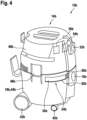
- FIG 4 shows a suction device 10b.
- the suction device 10b is formed by a vacuum cleaner.
- the suction device 10b has a housing unit 14b.
- the housing unit 14b consists of several housing parts 44b, 46b.
- the housing parts 44b, 46b are formed by separable housing shells.
- the housing unit 14b has a first housing part 44b and a second housing part 46b.
- the housing unit 14b further forms an intake opening 16b.
- the intake opening 16b is arranged on the first housing part 44b.
- the housing unit 14b forms a dirt opening 20b that is different from the suction opening 16b.
- the dirt opening 20b is formed in the first housing part 44b.
- the dirt opening 20b is arranged in one side of the first housing part 44b.
- the dirt opening 20b is formed by a rectangular recess in one side of the first housing part 44b.
- a cross-sectional area of the dirt opening 20b is significantly larger than a cross-sectional area of the suction opening 16b.
- the cross-sectional area of the dirt opening 20b is at least twice, preferably three times, larger than the cross-sectional area of the suction opening 16b.
- the dirt opening 20b is provided for filling the dust collection container 18b.
- the dirt opening 20b is provided for filling the dust collection container 18b during suction operation. Filling of the dirt opening 20b, which is different from the intake opening 16b, can take place independently of the intake opening 16b, whereby the intake opening 16b and the dirt opening 20b can be used simultaneously.
- the dirt opening 20b is at least partially coupled to the intake flow for sucking in ambient air, particularly contaminated air.
- the dirt opening 20b is coupled to the intake flow in at least one operating state.
- the suction device 10b has at least one closing unit 24b, which is provided for selectively opening and closing the dirt opening 20b.
- the closing unit 24b By means of the closing unit 24b, the dirt opening 20b can be made accessible or the dirt opening 20b can be closed.
- the closing unit 24b has two operating positions, namely an open position and a closed position.
- the closed position is in the Figure 4
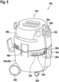
- the open position is shown in the Figure 6
- the closing unit 24b in a closed position, prevents dirt from entering the dirt opening 20b and also prevents a loss of suction power through the dirt opening 20b.
- the closing unit 24b in a closed state, dirt from the dust collection container 18b can be prevented from escaping to the outside.
- the closing unit 24b has a slide 34b guided on the housing unit 14b for selectively opening and closing the dirt opening 20b.
- the slide 34b of the closing unit 24b is guided directly on the housing unit 14b.
- the housing unit 14b has a guide rail (not further visible) in which the slide 34b is guided.
- the slide 34b of the closing unit 24b is arranged on a side wall of the first housing part 44b and is horizontally displaceable. In a closed position, the slide 34b of the closing unit 24b is intended to directly cover the dirt opening 20b from the inside.
- the slide 34b of the closing unit 24b is intended to be moved semi-automatically by an operator from a closed position to an open position.
- the closing unit 24b has an actuator (not further visible) which is provided for electrically opening and closing the slide 34b.
- the suction device 10b has an operating unit 54b.
- the operating unit 54b has at least one operating element 32b.
- the operating element 32b is provided for opening the closing unit 24b.
- the operating element 32b is formed, for example, by a push button.
- the operator actuates the operating element 32b and the slide 34b of the closing unit 24b thereby opens by means of the actuator of the closing unit 24b (not further visible) and either closes again after a defined time or as soon as the operating element 32b is released.
- the slide 34b is opened temporarily, in particular by an operator, in order to dispose of dirt via the dirt opening 20b during suction operation, for example using a hand shovel 58b.
- the slide 34b can then be closed again.
- the suction device 10b has a control and/or regulating unit 30b.
- the control and/or regulating unit 30b is provided for controlling and/or regulating the drive unit 12b.
- the suction device 10b has a sensor unit 26b for detecting a closed position of the closing unit 24b.
- the sensor unit 26b is connected to the control and/or regulating unit 30b.
- the sensor unit 26b has a contact sensor which, when the closing unit 24b is in a closed position, is contacted by the flap 36b of the closing unit 24b.
- the suction power of the drive unit 12b can be adjusted via the sensor unit 26b, for example by means of the control and/or regulating unit 30b.
- control and/or regulating unit 30b to temporarily increase the suction power of the drive unit 12b when the closing unit 24b is opened.
- control and/or regulating unit 30b is provided, in at least one operating state, to automatically open the closing unit 24b and to couple the dirt opening 20b to the suction flow.
- the control and/or regulating unit 30b is provided, when the operating element 32b is actuated by an operator, to automatically open the closing unit 24b and to couple the dirt opening 20b to the suction flow. By opening the closing unit 24b, dirt is sucked into the dust collection container 18b at the dirt opening 20b by means of the suction flow.
- the suction device 10b has an actuator 28b.
- the actuator 28b is provided to couple the at least one dirt opening 20b and/or the suction opening 16b to or decouple it from the suction flow, depending on a closed position of the closing unit 24b and depending on an actuation of the operating element 32b.
- the actuator 28b is provided to switch between the dirt opening 20b and the suction opening 16b.
- the actuator 28b is formed by a changeover switch.
- the actuator 28b is formed by a valve, in particular an electrically controlled 3/2-way valve.
- the actuator 28b is provided to couple the suction flow to the suction opening 16b instead of the dirt opening 20b when the closing unit 24b is closed.
- the actuator 28b is particularly provided for automatic switching between the suction opening 16b and the dirt opening 20b.
- the control element 32b When the control element 32b is actuated, the suction flow is coupled to the dirt opening 20b instead of the suction opening 16b.
- the actuator 28b it would also be conceivable for the actuator 28b to only partially redirect the suction flow, so that suction via the dirt opening 20b reduces the suction power at the suction opening 16b. merely reduced.
- the actuator 28b is automatically controlled by the control and/or regulating unit 30b upon actuation of the actuating element 32a.
- the actuator 28b it would also be conceivable for the actuator 28b to be formed by a mechanical switch, which mechanically switches the intake flow upon opening of the closing unit 24b ( Figure 7 ).
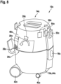
- FIG 8 shows a suction device 10c.
- the suction device 10c is formed by a vacuum cleaner.
- the suction device 10c has a housing unit 14c.
- the housing unit 14c consists of several housing parts 44c, 46c.
- the housing parts 44c, 46c are formed by separable housing shells.
- the housing unit 14c has a first housing part 44c and a second housing part 46c.
- the housing unit 14c further forms an intake opening 16c.
- the intake opening 16c is arranged on the first housing part 44c.
- the housing unit 14c forms a dirt opening 20c that is different from the suction opening 16c.
- the dirt opening 20c is formed in the first housing part 44c.
- the dirt opening 20c is arranged in one side of the first housing part 44c.
- the dirt opening 20c is formed by a rectangular recess in one side of the first housing part 44c.
- a cross-sectional area of the dirt opening 20c is significantly larger than a cross-sectional area of the suction opening 16c.
- the cross-sectional area of the dirt opening 20c is at least twice, preferably three times, larger than the cross-sectional area of the suction opening 16c.
- the dirt opening 20c is provided for filling the dust collection container 18c in the at least one operating state.
- the dirt opening 20c is provided for filling the dust collection container 18c during suction operation. Filling of the dirt opening 20c, which is different from the suction opening 16c, can take place independently of the suction opening 16c, whereby the suction opening 16c and the dirt opening 20c can be used simultaneously.
- the dirt opening 20c is designed to at least partially suck in ambient air, in particular contaminated air. coupled to the intake flow.
- the dirt opening 20c is coupled to the intake flow in at least one operating state.
- the flap 36c to close at least partially automatically.
- the flap 36c is temporarily opened, in particular by an operator, to dispose of dirt through the dirt opening 20c during vacuuming, for example, using a hand shovel 58c.
- the flap 36c can then be closed again.
- the suction device 10c has a control and/or regulating unit 30c.
- the control and/or regulating unit 30c is provided for controlling and/or regulating the drive unit 12c.
- the suction device 10c has a sensor unit 26c for detecting a closed position of the closing unit 24c.
- the sensor unit 26c is coupled to the control and/or regulating unit 30c.
- the sensor unit 26c has a contact sensor which, when the closing unit 24c is in a closed position, is contacted by the flap 36c of the closing unit 24c. Via the sensor unit 26c, a suction power of the drive unit 12c can be adjusted, for example by means of the control and/or regulating unit 30c. It would be conceivable, for example, for the control and/or regulating unit 30c to temporarily increase a suction power of the drive unit 12c when the closing unit 24c is opened.
- the suction device 10c has an actuator 28c.
- the actuator 28c is provided to couple the at least one dirt opening 20c to the intake flow or to decouple it from the intake flow depending on a closed position of the closing unit 24c.
- the actuator 28c is provided to open and/or close the intake opening 16c.
- the actuator 28c is formed by a closer.
- the actuator 28c is formed by a valve, in particular an electrically controlled valve.
- the actuator 28c is provided to close the intake opening 16c.
- the actuator 28c is particularly intended for automatically closing the suction opening 16c and exclusively suctioning through the dirt opening 20c.
- the actuator 28c to only partially close the suction opening 16c, so that suctioning through the dirt opening 20c reduces the suction power at the suction opening 16c.
- the actuator 28c is automatically controlled by the control and/or regulating unit 30c. If an opening of the closing unit 24c is detected by the sensor unit 26c, the actuator 28c is closed.
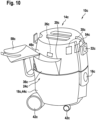
- the actuator 28c it would also be conceivable for the actuator 28c to be formed by a mechanical closer and to be only mechanically coupled to the closing unit 24c, wherein an opening of the closing unit 24c Closing of the intake opening 16c by means of the actuator 28b ( Figure 10 ).
- an intermediate collection container to be arranged on the flap 36c, in which the dirt is collected before being sucked into the dust collection container 18c with the intake flow.
- the intermediate collection container can, in particular, be fixedly arranged on an inner side of the flap 36c.
- the intermediate collection container can be at least partially folded out of the housing unit 14c with the flap 36c.
- FIG 11 shows a suction device 10d.
- the suction device 10d is formed by a vacuum cleaner.
- the suction device 10d has a housing unit 14d.
- the housing unit 14d consists of several housing parts 44d, 46d.
- the housing parts 44d, 46d are formed by separable housing shells.
- the housing unit 14d has a first housing part 44d and a second housing part 46d.
- the housing unit 14d further forms an intake opening 16d.
- the intake opening 16d is arranged on the first housing part 44d.
- the housing unit 14d forms a dirt opening 20d, which is different from the suction opening 16d.
- the dirt opening 20d is formed in the first housing part 44d.
- the dirt opening 20d is arranged in one side of the first housing part 44d.
- the dirt opening 20d is formed by a rectangular recess in one side of the first housing part 44d.
- the dirt opening 20d connects an environment to the dust collection container 18d via the dirt opening 20d.
- the dirt opening 20d is connected to the dust collection container 18d via a separate suction channel 56d.
- the suction channel 56d is arranged, for example, in the second housing part 46d.
- the housing unit 14d forms the suction channel 56d.
- a cross-sectional area of the dirt opening 20d is significantly larger than a cross-sectional area of the suction opening 16d.
- the cross-sectional area of the dirt opening 20d is at least 2 times, preferably 3 times, larger than the cross-sectional area of the intake opening 16d.
- the dirt opening 20d is in the at least one operating state is provided for filling the dust collection container 18d.
- the dirt opening 20d is provided for filling the dust collection container 18d in the suction mode. Filling of the dirt opening 20d, which is different from the suction opening 16d, can take place independently of the suction opening 16d, wherein the suction opening 16d and the dirt opening 20d can be used simultaneously.
- the dirt opening 20d is at least partially coupled to the suction flow for sucking in ambient air, in particular contaminated air.
- the dirt opening 20d is coupled to the suction flow in at least one operating state.
- the suction device 10d has at least one closing unit 24d, which is provided for selectively opening and closing the dirt opening 20d.
- the closing unit 24d By means of the closing unit 24d, the dirt opening 20d can be made accessible or the dirt opening 20d can be closed.
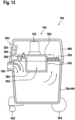
- the closing unit 24d has two operating positions, namely an open position and a closed position. The closed position is in the Figure 11 The open position is shown in the Figure 12 shown. In a closed position, the closing unit 24d prevents dirt from entering the dirt opening 20d and prevents a loss of suction power through the dirt opening 20d. In a closed state, the closing unit 24d can prevent dirt from escaping from the dust collection container 18d.
- the closing unit 24d has a drawer 38d guided in the housing unit 14d for selectively opening and closing the dirt opening 20d.
- the drawer 38d of the closing unit 24d is guided in a manner not further visible via pull-out rails on the housing unit 14d.
- the drawer 38d of the closing unit 24d is arranged on a side wall of the first housing part 44d and is partially retractable. In a closed position, the drawer 38d of the closing unit 24d is intended to fill the dirt opening 20d.
- the drawer 38d of the closing unit 24d is intended to be manually moved by an operator from a closed position to an open position. For this purpose, the drawer 38d is pulled out of the first housing part 44d. Closing the drawer 38d of the closing unit 24d takes place also manually. However, it would also be conceivable that the closing of drawer 38d could be at least partially automated.
- the suction device 10d has a control and/or regulating unit 30d.
- the control and/or regulating unit 30d is provided for controlling and/or regulating the drive unit 12d.
- the suction device 10d has a sensor unit 26d for detecting a closed position of the closing unit 24d.
- the sensor unit 26d is coupled to the control and/or regulating unit 30d.
- the sensor unit 26d has a contact sensor, which is contacted by the drawer 38d of the closing unit 24d when the closing unit 24d is in a closed position.
- the suction channel 56d extends exactly between the receiving area 40d of the drawer 38d and the dust collection container 18d.
- the actuator 28d is provided to temporarily open the suction channel 56d after closing the closing unit 24d in order to vacuum the receiving area 40d ( Figure 13 ).
- the drawer 38d is temporarily opened, in particular by an operator, in order to dispose of dirt via the dirt opening 20d during vacuuming operation, for example, using a hand shovel 58d.
- the receiving area 40d of the drawer 38d is filled with dirt.
- the drawer 38d can then be closed again, with the receiving area 40d being vacuumed into the dust collection container 18d by means of the suction flow while the drawer 38d is closed.
Landscapes
- Engineering & Computer Science (AREA)
- Mechanical Engineering (AREA)
- Nozzles For Electric Vacuum Cleaners (AREA)
Description
- Es sind bereits Saugvorrichtungen, insbesondere Staubsauger, mit zumindest einer Antriebseinheit zu einer Erzeugung eines Ansaugstroms, mit zumindest einer Gehäuseeinheit, welche zumindest eine Ansaugöffnung ausbildet, die in zumindest einem Betriebszustand der Antriebseinheit zu einem Ansaugen einer, insbesondere verschmutzten, Umgebungsluft mittels des Ansaugstroms vorgesehen ist, und mit zumindest einem in der Gehäuseeinheit angeordneten Staubauffangbehälter zu einer Aufnahme von von dem Ansaugstrom abgeschiedenem Schmutz, vorgeschlagen worden. Siehe dazu z. B. das Dokument
US2019270585A1 . - Die Erfindung geht aus von einer Saugvorrichtung, insbesondere von einem Staubsauger, mit zumindest einer Antriebseinheit zu einer Erzeugung eines Ansaugstroms, mit zumindest einer Gehäuseeinheit, welche zumindest eine Ansaugöffnung ausbildet, die in zumindest einem Betriebszustand der Antriebseinheit zu einem Ansaugen einer, insbesondere verschmutzten, Umgebungsluft mittels des Ansaugstroms vorgesehen ist, und mit zumindest einem in der Gehäuseeinheit angeordneten Staubauffangbehälter zu einer Aufnahme von von dem Ansaugstrom abgeschiedenem Schmutz.
- Es wird vorgeschlagen, dass die Gehäuseeinheit zumindest eine von der Ansaugöffnung verschiedene Schmutzöffnung ausbildet, welche in dem zumindest einen Betriebszustand zu einer Befüllung des Staubauffangbehälters vorgesehen ist. Vorzugsweise kann eine Befüllung der von der Ansaugöffnung verschiedenen Schmutzöffnung unabhängig von der Ansaugöffnung erfolgen, wobei insbesondere die Ansaugöffnung und die Schmutzöffnung gleichzeitig genutzt werden können. Bevorzugt können die Ansaugöffnung und die Schmutzöffnung, insbesondere von verschiedenen Personen, gleichzeitig zu verschiedenen Zwecken genutzt werden.
- Durch die erfindungsgemäße Ausgestaltung der Saugvorrichtung kann insbesondere eine vorteilhaft flexibel einsetzbare Saugvorrichtung bereitgestellt werden. Die Saugvorrichtung kann insbesondere von mehreren Personen gleichzeitig genutzt werden. Es kann insbesondere neben der normalen Absaugung über die Ansaugöffnung eine zusätzliche Befüllung des Staubauffangbehälters erreicht werden. Bei der Reinigung von Staub, beispielsweise nach der Arbeit mit einem Elektrowerkzeug zur Holzbearbeitung in einer Werkstatt oder bei einem Kunden, werden größere Flächen häufig mit einer Saugvorrichtung, insbesondere mit einem Staubsauger, besonders bevorzugt einem Industriesauger, gereinigt, Feinheiten und verwinkelte Ecken müssen jedoch häufig beispielsweise mit einem Handbesen und einer Handschaufel gereinigt werden. Für die Entsorgung des Abfalls auf der Handschaufel kann insbesondere die Schmutzöffnung genutzt werden. Oftmals räumen zudem nach erledigter Arbeit mehrere Personen gleichzeitig auf, eine Person mit der Saugvorrichtung und eine beispielsweise mit einer Schaufel und einem Besen, wobei die Schaufel jeweils über die Schmutzöffnung geleert werden kann.
- Unter einer "Saugvorrichtung" soll in diesem Zusammenhang insbesondere eine Vorrichtung verstanden werden, mittels der ein Luft-Schmutz-Gemisch, insbesondere mittels eines Unterdrucks, abgesaugt wird, wobei der Schmutz insbesondere innerhalb der Saugvorrichtung abgeschieden, insbesondere über eine Filtereinheit ausgefiltert, wird. Vorzugsweise wird über die Vorrichtung verschmutzte Luft angesaugt, gefiltert und wieder ausgeblasen. Die Antriebseinheit der Saugvorrichtung ist zu einer Erzeugung eines Ansaugstroms vorgesehen. Insbesondere ist die Antriebseinheit zu einer Erzeugung eines für eine Absaugung benötigten Unterdrucks vorgesehen. Es sind verschiedene, einem Fachmann als sinnvoll erscheinende Ausgestaltungen der Antriebseinheit denkbar. Die Antriebseinheit kann beispielsweise als eine Turbine ausgebildet sein.
- Die Gehäuseeinheit ist insbesondere fahrbar ausgebildet. Insbesondere weist die Saugvorrichtung an der Gehäuseeinheit angeordnete Räder auf, welche zu einem einfachen Verschieben der Gehäuseeinheit vorgesehen sind. Die Gehäuseeinheit ist insbesondere zu einer Aufnahme und/oder zu einem Schutz von wesentlichen Bauteilen der Saugvorrichtung, wie insbesondere der Antriebseinheit und/oder des Staubauffangbehälters, vorgesehen. Vorzugsweise kann die Gehäuseeinheit insbesondere aus mehreren Gehäuseteilen bestehen. Die Gehäuseteile sind insbesondere von voneinander trennbaren Gehäuseschalen gebildet. Bevorzugt weist die Gehäuseeinheit zumindest ein den Staubauffangbehälter aufnehmendes erstes Gehäuseteil auf. Vorzugsweise bildet das erste Gehäuseteil den Staubauffangbehälter aus. Das erste Gehäuseteil ist insbesondere einstückig mit dem Staubauffangbehälter ausgebildet. Es wäre jedoch auch denkbar, dass ein separater Staubauffangbehälter in dem Gehäuseteil angeordnet ist. Unter "einstückig" soll insbesondere stoffschlüssig verbunden, wie beispielsweise durch einen Schweißprozess und/oder Klebeprozess usw., und besonders vorteilhaft angeformt verstanden werden, wie durch die Herstellung aus einem Guss und/oder durch die Herstellung in einem Ein- oder Mehrkomponentenspritzverfahren. Bevorzugt weist die Gehäuseeinheit zumindest ein die Antriebseinheit aufnehmendes zweites Gehäuseteil auf. Das zweite Gehäuseteil ist insbesondere zu einer lösbaren Befestigung auf dem ersten Gehäuseteil vorgesehen. Ferner ist die Ansaugöffnung insbesondere von einem Schlauchanschluss gebildet. Vorzugsweise ist die Ansaugöffnung insbesondere von einem Schlauchanschlussstutzen zu einer Kopplung mit einem Saugschlauch gebildet. Grundsätzlich wäre auch denkbar, dass die Ansaugöffnung fest mit einem Saugschlauch verbunden ist. Des Weiteren soll unter einem "Staubauffangbehälter" in diesem Zusammenhang insbesondere ein Behälter verstanden werden, der zu einer Aufnahme eines, insbesondere durch einen Filter einer Filtereinheit, aus einer abgesaugten Luft abgeschiedenen Schmutzes vorgesehen ist. Vorzugsweise soll darunter ein Behälter verstanden werden, der in einem Betrieb dazu vorgesehen ist, Staub zu einer anschließenden Entnahme aus der Saugvorrichtung und bevorzugt einer anschließenden Entsorgung aufzunehmen. Eine Aufnahme kann dabei sowohl direkt, als auch indirekt, wie beispielsweise über einen in den Staubauffangbehälter eingelegten Beutel, erfolgen. Vorzugsweise erfolgt eine Aufnahme jedoch direkt, insbesondere beutellos. Bevorzugt ist der Staubauffangbehälter zumindest teilweise, insbesondere über die Gehäuseeinheit, zumindest von der Antriebseinheit trennbar ausgebildet. Dadurch kann vorzugsweise ein leichtes Entleeren ermöglicht werden. Vorzugsweise ist der Staubauffangbehälter in die Gehäuseeinheit integriert. Darunter, dass der Staubauffangbehälter "in die Gehäuseeinheit integriert ist", soll in diesem Zusammenhang insbesondere verstanden werden, dass der Staubauffangbehälter in zumindest einem Zustand zumindest teilweise durch die Gehäuseeinheit eingefasst ist und/oder zumindest teilweise von der Gehäuseeinheit ausgebildet wird. Vorzugsweise bildet der Staubauffangbehälter zumindest einen Teil einer Außenhaut der Gehäuseeinheit, insbesondere der Saugvorrichtung.
- Unter einer "Schmutzöffnung" soll in diesem Zusammenhang insbesondere eine von der Ansaugöffnung verschiedene Öffnung verstanden werden, welche in zumindest einem Betriebszustand mit dem Staubauffangbehälter gekoppelt ist. Vorzugsweise kann über die Schmutzöffnung der Staubauffangbehälter in dem zumindest einen Betriebszustand gefüllt werden, wobei eine Befüllung direkt, insbesondere indem Schmutz direkt in den Staubauffangbehälter geschüttet werden kann, als auch indirekt erfolgen kann, insbesondere indem Schmutz von der Schmutzöffnung in den Staubauffangbehälter gesaugt und/oder indem Schmutz über einen Zwischenauffangbehälter, wie insbesondere einer Klappe und/oder einer Schublade, in den Staubauffangbehälter befördert wird. Bevorzugt ist die Schmutzöffnung insbesondere zu einer direkten Befüllung mit Schmutz vorgesehen, insbesondere frei von einem zusätzlichen Saugschlauch. Vorzugsweise ist die Schmutzöffnung frei von einem Anschlussstutzen für einen Saugschlauch. Vorzugsweise dient die Schmutzöffnung insbesondere dazu, dass ein Bediener frei von einer Nutzung der Ansaugöffnung Abfälle und/oder Staub in den Staubauffangbehälter leeren kann. Unter "vorgesehen" soll insbesondere speziell ausgelegt und/oder ausgestattet verstanden werden. Darunter, dass ein Objekt zu einer bestimmten Funktion vorgesehen ist, soll insbesondere verstanden werden, dass das Objekt diese bestimmte Funktion in zumindest einem Anwendungs- und/oder Betriebszustand erfüllt und/oder ausführt.
- Ferner wird vorgeschlagen, dass die zumindest eine Schmutzöffnung zu einem Ansaugen einer, insbesondere verschmutzten, Umgebungsluft zumindest teilweise mit dem Ansaugstrom gekoppelt ist. Vorzugsweise erfolgt an der Schmutzöffnung in zumindest einem Betriebszustand eine aktive Absaugung an der Schmutzöffnung. Vorzugsweise ist die Schmutzöffnung in zumindest einem Betriebszustand mit dem Ansaugstrom gekoppelt. Bevorzugt ist die Saugvorrichtung in zumindest einem Betriebszustand dazu vorgesehen, in einer Umgebung der Schmutzöffnung Schmutz mittels des Ansaugstroms anzusaugen. Beispielsweise wäre denkbar, dass der Ansaugstrom von einem Bediener, beispielsweise mittels eines Schalters, mit der Schmutzöffnung koppelbar ist und/oder dass eine Kopplung selbsttätig erfolgt, wie beispielsweise bei einem Öffnen oder Schließen der Schmutzöffnung. Dadurch kann insbesondere eine vorteilhaft flexibel einsetzbare Saugvorrichtung bereitgestellt werden. Es kann insbesondere neben der normalen Absaugung über die Ansaugöffnung eine zusätzliche Absaugung erreicht werden. Für die Entsorgung von Schmutz, wie beispielsweise von einer Handschaufel, kann insbesondere die Schmutzöffnung genutzt werden. Es kann insbesondere zuverlässig ein Verschütten vermieden werden. Es kann insbesondere ein Leersaugen der Schaufel erreicht werden.
- Neben einer aktiven Absaugung an der Schmutzöffnung wäre jedoch auch denkbar, dass der Schmutz direkt oder über einen Zwischenaufnahmebereich frei von einer aktiven Absaugung in den Staubauffangbehälter gebracht werden kann.
- Des Weiteren wird vorgeschlagen, dass eine Querschnittsfläche der Schmutzöffnung wesentlich größer ist als eine Querschnittsfläche der Ansaugöffnung. Vorzugsweise ist eine Querschnittsfläche der Schmutzöffnung insbesondere zumindest 2-mal, vorzugsweise zumindest 3-mal und besonders bevorzugt zumindest 5-mal größer als eine Querschnittsfläche der Ansaugöffnung. Vorzugsweise weist die Ansaugöffnung eine Querschnittsfläche von maximal 80 cm2, vorzugsweise von maximal 65 cm2 und besonders bevorzugt von maximal 50 cm2 auf. Bevorzugt weist die Schmutzöffnung eine Querschnittsfläche von zumindest 100 cm2, vorzugsweise von zumindest 130 cm2 und besonders bevorzugt von zumindest 160 cm2 auf. Die Querschnittsfläche der Schmutzöffnung wird insbesondere direkt von der Gehäuseeinheit begrenzt. Vorzugsweise ist die Querschnittsfläche der Schmutzöffnung insbesondere zumindest annähernd rechteckig. Die Querschnittsfläche der Ansaugöffnung wird insbesondere direkt von der Gehäuseeinheit begrenzt. Bevorzugt ist die Querschnittsfläche der Ansaugöffnung zumindest annähernd kreisförmig. Dadurch kann insbesondere eine vorteilhaft flexibel einsetzbare Saugvorrichtung bereitgestellt werden. Es kann insbesondere neben der normalen Absaugung über die Ansaugöffnung eine zusätzliche Absaugung, insbesondere von größerem Schmutz, erreicht werden. Bei der Arbeit mit Elektrowerkzeugen können neben Staub auch kleine Reste vom Werkstück anfallen. Diese können schnell zu groß für die Ansaugöffnung der Saugvorrichtung oder am Saugzubehör sein und müssten damit mit dem Handbesen und der Handschaufel zusammengefegt werden. Entsprechende Reste können insbesondere über die Schmutzöffnung in den Staubauffangbehälter abgesaugt werden.
- Es wird ferner vorgeschlagen, dass die Saugvorrichtung zumindest eine Filtereinheit aufweist, welche entlang des Ansaugstroms strömungstechnisch hinter der Ansaugöffnung und hinter der Schmutzöffnung angeordnet ist und dazu vorgesehen ist, Schmutz von dem Ansaugstrom abzuscheiden. Vorzugsweise ist die Filtereinheit strömungstechnisch vor der Antriebseinheit und hinter dem Staubauffangbehälter angeordnet. Vorzugsweise weist die Filtereinheit zumindest einen Filter auf, welcher in einem Betrieb zu einer Filterung abgesaugter Luft vorgesehen ist. Bei einem Vorsehen eines Beutels in dem Staubauffangbehälter wäre auch denkbar, dass der Filter als ein Filtersack ausgebildet ist, welcher gleichzeitig als ein Staubbeutel dient. Unter einer "Filtereinheit" soll in diesem Zusammenhang insbesondere eine Einheit verstanden werden, welche in einem Betrieb zu einer Filterung abgesaugter Luft vorgesehen ist. Hierzu weist die Filtereinheit vorzugsweise einen Filter auf, durch welchen die Luft durchgesaugt wird. Dabei sind verschiedene, einem Fachmann als sinnvoll erscheinende Filter denkbar. Vorzugsweise ist der Filter als Lamellenfilter, insbesondere als rechteckiger Lamellenfilter, ausgebildet. Dadurch kann insbesondere eine vorteilhafte Saugvorrichtung bereitgestellt werden. Es kann insbesondere erreicht werden, dass sowohl ein Ansaugstrom der Ansaugöffnung als auch der Schmutzöffnung gefiltert wird.
- Es wird weiter vorgeschlagen, dass die Saugvorrichtung zumindest eine Schließeinheit aufweist, welche zu einem wahlweisen Öffnen und Schließen der Schmutzöffnung vorgesehen ist. Vorzugsweise kann mittels der Schließeinheit die Schmutzöffnung zugänglich gemacht werden und/oder die Schmutzöffnung geschlossen werden. Vorzugsweise weist die Schließeinheit zumindest zwei Betriebsstellungen auf, insbesondere eine offene Stellung und eine geschlossene Stellung. Vorzugsweise verhindert die Schließeinheit in einer geschlossenen Stellung, dass Schmutz durch die Schmutzöffnung gelangt. Bevorzugt kann mittels der Schließeinheit in einem geschlossenen Zustand auch verhindert werden, dass Schmutz aus dem Staubauffangbehälter nach außen gelangt. Unter einer "Schließeinheit" soll in diesem Zusammenhang insbesondere eine Einheit verstanden werden, welche zu einem optionalen Verschließen der Schmutzöffnung vorgesehen ist. Vorzugsweise ist die Einheit in einer geschlossenen Stellung dazu vorgesehen, die Schmutzöffnung von innen oder außen zu verdecken und/oder die Schmutzöffnung materiell auszufüllen. Das Öffnen der Schließeinheit kann insbesondere entweder manuell, teilautomatisiert oder automatisch erfolgen. Bevorzugt ist die Schließeinheit dazu vorgesehen, manuell von einer geschlossenen Stellung in eine offene Stellung gebracht zu werden. Insbesondere ist die Schließeinheit auch dazu vorgesehen, manuell von einer offenen Stellung in eine geschlossene Stellung gebracht zu werden. Es wäre jedoch auch denkbar, dass ein Öffnen und/oder eine Schließung der Schließeinheit selbsttätig erfolgt. Es sind verschiedene, einem Fachmann als sinnvoll erscheinende Ausgestaltungen der Schließeinheit denkbar, beispielsweise wäre denkbar, dass die Schließeinheit zumindest einen Schieber, zumindest eine Klappe und/oder zumindest eine Schublade aufweist. Dadurch kann insbesondere vorteilhaft die Schmutzöffnung verschlossen werden. Es kann insbesondere ein ungewollter Austritt von Schmutz aus der Schmutzöffnung vermieden werden. Ferner kann zudem ein dauerhafter Verlust von Saugleistung an der Schmutzöffnung vermieden werden.
- Damit beim Einfüllen wenig Schmutz daneben geht und um zu gewährleisten, dass der Schmutz leichter eingefüllt werden kann und um den Bauraum der Schließeinheit möglichst klein zu halten, wäre denkbar, dass die Schließeinheit faltbar ausgebildet ist. Beispielsweise wäre denkbar, dass sich die Klappe und/oder Schublade der Schließeinheit beim Öffnen auffaltet, hierdurch die Fläche vergrößert und hierbei ihre Form verändert. Bei einer Schublade wäre beispielsweise denkbar, dass die Schublade teleskopartig ausgebildet ist oder die Form eines schüsselartig gebogenen Fächers aufweist. Bei einer Klappe wäre beispielsweise denkbar, dass die Klappe in Form eines Trichters ausgebildet ist.
- Ferner wird vorgeschlagen, dass die Saugvorrichtung zumindest eine Sensoreinheit zu einer Erfassung einer Schließstellung der zumindest einen Schließeinheit aufweist. Vorzugsweise weist die Sensoreinheit zumindest einen Kontaktsensor auf, welcher in einer Schließstellung der zumindest einen Schließeinheit, insbesondere von der Schließeinheit, kontaktiert wird. Unter einer "Sensoreinheit" soll in diesem Zusammenhang insbesondere eine Einheit verstanden werden, die zumindest einen Sensor aufweist, welcher dazu vorgesehen ist, zumindest eine Kenngröße und/oder eine physikalische Eigenschaft aufzunehmen, wobei die Aufnahme aktiv, wie insbesondere durch Erzeugen und Aussenden eines elektrischen Messsignals, und/oder passiv, wie insbesondere durch eine Erfassung von Eigenschaftsänderungen eines Sensorbauteils, stattfinden kann. Es sind verschiedene, dem Fachmann als sinnvoll erscheinende Sensoreinheiten denkbar. Dadurch kann insbesondere eine Stellung der Schließeinheit überwacht werden. Es kann insbesondere erfasst werden, wenn die Schließeinheit von einem Bediener geöffnet wird. Hierdurch kann insbesondere eine bedarfsgerechte Absaugung an der Schmutzöffnung bereitgestellt werden.
- Des Weiteren wird vorgeschlagen, dass die Saugvorrichtung zumindest ein Stellglied aufweist, das dazu vorgesehen ist, abhängig von einer Schließstellung der zumindest einen Schließeinheit die zumindest eine Schmutzöffnung und/oder die zumindest eine Ansaugöffnung mit dem Ansaugstrom zu koppeln oder von diesem zu entkoppeln. Vorzugsweise ist zwischen der Schmutzöffnung und dem Staubauffangbehälter ein separater Absaugkanal vorgesehen, wobei das Stellglied insbesondere zu einem Öffnen und/oder Verschließen des Absaugkanals und/oder der Ansaugöffnung vorgesehen ist. Das Stellglied kann mechanisch, mechatronisch oder elektrisch ausgebildet sein. Es wäre denkbar, dass das Stellglied mechanisch mit der Schließeinheit gekoppelt ist, und abhängig von einer Schließstellung automatisch betätigt wird. Das Stellglied ist insbesondere von einem Schließer oder Umschalter gebildet. Das Stellglied ist insbesondere von einem mechatronischen Bauteil gebildet, das dazu vorgesehen ist, elektrische Signale in eine Bewegung, insbesondere in eine Dreh-, Schwenk- und/oder Linearbewegung, umzusetzen. Bevorzugt ist das Stellglied von einem Ventil gebildet. Vorzugsweise ist das Stellglied in einem geschlossenen Zustand der Schließeinheit dazu vorgesehen, den Absaugkanal zu verschließen. Alternativ oder zusätzlich wäre jedoch auch denkbar, dass das Stellglied dazu vorgesehen ist, den Absaugkanal zumindest temporär nach einem Schließen der Schließeinheit geöffnet zu halten oder zu öffnen. Dadurch kann insbesondere ein Ansaugstrom an der Schmutzöffnung beeinflusst werden. Es kann insbesondere erfasst werden, wenn die Schließeinheit von einem Bediener geöffnet wird. Hierdurch kann insbesondere eine bedarfsgerechte Absaugung an der Schmutzöffnung bereitgestellt werden. Ferner kann insbesondere vermieden werden, dass bei einem Öffnen der Schließeinheit durch den Druckabfall Schmutz aus dem Staubauffangbehälter über die Schmutzöffnung austritt.
- Es wird ferner vorgeschlagen, dass die Saugvorrichtung zumindest eine Steuer- und/oder Regeleinheit aufweist, die in zumindest einem Betriebszustand, insbesondere bei einer Betätigung eines Bedienelements durch einen Bediener, dazu vorgesehen ist, die Schließeinheit selbsttätig zu öffnen und die zumindest eine Schmutzöffnung mit dem Ansaugstrom zu koppeln. Vorzugsweise weist die Saugvorrichtung zumindest eine Bedieneinheit mit dem zumindest einen Bedienelement auf. Die Bedieneinheit dient insbesondere zu einer Steuerung der Saugvorrichtung. Vorzugsweise kann die Steuer- und/oder Regeleinheit zudem zu einer Steuerung des Stellglieds vorgesehen sein. Die Steuer- und/oder Regeleinheit ist insbesondere dazu vorgesehen, in zumindest einem Betriebszustand, insbesondere bei einer Betätigung eines Bedienelements durch einen Bediener, die Schließeinheit selbsttätig zu öffnen und die zumindest eine Schmutzöffnung über das Stellglied mit dem Ansaugstrom zu koppeln. Die Schließeinheit kann insbesondere teilautomatisiert öffnen. Beispielsweise ist denkbar, dass der Bediener das Bedienelement betätigt, wie beispielsweise mit dem Fuß einen Fußtaster, und die Schließeinheit dadurch mittels eines Aktors öffnet und entweder nach einer definierten Zeit wieder schließt oder sobald das Bedienelement losgelassen wird. Es wäre auch denkbar, dass der Bediener beispielsweise mit dem Fuß eine Kickbewegung zu einem Öffnen der Schließeinheit durchführt, wie dies beispielsweise beim Auto zum automatischen Kofferraumöffnen bekannt ist. Unter einer "Steuer- und/oder Regeleinheit" soll insbesondere eine Einheit mit zumindest einer Steuerelektronik verstanden werden. Unter einer "Steuerelektronik" soll insbesondere eine Einheit mit einer Prozessoreinheit und mit einer Speichereinheit sowie mit einem in der Speichereinheit gespeicherten Betriebsprogramm verstanden werden. Unter einer "Bedieneinheit" soll hier insbesondere eine Einheit verstanden werden, die zumindest ein Bauteil, insbesondere ein Bedienelement, aufweist, das direkt von einem Bediener betätigbar ist und die dazu vorgesehen ist, durch eine Betätigung und/oder durch eine Eingabe von Parametern einen Prozess und/oder einen Zustand einer mit der Bedieneinheit gekoppelten Einheit zu beeinflussen und/oder zu ändern. Unter einem "Bedienelement" soll insbesondere ein Element der Bedieneinheit verstanden werden, das dazu vorgesehen ist, bei einem Bedienvorgang eine Eingabegröße von einem Bediener aufzunehmen und insbesondere unmittelbar von einem Bediener kontaktiert zu werden, wobei ein Berühren des Bedienelements sensiert und/oder eine auf das Bedienelement ausgeübte Betätigungskraft sensiert und/oder mechanisch zur Betätigung einer Einheit weitergeleitet wird. Dadurch kann insbesondere erreicht werden, dass die Schließeinheit nicht manuell von einem Bediener geöffnet werden muss. Es kann insbesondere ein vorteilhaft hoher Bedienkomfort bereitgestellt werden.
- Alternativ oder zusätzlich wäre auch denkbar, dass die Schließeinheit vollautomatisch öffnet. So wäre insbesondere denkbar, dass sobald die Saugvorrichtung eine Annäherung an die Schließeinheit mittels einer Sensoreinheit erfasst, die Schließeinheit automatisch geöffnet wird und entweder nach einer definierten Zeit oder sobald eine Entfernung von der Schließeinheit bemerkt wird, die Schließeinheit wieder verschlossen wird. Das Öffnen der Schließeinheit kann entweder durch einen elektrischen Aktor oder durch den von der Antriebseinheit erzeugten Unterdruck erfolgen. Es wäre beispielsweise denkbar, dass durch den Unterdruck ein, insbesondere federbeaufschlagter, Kolben angezogen wird, der die Schließeinheit öffnet und schließt. Zum Schließen muss der Unterdruck analog zur Filterreinigung in seiner Richtung umgeschaltet werden, sodass die Schließeinheit vom Unterdruck angezogen wird und somit nach innen öffnet.
- Es wird weiter vorgeschlagen, dass die zumindest eine Schließeinheit zumindest einen an der Gehäuseeinheit geführten Schieber zu einem wahlweisen Öffnen und Schließen der Schmutzöffnung aufweist. Vorzugsweise ist der Schieber direkt an der Gehäuseeinheit geführt. Bevorzugt weist die Gehäuseeinheit insbesondere zumindest eine Führungsschiene auf, in welcher der Schieber geführt ist. Vorzugsweise ist der Schieber in einer geschlossenen Stellung der Schließeinheit dazu vorgesehen, die Schmutzöffnung von innen und/oder außen zu verdecken. Der Schieber ist insbesondere an einer Seitenwand der Gehäuseeinheit angeordnet. Dadurch kann insbesondere eine besonders vorteilhafte Schließeinheit bereitgestellt werden.
- Ferner wird vorgeschlagen, dass die zumindest eine Schließeinheit zumindest eine an der Gehäuseeinheit schwenkbar gelagerte Klappe zu einem wahlweisen Öffnen und Schließen der Schmutzöffnung aufweist. Vorzugsweise ist die Klappe über ein Drehgelenk schwenkbar an der Gehäuseeinheit gelagert. Vorzugsweise ist die Klappe in einer geschlossenen Stellung der Schließeinheit dazu vorgesehen, die Schmutzöffnung von außen zu verdecken. Die Klappe ist insbesondere an einer Seitenwand oder auf einer Oberseite der Gehäuseeinheit angeordnet. Es wäre insbesondere denkbar, dass an der Klappe zudem ein Zwischenauffangbehälter angeordnet ist, in welchem der Schmutz aufgenommen wird, bevor er mit dem Ansaugstrom in dem Staubauffangbehälter angesaugt wird. Der Zwischenauffangbehälter kann insbesondere fest auf einer Innenseite der Klappe angeordnet sein. Insbesondere kann der Zwischenauffangbehälter mit der Klappe zumindest teilweise aus der Gehäuseeinheit herausgeklappt werden. Dadurch kann insbesondere eine besonders vorteilhafte Schließeinheit bereitgestellt werden.
- Des Weiteren wird vorgeschlagen, dass die zumindest eine Schließeinheit zumindest eine in der Gehäuseeinheit geführte Schublade zu einem wahlweisen Öffnen und Schließen der Schmutzöffnung aufweist. Vorzugsweise weist die Schublade zumindest eine Schubladenfront auf und begrenzt insbesondere einen Aufnahmebereich. Die Schublade weist den Aufnahmebereich auf. Bevorzugt ist die Schublade insbesondere über zumindest eine Auszugsschiene an dem Gehäuse geführt. Vorzugsweise ist die Schubladenfront der Schublade in einer geschlossenen Stellung der Schließeinheit dazu vorgesehen, die Schmutzöffnung auszufüllen und/oder die Schmutzöffnung von außen zu verdecken. Die Schublade ist insbesondere in einer Seitenwand der Gehäuseeinheit geführt. Der von der Schublade begrenzte Aufnahmebereich ist insbesondere dazu vorgesehen, Schmutz temporär aufzunehmen, bevor er mit dem Ansaugstrom in dem Staubauffangbehälter angesaugt wird. Vorzugsweise kann ein Bediener Schmutz direkt in den von der Schublade begrenzten Aufnahmebereich schütten. Der Aufnahmebereich der Schublade ist insbesondere über die Schublade zumindest teilweise aus der Gehäuseeinheit herausziehbar. Dadurch kann insbesondere eine besonders vorteilhafte Schließeinheit bereitgestellt werden.
- Es wird ferner vorgeschlagen, dass die Saugvorrichtung zumindest ein Stellglied aufweist, das dazu vorgesehen ist, in einem geschlossenen Zustand der Schließeinheit den Ansaugstrom mit einem Aufnahmebereich der Schublade zu koppeln. Vorzugsweise ist zwischen dem Aufnahmebereich der Schublade und dem Staubauffangbehälter ein separater Absaugkanal vorgesehen, wobei das Stellglied insbesondere zu einem Öffnen und/oder Verschließen des Absaugkanals vorgesehen ist. Bevorzugt ist das Stellglied von einem Ventil, insbesondere von einem elektrisch angesteuerten Ventil, gebildet. Vorzugsweise ist das Stellglied dazu vorgesehen, den Absaugkanal zumindest temporär nach einem Schließen der Schließeinheit geöffnet zu halten oder zu öffnen. Dadurch kann insbesondere ein nachträgliches Aussaugen des Aufnahmebereichs der Schublade erreicht werden. Hierdurch kann insbesondere eine bedarfsgerechte Absaugung an der Schmutzöffnung bereitgestellt werden. Ferner kann insbesondere vermieden werden, dass bei einem Öffnen der Schließeinheit durch den Druckabfall Schmutz aus dem Staubauffangbehälter über die Schmutzöffnung austritt. Es kann insbesondere ein Verlust an Saugleistung an der Ansaugöffnung bei einem Befüllen der Schublade vermieden werden.
- Die erfindungsgemäße Saugvorrichtung soll hierbei nicht auf die oben beschriebene Anwendung und Ausführungsform beschränkt sein. Insbesondere kann die erfindungsgemäße Saugvorrichtung zu einer Erfüllung einer hierin beschriebenen Funktionsweise eine von einer hierin genannten Anzahl von einzelnen Elementen, Bauteilen und Einheiten abweichende Anzahl aufweisen. Zudem sollen bei den in dieser Offenbarung angegebenen Wertebereichen auch innerhalb der genannten Grenzen liegende Werte als offenbart und als beliebig einsetzbar gelten.
- Weitere Vorteile ergeben sich aus der folgenden Zeichnungsbeschreibung. In der Zeichnung sind vier Ausführungsbeispiele der Erfindung dargestellt. Die Zeichnung, die Beschreibung und die Ansprüche enthalten zahlreiche Merkmale in Kombination. Der Fachmann wird die Merkmale zweckmäßigerweise auch einzeln betrachten und zu sinnvollen weiteren Kombinationen zusammenfassen.
- Es zeigen:
- Fig. 1
- eine erfindungsgemäße Saugvorrichtung mit einer Gehäuseeinheit, welche eine Ansaugöffnung ausbildet, und mit einer Schließeinheit in einer geschlossenen Stellung in einer schematischen Darstellung,
- Fig. 2
- die erfindungsgemäße Saugvorrichtung mit der Gehäuseeinheit, welche die Ansaugöffnung ausbildet, und mit der Schließeinheit in einer offenen Stellung in einer schematischen Darstellung,
- Fig. 3
- die erfindungsgemäße Saugvorrichtung mit der Gehäuseeinheit, welche die Ansaugöffnung ausbildet, und mit der Schließeinheit in einer geschlossenen Stellung in einer schematischen Schnittdarstellung,
- Fig. 4
- eine alternative erfindungsgemäße Saugvorrichtung mit einer Gehäuseeinheit, welche eine Ansaugöffnung ausbildet, und mit einer Schließeinheit in einer geschlossenen Stellung in einer schematischen Darstellung,
- Fig. 5
- die alternative erfindungsgemäße Saugvorrichtung mit der Gehäuseeinheit, welche die Ansaugöffnung ausbildet, und mit der Schließeinheit während eines Öffnungsvorgangs in einer schematischen Darstellung,
- Fig. 6
- die alternative erfindungsgemäße Saugvorrichtung mit der Gehäuseeinheit, welche die Ansaugöffnung ausbildet, und mit der Schließeinheit in einer offenen Stellung in einer schematischen Darstellung,
- Fig. 7
- eine schematische Darstellung der Anordnung der Bauteile der alternativen erfindungsgemäßen Saugvorrichtung entlang eines Ansaugstroms,
- Fig. 8
- eine weitere alternative erfindungsgemäße Saugvorrichtung mit einer Gehäuseeinheit, welche eine Ansaugöffnung ausbildet, und mit einer Schließeinheit in einer geschlossenen Stellung in einer schematischen Darstellung,
- Fig. 9
- die weitere alternative erfindungsgemäße Saugvorrichtung mit der Gehäuseeinheit, welche die Ansaugöffnung ausbildet, und mit der Schließeinheit in einer offenen Stellung in einer schematischen Darstellung,
- Fig. 10
- eine schematische Darstellung der Anordnung der Bauteile der weiteren alternativen erfindungsgemäßen Saugvorrichtung entlang eines Ansaugstroms,
- Fig. 11
- eine weitere alternative erfindungsgemäße Saugvorrichtung mit einer Gehäuseeinheit, welche eine Ansaugöffnung ausbildet, und mit einer Schließeinheit in einer geschlossenen Stellung in einer schematischen Darstellung,
- Fig. 12
- die weitere alternative erfindungsgemäße Saugvorrichtung mit der Gehäuseeinheit, welche die Ansaugöffnung ausbildet, und mit der Schließeinheit in einer offenen Stellung in einer schematischen Darstellung und
- Fig. 13
- die weitere alternative erfindungsgemäße Saugvorrichtung mit der Gehäuseeinheit, welche die Ansaugöffnung ausbildet, und mit der Schließeinheit in einer geschlossenen Stellung in einer schematischen Schnittdarstellung.
-
Figur 1 zeigt eine Saugvorrichtung 10a. Die Saugvorrichtung 10a ist von einem Staubsauger gebildet. Die Saugvorrichtung 10a ist von einem Industriesauger gebildet. Die Saugvorrichtung 10a weist eine Antriebseinheit 12a auf. Die Antriebseinheit 12a ist als eine Turbine ausgebildet. Die Antriebseinheit 12a ist zu einer Erzeugung eines für eine Absaugung benötigten Unterdrucks vorgesehen. Die Antriebseinheit 12a ist zu einer Erzeugung eines Ansaugstroms vorgesehen. - Ferner weist die Saugvorrichtung 10a eine Gehäuseeinheit 14a auf. Die Gehäuseeinheit 14a ist fahrbar ausgebildet. Die Saugvorrichtung 10a weist dazu an der Gehäuseeinheit 14a angeordnete Rollen 42a auf, welche zu einem einfachen Verschieben der Gehäuseeinheit 14a vorgesehen sind. Die Saugvorrichtung 10a weist beispielhaft vier Rollen 42a auf. Die Gehäuseeinheit 14a ist zu einer Aufnahme und zu einem Schutz von wesentlichen Bauteilen der Saugvorrichtung 10a vorgesehen. Die Gehäuseeinheit 14a nimmt zumindest die Antriebseinheit 12a auf. Die Gehäuseeinheit 14a besteht aus mehreren Gehäuseteilen 44a, 46a. Die Gehäuseteile 44a, 46a sind von voneinander trennbaren Gehäuseschalen gebildet. Die Gehäuseeinheit 14a weist ein erstes Gehäuseteil 44a und ein zweites Gehäuseteil 46a auf. An dem ersten Gehäuseteil 44a sind die Rollen 42a angeordnet. Die Saugvorrichtung 10a weist einen in der Gehäuseeinheit 14a angeordneten Staubauffangbehälter 18a zu einer Aufnahme von von dem Ansaugstrom abgeschiedenem Schmutz auf. Der Staubauffangbehälter 18a ist in dem ersten Gehäuseteil 44a aufgenommen. Der Staubauffangbehälter 18a ist zumindest teilweise einstückig mit dem ersten Gehäuseteil 44a ausgebildet. Das erste Gehäuseteil 44a bildet den Staubauffangbehälter 18a aus. Das erste Gehäuseteil 44a weist eine zylindrische Form auf. Das erste Gehäuseteil 44a ist auf einer Seite, insbesondere einer Oberseite, geöffnet. Die Öffnung des ersten Gehäuseteils 44a dient zu einer Leerung des Staubauffangbehälters 18a. Das zweite Gehäuseteil 46a bildet einen Deckel des ersten Gehäuseteils 44a. Das zweite Gehäuseteil 46a ist in einem Betrieb zu einem Verschließen der Öffnung des ersten Gehäuseteils 44a vorgesehen. Die Gehäuseeinheit 14a weist mehrere Kopplungselemente 48a zu einer lösbaren Kopplung des zweiten Gehäuseteils 46a mit dem ersten Gehäuseteil 44a auf. Die Kopplungselemente 48a sind an dem zweiten Gehäuseteil 46a angeordnet. Die Kopplungselemente 48a sind von Rastverschlüssen gebildet. Das zweite Gehäuseteil 46a ist über die Kopplungselemente 48a lösbar mit dem ersten Gehäuseteil 44a verbindbar. Das zweite Gehäuseteil 46a ist zu einer Aufnahme der Antriebseinheit 12a vorgesehen. Die Antriebseinheit 12a ist in dem zweiten Gehäuseteil 46a aufgenommen.
- Die Gehäuseeinheit 14a bildet ferner eine Ansaugöffnung 16a aus. Die Ansaugöffnung 16a ist an dem ersten Gehäuseteil 44a angeordnet. Die Ansaugöffnung 16a mündet insbesondere in den Staubauffangbehälter 18a. Die Ansaugöffnung 16a ist von einem Schlauchanschluss gebildet. Die Ansaugöffnung 16a ist von einem zylindrischen Schlauchanschluss gebildet. Die Ansaugöffnung 16a ist von einem Schlauchanschlussstutzen zu einer Kopplung mit einem Saugschlauch 50a gebildet. Die Ansaugöffnung 16a ist in zumindest einem Betriebszustand der Antriebseinheit 12a zu einem Ansaugen einer, insbesondere verschmutzten, Umgebungsluft mittels des Ansaugstroms vorgesehen. Die Ansaugöffnung 16a ist in einem Saugbetrieb der Antriebseinheit 12a zu einem Ansaugen einer, insbesondere verschmutzten, Umgebungsluft mittels des Ansaugstroms vorgesehen. Die Ansaugöffnung 16a ist insbesondere variabel mit verschiedenen Saugschläuchen 50a und Saugaufsätzen koppelbar.
- Ferner bildet die Gehäuseeinheit 14a eine von der Ansaugöffnung 16a verschiedene Schmutzöffnung 20a aus. Die Schmutzöffnung 20a ist in dem zweiten Gehäuseteil 46a ausgebildet. Die Schmutzöffnung 20a ist in einem Bereich der Öffnung des erstes Gehäuseteils 44a angeordnet. Die Schmutzöffnung 20a ist auf einer Oberseite des zweiten Gehäuseteils 46a angeordnet. Die Schmutzöffnung 20a verbindet in einem geöffneten Zustand eine Umgebung über die Schmutzöffnung 20a mit dem Staubauffangbehälter 18a. Die Schmutzöffnung 20a erstreckt sich parallel zu der Öffnung des ersten Gehäuseteils 44a. Eine Querschnittsfläche der Schmutzöffnung 20a ist wesentlich größer ist als eine Querschnittsfläche der Ansaugöffnung 16a. Die Querschnittsfläche der Schmutzöffnung 20a ist zumindest 2-mal, vorzugsweise 3-mal und besonders bevorzugt zumindest 5-mal so groß wie die Querschnittsfläche der Ansaugöffnung 16a. Die Schmutzöffnung 20a ist in dem zumindest einen Betriebszustand zu einer Befüllung des Staubauffangbehälters 18a vorgesehen. Die Schmutzöffnung 20a ist in dem Saugbetrieb zu einer Befüllung des Staubauffangbehälters 18a vorgesehen. Eine Befüllung der von der Ansaugöffnung 16a verschiedenen Schmutzöffnung 20a kann dabei unabhängig von der Ansaugöffnung 16a erfolgen, wobei die Ansaugöffnung 16a und die Schmutzöffnung 20a gleichzeitig genutzt werden können. Die SchmutzÖffnung 20a ist zu einem Ansaugen einer, insbesondere verschmutzten, Umgebungsluft zumindest teilweise mit dem Ansaugstrom gekoppelt. Die Schmutzöffnung 20a ist in zumindest einem Betriebszustand mit dem Ansaugstrom gekoppelt.
- Des Weiteren weist die Gehäuseeinheit 14a ein Trichterelement 52a auf. Das Trichterelement 52a schließt an einer Innenseite an die Schmutzöffnung 20a an und verjüngt sich in den Staubauffangbehälter 18a. Das Trichterelement 52a verhindert ein Austreten von Schmutz aus der Schmutzöffnung 20a durch den Ansaugstrom, insbesondere bei einem Öffnen der Schmutzöffnung 20a.
- Ferner wird vorgeschlagen, dass die Saugvorrichtung 10a zumindest eine Schließeinheit 24a aufweist, welche zu einem wahlweisen Öffnen und Schließen der Schmutzöffnung 20a vorgesehen ist. Mittels der Schließeinheit 24a kann die Schmutzöffnung 20a zugänglich gemacht werden oder die Schmutzöffnung 20a geschlossen werden. Die Schließeinheit 24a weist zwei Betriebsstellungen auf, und zwar eine offene Stellung und eine geschlossene Stellung. Die geschlossene Stellung ist in den
Figuren 1 und3 dargestellt. Die offene Stellung ist in derFigur 2 dargestellt. Die Schließeinheit 24a verhindert in einer geschlossenen Stellung, dass Schmutz durch die Schmutzöffnung 20a gelangt sowie, dass ein Saugleistungsverlust durch die Schmutzöffnung 20a erfolgt. Mittels der Schließeinheit 24a kann in einem geschlossenen Zustand verhindert werden, dass Schmutz aus dem Staubauffangbehälter 18a nach außen gelangt. Die Schließeinheit 24a weist eine an der Gehäuseeinheit 14a schwenkbar gelagerte Klappe 36a zu einem wahlweisen Öffnen und Schließen der Schmutzöffnung 20a auf. Die Klappe 36a der Schließeinheit 24a ist an dem zweiten Gehäuseteil 46a schwenkbar gelagert. Die Klappe 36a ist in einer geschlossenen Stellung dazu vorgesehen, die Schmutzöffnung 20a von außen direkt zu verdecken. Die Klappe 36a der Schließeinheit 24a ist dazu vorgesehen, manuell von einem Bediener von einer geschlossenen Stellung in eine offene Stellung gebracht zu werden. Die Klappe 36a der Schließeinheit 24a weist dazu nicht weiter sichtbar einen Griff auf. Die Klappe 36a der Schließeinheit 24a ist auch dazu vorgesehen, manuell von einer offenen Stellung in eine geschlossene Stellung gebracht zu werden. Während eines Betriebs wird die Klappe 36a insbesondere von einem Bediener temporär geöffnet, um während des Saugbetriebs, beispielsweise mittels einer Handschaufel 58a, Schmutz über die Schmutzöffnung 20a zu entsorgen. Anschließend kann die Klappe 36a wieder geschlossen werden. - Ferner weist die Saugvorrichtung 10a eine Steuer- und/oder Regeleinheit 30a auf. Die Steuer- und/oder Regeleinheit 30a ist zu einer Steuerung und/oder Regelung der Antriebseinheit 12a vorgesehen. Des Weiteren weist die Saugvorrichtung 10a eine Sensoreinheit 26a zu einer Erfassung einer Schließstellung der Schließeinheit 24a auf. Die Sensoreinheit 26a ist mit der Steuer- und/oder Regeleinheit 30a gekoppelt. Die Sensoreinheit 26a weist einen Kontaktsensor auf, welcher in einer Schließstellung der Schließeinheit 24a von der Klappe 36a der Schließeinheit 24a kontaktiert wird. Über die Sensoreinheit 26a kann beispielsweise mittels der Steuer- und/oder Regeleinheit 30a eine Saugleistung der Antriebseinheit 12a angepasst werden. Es wäre beispielsweise denkbar, dass die Steuer- und/oder Regeleinheit 30a eine Saugleistung der Antriebseinheit 12a bei einem Öffnen der Schließeinheit 24a temporär erhöht.
- Die Saugvorrichtung 10a weist eine Bedieneinheit 54a auf. Die Bedieneinheit 54a weist zumindest ein Bedienelement 32a auf.
- Des Weiteren weist die Saugvorrichtung 10a ein Stellglied 28a auf. Das Stellglied 28a ist dazu vorgesehen, abhängig von einer Schließstellung der Schließeinheit 24a die zumindest eine Schmutzöffnung 20a mit dem Ansaugstrom zu koppeln oder von diesem zu entkoppeln. Das Stellglied 28a ist dazu vorgesehen, abhängig von einer Schließstellung der Schließeinheit 24a die zumindest eine Ansaugöffnung 16a mit dem Ansaugstrom zu koppeln oder von diesem zu entkoppeln. Das Stellglied 28a ist zu einem Öffnen und/oder Verschließen der Ansaugöffnung 16a vorgesehen. Das Stellglied 28a ist an einer Innenseite der Ansaugöffnung 16a angeordnet. Das Stellglied 28a ist von einem Schließer gebildet. Das Stellglied 28a ist von einem Ventil, insbesondere von einem elektrisch angesteuerten Ventil, gebildet. Das Stellglied 28a ist in einem geöffneten Zustand der Schließeinheit 24a dazu vorgesehen, die Ansaugöffnung 16a zu schließen. Das Stellglied 28a ist dazu vorgesehen, in einem geschlossenen Zustand der Schließeinheit 24a die Ansaugöffnung 16a zu öffnen und mit dem Ansaugstrom zu koppeln. Das Stellglied 28a ist insbesondere zu einem automatischen Verschließen der Ansaugöffnung 16a und einem ausschließlichen Absaugen über die Schmutzöffnung 20a vorgesehen. Es wäre jedoch auch denkbar, dass das Stellglied 28a die Ansaugöffnung 16a lediglich teilweise verschließt, sodass ein Absaugen über die Schmutzöffnung 20a die Saugleistung an der Ansaugöffnung 16a verringert. Das Stellglied 28a wird automatisch mittels der Steuer- und/oder Regeleinheit 30a angesteuert. Wird mittels der Sensoreinheit 26a ein Öffnen der Schließeinheit 24a erfasst, wird das Stellglied 28a geschlossen. Es wäre jedoch auch denkbar, dass das Stellglied 28a von einem mechanischen Schließer gebildet ist und lediglich mechanisch mit der Schließeinheit 24a gekoppelt ist, wobei ein Öffnen der Schließeinheit 24a ein Verschließen der Ansaugöffnung 16a mittels des Stellglieds 28b bewirkt. Alternativ wäre auch denkbar, dass das Stellglied 28a mittels eines Tasters betätigt wird. Es wäre jedoch auch denkbar, dass auf das Stellglied 28a verzichtet wird.
- Zudem weist die Saugvorrichtung 10a eine Filtereinheit 22a auf. Die Filtereinheit 22a ist entlang des Ansaugstroms strömungstechnisch hinter der Ansaugöffnung 16a und hinter der Schmutzöffnung 20a angeordnet und ist dazu vorgesehen, Schmutz von dem Ansaugstrom abzuscheiden. Die Filtereinheit 22a kann ferner strömungstechnisch vor oder hinter der Antriebseinheit 12a angeordnet sein. Die Filtereinheit 22a ist beispielhaft strömungstechnisch vor der Antriebseinheit 12a und hinter dem Staubauffangbehälter 18a angeordnet. Es wäre jedoch auch denkbar, dass die Antriebseinheit 12a auch vor der Filtereinheit 22a angeordnet ist und Schmutz ungefiltert durch die Antriebseinheit 12a gezogen wird. Die Filtereinheit 22a weist einen Filter auf, welcher in einem Betrieb zu einer Filterung abgesaugter Luft vorgesehen ist. Der Filter ist von einem Lamellenfilter gebildet. Die Filtereinheit 22a ist in dem zweiten Gehäuseteil 46a angeordnet.
- In den
Figuren 4 bis 11 sind drei weitere Ausführungsbeispiele der Erfindung gezeigt. Die nachfolgenden Beschreibungen beschränken sich im Wesentlichen auf die Unterschiede zwischen den Ausführungsbeispielen, wobei bezüglich gleichbleibender Bauteile, Merkmale und Funktionen auf die Beschreibung der anderen Ausführungsbeispiele, insbesondere derFiguren 1 bis 3 , verwiesen werden kann. Zur Unterscheidung der Ausführungsbeispiele ist der Buchstabe a in den Bezugszeichen des Ausführungsbeispiels derFiguren 1 bis 3 durch die Buchstaben b, c und d in den Bezugszeichen der Ausführungsbeispiele derFigu-ren 4 bis 11 ersetzt. Bezüglich gleich bezeichneter Bauteile, insbesondere in Bezug auf Bauteile mit gleichen Bezugszeichen, kann grundsätzlich auch auf die Zeichnungen und/oder die Beschreibung der anderen Ausführungsbeispiele, insbesondere derFiguren 1 bis 3 , verwiesen werden. -
Figur 4 zeigt eine Saugvorrichtung 10b. Die Saugvorrichtung 10b ist von einem Staubsauger gebildet. Die Saugvorrichtung 10b weist eine Gehäuseeinheit 14b auf. Die Gehäuseeinheit 14b besteht aus mehreren Gehäuseteilen 44b, 46b. Die Gehäuseteile 44b, 46b sind von voneinander trennbaren Gehäuseschalen gebildet. Die Gehäuseeinheit 14b weist ein erstes Gehäuseteil 44b und ein zweites Gehäuseteil 46b auf. - Die Gehäuseeinheit 14b bildet ferner eine Ansaugöffnung 16b aus. Die Ansaugöffnung 16b ist an dem ersten Gehäuseteil 44b angeordnet.
- Ferner bildet die Gehäuseeinheit 14b eine von der Ansaugöffnung 16b verschiedene Schmutzöffnung 20b aus. Die Schmutzöffnung 20b ist in dem ersten Gehäuseteil 44b ausgebildet. Die Schmutzöffnung 20b ist in einer Seite des ersten Gehäuseteils 44b angeordnet. Die Schmutzöffnung 20b ist von einer rechteckigen Ausnehmung in einer Seite des ersten Gehäuseteils 44b gebildet. Die Schmutzöffnung 20b verbindet in einem geöffneten Zustand eine Umgebung über die Schmutzöffnung 20b mit einem Staubauffangbehälter 18b. Eine Querschnittsfläche der Schmutzöffnung 20b ist wesentlich größer ist als eine Querschnittsfläche der Ansaugöffnung 16b. Die Querschnittsfläche der Schmutzöffnung 20b ist zumindest 2-mal, vorzugsweise 3-mal, größer als die Querschnittsfläche der Ansaugöffnung 16b. Die Schmutzöffnung 20b ist in dem zumindest einen Betriebszustand zu einer Befüllung des Staubauffangbehälters 18b vorgesehen. Die Schmutzöffnung 20b ist in dem Saugbetrieb zu einer Befüllung des Staubauffangbehälters 18b vorgesehen. Eine Befüllung der von der Ansaugöffnung 16b verschiedenen Schmutzöffnung 20b kann dabei unabhängig von der Ansaugöffnung 16b erfolgen, wobei die Ansaugöffnung 16b und die Schmutzöffnung 20b gleichzeitig genutzt werden können. Die Schmutzöffnung 20b ist zu einem Ansaugen einer, insbesondere verschmutzten, Umgebungsluft zumindest teilweise mit dem Ansaugstrom gekoppelt. Die Schmutzöffnung 20b ist in zumindest einem Betriebszustand mit dem Ansaugstrom gekoppelt.
- Ferner wird vorgeschlagen, dass die Saugvorrichtung 10b zumindest eine Schließeinheit 24b aufweist, welche zu einem wahlweisen Öffnen und Schließen der Schmutzöffnung 20b vorgesehen ist. Mittels der Schließeinheit 24b kann die Schmutzöffnung 20b zugänglich gemacht werden oder die Schmutzöffnung 20b geschlossen werden. Die Schließeinheit 24b weist zwei Betriebsstellungen auf, und zwar eine offene Stellung und eine geschlossene Stellung. Die geschlossene Stellung ist in der
Figur 4 dargestellt. Die offene Stellung ist in derFigur 6 dargestellt. Die Schließeinheit 24b verhindert in einer geschlossenen Stellung, dass Schmutz durch die Schmutzöffnung 20b gelangt sowie, dass ein Saugleistungsverlust durch die Schmutzöffnung 20b erfolgt. Mittels der Schließeinheit 24b kann in einem geschlossenen Zustand verhindert werden, dass Schmutz aus dem Staubauffangbehälter 18b nach außen gelangt. - Die Schließeinheit 24b weist einen an der Gehäuseeinheit 14b geführten Schieber 34b zu einem wahlweisen Öffnen und Schließen der Schmutzöffnung 20b auf. Der Schieber 34b der Schließeinheit 24b ist direkt an der Gehäuseeinheit 14b geführt. Die Gehäuseeinheit 14b weist eine nicht weiter sichtbare Führungsschiene auf, in welcher der Schieber 34b geführt ist. Der Schieber 34b der Schließeinheit 24b ist an einer Seitenwand des ersten Gehäuseteils 44b angeordnet und horizontal verschiebbar. Der Schieber 34b der Schließeinheit 24b ist in einer geschlossenen Stellung dazu vorgesehen, die Schmutzöffnung 20b von innen direkt zu verdecken. Der Schieber 34b der Schließeinheit 24b ist dazu vorgesehen, teilautomatisiert von einem Bediener von einer geschlossenen Stellung in eine offene Stellung gebracht zu werden. Die Schließeinheit 24b weist dazu einen nicht weiter sichtbaren Aktor auf, welcher zu einem elektrischen Öffnen und Schließen des Schiebers 34b vorgesehen ist.
- Die Saugvorrichtung 10b weist eine Bedieneinheit 54b auf. Die Bedieneinheit 54b weist zumindest ein Bedienelement 32b auf. Das Bedienelement 32b ist zu einem Öffnen der Schließeinheit 24b vorgesehen. Das Bedienelement 32b ist beispielhaft von einem Drucktaster gebildet. Beispielsweise ist denkbar, dass der Bediener das Bedienelement 32b betätigt und der Schieber 34b der Schließeinheit 24b dadurch mittels des nicht weiter sichtbaren Aktors der Schließeinheit 24b öffnet und entweder nach einer definierten Zeit wieder schließt oder sobald das Bedienelement 32b losgelassen wird. Während eines Betriebs wird der Schieber 34b insbesondere von einem Bediener temporär geöffnet, um während des Saugbetriebs, beispielsweise mittels einer Handschaufel 58b, Schmutz über die Schmutzöffnung 20b zu entsorgen. Anschließend kann der Schieber 34b wieder geschlossen werden.
- Ferner weist die Saugvorrichtung 10b eine Steuer- und/oder Regeleinheit 30b auf. Die Steuer- und/oder Regeleinheit 30b ist zu einer Steuerung und/oder Regelung der Antriebseinheit 12b vorgesehen. Des Weiteren weist die Saugvorrichtung 10b eine Sensoreinheit 26b zu einer Erfassung einer Schließstellung der Schließeinheit 24b auf. Die Sensoreinheit 26b ist mit der Steuer- und/oder Regeleinheit 30b gekoppelt. Die Sensoreinheit 26b weist einen Kontaktsensor auf, welcher in einer Schließstellung der Schließeinheit 24b von der Klappe 36b der Schließeinheit 24b kontaktiert wird. Über die Sensoreinheit 26b kann beispielsweise mittels der Steuer- und/oder Regeleinheit 30b eine Saugleistung der Antriebseinheit 12b angepasst werden. Es wäre beispielsweise denkbar, dass die Steuer- und/oder Regeleinheit 30b eine Saugleistung der Antriebseinheit 12b bei einem Öffnen der Schließeinheit 24b temporär erhöht. Ferner ist die Steuer- und/oder Regeleinheit 30b in zumindest einem Betriebszustand dazu vorgesehen, die Schließeinheit 24b selbsttätig zu öffnen und die Schmutzöffnung 20b mit dem Ansaugstrom zu koppeln. Die Steuer- und/oder Regeleinheit 30b ist bei einer Betätigung des Bedienelements 32b durch einen Bediener dazu vorgesehen, die Schließeinheit 24b selbsttätig zu öffnen und die Schmutzöffnung 20b mit dem Ansaugstrom zu koppeln. Durch das Öffnen der Schließeinheit 24b wird an der Schmutzöffnung 20b Schmutz mittels des Ansaugstroms in den Staubauffangbehälter 18b abgesaugt.
- Die Saugvorrichtung 10b weist ein Stellglied 28b auf. Das Stellglied 28b ist dazu vorgesehen, abhängig von einer Schließstellung der Schließeinheit 24b sowie abhängig von einer Betätigung des Bedienelements 32b die zumindest eine Schmutzöffnung 20b und/oder die Ansaugöffnung 16b mit dem Ansaugstrom zu koppeln oder von diesem zu entkoppeln. Das Stellglied 28b ist zu einem Umschalten zwischen der Schmutzöffnung 20b und der Ansaugöffnung 16b vorgesehen. Das Stellglied 28b ist von einem Umschalter gebildet. Das Stellglied 28b ist von einem Ventil, insbesondere von einem elektrisch angesteuerten 3/2-Wegeventil, gebildet. Das Stellglied 28b ist in einem geöffneten Zustand der Schließeinheit 24b dazu vorgesehen, den Ansaugstrom mit der Schmutzöffnung 20b anstatt der Ansaugöffnung 16b zu koppeln. Das Stellglied 28b ist dazu vorgesehen, in einem geschlossenen Zustand der Schließeinheit 24b den Ansaugstrom mit der Ansaugöffnung 16b anstatt der Schmutzöffnung 20b zu koppeln. Das Stellglied 28b ist insbesondere zu einem automatischen Umschalten zwischen der Ansaugöffnung 16b und der Schmutzöffnung 20b vorgesehen. Bei betätigtem Bedienelement 32b wird der Ansaugstrom mit der Schmutzöffnung 20b anstatt der Ansaugöffnung 16b gekoppelt. Es wäre jedoch auch denkbar, dass das Stellglied 28b den Ansaugstrom lediglich teilweise umlenkt, sodass ein Absaugen über Schmutzöffnung 20b die Saugleistung an der Ansaugöffnung 16b lediglich verringert. Das Stellglied 28b wird automatisch mittels der Steuer- und/oder Regeleinheit 30b bei Betätigung des Betätigungselements 32a angesteuert. Es wäre jedoch auch denkbar, dass das Stellglied 28b von einem mechanischen Umschalter gebildet ist, welcher den Ansaugstrom mechanisch bei einem Öffnen der Schließeinheit 24b umschaltet (
Figur 7 ). -
Figur 8 zeigt eine Saugvorrichtung 10c. Die Saugvorrichtung 10c ist von einem Staubsauger gebildet. Die Saugvorrichtung 10c weist eine Gehäuseeinheit 14c auf. Die Gehäuseeinheit 14c besteht aus mehreren Gehäuseteilen 44c, 46c. Die Gehäuseteile 44c, 46c sind von voneinander trennbaren Gehäuseschalen gebildet. Die Gehäuseeinheit 14c weist ein erstes Gehäuseteil 44c und ein zweites Gehäuseteil 46c auf. - Die Gehäuseeinheit 14c bildet ferner eine Ansaugöffnung 16c aus. Die Ansaugöffnung 16c ist an dem ersten Gehäuseteil 44c angeordnet.
- Ferner bildet die Gehäuseeinheit 14c eine von der Ansaugöffnung 16c verschiedene Schmutzöffnung 20c aus. Die Schmutzöffnung 20c ist in dem ersten Gehäuseteil 44c ausgebildet. Die Schmutzöffnung 20c ist in einer Seite des ersten Gehäuseteils 44c angeordnet. Die Schmutzöffnung 20c ist von einer rechteckigen Ausnehmung in einer Seite des ersten Gehäuseteils 44c gebildet. Die Schmutzöffnung 20c verbindet in einem geöffneten Zustand eine Umgebung über die Schmutzöffnung 20c mit dem Staubauffangbehälter 18c. Eine Querschnittsfläche der Schmutzöffnung 20c ist wesentlich größer ist als eine Querschnittsfläche der Ansaugöffnung 16c. Die Querschnittsfläche der Schmutzöffnung 20c ist zumindest 2-mal, vorzugsweise 3-mal, größer als die Querschnittsfläche der Ansaugöffnung 16c. Die Schmutzöffnung 20c ist in dem zumindest einen Betriebszustand zu einer Befüllung des Staubauffangbehälters 18c vorgesehen. Die Schmutzöffnung 20c ist in dem Saugbetrieb zu einer Befüllung des Staubauffangbehälters 18c vorgesehen. Eine Befüllung der von der Ansaugöffnung 16c verschiedenen Schmutzöffnung 20c kann dabei unabhängig von der Ansaugöffnung 16c erfolgen, wobei die Ansaugöffnung 16c und die Schmutzöffnung 20c gleichzeitig genutzt werden können. Die Schmutzöffnung 20c ist zu einem Ansaugen einer, insbesondere verschmutzten, Umgebungsluft zumindest teilweise mit dem Ansaugstrom gekoppelt. Die Schmutzöffnung 20c ist in zumindest einem Betriebszustand mit dem Ansaugstrom gekoppelt.
- Ferner wird vorgeschlagen, dass die Saugvorrichtung 10c zumindest eine Schließeinheit 24c aufweist, welche zu einem wahlweisen Öffnen und Schließen der Schmutzöffnung 20c vorgesehen ist. Mittels der Schließeinheit 24c kann die Schmutzöffnung 20c zugänglich gemacht werden oder die Schmutzöffnung 20c geschlossen werden. Die Schließeinheit 24c weist zwei Betriebsstellungen auf, und zwar eine offene Stellung und eine geschlossene Stellung. Die geschlossene Stellung ist in der
Figur 8 dargestellt. Die offene Stellung ist in derFigur 9 dargestellt. Die Schließeinheit 24c verhindert in einer geschlossenen Stellung, dass Schmutz durch die Schmutzöffnung 20c gelangt sowie, dass ein Saugleistungsverlust durch die Schmutzöffnung 20c erfolgt. Mittels der Schließeinheit 24c kann in einem geschlossenen Zustand verhindert werden, dass Schmutz aus dem Staubauffangbehälter 18c nach außen gelangt. - Die Schließeinheit 24c weist eine an der Gehäuseeinheit 14c schwenkbar gelagerte Klappe 36c zu einem wahlweisen Öffnen und Schließen der Schmutzöffnung 20a auf. Die Klappe 36c der Schließeinheit 24c ist direkt an der Gehäuseeinheit 14c schwenkbar gelagert. Die Klappe 36c der Schließeinheit 24c ist an einer Seitenwand des zweiten Gehäuseteils 46c angeordnet und heraus verschwenkbar. Die Klappe 36c der Schließeinheit 24c ist in einer geschlossenen Stellung dazu vorgesehen, die Schmutzöffnung 20c von außen direkt zu verdecken und auszufüllen. Die Klappe 36c der Schließeinheit 24c ist dazu vorgesehen, manuell von einem Bediener von einer geschlossenen Stellung in eine offene Stellung gebracht zu werden. Die Klappe 36c wird dazu aus dem zweiten Gehäuseteil 46c herausgeklappt. Ein Schließen der Klappe 36c der Schließeinheit 24c erfolgt ebenfalls manuell. Es wäre jedoch auch denkbar, dass ein Schließen der Klappe 36c zumindest teilautomatisiert erfolgt. Während eines Betriebs wird die Klappe 36c insbesondere von einem Bediener temporär geöffnet, um während des Saugbetriebs, beispielsweise mittels einer Handschaufel 58c, Schmutz über die Schmutzöffnung 20c zu entsorgen. Anschließend kann die Klappe 36c wieder geschlossen werden.
- Ferner weist die Saugvorrichtung 10c eine Steuer- und/oder Regeleinheit 30c auf. Die Steuer- und/oder Regeleinheit 30c ist zu einer Steuerung und/oder Regelung der Antriebseinheit 12c vorgesehen. Des Weiteren weist die Saugvorrichtung 10c eine Sensoreinheit 26c zu einer Erfassung einer Schließstellung der Schließeinheit 24c auf. Die Sensoreinheit 26c ist mit der Steuer- und/oder Regeleinheit 30c gekoppelt. Die Sensoreinheit 26c weist einen Kontaktsensor auf, welcher in einer Schließstellung der Schließeinheit 24c von der Klappe 36c der Schließeinheit 24c kontaktiert wird. Über die Sensoreinheit 26c kann beispielsweise mittels der Steuer- und/oder Regeleinheit 30c eine Saugleistung der Antriebseinheit 12c angepasst werden. Es wäre beispielsweise denkbar, dass die Steuer- und/oder Regeleinheit 30c eine Saugleistung der Antriebseinheit 12c bei einem Öffnen der Schließeinheit 24c temporär erhöht.
- Des Weiteren weist die Saugvorrichtung 10c ein Stellglied 28c auf. Das Stellglied 28c ist dazu vorgesehen, abhängig von einer Schließstellung der Schließeinheit 24c die zumindest eine Schmutzöffnung 20c mit dem Ansaugstrom zu koppeln oder von diesem zu entkoppeln. Das Stellglied 28c ist zu einem Öffnen und/oder Verschließen der Ansaugöffnung 16c vorgesehen. Das Stellglied 28c ist von einem Schließer gebildet. Das Stellglied 28c ist von einem Ventil, insbesondere von einem elektrisch angesteuerten Ventil, gebildet. Das Stellglied 28c ist in einem geöffneten Zustand der Schließeinheit 24c dazu vorgesehen, die Ansaugöffnung 16c zu schließen. Das Stellglied 28c ist dazu vorgesehen, in einem geschlossenen Zustand der Schließeinheit 24c die Ansaugöffnung 16c zu öffnen und mit dem Ansaugstrom zu koppeln. Das Stellglied 28c ist insbesondere zu einem automatischen Verschließen der Ansaugöffnung 16c und einem ausschließlichen Absaugen über die Schmutzöffnung 20c vorgesehen. Es wäre jedoch auch denkbar, dass das Stellglied 28c die Ansaugöffnung 16c lediglich teilweise verschließt, sodass ein Absaugen über die Schmutzöffnung 20c die Saugleistung an der Ansaugöffnung 16c verringert. Das Stellglied 28c wird automatisch mittels der Steuer- und/oder Regeleinheit 30c angesteuert. Wird mittels der Sensoreinheit 26c ein Öffnen der Schließeinheit 24c erfasst, wird das Stellglied 28c geschlossen. Es wäre jedoch auch denkbar, dass das Stellglied 28c von einem mechanischen Schließer gebildet ist und lediglich mechanisch mit der Schließeinheit 24c gekoppelt ist, wobei ein Öffnen der Schließeinheit 24c ein Verschließen der Ansaugöffnung 16c mittels des Stellglieds 28b bewirkt (
Figur 10 ). - Es wäre insbesondere denkbar, dass an der Klappe 36c zudem ein Zwischenauffangbehälter angeordnet ist, in welchem der Schmutz aufgenommen wird, bevor er mit dem Ansaugstrom in dem Staubauffangbehälter 18c angesaugt wird. Der Zwischenauffangbehälter kann insbesondere fest auf einer Innenseite der Klappe 36c angeordnet sein. Insbesondere kann der Zwischenauffangbehälter mit der Klappe 36c zumindest teilweise aus der Gehäuseeinheit 14c herausgeklappt werden.
-
Figur 11 zeigt eine Saugvorrichtung 10d. Die Saugvorrichtung 10d ist von einem Staubsauger gebildet. Die Saugvorrichtung 10d weist eine Gehäuseeinheit 14d auf. Die Gehäuseeinheit 14d besteht aus mehreren Gehäuseteilen 44d, 46d. Die Gehäuseteile 44d, 46d sind von voneinander trennbaren Gehäuseschalen gebildet. Die Gehäuseeinheit 14d weist ein erstes Gehäuseteil 44d und ein zweites Gehäuseteil 46d auf. - Die Gehäuseeinheit 14d bildet ferner eine Ansaugöffnung 16d aus. Die Ansaugöffnung 16d ist an dem ersten Gehäuseteil 44d angeordnet.
- Ferner bildet die Gehäuseeinheit 14d eine von der Ansaugöffnung 16d verschiedene Schmutzöffnung 20d aus. Die Schmutzöffnung 20d ist in dem ersten Gehäuseteil 44d ausgebildet. Die Schmutzöffnung 20d ist in einer Seite des ersten Gehäuseteils 44d angeordnet. Die Schmutzöffnung 20d ist von einer rechteckigen Ausnehmung in einer Seite des ersten Gehäuseteils 44d gebildet. Die Schmutzöffnung 20d verbindet in einem geöffneten Zustand eine Umgebung über die Schmutzöffnung 20d mit dem Staubauffangbehälter 18d. Die Schmutzöffnung 20d ist über einen separaten Absaugkanal 56d mit dem Staubauffangbehälter 18d verbunden. Der Absaugkanal 56d ist beispielhaft in dem zweiten Gehäuseteil 46d angeordnet. Die Gehäuseeinheit 14d bildet den Absaugkanal 56d aus. Eine Querschnittsfläche der Schmutzöffnung 20d ist wesentlich größer als eine Querschnittsfläche der Ansaugöffnung 16d. Die Querschnittsfläche der Schmutzöffnung 20d ist zumindest 2-mal, vorzugsweise 3-mal, größer als die Querschnittsfläche der Ansaugöffnung 16d. Die Schmutzöffnung 20d ist in dem zumindest einen Betriebszustand zu einer Befüllung des Staubauffangbehälters 18d vorgesehen. Die Schmutzöffnung 20d ist in dem Saugbetrieb zu einer Befüllung des Staubauffangbehälters 18d vorgesehen. Eine Befüllung der von der Ansaugöffnung 16d verschiedenen Schmutzöffnung 20d kann dabei unabhängig von der Ansaugöffnung 16d erfolgen, wobei die Ansaugöffnung 16d und die Schmutzöffnung 20d gleichzeitig genutzt werden können. Die Schmutzöffnung 20d ist zu einem Ansaugen einer, insbesondere verschmutzten, Umgebungsluft zumindest teilweise mit dem Ansaugstrom gekoppelt. Die Schmutzöffnung 20d ist in zumindest einem Betriebszustand mit dem Ansaugstrom gekoppelt.
- Ferner wird vorgeschlagen, dass die Saugvorrichtung 10d zumindest eine Schließeinheit 24d aufweist, welche zu einem wahlweisen Öffnen und Schließen der Schmutzöffnung 20d vorgesehen ist. Mittels der Schließeinheit 24d kann die Schmutzöffnung 20d zugänglich gemacht werden oder die Schmutzöffnung 20d geschlossen werden. Die Schließeinheit 24d weist zwei Betriebsstellungen auf, und zwar eine offene Stellung und eine geschlossene Stellung. Die geschlossene Stellung ist in der
Figur 11 dargestellt. Die offene Stellung ist in derFigur 12 dargestellt. Die Schließeinheit 24d verhindert in einer geschlossenen Stellung, dass Schmutz durch die Schmutzöffnung 20d gelangt sowie, dass ein Saugleistungsverlust durch die Schmutzöffnung 20d erfolgt. Mittels der Schließeinheit 24d kann in einem geschlossenen Zustand verhindert werden, dass Schmutz aus dem Staubauffangbehälter 18d nach außen gelangt. - Die Schließeinheit 24d weist eine in der Gehäuseeinheit 14d geführte Schublade 38d zu einem wahlweisen Öffnen und Schließen der Schmutzöffnung 20d auf. Die Schublade 38d der Schließeinheit 24d ist nicht weiter sichtbar über Auszugsschienen an der Gehäuseeinheit 14d geführt. Die Schublade 38d der Schließeinheit 24d ist an einer Seitenwand des ersten Gehäuseteils 44d angeordnet und teilweise herausziehbar. Die Schublade 38d der Schließeinheit 24d ist in einer geschlossenen Stellung dazu vorgesehen, die Schmutzöffnung 20d auszufüllen. Die Schublade 38d der Schließeinheit 24d ist dazu vorgesehen, manuell von einem Bediener von einer geschlossenen Stellung in eine offene Stellung gebracht zu werden. Die Schublade 38d wird dazu aus dem ersten Gehäuseteil 44d herausgezogen. Ein Schließen der Schublade 38d der Schließeinheit 24d erfolgt ebenfalls manuell. Es wäre jedoch auch denkbar, dass ein Schließen der Schublade 38d zumindest teilautomatisiert erfolgt.
- Ferner weist die Saugvorrichtung 10d eine Steuer- und/oder Regeleinheit 30d auf. Die Steuer- und/oder Regeleinheit 30d ist zu einer Steuerung und/oder Regelung der Antriebseinheit 12d vorgesehen. Des Weiteren weist die Saugvorrichtung 10d eine Sensoreinheit 26d zu einer Erfassung einer Schließstellung der Schließeinheit 24d auf. Die Sensoreinheit 26d ist mit der Steuer- und/oder Regeleinheit 30d gekoppelt. Die Sensoreinheit 26d weist einen Kontaktsensor auf, welcher in einer Schließstellung der Schließeinheit 24d von der Schublade 38d der Schließeinheit 24d kontaktiert wird.
- Des Weiteren weist die Saugvorrichtung 10d ein Stellglied 28d auf. Das Stellglied 28d ist dazu vorgesehen, abhängig von einer Schließstellung der Schließeinheit 24d die zumindest eine Schmutzöffnung 20d mit dem Ansaugstrom zu koppeln oder von diesem zu entkoppeln. Das Stellglied 28d ist zu einem Öffnen und/oder Verschließen des Absaugkanals 56d vorgesehen. Das Stellglied 28d ist von einem Ventil, insbesondere von einem elektrisch angesteuerten Ventil, gebildet. Das Stellglied 28d ist in einem geschlossenen Zustand der Schließeinheit 24d dazu vorgesehen, den Absaugkanal 56d zumindest temporär zu öffnen. Das Stellglied 28d ist dazu vorgesehen, in einem geschlossenen Zustand der Schließeinheit 24d den Ansaugstrom mit einem Aufnahmebereich 40d der Schublade 38d zu koppeln. Der Absaugkanal 56d erstreckt sich genau zwischen dem Aufnahmebereich 40d der Schublade 38d und dem Staubauffangbehälter 18d. Das Stellglied 28d ist dazu vorgesehen, den Absaugkanal 56d temporär nach einem Schließen der Schließeinheit 24d zu öffnen, um den Aufnahmebereich 40d auszusaugen (
Figur 13 ). - Während eines Betriebs wird die Schublade 38d insbesondere von einem Bediener temporär geöffnet, um während des Saugbetriebs, beispielsweise mittels einer Handschaufel 58d, Schmutz über die Schmutzöffnung 20d zu entsorgen. Dazu wird der Aufnahmebereich 40d der Schublade 38d mit Schmutz gefüllt. Anschließend kann die Schublade 38d wieder geschlossen werden, wobei der Aufnahmebereich 40d in einem geschlossenen Zustand der Schublade 38d mittels des Absaugstroms in den Staubauffangbehälter 18d ausgesaugt wird.
Claims (11)
- Saugvorrichtung, insbesondere Staubsauger, mit zumindest einer Antriebseinheit (12a; 12b; 12c; 12d) zu einer Erzeugung eines Ansaugstroms, mit zumindest einer Gehäuseeinheit (14a; 14b; 14c; 14d), welche zumindest eine Ansaugöffnung (16a; 16b; 16c; 16d) ausbildet, die in zumindest einem Betriebszustand der Antriebseinheit (12a; 12b; 12c; 12d) zu einem Ansaugen einer, insbesondere verschmutzten, Umgebungsluft mittels des Ansaugstroms vorgesehen ist, und mit zumindest einem in der Gehäuseeinheit (14a; 14b; 14c; 14d) angeordneten Staubauffangbehälter (18a; 18b; 18c; 18d) zu einer Aufnahme von von dem Ansaugstrom abgeschiedenem Schmutz,
wobeidie Gehäuseeinheit (14a; 14b; 14c; 14d) zumindest eine von der Ansaugöffnung (16a; 16b; 16c; 16d) verschiedene Schmutzöffnung (20a; 20b; 20c; 20d) ausbildet, welche in dem zumindest einen Betriebszustand zu einer Befüllung des Staubauffangbehälters (18a; 18b; 18c; 18d) vorgesehen ist, wobei zumindest eine Schließeinheit (24a; 24b; 24c; 24d) zu einem wahlweisen Öffnen und Schließen der Schmutzöffnung (20a; 20b; 20c; 20d) vorgesehen ist, gekennzeichnet durchzumindest ein Stellglied (28a; 28b; 28c; 28d), das dazu vorgesehen ist, abhängig von einer Schließstellung der zumindest einen Schließeinheit (24a; 24b; 24c; 24d) die zumindest eine Schmutzöffnung (20a; 20b; 20c; 20d) und/oder die zumindest eine Ansaugöffnung (16a; 16b; 16c; 16d) mit dem Ansaugstrom zu koppeln oder von diesem zu entkoppeln. - Saugvorrichtung nach Anspruch 1,
dadurch gekennzeichnet, dass
die zumindest eine Schmutzöffnung (20a; 20b; 20c; 20d) zu einem Ansaugen einer, insbesondere verschmutzten, Umgebungsluft zumindest teilweise mit dem Ansaugstrom gekoppelt ist. - Saugvorrichtung nach Anspruch 1 oder 2,
dadurch gekennzeichnet, dass
eine Querschnittsfläche der Schmutzöffnung (20a; 20b; 20c; 20d) wesentlich größer ist als eine Querschnittsfläche der Ansaugöffnung (16a; 16b; 16c; 16d). - Saugvorrichtung nach einem der vorhergehenden Ansprüche,
gekennzeichnet durch
zumindest eine Filtereinheit (22a; 22b; 22c; 22d), welche entlang des Ansaugstroms strömungstechnisch hinter der Ansaugöffnung (16a; 16b; 16c; 16d) und hinter der Schmutzöffnung (20a; 20b; 20c; 20d) angeordnet ist und dazu vorgesehen ist, Schmutz von dem Ansaugstrom abzuscheiden. - Saugvorrichtung nach Anspruch 1,
gekennzeichnet durch
zumindest eine Sensoreinheit (26a; 26b; 26c; 26d) zu einer Erfassung einer Schließstellung der zumindest einen Schließeinheit (24a; 24b; 24c; 24d). - Saugvorrichtung zumindest nach Anspruch 1,
gekennzeichnet durch
zumindest eine Steuer- und/oder Regeleinheit (30b), die in zumindest einem Betriebszustand, insbesondere bei einer Betätigung eines Bedienelements (32b) durch einen Bediener, dazu vorgesehen ist, die Schließeinheit (24b) selbsttätig zu öffnen und die zumindest eine Schmutzöffnung (20b) mit dem Ansaugstrom zu koppeln. - Saugvorrichtung zumindest nach Anspruch 1,
dadurch gekennzeichnet, dass
die zumindest eine Schließeinheit (24b) zumindest einen an der Gehäuseeinheit (14b) geführten Schieber (34b) zu einem wahlweisen Öffnen und Schließen der Schmutzöffnung (20b) aufweist. - Saugvorrichtung zumindest nach Anspruch 1,
dadurch gekennzeichnet, dass
die zumindest eine Schließeinheit (24c) zumindest eine an der Gehäuseeinheit (14c) schwenkbar gelagerte Klappe (36c) zu einem wahlweisen Öffnen und Schließen der Schmutzöffnung (20c) aufweist. - Saugvorrichtung zumindest nach Anspruch 1,
dadurch gekennzeichnet, dass
die zumindest eine Schließeinheit (24d) zumindest eine in der Gehäuseeinheit (14d) geführte Schublade (38d) zu einem wahlweisen Öffnen und Schließen der Schmutzöffnung (20d) aufweist. - Saugvorrichtung nach Anspruch 9,
gekennzeichnet durch
zumindest ein Stellglied (28d), das dazu vorgesehen ist, in einem geschlossenen Zustand der Schließeinheit (24d) den Ansaugstrom mit einem Aufnahmebereich (40d) der Schublade (38d) zu koppeln. - Schließeinheit für eine Saugvorrichtung (10a; 10b; 10c; 10d) nach einem der vorhergehenden Ansprüche.
Applications Claiming Priority (2)
| Application Number | Priority Date | Filing Date | Title |
|---|---|---|---|
| DE102019219312.9A DE102019219312A1 (de) | 2019-12-11 | 2019-12-11 | Saugvorrichtung, insbesondere Staubsauger |
| PCT/EP2020/081710 WO2021115707A1 (de) | 2019-12-11 | 2020-11-11 | Saugvorrichtung, insbesondere staubsauger |
Publications (2)
| Publication Number | Publication Date |
|---|---|
| EP4072389A1 EP4072389A1 (de) | 2022-10-19 |
| EP4072389B1 true EP4072389B1 (de) | 2025-05-07 |
Family
ID=73401493
Family Applications (1)
| Application Number | Title | Priority Date | Filing Date |
|---|---|---|---|
| EP20806963.3A Active EP4072389B1 (de) | 2019-12-11 | 2020-11-11 | Saugvorrichtung, insbesondere staubsauger |
Country Status (4)
| Country | Link |
|---|---|
| EP (1) | EP4072389B1 (de) |
| CN (1) | CN115087382B (de) |
| DE (1) | DE102019219312A1 (de) |
| WO (1) | WO2021115707A1 (de) |
Family Cites Families (14)
| Publication number | Priority date | Publication date | Assignee | Title |
|---|---|---|---|---|
| US2475815A (en) * | 1946-03-29 | 1949-07-12 | Aget Mfg Company | Vacuum cleaning device |
| CA2023347A1 (en) * | 1990-03-01 | 1991-09-02 | Marco Ferrari | Stick type vacuum cleaner |
| US6309469B2 (en) * | 1999-03-15 | 2001-10-30 | Shop Vac Corporation | Debris access door |
| US6230361B1 (en) * | 1999-12-15 | 2001-05-15 | Shop Vac Corporation | Dust pan closure for a vacuum cleaner |
| GB2361862B (en) * | 2000-05-03 | 2003-07-16 | Leonard Malcolm Pendlebury | A waste collection apparatus |
| JP4212608B2 (ja) * | 2006-06-14 | 2009-01-21 | 株式会社東芝 | 電気掃除機 |
| CN101489462B (zh) * | 2006-07-29 | 2011-07-06 | 阿尔弗雷德·凯驰两合公司 | 用于清洁吸尘器的过滤器的方法以及执行该方法的吸尘器 |
| GB2442862B (en) * | 2006-10-13 | 2011-08-24 | Bissell Homecare Inc | Vacuum cleaner with large debris receptacle |
| KR101361572B1 (ko) * | 2007-05-28 | 2014-02-14 | 삼성전자주식회사 | 진공청소기의 사이클론 집진장치 |
| DE102015003916A1 (de) * | 2015-03-27 | 2016-09-29 | Nilfisk-Advance A/S | Schmutzsammelvorrichtung für ein Reinigungsgerät, insbesondere ein Kehrfahrzeug sowie Staubsaugerdüse für einen Staubsauger und Verfahren zum Betrieb beider Vorrichtungen |
| JP6660738B2 (ja) * | 2016-01-12 | 2020-03-11 | 東芝ライフスタイル株式会社 | 電気掃除装置 |
| DE102017209154B4 (de) * | 2017-05-31 | 2022-06-09 | BSH Hausgeräte GmbH | Schmutzbehälter für einen handstaubsauger |
| US10674881B2 (en) * | 2017-09-19 | 2020-06-09 | Rug Doctor, LLC | Liquid extraction apparatus and method |
| US10988310B2 (en) * | 2018-03-02 | 2021-04-27 | Catrice Reimon Moore | Trash receptacle |
-
2019
- 2019-12-11 DE DE102019219312.9A patent/DE102019219312A1/de active Pending
-
2020
- 2020-11-11 CN CN202080096285.7A patent/CN115087382B/zh active Active
- 2020-11-11 EP EP20806963.3A patent/EP4072389B1/de active Active
- 2020-11-11 WO PCT/EP2020/081710 patent/WO2021115707A1/de not_active Ceased
Also Published As
| Publication number | Publication date |
|---|---|
| CN115087382A (zh) | 2022-09-20 |
| EP4072389A1 (de) | 2022-10-19 |
| CN115087382B (zh) | 2024-11-01 |
| DE102019219312A1 (de) | 2021-06-17 |
| WO2021115707A1 (de) | 2021-06-17 |
Similar Documents
| Publication | Publication Date | Title |
|---|---|---|
| EP3517012B1 (de) | Basisstation für einen staubsauger | |
| DE69721271T2 (de) | Handstaubsauger | |
| DE10150257B4 (de) | Zyklonenstaubsammelvorrichtung für einen Staubsauger | |
| DE10056935C2 (de) | Staubsauger mit Zyklon-Staubauffangvorrichtung | |
| EP0556626B1 (de) | Vorrichtung zum Entfernen von Staub aus einer an einer Werkstückbearbeitungsmaschine abgesaugten Staubluft | |
| DE102010038095B4 (de) | Entleerungsstation für einen akkumulatorbetriebenen Elektrostaubsauger | |
| EP3264962B1 (de) | Abscheidereinrichtung für einen staubsauger und staubsauger | |
| DE3526328A1 (de) | Schmutzsaugvorrichtung | |
| DE102015113189A1 (de) | Sauggerät | |
| EP3264959B1 (de) | Staubsauger | |
| DE102009034955B4 (de) | Selbsttätig verfahrbares Bodenstaub-Aufsammelgerät | |
| DE102019131582A1 (de) | Saugreinigungsgerät, System mit einem Saugreinigungsgerät und einer Basisstation sowie Verfahren zum Betrieb eines solchen Systems | |
| EP2866632B1 (de) | Kombination aus einem kleinsauger und einem stielsaugerrahmen sowie kleinsauger und stielsaugerrahmen | |
| EP3843941A1 (de) | Staubabsaugvorrichtung | |
| EP4072389B1 (de) | Saugvorrichtung, insbesondere staubsauger | |
| EP3224433A1 (de) | Unterwasser-reinigungsmaschine mit einer fahrwerkeinrichtung | |
| DE102013104255A1 (de) | Verfahren zum Betrieb einer Staubsammelkammer sowie Staubsammelkammer für einen elektrisch betriebenen Staubsauger | |
| EP3417751B1 (de) | Filteranordnung mit einem flachfilter | |
| EP3463025B1 (de) | Staubsauger und verfahren zum betreiben eines staubsaugers | |
| DE69105299T2 (de) | Staubsauger. | |
| DE19821705A1 (de) | Sauggerät zum Ansaugen von Schmutz o. dgl. enthaltendem Sauggut | |
| WO2004058030A1 (de) | Staubsauger mit bodenraum für zubehörteile | |
| EP3459666A1 (de) | Säge | |
| DE3537937C2 (de) | Staubsauger, insbesondere Bodenstaubsauger | |
| DE60224626T2 (de) | Verfahren sowie Vorrichtung zum Sammeln der Schnitzel einer Bahn |
Legal Events
| Date | Code | Title | Description |
|---|---|---|---|
| STAA | Information on the status of an ep patent application or granted ep patent |
Free format text: STATUS: UNKNOWN |
|
| STAA | Information on the status of an ep patent application or granted ep patent |
Free format text: STATUS: THE INTERNATIONAL PUBLICATION HAS BEEN MADE |
|
| PUAI | Public reference made under article 153(3) epc to a published international application that has entered the european phase |
Free format text: ORIGINAL CODE: 0009012 |
|
| STAA | Information on the status of an ep patent application or granted ep patent |
Free format text: STATUS: REQUEST FOR EXAMINATION WAS MADE |
|
| 17P | Request for examination filed |
Effective date: 20220711 |
|
| AK | Designated contracting states |
Kind code of ref document: A1 Designated state(s): AL AT BE BG CH CY CZ DE DK EE ES FI FR GB GR HR HU IE IS IT LI LT LU LV MC MK MT NL NO PL PT RO RS SE SI SK SM TR |
|
| DAV | Request for validation of the european patent (deleted) | ||
| DAX | Request for extension of the european patent (deleted) | ||
| GRAP | Despatch of communication of intention to grant a patent |
Free format text: ORIGINAL CODE: EPIDOSNIGR1 |
|
| STAA | Information on the status of an ep patent application or granted ep patent |
Free format text: STATUS: GRANT OF PATENT IS INTENDED |
|
| INTG | Intention to grant announced |
Effective date: 20241220 |
|
| GRAS | Grant fee paid |
Free format text: ORIGINAL CODE: EPIDOSNIGR3 |
|
| GRAA | (expected) grant |
Free format text: ORIGINAL CODE: 0009210 |
|
| STAA | Information on the status of an ep patent application or granted ep patent |
Free format text: STATUS: THE PATENT HAS BEEN GRANTED |
|
| AK | Designated contracting states |
Kind code of ref document: B1 Designated state(s): AL AT BE BG CH CY CZ DE DK EE ES FI FR GB GR HR HU IE IS IT LI LT LU LV MC MK MT NL NO PL PT RO RS SE SI SK SM TR |
|
| REG | Reference to a national code |
Ref country code: GB Ref legal event code: FG4D Free format text: NOT ENGLISH |
|
| REG | Reference to a national code |
Ref country code: CH Ref legal event code: EP |
|
| REG | Reference to a national code |
Ref country code: DE Ref legal event code: R096 Ref document number: 502020011033 Country of ref document: DE |
|
| REG | Reference to a national code |
Ref country code: IE Ref legal event code: FG4D Free format text: LANGUAGE OF EP DOCUMENT: GERMAN |
|
| REG | Reference to a national code |
Ref country code: NL Ref legal event code: MP Effective date: 20250507 |
|
| PG25 | Lapsed in a contracting state [announced via postgrant information from national office to epo] |
Ref country code: ES Free format text: LAPSE BECAUSE OF FAILURE TO SUBMIT A TRANSLATION OF THE DESCRIPTION OR TO PAY THE FEE WITHIN THE PRESCRIBED TIME-LIMIT Effective date: 20250507 Ref country code: PT Free format text: LAPSE BECAUSE OF FAILURE TO SUBMIT A TRANSLATION OF THE DESCRIPTION OR TO PAY THE FEE WITHIN THE PRESCRIBED TIME-LIMIT Effective date: 20250908 Ref country code: FI Free format text: LAPSE BECAUSE OF FAILURE TO SUBMIT A TRANSLATION OF THE DESCRIPTION OR TO PAY THE FEE WITHIN THE PRESCRIBED TIME-LIMIT Effective date: 20250507 |
|
| REG | Reference to a national code |
Ref country code: LT Ref legal event code: MG9D |
|
| PG25 | Lapsed in a contracting state [announced via postgrant information from national office to epo] |
Ref country code: NO Free format text: LAPSE BECAUSE OF FAILURE TO SUBMIT A TRANSLATION OF THE DESCRIPTION OR TO PAY THE FEE WITHIN THE PRESCRIBED TIME-LIMIT Effective date: 20250807 Ref country code: GR Free format text: LAPSE BECAUSE OF FAILURE TO SUBMIT A TRANSLATION OF THE DESCRIPTION OR TO PAY THE FEE WITHIN THE PRESCRIBED TIME-LIMIT Effective date: 20250808 |
|
| PG25 | Lapsed in a contracting state [announced via postgrant information from national office to epo] |
Ref country code: NL Free format text: LAPSE BECAUSE OF FAILURE TO SUBMIT A TRANSLATION OF THE DESCRIPTION OR TO PAY THE FEE WITHIN THE PRESCRIBED TIME-LIMIT Effective date: 20250507 Ref country code: PL Free format text: LAPSE BECAUSE OF FAILURE TO SUBMIT A TRANSLATION OF THE DESCRIPTION OR TO PAY THE FEE WITHIN THE PRESCRIBED TIME-LIMIT Effective date: 20250507 |
|
| PG25 | Lapsed in a contracting state [announced via postgrant information from national office to epo] |
Ref country code: BG Free format text: LAPSE BECAUSE OF FAILURE TO SUBMIT A TRANSLATION OF THE DESCRIPTION OR TO PAY THE FEE WITHIN THE PRESCRIBED TIME-LIMIT Effective date: 20250507 |
|
| PG25 | Lapsed in a contracting state [announced via postgrant information from national office to epo] |
Ref country code: HR Free format text: LAPSE BECAUSE OF FAILURE TO SUBMIT A TRANSLATION OF THE DESCRIPTION OR TO PAY THE FEE WITHIN THE PRESCRIBED TIME-LIMIT Effective date: 20250507 |
|
| PG25 | Lapsed in a contracting state [announced via postgrant information from national office to epo] |
Ref country code: RS Free format text: LAPSE BECAUSE OF FAILURE TO SUBMIT A TRANSLATION OF THE DESCRIPTION OR TO PAY THE FEE WITHIN THE PRESCRIBED TIME-LIMIT Effective date: 20250807 |
|
| PG25 | Lapsed in a contracting state [announced via postgrant information from national office to epo] |
Ref country code: IS Free format text: LAPSE BECAUSE OF FAILURE TO SUBMIT A TRANSLATION OF THE DESCRIPTION OR TO PAY THE FEE WITHIN THE PRESCRIBED TIME-LIMIT Effective date: 20250907 |
|
| PG25 | Lapsed in a contracting state [announced via postgrant information from national office to epo] |
Ref country code: LV Free format text: LAPSE BECAUSE OF FAILURE TO SUBMIT A TRANSLATION OF THE DESCRIPTION OR TO PAY THE FEE WITHIN THE PRESCRIBED TIME-LIMIT Effective date: 20250507 |
|
| PG25 | Lapsed in a contracting state [announced via postgrant information from national office to epo] |
Ref country code: DK Free format text: LAPSE BECAUSE OF FAILURE TO SUBMIT A TRANSLATION OF THE DESCRIPTION OR TO PAY THE FEE WITHIN THE PRESCRIBED TIME-LIMIT Effective date: 20250507 Ref country code: SM Free format text: LAPSE BECAUSE OF FAILURE TO SUBMIT A TRANSLATION OF THE DESCRIPTION OR TO PAY THE FEE WITHIN THE PRESCRIBED TIME-LIMIT Effective date: 20250507 |
|
| PG25 | Lapsed in a contracting state [announced via postgrant information from national office to epo] |
Ref country code: CZ Free format text: LAPSE BECAUSE OF FAILURE TO SUBMIT A TRANSLATION OF THE DESCRIPTION OR TO PAY THE FEE WITHIN THE PRESCRIBED TIME-LIMIT Effective date: 20250507 |
|
| PG25 | Lapsed in a contracting state [announced via postgrant information from national office to epo] |
Ref country code: EE Free format text: LAPSE BECAUSE OF FAILURE TO SUBMIT A TRANSLATION OF THE DESCRIPTION OR TO PAY THE FEE WITHIN THE PRESCRIBED TIME-LIMIT Effective date: 20250507 |
|
| PG25 | Lapsed in a contracting state [announced via postgrant information from national office to epo] |
Ref country code: SK Free format text: LAPSE BECAUSE OF FAILURE TO SUBMIT A TRANSLATION OF THE DESCRIPTION OR TO PAY THE FEE WITHIN THE PRESCRIBED TIME-LIMIT Effective date: 20250507 |
|
| PG25 | Lapsed in a contracting state [announced via postgrant information from national office to epo] |
Ref country code: IT Free format text: LAPSE BECAUSE OF FAILURE TO SUBMIT A TRANSLATION OF THE DESCRIPTION OR TO PAY THE FEE WITHIN THE PRESCRIBED TIME-LIMIT Effective date: 20250507 |
|
| PG25 | Lapsed in a contracting state [announced via postgrant information from national office to epo] |
Ref country code: RO Free format text: LAPSE BECAUSE OF FAILURE TO SUBMIT A TRANSLATION OF THE DESCRIPTION OR TO PAY THE FEE WITHIN THE PRESCRIBED TIME-LIMIT Effective date: 20250507 |
|
| REG | Reference to a national code |
Ref country code: DE Ref legal event code: R097 Ref document number: 502020011033 Country of ref document: DE |
|
| PLBE | No opposition filed within time limit |
Free format text: ORIGINAL CODE: 0009261 |
|
| STAA | Information on the status of an ep patent application or granted ep patent |
Free format text: STATUS: NO OPPOSITION FILED WITHIN TIME LIMIT |
|
| REG | Reference to a national code |
Ref country code: CH Ref legal event code: L10 Free format text: ST27 STATUS EVENT CODE: U-0-0-L10-L00 (AS PROVIDED BY THE NATIONAL OFFICE) Effective date: 20260318 |
|
| PGFP | Annual fee paid to national office [announced via postgrant information from national office to epo] |
Ref country code: DE Payment date: 20260126 Year of fee payment: 6 |
|
| 26N | No opposition filed |
Effective date: 20260210 |