EP4073428B1 - Universal-montage-adapter zur befestigung von beleuchtungseinrichtungen - Google Patents
Universal-montage-adapter zur befestigung von beleuchtungseinrichtungen Download PDFInfo
- Publication number
- EP4073428B1 EP4073428B1 EP20821176.3A EP20821176A EP4073428B1 EP 4073428 B1 EP4073428 B1 EP 4073428B1 EP 20821176 A EP20821176 A EP 20821176A EP 4073428 B1 EP4073428 B1 EP 4073428B1
- Authority
- EP
- European Patent Office
- Prior art keywords
- extending
- mount adapter
- lower wall
- adapter assembly
- sidewall
- Prior art date
- Legal status (The legal status is an assumption and is not a legal conclusion. Google has not performed a legal analysis and makes no representation as to the accuracy of the status listed.)
- Active
Links
Images


Classifications
-
- F—MECHANICAL ENGINEERING; LIGHTING; HEATING; WEAPONS; BLASTING
- F21—LIGHTING
- F21V—FUNCTIONAL FEATURES OR DETAILS OF LIGHTING DEVICES OR SYSTEMS THEREOF; STRUCTURAL COMBINATIONS OF LIGHTING DEVICES WITH OTHER ARTICLES, NOT OTHERWISE PROVIDED FOR
- F21V21/00—Supporting, suspending, or attaching arrangements for lighting devices; Hand grips
- F21V21/08—Devices for easy attachment to any desired place, e.g. clip, clamp, magnet
- F21V21/088—Clips; Clamps
-
- F—MECHANICAL ENGINEERING; LIGHTING; HEATING; WEAPONS; BLASTING
- F21—LIGHTING
- F21V—FUNCTIONAL FEATURES OR DETAILS OF LIGHTING DEVICES OR SYSTEMS THEREOF; STRUCTURAL COMBINATIONS OF LIGHTING DEVICES WITH OTHER ARTICLES, NOT OTHERWISE PROVIDED FOR
- F21V21/00—Supporting, suspending, or attaching arrangements for lighting devices; Hand grips
- F21V21/14—Adjustable mountings
-
- F—MECHANICAL ENGINEERING; LIGHTING; HEATING; WEAPONS; BLASTING
- F16—ENGINEERING ELEMENTS AND UNITS; GENERAL MEASURES FOR PRODUCING AND MAINTAINING EFFECTIVE FUNCTIONING OF MACHINES OR INSTALLATIONS; THERMAL INSULATION IN GENERAL
- F16B—DEVICES FOR FASTENING OR SECURING CONSTRUCTIONAL ELEMENTS OR MACHINE PARTS TOGETHER, e.g. NAILS, BOLTS, CIRCLIPS, CLAMPS, CLIPS OR WEDGES; JOINTS OR JOINTING
- F16B2/00—Friction-grip releasable fastenings
- F16B2/02—Clamps, i.e. with gripping action effected by positive means other than the inherent resistance to deformation of the material of the fastening
- F16B2/06—Clamps, i.e. with gripping action effected by positive means other than the inherent resistance to deformation of the material of the fastening external, i.e. with contracting action
- F16B2/12—Clamps, i.e. with gripping action effected by positive means other than the inherent resistance to deformation of the material of the fastening external, i.e. with contracting action using sliding jaws
-
- F—MECHANICAL ENGINEERING; LIGHTING; HEATING; WEAPONS; BLASTING
- F21—LIGHTING
- F21W—INDEXING SCHEME ASSOCIATED WITH SUBCLASSES F21K, F21L, F21S and F21V, RELATING TO USES OR APPLICATIONS OF LIGHTING DEVICES OR SYSTEMS
- F21W2131/00—Use or application of lighting devices or systems not provided for in codes F21W2102/00-F21W2121/00
- F21W2131/10—Outdoor lighting
- F21W2131/105—Outdoor lighting of arenas or the like
-
- F—MECHANICAL ENGINEERING; LIGHTING; HEATING; WEAPONS; BLASTING
- F21—LIGHTING
- F21Y—INDEXING SCHEME ASSOCIATED WITH SUBCLASSES F21K, F21L, F21S and F21V, RELATING TO THE FORM OR THE KIND OF THE LIGHT SOURCES OR OF THE COLOUR OF THE LIGHT EMITTED
- F21Y2115/00—Light-generating elements of semiconductor light sources
- F21Y2115/10—Light-emitting diodes [LED]
Definitions
- LED light emitting diode
- a luminaire is a lighting unit that includes an LED lamp or lamps together with components designed to connect the LED lamps to a power supply, to distribute the light, to position the LED lamps, and to protect the LED lamps.
- a luminaire is often individually oriented in reference to certain unique points on or near the field or target area to be lighted, with multiple luminaires positioned and oriented strategically to illuminate the entire field or target area to be lighted.
- multiple lighting units are mounted on each of multiple elevated lighting poles, with one or more crossbeams acting as the mounting points for each lighting unit.
- many venues have sought to replace existing lighting fixtures.
- the mounting points, fixtures, and spacing that exists on the crossbeams of lighting poles is not optimized for luminaires, requiring substantial modifications to (and/or complete replacement of) the crossbeams for installation of luminaires to be possible. Due to the elevated position of the crossbeams on the lighting poles, such modifications and/or replacement of the crossbeams is both time-consuming and costly.
- the present invention relates to a mount adapter assembly for use with lighting fixtures on a lighting tower according to claim 1.
- Prior art mount adapters are disclosed for example in DE8802 554U1 , US2007/262219 A1 and US4885667A .
- a mount adapter assembly for use with light fixtures on a lighting tower includes an upper mounting portion and a lower clamping portion coupled to the upper mounting portion.
- the upper mounting portion includes a top mounting portion wall, a first mounting portion sidewall, a second mounting portion sidewall, and a bottom mounting portion wall.
- the top mounting portion wall includes at least one mounting hole configured for the coupling of a light fixture to the mount adapter assembly.
- the lower clamping portion includes a top clamping portion wall, a first clamping portion sidewall, a second clamping portion sidewall opposite the first clamping portion sidewall, and one or more fasteners extending through both the first clamping portion sidewall and the second clamping portion sidewall so as to apply a clamping force between the first clamping portion sidewall and the second clamping portion sidewall.
- the first mounting portion sidewall, the second mounting portion sidewall or both may include an opening formed to allow access to an interior of the upper mounting portion.
- the lower clamping portion may be formed in an inverted U-shape.
- the mount adapter assembly may include one or more sleeves extending between the first clamping portion sidewall and the second clamping portion sidewall.
- the one or more fasteners may extend through the one or more sleeves.
- Each fastener may have a bolt-and-nut configuration.
- the top clamping portion wall of the lower clamping portion may be coupled to the bottom mounting portion wall of the upper mounting portion.
- a space between the first clamping sidewall portion and the second clamping sidewall portion may be sized to accommodate the width of a crossbeam of the lighting tower, and a space between the top clamping portion wall and one or more fasteners may be sized to accommodate the height of the crossbeam.
- a mount adapter assembly for use with light fixtures on a lighting tower includes an L-shaped stationary portion and a sliding portion.
- the L-shaped stationary portion includes a horizontally-extending top surface a vertically-extending rear sidewall.
- the horizontally-extending top surface includes one or more mounting holes configured for the coupling of a light fixture to the mount adapter assembly.
- the sliding portion includes a horizontally-extending top portion and a vertically-extending lower wall.
- One or more fasteners extend through both the vertically-extending rear sidewall of the L-shaped stationary portion and the vertically-extending lower wall of the sliding portion so as to apply a clamping force between the vertically-extending rear sidewall and the vertically-extending lower wall.
- the horizontally-extending top surface includes elongated slots, and the horizontally-extending top portion and the vertically-extending lower wall of the sliding portion are coupled by a pair of tongues extending through a pair of the elongated slots.
- the pair of tongues may be configured to maintain the vertically-extending lower wall parallel relative to the vertically-extending rear sidewall.
- the mount adapter assembly also may include at least one additional fastener configured to extend through at least one of the elongated slots so as to secure the sliding portion relative to the L-shaped stationary portion.
- the mount adapter assembly may include various associated through-hole pairs formed through the respective vertically-extending lower wall and the vertically-extending rear sidewall.
- the through-hole pairs may be positioned vertically relative to one another, and the may be configured to allow for a pair of the fasteners to be coupled to the vertically-extending lower wall and the vertically-extending rear sidewall at various points.
- a mount adapter assembly for use with light fixtures on a lighting tower includes an L-shaped stationary portion and a sliding portion.
- the L-shaped stationary portion may include a horizontally-extending top surface and a vertically-extending rear sidewall.
- the vertically-extending rear sidewall includes a various through-hole pairs positioned vertically relative to one another.
- the horizontally-extending top surface may include one or more mounting holes configured for the coupling of a light fixture to the mount adapter assembly.
- the sliding portion may include a horizontally-extending top portion and a vertically-extending lower wall.
- the vertically-extending lower wall may include various through-hole pairs positioned relative to one another.
- the mount adapter assembly also may include a pair of fasteners extending through respective through-hole pairs of the vertically-extending rear sidewall of the L-shaped stationary portion and the vertically-extending lower wall of the sliding portion so as to apply a clamping force between the vertically-extending rear sidewall and the vertically-extending lower wall.
- the horizontally-extending top surface includes elongated slots.
- the horizontally-extending top portion and the vertically-extending lower wall of the sliding portion are coupled by a pair of tongues extending through a pair of the elongated slots.
- the pair of tongues may be configured to maintain the vertically-extending lower wall parallel relative to the vertically-extending rear sidewall.
- the mount adapter assembly may include at least one additional fastener configured to extend through at least one of the elongated slots so as to secure the sliding portion relative to the L-shaped stationary portion.
- luminaire may be used interchangeably to refer to a device that includes a source of optical radiation.
- Sources of optical radiation may include, for example, light emitting diodes (LEDs), light bulbs, ultraviolet light or infrared sources, or other sources of optical radiation.
- the optical radiation emitted by a luminaire includes visible light.
- a luminaire will also include a housing, one or more electrical components for conveying power from a power supply to the device's optical radiation source, and optionally control circuitry (e.g., driver circuits).
- a "lighting tower” is a structure that supports multiple lighting fixtures in an above-ground location.
- first component may be an “upper” component and a second component may be a “lower” component when a device of which the components are a part is oriented in a first direction.
- the relative orientations of the components may be reversed, or the components may be on the same plane, if the orientation of the structure that contains the components is changed.
- the claims are intended to include all orientations of a device containing such components.
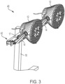
- lighting tower 10 may include a pair of light fixtures 12, with each light fixture 12 pivotally coupled to a base 14 to allow for adjustable orientation of the light fixture 12.
- each light fixture 12 may include, e.g., a housing, an interface plate, and an optional power supply unit, and the housing may encase various components of the light fixture such as, e.g., a set of LED modules secured to form a multi-module LED structure.
- light fixtures 12 need not be LED-based, and may be any appropriate light-emitting device.
- Lighting tower 10 further includes a vertically-extending light pole 16, a first crossbeam 17, and a second crossbeam 18.
- Light pole 16 and respective crossbeams 17, 18 may be formed of any suitable material, such as, e.g., steel, aluminum, wood, etc. Additionally, crossbeams 17, 18 may be coupled to light pole 16 through any suitable attachment means such as, e.g., welding, fasteners, etc. While light fixtures 12 are only shown as being mounted on first crossbeam 17, it is to be understood that one or more light fixtures 12 may also be mounted on second crossbeam 18, and that additional crossbeams (not shown) may be coupled to light pole 16. Alternatively, only one crossbeam may be utilized.
- the lighting tower 10 shown in FIGS. 1A-1B provides a mount adapter assembly 20 for the coupling of each light fixture 12 without the need for modifications to the crossbeams, as will be described in further detail below.
- Mount adapter assembly 20 in accordance with an aspect of the disclosure is shown in greater detail.
- Mount adapter assembly 20 may be formed of any appropriate material or combination of materials such as, e.g., aluminum, steel, plastic, etc.
- Mount adapter assembly 20 includes an upper mounting portion 22 and a lower clamping portion 30.
- Upper mounting portion 22 is configured to support the mounting of, e.g., the base 14 of a lighting fixture 12, as shown in FIGS. 1A-1B
- lower clamping portion 30 is configured to secure the mount adapter assembly 20 to an existing crossbeam without the need for modification to the crossbeam.
- Upper mounting portion 22 includes a top mounting portion wall 23, a first mounting portion sidewall 24, a second mounting portion sidewall 25, and a bottom mounting portion wall 26.
- An opening 27 may be formed between the top mounting portion wall 23, first mounting portion sidewall 24, second mounting portion sidewall 25, and bottom mounting portion wall 26 such that the interior of upper mounting portion 22 is visible and accessible.
- second mounting portion sidewall 25 may include an opening 28 formed therein to allow even further visibility and access into the upper mounting portion 22. While not shown in FIG. 2 , it is to be understood that first mounting portion sidewall 24 may also include an opening, and/or there may be no opening 28 formed in second mounting portion sidewall 25.
- the top mounting portion wall 23 may include a mounting hole 29, with the mounting hole 29 sized and configured to receive, e.g., mounting hardware utilized to secure the base 14 of a lighting fixture 12. While only one mounting hole 29 is shown in FIG. 2 , it is to be understood that additional mounting holes in a plurality of different patterns may be incorporated into top mounting portion wall 23, enabling lighting fixtures 12 having various mounting schemes to be coupled to the upper mounting portion 22.
- the mounting hardware utilized to secure the base 14 may be any appropriate hardware such as, e.g., bolts, nuts, screws, etc.
- One or more of the openings 27, 28 may be utilized by a utility worker or technician to easily access a portion of the mounting hardware (e.g., a nut) so as to ensure a secure connection between the base 14 and the top mounting portion wall 23.
- upper mounting portion 22 is shown as being coupled to lower clamping portion 30.
- the coupling between upper mounting portion 22 and lower clamping portion 30 may be achieved through any appropriate method such as, e.g., welding, fastener(s), adhesive(s), etc.
- Lower clamping portion 30 may be arranged in a substantially inverted, U-shaped configuration, including a top clamping portion wall 31, a first clamping portion sidewall 32, and second clamping portion sidewall 33.
- the U-shaped configuration of lower clamping portion 30 may be achieved through any appropriate method such as, e.g., bending, stamping, welding, molding, etc.
- a pair of fasteners 34A, 34B are shown as extending through a pair of respective sleeves 35A, 35B, with the sleeves 35A, 35B disposed between first clamping portion sidewall 32 and second clamping portion sidewall 33.
- the fasteners 34A, 34B may be any appropriate fastener such as, e.g., a bolt-and-nut combination, a bar with a receptacle into which a securing pin is placed, or another fastening structure. Accordingly, as the fasteners 34A, 34B are tightened, a slight clamping force may be applied to both the first clamping portion sidewall 32 and the second clamping portion sidewall 33.
- the lower clamping portion 30 may be removably secured to, e.g., crossbeam 17, as is shown in FIGS. 1A-1B .
- a pair of fasteners 34A, 34B and a pair of sleeves 35A, 35B are shown, it is to be understood that fewer than two or more than two fasteners and/or sleeves may be utilized. Also, the sleeves 35A, 35B are optional, and may be omitted in some embodiments.
- the mount adapter assemblies 20 are capable of being mounted on a pre-existing crossbeam 17 without the need for modifications to the crossbeam 17 itself.
- the crossbeam 17 may be of a conventional size/shape (e.g., 2 inches tall by 4 inches wide), and thus the spacing between the first clamping portion sidewall 32 and the second clamping portion sidewall 33 may be sized accordingly, as may the spacing between the top clamping portion wall 31 and the sleeves 35A, 35B.
- mount adapter assembly 20 is not limited to one specific size and/or shape, and may be customized to fit various crossbeams having various dimensions.
- lighting configuration 40 in accordance with another aspect of the disclosure is illustrated.
- mount adapter assembly 20 which includes a first clamping portion sidewall 32 and a second clamping portion sidewall 33 being positioned at a relatively fixed distance apart
- lighting configuration 40 utilizes a mount adapter assembly 42 having an adjustable-width lower clamping portion.
- mount adapter assembly 42 is capable of being utilized on crossbeams having various widths.
- Mount adapter assembly 42 includes an L-shaped stationary portion 44 having a horizontally-extending top surface 45 and a vertically-extending rear sidewall 46.
- the L-shaped stationary portion 44 may be formed of any appropriate material or combination of materials such as, e.g., aluminum, steel, plastic, etc., and may be formed by any appropriate method such as, e.g., bending, stamping, welding, molding, etc.
- Sliding portion 48 Movably coupled to L-shaped stationary portion 44 is a sliding portion 48.
- Sliding portion 48 includes a horizontally-extending top portion 49 and vertically-extending lower wall 50.
- Top portion 49 and lower wall 50 are spaced apart by the approximate thickness of top stationary portion wall 45, but are coupled together by way of tongues 53.
- One end of each tongue 53 is affixed or otherwise attached to the lower wall 50, while the other end of each tongue 53 is affixed or otherwise attached to the top portion 49.
- one end of each tongue 53 may form a respective mortice-and-tenon joint 59A, 59B with the top portion 49. While only one tongue 53 is shown in FIGS. 4A-4B (associated with mortice-and-tenon joint 59A ), it is to be understood that a second tongue 53 is also present (and associated with mortice-and-tenon joint 59B ).
- Top stationary portion wall 45 of L-shaped stationary portion 44 further includes a plurality of elongated slots 54A, 54B, 54C, 54D.
- Elongated slots 54A, 54B, 54C, 54D may be configured to enable sliding portion 48 to move horizontally relative to L-shaped stationary portion 44, thereby allowing for the distance between vertically-extending rear sidewall 46 and vertically-extending lower wall 50 to be varied. As is shown in FIGS.
- the tongues 53 may extend through two of the elongated slots (i.e., slots 54B and 54C ), while a pair of fasteners 52A, 52B may extend through the other two elongated slots (i.e., slots 54A and 54D ) such that the sliding portion 48 is capable of being secured at a desired position relative to the elongated slots 54A, 54B, 54C, 54D formed in the L-shaped stationary portion 44.
- the fasteners 52A, 52B may be any appropriate fastener such as, e.g., a bolt-and-nut combination, a bar with a receptacle into which a securing pin is placed, or another fastening structure.
- top portion 49 may include additional through-holes 58A, 58B position and sized for the insertion of additional fasteners.
- fasteners 52A, 52B could be inserted through the through-holes 58A, 58B, as opposed to the positions as shown in FIGS. 4A-4B .
- the tongues 53 not only act to couple the top portion 49 and lower wall 50 of the sliding portion 48, but they also act to square (or hold parallel) the lower wall 50 relative to the vertically-extending rear sidewall 46, regardless of the position of the sliding portion 48 relative to the elongated slots 54A, 54B, 54C, 54D. That is, as the tongues 53 extend through a pair of elongated slots 54B, 54C, any twisting of the sliding portion 48 relative to the L-shaped stationary portion 44 can be substantially avoided.
- a distal end region of the horizontally-extending top surface 45 may include a plurality of mounting holes 55, 56, with the mounting holes 55, 56 sized and configured to receive, e.g., mounting hardware utilized to secure the base 14 of a lighting fixture 12. While a single center mounting hole 55 and four surrounding mounting holes 56 are shown in FIGS. 4A-4B , it is to be understood that additional mounting holes in a plurality of different patterns may be incorporated into horizontally-extending top surface 45, enabling lighting fixtures 12 having various mounting schemes to be coupled to mount adapter assemblies 42.
- the mounting hardware utilized to secure the base 14 may be any appropriate hardware such as, e.g., bolts, nuts, screws, etc.
- a pair of fasteners 51A, 51B are shown as extending through both the vertically-extending rear sidewall 46 and the lower wall 50.
- the fasteners 51A, 51B may be any appropriate fastener such as, e.g., a bolt-and-nut combination, a bar with a receptacle into which a securing pin is placed, or another fastening structure.
- the fasteners optionally may be held within sleeves such as those shown in the embodiment of FIG. 2 .
- the sliding portion 48 is capable of moving relative to the L-shaped stationary portion 44, and a clamping force may be applied to both the vertically-extending rear sidewall 46 and the lower wall 50 over, e.g., a crossbeam 17, as is shown in FIG. 3 .
- the mount adapter assemblies 42 are capable of being mounted on a pre-existing crossbeam 17 without the need for modifications to the crossbeam 17 itself.
- the mount adapter assemblies 42 are configured so as to be usable with crossbeams of varying widths, thereby eliminating the need for multiple versions of mount adapter assemblies for specific crossbeam widths.
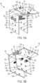
- mount adapter assembly 60 in accordance with another aspect of the disclosure is illustrated. Similar to mount adapter assembly 42 described above with respect to FIGS. 3-4B , mount adapter assembly 60 is configured to be usable on crossbeams of varying widths. However, unlike mount adapter assembly 42, mount adapter assembly 60 is also configured to be usable on crossbeams having varying heights, as will be set forth in further detail below.
- Mount adapter assembly 60 includes an L-shaped stationary portion 64 having a horizontally-extending top surface 65 and a vertically-extending rear sidewall 66.
- the L-shaped stationary portion 64 may be formed of any appropriate material or combination of materials such as, e.g., aluminum, steel, plastic, etc., and may be formed by any appropriate method such as, e.g., bending, stamping, welding, molding, etc.
- Sliding portion 68 Movably coupled to L-shaped stationary portion 64 is a sliding portion 68.
- Sliding portion 68 includes a horizontally-extending top portion 69 and a vertically-extending lower wall 70.
- Top portion 69 and lower wall 70 are spaced apart by the approximate thickness of top stationary portion wall 65, but are coupled together by way of tongues 73.
- One end of each tongue 73 is affixed or otherwise attached to the lower wall 70, while the other end of each tongue 73 is affixed or otherwise attached to the top portion 69.
- one end of each tongue 73 may form a respective mortice-and-tenon joint 79A, 79B with the top portion 69. While only one tongue 73 is shown in FIGS. 5A-5B (associated with mortice-and-tenon joint 79A ), it is to be understood that a second tongue 73 is also present (and associated with mortice-and-tenon joint 79B ).
- Top stationary portion wall 65 of L-shaped stationary portion 64 further includes a plurality of elongated slots 74A, 74B, 74C, 74D.
- Elongated slots 74A, 74B, 74C, 74D may be configured to enable sliding portion 68 to move horizontally relative to L-shaped stationary portion 64, thereby allowing for the distance between vertically-extending rear sidewall 66 and vertically-extending lower wall 70 to be varied. As is shown in FIGS.
- the tongues 73 may extend through two of the elongated slots (i.e., slots 74B and 74C ), while a pair of fasteners 72A, 72B may extend through the other two elongated slots (i.e., slots 74A and 74D ) such that the sliding portion 68 is capable of being secured at a desired position relative to the elongated slots 74A, 74B, 74C, 74D formed in the L-shaped stationary portion 64.
- the fasteners 72A, 72B may be any appropriate fastener such as, e.g., a bolt-and-nut combination, a bar with a receptacle into which a securing pin is placed, or another fastening structure.
- top portion 69 may include additional through-holes 78A, 78B position and sized for the insertion of additional fasteners.
- fasteners 72A, 72B could be inserted through the through-holes 78A, 78B, as opposed to the positions as shown in FIGS. 5A-5B .
- the tongues 73 not only act to couple the top portion 69 and lower wall 70 of the sliding portion 68, but they also act to square the lower wall 70 relative to the vertically-extending rear sidewall 66, regardless of the position of the sliding portion 68 relative to the elongated slots 74A, 74B, 74C, 74D. That is, as the tongues 73 extend through a pair of elongated slots 74B, 74C, any twisting of the sliding portion 68 relative to the L-shaped stationary portion 64 can be substantially avoided.
- a distal end region of the horizontally-extending top surface 65 may include a plurality of mounting holes 75, 76, with the mounting holes 75, 76 sized and configured to receive, e.g., mounting hardware utilized to secure the base 14 of a lighting fixture 12. While a single center mounting hole 75 and four surrounding mounting holes 76 are shown in FIGS. 5A-5B , it is to be understood that additional mounting holes in a plurality of different patterns may be incorporated into horizontally-extending top surface 65, enabling lighting fixtures 12 having various mounting schemes to be coupled to mount adapter assemblies 60.
- the mounting hardware utilized to secure the base 14 may be any appropriate hardware such as, e.g., bolts, nuts, screws, etc.
- a pair of fasteners 71A, 71B are shown as extending through both the vertically-extending rear sidewall 66 and the lower wall 70.
- the fasteners 71A, 71B may be any appropriate fastener such as, e.g., a bolt-and-nut combination, a bar with a receptacle into which a securing pin is placed, or another fastening structure.
- the fasteners optionally may be held within sleeves such as those shown in the embodiment of FIG. 2 .
- the sliding portion 68 is capable of moving relative to the L-shaped stationary portion 64, and a clamping force may be applied to both the vertically-extending rear sidewall 66 and the lower wall 70 over, e.g., a crossbeam 17.
- the mount adapter assemblies 60 are capable of being mounted on a pre-existing crossbeam 17 without the need for modifications to the crossbeam 17 itself.
- the mount adapter assemblies 60 are configured so as to be usable with crossbeams of varying widths, thereby eliminating the need for multiple versions of mount adapter assemblies for specific crossbeam widths.
- mount adapter assemblies 60 are also configured to be usable with crossbeams of varying heights.
- mount adapter assemblies 60 include a plurality of aligned through-hole pairs in both the vertically-extending rear sidewall 66 and the lower wall 70 to accommodate not only crossbeams of varying widths, but also varying heights.
- the vertically-extending rear sidewall 66 includes associated pairs of through-holes 80A, 80B and 82A, 82B, which are horizontally aligned with respective associated pairs of through-holes 81A, 81B and 83A, 83B in the lower wall 70.
- mount adapter assemblies 60 can be configured for use on crossbeams of many sizes, including crossbeams of varying widths and heights.
Landscapes
- Engineering & Computer Science (AREA)
- General Engineering & Computer Science (AREA)
- Non-Portable Lighting Devices Or Systems Thereof (AREA)
- Fastening Of Light Sources Or Lamp Holders (AREA)
Claims (7)
- Montageadapteranordnung (42) zur Verwendung mit Beleuchtungskörpern (12) an einem Beleuchtungsturm, umfassend:
einen L-förmigen stationären Abschnitt (44), wobei der L-förmige stationäre Abschnitt umfasst:eine horizontal verlaufende obere Fläche (45) undeine vertikal verlaufende hintere Seitenwand (46),wobei die horizontal verlaufende obere Fläche (45) mindestens ein Montageloch (55,56), das für die Verbindung eines Beleuchtungskörpers (12) mit der Montageadapteranordnung (42) konfiguriert ist, und eine Vielzahl von länglichen Schlitzen (54A-D) einschließt;einen Gleitabschnitt (48), wobei der Gleitabschnitt umfasst:einem horizontal verlaufenden oberen Abschnitt (49) undeine vertikal verlaufende untere Wand (50); undmindestens ein Befestigungselement (51A-B), das sich sowohl durch die vertikal verlaufende hintere Seitenwand (46) des L-förmigen stationären Abschnitts (44) als auch durch die vertikal verlaufende untere Wand (50) des Gleitabschnitts (48) erstreckt, um eine Klemmkraft zwischen der vertikal verlaufenden hinteren Seitenwand und der vertikal verlaufenden unteren Wand auszuüben, und wobei der horizontal verlaufende obere Abschnitt (49) und die vertikal verlaufende untere Wand (50) des Gleitabschnitts durch ein Paar Zungen (53) gekoppelt sind, die sich durch ein Paar der länglichen Schlitze (54A-D) erstrecken. - Montageadapteranordnung nach Anspruch 1, wobei das Zungenpaar so konfiguriert ist, dass die vertikal verlaufende untere Wand parallel zur vertikal verlaufenden hinteren Seitenwand gehalten wird.
- Montageadapteranordnung nach Anspruch 1, ferner umfassend mindestens ein zusätzliches Befestigungselement, das so konfiguriert ist, dass es sich durch mindestens einen der länglichen Schlitze erstreckt, um den Gleitabschnitt relativ zu dem L-förmigen stationären Abschnitt zu sichern.
- Montageadapteranordnung nach Anspruch 1, wobei das mindestens eine Befestigungselement ein Befestigungselementpaar umfasst.
- Montageadapteranordnung nach Anspruch 4, ferner umfassend eine Vielzahl von zugehörigen Durchgangslochpaaren, die durch die jeweilige vertikal verlaufende untere Wand und die vertikal verlaufende hintere Seitenwand gebildet sind, wobei die Durchgangslochpaare vertikal zueinander positioniert sind und so konfiguriert sind, dass das Befestigungselementpaar an verschiedenen Punkten mit der vertikal verlaufenden unteren Wand und der vertikal verlaufenden hinteren Seitenwand verbunden werden kann.
- Montageadapteranordnung nach Anspruch 1, wobei die vertikal verlaufende hintere Seitenwand eine Vielzahl von Durchgangslochpaaren einschließt, die vertikal zueinander positioniert sind.
- Montageadapteranordnung nach Anspruch 6, wobei die vertikal verlaufende untere Wand eine Vielzahl von Durchgangslochpaaren einschließt, die relativ zueinander positioniert sind.
Applications Claiming Priority (2)
| Application Number | Priority Date | Filing Date | Title |
|---|---|---|---|
| US16/711,512 US10907810B1 (en) | 2019-12-12 | 2019-12-12 | Universal mount adapter for light fixtures |
| PCT/EP2020/085003 WO2021116068A1 (en) | 2019-12-12 | 2020-12-08 | Universal mount adapter for light fixtures |
Publications (2)
| Publication Number | Publication Date |
|---|---|
| EP4073428A1 EP4073428A1 (de) | 2022-10-19 |
| EP4073428B1 true EP4073428B1 (de) | 2025-02-12 |
Family
ID=73790092
Family Applications (1)
| Application Number | Title | Priority Date | Filing Date |
|---|---|---|---|
| EP20821176.3A Active EP4073428B1 (de) | 2019-12-12 | 2020-12-08 | Universal-montage-adapter zur befestigung von beleuchtungseinrichtungen |
Country Status (3)
| Country | Link |
|---|---|
| US (1) | US10907810B1 (de) |
| EP (1) | EP4073428B1 (de) |
| WO (1) | WO2021116068A1 (de) |
Families Citing this family (7)
| Publication number | Priority date | Publication date | Assignee | Title |
|---|---|---|---|---|
| US11665996B1 (en) * | 2021-09-21 | 2023-06-06 | Shanika Marie Finley-James | String trimmer lighting system and method of use |
| WO2023057378A1 (en) | 2021-10-05 | 2023-04-13 | Signify Holding B.V. | Crossarm retrofit system |
| US12222116B2 (en) | 2021-12-30 | 2025-02-11 | Midea Group Co., Ltd. | Adjustable mounting assembly for air conditioning outdoor unit |
| US12203665B2 (en) | 2021-12-30 | 2025-01-21 | Midea Group Co., Ltd. | Hybrid window air conditioning unit |
| US12529484B2 (en) | 2021-12-30 | 2026-01-20 | Midea Group Co., Ltd. | Adjustable mounting assembly for air conditioning outdoor unit |
| US12234999B2 (en) | 2022-03-02 | 2025-02-25 | Midea Group Co., Ltd. | Window-mounted air conditioner |
| US12235013B2 (en) | 2022-12-15 | 2025-02-25 | Midea Group Co., Ltd. | Adjustable bracket for window air conditioner |
Family Cites Families (14)
| Publication number | Priority date | Publication date | Assignee | Title |
|---|---|---|---|---|
| DE8802554U1 (de) * | 1988-02-26 | 1988-04-14 | Aerolux H.-J. Mähl Inh. Karl Metz, 2000 Norderstedt | Klemmhalterung für Sonnenschutzvorrichtungen |
| US4852840A (en) * | 1988-09-06 | 1989-08-01 | Marks Dale H | Clamp for mounting a device to a tubular |
| US4885667A (en) * | 1989-02-23 | 1989-12-05 | Boynton Selden | Gooseneck lamp and magnifier with improved clamp assembly |
| US8337058B2 (en) | 2005-01-18 | 2012-12-25 | Musco Corporation | Single arm mogul mount for sports lighting fixtures |
| US7391624B2 (en) * | 2006-05-11 | 2008-06-24 | Physical Systems, Inc. | Adjustable mounting bracket |
| US20080089071A1 (en) * | 2006-10-12 | 2008-04-17 | Chin-Wen Wang | Lamp structure with adjustable projection angle |
| US7988343B2 (en) * | 2007-04-26 | 2011-08-02 | Palmisano Jr Lester J | Easy-glide offshore ready light tower system |
| US8931932B2 (en) * | 2010-04-16 | 2015-01-13 | G.H.L. International, Inc. | Moisture release valve for an outdoor light fixture |
| US8960971B1 (en) | 2012-04-02 | 2015-02-24 | Cooper Technologies Company | Adjustable mounting system for a luminaire |
| US8974102B2 (en) * | 2013-03-15 | 2015-03-10 | Weekend Concepts, Inc. | Vehicular lighting system |
| US9145084B2 (en) * | 2013-09-18 | 2015-09-29 | Omix-Ada, Inc. | Auxiliary light mount assembly for tubular bumpers |
| US9896021B2 (en) * | 2014-09-10 | 2018-02-20 | John SPEROPOULOS | Boat trailer light mount assembly |
| US20160319988A1 (en) * | 2015-05-03 | 2016-11-03 | Lucifer Lighting Company | Apparatuses Including Fixtures and/or Fixture Mounts and Related Methods |
| US10188006B2 (en) * | 2015-12-16 | 2019-01-22 | Minka Lighting, Inc. | Bracket mount assembly for light fixtures |
-
2019
- 2019-12-12 US US16/711,512 patent/US10907810B1/en active Active
-
2020
- 2020-12-08 EP EP20821176.3A patent/EP4073428B1/de active Active
- 2020-12-08 WO PCT/EP2020/085003 patent/WO2021116068A1/en not_active Ceased
Also Published As
| Publication number | Publication date |
|---|---|
| US10907810B1 (en) | 2021-02-02 |
| WO2021116068A1 (en) | 2021-06-17 |
| EP4073428A1 (de) | 2022-10-19 |
Similar Documents
| Publication | Publication Date | Title |
|---|---|---|
| EP4073428B1 (de) | Universal-montage-adapter zur befestigung von beleuchtungseinrichtungen | |
| KR102004492B1 (ko) | 상품 디스플레이를 위한 led 발광 조립체 및 발광 방법 | |
| US9464778B2 (en) | Lighting device utilizing a double fresnel lens | |
| US9506631B2 (en) | Profile rail, connecting element, illuminating module, lighting system and light box | |
| AU2012238294B2 (en) | Edge-lit luminaire | |
| US20170219200A1 (en) | High intensity light-emitting diode luminaire assembly | |
| US20090290343A1 (en) | Lighting fixture | |
| JP2011014317A (ja) | 照明体及び照明装置 | |
| US20110063844A1 (en) | LED Lighting Assembly and Method of Lighting for a Merchandise Display | |
| US10274171B2 (en) | Adjustable LED light fixture for use in a troffer | |
| KR101726369B1 (ko) | 용이한 설치 및 고정이 가능한 엘이디 경관 조명장치 | |
| KR101506492B1 (ko) | 터널등용 하우징 | |
| JP2011014316A (ja) | 照明装置 | |
| EP1934518A2 (de) | Beleuchtungsvorrichtung | |
| KR101118965B1 (ko) | 복합 렌즈를 포함하는 엘이디 조명기구 시스템 | |
| US11098880B2 (en) | Luminaire with improved assembly, installation, and wireless functionality | |
| KR101079860B1 (ko) | 엘이디 조명기구 | |
| KR102117358B1 (ko) | 경관조명장치 | |
| KR101922616B1 (ko) | 문양의 교체가 가능한 엘이디 조명 장치 | |
| KR101635556B1 (ko) | 평판 조명기기 | |
| JPWO2019244231A1 (ja) | 人工栽培装置および人工栽培装置のled照明具の通電方法 | |
| KR100970110B1 (ko) | 등기구 일체형 led 조명장치 | |
| KR20110110490A (ko) | 조명각을 다르게 한 고효율 확장형 엘이디조명등 | |
| KR200459190Y1 (ko) | 조명장치 | |
| KR101731768B1 (ko) | 형광등 장착형 led 조명기기 |
Legal Events
| Date | Code | Title | Description |
|---|---|---|---|
| STAA | Information on the status of an ep patent application or granted ep patent |
Free format text: STATUS: UNKNOWN |
|
| STAA | Information on the status of an ep patent application or granted ep patent |
Free format text: STATUS: THE INTERNATIONAL PUBLICATION HAS BEEN MADE |
|
| PUAI | Public reference made under article 153(3) epc to a published international application that has entered the european phase |
Free format text: ORIGINAL CODE: 0009012 |
|
| STAA | Information on the status of an ep patent application or granted ep patent |
Free format text: STATUS: REQUEST FOR EXAMINATION WAS MADE |
|
| 17P | Request for examination filed |
Effective date: 20220712 |
|
| AK | Designated contracting states |
Kind code of ref document: A1 Designated state(s): AL AT BE BG CH CY CZ DE DK EE ES FI FR GB GR HR HU IE IS IT LI LT LU LV MC MK MT NL NO PL PT RO RS SE SI SK SM TR |
|
| DAV | Request for validation of the european patent (deleted) | ||
| DAX | Request for extension of the european patent (deleted) | ||
| GRAP | Despatch of communication of intention to grant a patent |
Free format text: ORIGINAL CODE: EPIDOSNIGR1 |
|
| STAA | Information on the status of an ep patent application or granted ep patent |
Free format text: STATUS: GRANT OF PATENT IS INTENDED |
|
| INTG | Intention to grant announced |
Effective date: 20240816 |
|
| GRAS | Grant fee paid |
Free format text: ORIGINAL CODE: EPIDOSNIGR3 |
|
| P01 | Opt-out of the competence of the unified patent court (upc) registered |
Free format text: CASE NUMBER: APP_59486/2024 Effective date: 20241101 |
|
| GRAA | (expected) grant |
Free format text: ORIGINAL CODE: 0009210 |
|
| STAA | Information on the status of an ep patent application or granted ep patent |
Free format text: STATUS: THE PATENT HAS BEEN GRANTED |
|
| AK | Designated contracting states |
Kind code of ref document: B1 Designated state(s): AL AT BE BG CH CY CZ DE DK EE ES FI FR GB GR HR HU IE IS IT LI LT LU LV MC MK MT NL NO PL PT RO RS SE SI SK SM TR |
|
| REG | Reference to a national code |
Ref country code: GB Ref legal event code: FG4D |
|
| REG | Reference to a national code |
Ref country code: CH Ref legal event code: EP |
|
| REG | Reference to a national code |
Ref country code: DE Ref legal event code: R096 Ref document number: 602020046029 Country of ref document: DE |
|
| REG | Reference to a national code |
Ref country code: IE Ref legal event code: FG4D |
|
| REG | Reference to a national code |
Ref country code: NL Ref legal event code: MP Effective date: 20250212 |
|
| PG25 | Lapsed in a contracting state [announced via postgrant information from national office to epo] |
Ref country code: RS Free format text: LAPSE BECAUSE OF FAILURE TO SUBMIT A TRANSLATION OF THE DESCRIPTION OR TO PAY THE FEE WITHIN THE PRESCRIBED TIME-LIMIT Effective date: 20250512 |
|
| PG25 | Lapsed in a contracting state [announced via postgrant information from national office to epo] |
Ref country code: FI Free format text: LAPSE BECAUSE OF FAILURE TO SUBMIT A TRANSLATION OF THE DESCRIPTION OR TO PAY THE FEE WITHIN THE PRESCRIBED TIME-LIMIT Effective date: 20250212 |
|
| PG25 | Lapsed in a contracting state [announced via postgrant information from national office to epo] |
Ref country code: PL Free format text: LAPSE BECAUSE OF FAILURE TO SUBMIT A TRANSLATION OF THE DESCRIPTION OR TO PAY THE FEE WITHIN THE PRESCRIBED TIME-LIMIT Effective date: 20250212 |
|
| PG25 | Lapsed in a contracting state [announced via postgrant information from national office to epo] |
Ref country code: ES Free format text: LAPSE BECAUSE OF FAILURE TO SUBMIT A TRANSLATION OF THE DESCRIPTION OR TO PAY THE FEE WITHIN THE PRESCRIBED TIME-LIMIT Effective date: 20250212 |
|
| REG | Reference to a national code |
Ref country code: LT Ref legal event code: MG9D |
|
| PG25 | Lapsed in a contracting state [announced via postgrant information from national office to epo] |
Ref country code: NO Free format text: LAPSE BECAUSE OF FAILURE TO SUBMIT A TRANSLATION OF THE DESCRIPTION OR TO PAY THE FEE WITHIN THE PRESCRIBED TIME-LIMIT Effective date: 20250512 Ref country code: IS Free format text: LAPSE BECAUSE OF FAILURE TO SUBMIT A TRANSLATION OF THE DESCRIPTION OR TO PAY THE FEE WITHIN THE PRESCRIBED TIME-LIMIT Effective date: 20250612 |
|
| PG25 | Lapsed in a contracting state [announced via postgrant information from national office to epo] |
Ref country code: NL Free format text: LAPSE BECAUSE OF FAILURE TO SUBMIT A TRANSLATION OF THE DESCRIPTION OR TO PAY THE FEE WITHIN THE PRESCRIBED TIME-LIMIT Effective date: 20250212 |
|
| PG25 | Lapsed in a contracting state [announced via postgrant information from national office to epo] |
Ref country code: HR Free format text: LAPSE BECAUSE OF FAILURE TO SUBMIT A TRANSLATION OF THE DESCRIPTION OR TO PAY THE FEE WITHIN THE PRESCRIBED TIME-LIMIT Effective date: 20250212 |
|
| PG25 | Lapsed in a contracting state [announced via postgrant information from national office to epo] |
Ref country code: LV Free format text: LAPSE BECAUSE OF FAILURE TO SUBMIT A TRANSLATION OF THE DESCRIPTION OR TO PAY THE FEE WITHIN THE PRESCRIBED TIME-LIMIT Effective date: 20250212 Ref country code: PT Free format text: LAPSE BECAUSE OF FAILURE TO SUBMIT A TRANSLATION OF THE DESCRIPTION OR TO PAY THE FEE WITHIN THE PRESCRIBED TIME-LIMIT Effective date: 20250612 |
|
| PG25 | Lapsed in a contracting state [announced via postgrant information from national office to epo] |
Ref country code: BG Free format text: LAPSE BECAUSE OF FAILURE TO SUBMIT A TRANSLATION OF THE DESCRIPTION OR TO PAY THE FEE WITHIN THE PRESCRIBED TIME-LIMIT Effective date: 20250212 Ref country code: GR Free format text: LAPSE BECAUSE OF FAILURE TO SUBMIT A TRANSLATION OF THE DESCRIPTION OR TO PAY THE FEE WITHIN THE PRESCRIBED TIME-LIMIT Effective date: 20250513 |
|
| REG | Reference to a national code |
Ref country code: AT Ref legal event code: MK05 Ref document number: 1766333 Country of ref document: AT Kind code of ref document: T Effective date: 20250212 |
|
| PG25 | Lapsed in a contracting state [announced via postgrant information from national office to epo] |
Ref country code: SE Free format text: LAPSE BECAUSE OF FAILURE TO SUBMIT A TRANSLATION OF THE DESCRIPTION OR TO PAY THE FEE WITHIN THE PRESCRIBED TIME-LIMIT Effective date: 20250212 |
|
| PG25 | Lapsed in a contracting state [announced via postgrant information from national office to epo] |
Ref country code: SM Free format text: LAPSE BECAUSE OF FAILURE TO SUBMIT A TRANSLATION OF THE DESCRIPTION OR TO PAY THE FEE WITHIN THE PRESCRIBED TIME-LIMIT Effective date: 20250212 |
|
| PG25 | Lapsed in a contracting state [announced via postgrant information from national office to epo] |
Ref country code: DK Free format text: LAPSE BECAUSE OF FAILURE TO SUBMIT A TRANSLATION OF THE DESCRIPTION OR TO PAY THE FEE WITHIN THE PRESCRIBED TIME-LIMIT Effective date: 20250212 |
|
| PG25 | Lapsed in a contracting state [announced via postgrant information from national office to epo] |
Ref country code: IT Free format text: LAPSE BECAUSE OF FAILURE TO SUBMIT A TRANSLATION OF THE DESCRIPTION OR TO PAY THE FEE WITHIN THE PRESCRIBED TIME-LIMIT Effective date: 20250212 |
|
| PG25 | Lapsed in a contracting state [announced via postgrant information from national office to epo] |
Ref country code: AT Free format text: LAPSE BECAUSE OF FAILURE TO SUBMIT A TRANSLATION OF THE DESCRIPTION OR TO PAY THE FEE WITHIN THE PRESCRIBED TIME-LIMIT Effective date: 20250212 |
|
| PG25 | Lapsed in a contracting state [announced via postgrant information from national office to epo] |
Ref country code: EE Free format text: LAPSE BECAUSE OF FAILURE TO SUBMIT A TRANSLATION OF THE DESCRIPTION OR TO PAY THE FEE WITHIN THE PRESCRIBED TIME-LIMIT Effective date: 20250212 Ref country code: CZ Free format text: LAPSE BECAUSE OF FAILURE TO SUBMIT A TRANSLATION OF THE DESCRIPTION OR TO PAY THE FEE WITHIN THE PRESCRIBED TIME-LIMIT Effective date: 20250212 |
|
| PG25 | Lapsed in a contracting state [announced via postgrant information from national office to epo] |
Ref country code: RO Free format text: LAPSE BECAUSE OF FAILURE TO SUBMIT A TRANSLATION OF THE DESCRIPTION OR TO PAY THE FEE WITHIN THE PRESCRIBED TIME-LIMIT Effective date: 20250212 |
|
| PG25 | Lapsed in a contracting state [announced via postgrant information from national office to epo] |
Ref country code: SK Free format text: LAPSE BECAUSE OF FAILURE TO SUBMIT A TRANSLATION OF THE DESCRIPTION OR TO PAY THE FEE WITHIN THE PRESCRIBED TIME-LIMIT Effective date: 20250212 |
|
| REG | Reference to a national code |
Ref country code: DE Ref legal event code: R097 Ref document number: 602020046029 Country of ref document: DE |
|
| PLBE | No opposition filed within time limit |
Free format text: ORIGINAL CODE: 0009261 |
|
| STAA | Information on the status of an ep patent application or granted ep patent |
Free format text: STATUS: NO OPPOSITION FILED WITHIN TIME LIMIT |
|
| PGFP | Annual fee paid to national office [announced via postgrant information from national office to epo] |
Ref country code: GB Payment date: 20251223 Year of fee payment: 6 |
|
| PGFP | Annual fee paid to national office [announced via postgrant information from national office to epo] |
Ref country code: FR Payment date: 20251230 Year of fee payment: 6 |
|
| 26N | No opposition filed |
Effective date: 20251113 |
|
| PGFP | Annual fee paid to national office [announced via postgrant information from national office to epo] |
Ref country code: DE Payment date: 20260220 Year of fee payment: 6 |