EP4073475B1 - Système de mesure vibronique destiné à mesurer un débit massique d'un milieu de mesure fluide et utilisation du système de mesure vibronique - Google Patents
Système de mesure vibronique destiné à mesurer un débit massique d'un milieu de mesure fluide et utilisation du système de mesure vibronique Download PDFInfo
- Publication number
- EP4073475B1 EP4073475B1 EP20811305.0A EP20811305A EP4073475B1 EP 4073475 B1 EP4073475 B1 EP 4073475B1 EP 20811305 A EP20811305 A EP 20811305A EP 4073475 B1 EP4073475 B1 EP 4073475B1
- Authority
- EP
- European Patent Office
- Prior art keywords
- magnetic field
- measuring system
- sensor
- measuring
- vibration
- Prior art date
- Legal status (The legal status is an assumption and is not a legal conclusion. Google has not performed a legal analysis and makes no representation as to the accuracy of the status listed.)
- Active
Links
Images



Classifications
-
- G—PHYSICS
- G01—MEASURING; TESTING
- G01F—MEASURING VOLUME, VOLUME FLOW, MASS FLOW OR LIQUID LEVEL; METERING BY VOLUME
- G01F1/00—Measuring the volume flow or mass flow of fluid or fluent solid material wherein the fluid passes through a meter in a continuous flow
- G01F1/76—Devices for measuring mass flow of a fluid or a fluent solid material
- G01F1/78—Direct mass flowmeters
- G01F1/80—Direct mass flowmeters operating by measuring pressure, force, momentum, or frequency of a fluid flow to which a rotational movement has been imparted
- G01F1/84—Coriolis or gyroscopic mass flowmeters
- G01F1/8409—Coriolis or gyroscopic mass flowmeters constructional details
- G01F1/8422—Coriolis or gyroscopic mass flowmeters constructional details exciters
-
- G—PHYSICS
- G01—MEASURING; TESTING
- G01F—MEASURING VOLUME, VOLUME FLOW, MASS FLOW OR LIQUID LEVEL; METERING BY VOLUME
- G01F1/00—Measuring the volume flow or mass flow of fluid or fluent solid material wherein the fluid passes through a meter in a continuous flow
- G01F1/76—Devices for measuring mass flow of a fluid or a fluent solid material
- G01F1/78—Direct mass flowmeters
- G01F1/80—Direct mass flowmeters operating by measuring pressure, force, momentum, or frequency of a fluid flow to which a rotational movement has been imparted
- G01F1/84—Coriolis or gyroscopic mass flowmeters
- G01F1/8409—Coriolis or gyroscopic mass flowmeters constructional details
- G01F1/8427—Coriolis or gyroscopic mass flowmeters constructional details detectors
-
- G—PHYSICS
- G01—MEASURING; TESTING
- G01F—MEASURING VOLUME, VOLUME FLOW, MASS FLOW OR LIQUID LEVEL; METERING BY VOLUME
- G01F1/00—Measuring the volume flow or mass flow of fluid or fluent solid material wherein the fluid passes through a meter in a continuous flow
- G01F1/76—Devices for measuring mass flow of a fluid or a fluent solid material
- G01F1/78—Direct mass flowmeters
- G01F1/80—Direct mass flowmeters operating by measuring pressure, force, momentum, or frequency of a fluid flow to which a rotational movement has been imparted
- G01F1/84—Coriolis or gyroscopic mass flowmeters
- G01F1/8409—Coriolis or gyroscopic mass flowmeters constructional details
- G01F1/8436—Coriolis or gyroscopic mass flowmeters constructional details signal processing
-
- G—PHYSICS
- G01—MEASURING; TESTING
- G01F—MEASURING VOLUME, VOLUME FLOW, MASS FLOW OR LIQUID LEVEL; METERING BY VOLUME
- G01F15/00—Details of, or accessories for, apparatus of groups G01F1/00 - G01F13/00 insofar as such details or appliances are not adapted to particular types of such apparatus
- G01F15/02—Compensating or correcting for variations in pressure, density or temperature
-
- G—PHYSICS
- G01—MEASURING; TESTING
- G01F—MEASURING VOLUME, VOLUME FLOW, MASS FLOW OR LIQUID LEVEL; METERING BY VOLUME
- G01F25/00—Testing or calibration of apparatus for measuring volume, volume flow or liquid level or for metering by volume
- G01F25/10—Testing or calibration of apparatus for measuring volume, volume flow or liquid level or for metering by volume of flowmeters
-
- G—PHYSICS
- G01—MEASURING; TESTING
- G01R—MEASURING ELECTRIC VARIABLES; MEASURING MAGNETIC VARIABLES
- G01R33/00—Arrangements or instruments for measuring magnetic variables
- G01R33/0058—Arrangements or instruments for measuring magnetic variables using bistable elements, e.g. Reed switches
-
- G—PHYSICS
- G01—MEASURING; TESTING
- G01R—MEASURING ELECTRIC VARIABLES; MEASURING MAGNETIC VARIABLES
- G01R33/00—Arrangements or instruments for measuring magnetic variables
- G01R33/02—Measuring direction or magnitude of magnetic fields or magnetic flux
- G01R33/06—Measuring direction or magnitude of magnetic fields or magnetic flux using galvano-magnetic devices
- G01R33/07—Hall effect devices
- G01R33/072—Constructional adaptation of the sensor to specific applications
-
- G—PHYSICS
- G01—MEASURING; TESTING
- G01F—MEASURING VOLUME, VOLUME FLOW, MASS FLOW OR LIQUID LEVEL; METERING BY VOLUME
- G01F15/00—Details of, or accessories for, apparatus of groups G01F1/00 - G01F13/00 insofar as such details or appliances are not adapted to particular types of such apparatus
- G01F15/007—Details of, or accessories for, apparatus of groups G01F1/00 - G01F13/00 insofar as such details or appliances are not adapted to particular types of such apparatus comprising means to prevent fraud
Definitions
- the invention relates to a vibronic measuring system, in particular a Coriolis mass flow measuring device, for measuring a mass flow of a fluid medium.
- a mass flow and/or a density of a medium flowing in a process line, for example a pipeline, for example a liquid, a gas or a dispersion
- measuring electronics usually formed by at least one microprocessor - as well as a vibronic measuring sensor of the vibration type, which is electrically connected to the same measuring system electronics and is formed during operation by the medium to be measured.
- Examples of such measuring systems are, among others, in EP-A 564 682 , EP-A 816 807 , EP-A 644 403 , the US-A 2002/0033043 the US-A 2006/0096390 , the US-A 2007/0062309 , the US-A 2007/0119264 , the US-A 2008/0011101 , the US-A 2008/0047362 , the US-A 2008/0190195 , the US-A 2008/0250871 , the US-A 2010/0005887 , the US-A 2010/0011882 , the US-A 2010/0257943 , the US-A 2011/0161017 , the US-A 2011/0178738 , the US-A 2011/0219872 , the US-A 2011/0265580 , the US-A 2011/0271756
- the measuring sensor of each of the measuring systems shown therein comprises at least one vibration element, which is typically a measuring tube which is at least partially straight and/or at least partially curved, for example U-, V-, S-, Z- or ⁇ -shaped, with one of a
- the lumen surrounded by the tube wall is designed to guide the medium, or - as is also the case in the WO-A 2018/160382 , the US-A 2016/0187176 or the WO-A 2019/068553 shown - for example, can also be designed as a displacer element placed within a lumen of a tube through which the measured substance flows.
- the at least one vibration element is designed to be contacted by the medium to be measured, for example to be flowed through and/or around by the medium to be measured, and to be allowed to vibrate during this time, in particular in such a way that there are useful vibrations, namely mechanical vibrations, around a rest position with a position that also depends on the density of the Medium's co-determined useful frequency, which can therefore be used as a measure of the density.
- bending vibrations at a natural resonance frequency typically serve as useful vibrations, for example those bending vibrations which correspond to a natural bending vibration basic mode inherent in the measuring sensor, in which the vibrations of the vibration element are such resonance vibrations that have exactly one antinode.
- the useful vibrations are typically designed in such a way that the same measuring tube oscillates around an imaginary vibration axis which imaginarily connects an inlet-side and an outlet-side end of the measuring tube in the manner of a cantilever clamped at one end, whereas in the case of measuring sensors with a straight measuring tube as a vibration element, the useful vibrations are mostly bending vibrations in a single imaginary vibration plane.
- each designed as a measuring tube these are usually integrated into the respective process line via a distributor piece extending between the measuring tubes and an inlet-side connecting flange on the inlet side and via an outlet-side distributor piece extending between the measuring tubes and an outlet-side connecting flange.
- the latter In the case of measuring sensors with a single measuring tube as a vibration element, the latter usually communicates with the process line via a connecting pipe opening on the inlet side and via a connecting pipe opening on the outlet side.
- measuring sensors with a single measuring tube as a vibration element each comprise at least one further vibration element, namely as a counter-oscillator, for example in the form of a tube, box or plate, but not contacted by the medium to be measured, which is coupled to the measuring tube on the inlet side to form a first coupling zone and which is coupled to the measuring tube on the outlet side to form a second coupling zone, and which essentially rests or oscillates in the opposite direction to the measuring tube during operation.
- the inner part of the sensor which is formed by means of a measuring tube and counter-oscillator, is usually held in a protective sensor housing solely by means of the two connecting pipes via which the measuring pipe communicates with the process line during operation, in particular in a way that enables the inner part to oscillate relative to the sensor housing Way.
- the US-A 52 91 792 the US-A 57 96 010 , the US-A 59 45 609 , the US-B 70 77 014 , the US-A 2007/0119264 , the WO-A 01/02 816 or even that one WO-A 99/40 394 shown measuring sensors with a single, essentially straight measuring tube, the latter and the counter-oscillator, as is quite common with conventional measuring sensors, are aligned essentially coaxially with one another, in that the counter-oscillator is designed as a substantially straight hollow cylinder and is arranged in the measuring sensor in such a way that the measuring tube is at least partially is covered by the counter-oscillator.
- the materials used for such counter-oscillators, especially when using titanium, tantalum or zirconium for the measuring tube, are usually comparatively inexpensive types of steel, such as structural steel or free-cutting steel.
- measurement sensors of the vibration type also have at least one electromechanical, typically also electrodynamic, vibration exciter which acts on the at least one vibration element during operation.
- the vibration exciter which is electrically connected to the aforementioned measuring system electronics by means of a pair of electrical connecting lines, for example in the form of connecting wires and/or in the form of conductor tracks of a flexible printed circuit board, serves in particular to be generated and appropriately conditioned by drive electronics provided in the measuring system electronics , namely to convert an electrical excitation power fed in by means of the same driver signal, at least to changing vibration properties of the at least one vibration element, into a driving force acting on the at least one vibration element at a point of application formed by the vibration exciter.
- the drive electronics are in particular also set up to adjust the driver signal by means of internal control so that it has a signal frequency corresponding to the useful frequency to be excited, which occasionally also changes over time, if necessary as with an oscillation amplitude predetermined by an excitation current, namely an electrical current of the driver signal.
- the driver signal can, for example, occasionally be switched off during operation of the measuring device, for example to enable the aforementioned free damped oscillations of the at least one vibration element or, for example, as mentioned at the beginning WO-A 2017143579 proposed to protect the drive electronics from overload.
- Vibration exciters of commercially available vibration-type measuring sensors are typically constructed in the manner of a voice coil operating according to the electrodynamic principle, namely an air coil-magnet arrangement, which is usually fixed to the latter by means of a vibration element - in the case of measuring sensors with a measuring tube and a counter-oscillator coupled to it - air coil, namely a coil that does not contain a magnetic core, but rather air, and a permanent magnet that interacts with the at least one air coil and serves as an anchor - for example, fixed to the aforementioned measuring tube - and in which the respective air coil is at least partially positioned in an air gap of the permanent magnet that carries a magnetic flux is.
- a voice coil operating according to the electrodynamic principle namely an air coil-magnet arrangement, which is usually fixed to the latter by means of a vibration element - in the case of measuring sensors with a measuring tube and a counter-oscillator coupled to it - air coil, namely a coil that does not contain a magnetic core,
- Permanent magnets and air coil are usually aligned so that they are essentially coaxial with one another, and are also set up to be moved relative to one another or in opposite directions, such that when the excitation current flows through the air coil, the permanent magnet and the air coil located in its air gap are in the essentially moved back and forth translationally.
- the vibration exciter is usually designed and placed in such a way that it engages the at least one measuring tube essentially centrally.
- a vibration exciter acting on a vibration element can be used, as mentioned at the beginning US-A 60 92 429 , for example by means of two vibration exciters fixed not in the center of the at least one vibration element, but rather on the inlet or outlet side of this vibration exciter for actively stimulating mechanical vibrations of the at least one vibration element or, as in the US-B 62 23 605 or the US-A 55 31 126 proposed, for example also be used by means of a vibration exciter acting between the at least one vibration element and the pickup housing.
- the resulting Coriolis vibrations correspond, for example, to that - sometimes also referred to as twist mode - Bending vibration mode in which the measuring tube carries out torsional vibrations about an imaginary torsional vibration axis aligned perpendicular to the mentioned imaginary vibration axis, whereas in the case of a straight measuring tube as a vibration element, the useful vibrations of which are designed as bending vibrations in a single imaginary vibration plane, the Coriolis vibrations, for example, are essentially coplanar with the useful vibrations Bending vibrations are.
- measuring sensors of the type in question also have two or more along the at least one vibration element spaced apart, for example each by means of its own pair of electrical connecting lines with a vibration sensor electrically connected in the aforementioned measuring system electronics.
- Each of the vibration sensors is set up to detect the aforementioned vibration movements at a respective measuring point and to convert them into an electrical vibration measurement signal representing the same vibration movements, which has a useful component, namely a (spectral) signal or namely a AC voltage component with a (signal) frequency corresponding to the useful frequency and a (signal) amplitude dependent on the useful frequency and a magnetic flux established in the respective vibration sensor, and the vibration measurement signal from the measuring system electronics, for example a measurement formed by at least one microprocessor - and control electronics of the measuring system electronics, for further, if necessary digital processing.
- a useful component namely a (spectral) signal or namely a AC voltage component with a (signal) frequency corresponding to the useful frequency and a (signal) amplitude dependent on the useful frequency and a magnetic flux established in the respective vibration sensor
- the vibration measurement signal from the measuring system electronics, for example a measurement formed by at least one microprocessor - and control electronics of the measuring system electronics, for further, if necessary digital processing
- the at least two vibration sensors are designed and arranged in such a way that the aforementioned useful component of the vibration measurement signals generated thereby also each have a phase angle that is dependent on the mass flow, so that a transit time or phase difference that is dependent on the mass flow can be measured between the useful components of both vibration measurement signals. Based on the same phase difference, the measuring system electronics repeatedly determine mass flow measurement values that represent the mass flow.
- the density and/or the viscosity of the medium can also be measured - for example based on the useful frequency and/or on an electrical excitation power required for the excitation or maintenance of the useful vibrations or a damping of the useful vibrations determined based on this measured and output by the measuring system electronics together with the measured mass flow in the form of qualified measured values.
- the two vibration sensors are designed as electrodynamic vibration sensors, in particular in the same way as the at least one vibration exciter, each formed by means of an air coil-magnet arrangement - here serving as a moving coil - in which an air coil is also at least partially in an air gap carrying a magnetic flux of an associated permanent magnet is positioned ("immersed") and in which the air coil and permanent magnet are also set up to be moved relative to one another in order to generate an induction voltage, such that the air coil is essentially moved back and forth translationally in the air gap.
- the permanent magnet and the air coil are usually aligned so that they are essentially coaxial with one another.
- phase angles of the useful components of each of the vibration measurement signals can change over time despite a constant mass current or that the phase difference established between the useful components can occasionally have an interference component that is not dependent on the mass flow, such that a significant phase error, namely a no longer negligible additional change in the phase difference can be observed.
- phase errors can occur in particular in the case that the respective measuring system, in particular its respective measuring sensor, is in the vicinity of one or more electric motors , transformers, (electric) magnets, inverters or other high electrical currents, especially direct currents, are stationed in leading system parts, and therefore occasionally very strong ones external, namely from outside the measuring system, but is also exposed to an additional magnetic field propagating within its measuring sensor.
- one object of the invention is to improve vibronic measuring systems, not least Coriolis mass flow measuring devices, in such a way that the presence of an external magnetic field or its influence on the measuring accuracy is at least detected, for example in a timely manner can be reported accordingly.
- the first magnetic field signal is an analog signal, for example continuous in value and time, for example with a voltage dependent on the third magnetic flux and/or on its surface density.
- the measuring system electronics are further set up to use the first magnetic field signal to assign key figure values for at least one magnetic field key figure, for example an influence on the measurement sensor by the external magnetic field and/or an influence on at least one of the first and second magnetic fluxes calculate, for example in such a way that the same magnetic field index depends on a deviation of the first magnetic flux from the second magnetic flux and / or evaluates and / or quantifies the same deviation or that the same magnetic field index depends on a deviation of the first magnetic flux from a previously determined one Reference value is dependent and/or the same deviation is evaluated and/or quantified.
- the first magnetic field signal is an analog signal, for example of continuous value and time, for example with a voltage that depends on the third magnetic flux and / or its surface density
- the measuring system electronics are also set up, one or more key figure values for the magnetic field key figure, each with one or more reference values determined for the magnetic field key figure, for example by the manufacturer of the Coriolis mass flow measuring device and / or during the manufacture of the Coriolis mass flow measuring device, for example one or more one reduced functionality of the measuring sensor and / or one or more reference values representing a malfunction of the measuring sensor and / or one or more reference values representing a Coriolis mass flow measuring device that is no longer intact.
- the measuring system electronics is also set up to determine whether one or more key figure values for the magnetic field key figure is greater than the at least one reference value for the magnetic field key figure, for example if one or more key figure values for the magnetic field key figure is greater than one or more reference values representing reduced functionality of the measuring sensor and/or is greater than one or more reference values representing a malfunction of the measuring sensor and/or is greater than one or more reference values representing a no longer intact Coriolis mass flow measuring device, one of these to issue a signaling message.
- the measuring system electronics have a non-volatile electronic data memory which is set up to hold digital data, in particular even without an applied operating voltage, in particular one or more previously determined reference values for the magnetic field key figure.
- the electronic data storage contains one or more reference values for the magnetic field characteristic, for example one or more reduced ones, determined in advance by the manufacturer of the measuring system and/or during the manufacture of the measuring system and/or during operation of the measuring system Reference values representing the functionality of the measuring sensor and/or namely one or more reference values representing a malfunction of the measuring sensor are stored.
- the measuring system electronics can, if necessary, also be set up to compare one or more key figure values for the magnetic field key figure with one or more reference values for the magnetic field key figure stored in the data memory.
- the first magnetic field detector is formed by at least one Hall sensor.
- the first magnetic field detector is formed by means of at least one reed switch.
- the first magnetic field detector is positioned less far away from the first vibration sensor than from the second vibration sensor and/or less than 5 cm away from the first vibration sensor.
- the measuring and control electronics have a first analog-to-digital converter for the first vibration measurement signal and a second analog-to-digital converter for the second vibration measurement signal. Further developing this embodiment of the invention, the measuring system electronics also have a third analog-to-digital converter for the first magnetic field signal.
- the first vibration sensor is formed by means of a first moving coil and the second vibration sensor is formed by means of a second moving coil.
- the first vibration sensor has a first permanent magnet, for example mechanically connected to the at least one vibration element to form the first measuring point, and a first air coil, such that the first permanent magnet carries the first magnetic flux forms the first air gap and the first air coil is positioned at least partially within the same first air gap, and that the first permanent magnet and the first air coil are set up to be moved relative to one another by oscillatory movements of the at least one vibration element and to generate a first induction voltage serving as the first vibration measurement signal.
- a first permanent magnet for example mechanically connected to the at least one vibration element to form the first measuring point
- a first air coil such that the first permanent magnet carries the first magnetic flux forms the first air gap and the first air coil is positioned at least partially within the same first air gap, and that the first permanent magnet and the first air coil are set up to be moved relative to one another by oscillatory movements of the at least one vibration element and to generate a first induction voltage serving as the first vibration measurement signal.
- the second vibration sensor has a second permanent magnet, for example mechanically connected to the at least one vibration element to form the second measuring point, and a second air coil, such that the second permanent magnet forms a second air gap that guides the second magnetic flux and the second Air coil is positioned at least partially within the same second air gap, and that the second permanent magnet and the second air coil are set up to be moved relative to one another by oscillatory movements of the at least one vibration element and to generate a second induction voltage that serves as a second vibration measurement signal.
- a second permanent magnet for example mechanically connected to the at least one vibration element to form the second measuring point
- a second air coil such that the second permanent magnet forms a second air gap that guides the second magnetic flux and the second Air coil is positioned at least partially within the same second air gap, and that the second permanent magnet and the second air coil are set up to be moved relative to one another by oscillatory movements of the at least one vibration element and to generate a second induction voltage that serves as a second vibration measurement signal.
- each of the first and second useful components each has a phase angle that is dependent on the mass flow.
- the measuring system electronics are further set up to calculate the mass flow measurement values based on a phase difference between the first and second useful components, namely a difference between the phase angle of the first useful component and the phase angle of the second useful component.
- the at least one vibration element is formed and set up for this purpose by means of at least one, for example at least partially straight and/or at least partially circular tube, with a tube wall, for example metallic, and a lumen encased therein to be flowed through by medium and allowed to vibrate.
- the measuring system electronics is designed to be modular, such that the measuring system electronics has a first electronics module and a second electronics module. Further developing this embodiment of the invention, it is further provided that the first electronics module is set up to both generate the driver signal and to receive and evaluate the first and second vibration measurement signals and that the second electronics module is set up to receive and evaluate the first magnetic field signal .
- the first and second electronic modules of the measuring system electronics can be electrically coupled to one another, for example in such a way that a signal output of the first electronic module is electrically connected to a signal input of the second electronic module.
- the measuring system further comprises at least one, for example modular, electronics housing, the measuring system electronics being at least partially, for example completely, housed within the electronics housing and/or the first magnetic field detector is positioned outside the electronics housing.
- the sensor housing also has a connecting piece for the electronics housing, and that the electronics housing is mechanically connected to the connecting piece, for example in a releasable manner.
- the measuring system further comprises at least one modular electronics housing, within which the measuring system electronics are at least partially, for example completely, housed, such that the electronics housing is a first housing module and a second has a first housing module. Further developing this embodiment of the invention, it is further provided that the first housing module is attached to the outside of the sensor housing and/or that the second housing module is attached to the outside of the first housing module.
- the measuring system further comprises at least one modular electronics housing, within which the measuring system electronics are at least partially, for example completely, housed, such that the electronics housing is a first housing module and a second has a first housing module, and that the measuring system electronics is modular, such that the measuring system electronics has a first electronics module and a second electronics module.
- the first housing module of the electronics housing is set up to accommodate the first electronics module of the measuring system electronics
- the second housing module of the electronics housing is set up to accommodate the second electronics -Module to accommodate the measuring system electronics
- the electronics module is housed within the first housing module and the second electronics module is housed within the second housing module.
- the first electronics module can, for example, be set up to both generate the driver signal and to receive and evaluate the first and second vibration measurement signals, and the second electronics module can also be set up to receive and evaluate the first magnetic field signal.
- the first and second electronic modules of the measuring system electronics can be electrically coupled to one another, for example in such a way that a signal output of the first electronic module is electrically connected to a signal input of the second electronic module.
- the measuring system further comprises a, for example metallic, protective shield for the at least one magnetic field detector, the protective shield being located outside the transducer housing to form a shield between the protective shield and the transducer housing
- the gap is positioned, for example attached to the outside of the sensor housing, and the magnetic field detector is positioned within the same gap.
- the protective shield is at least partially made of stainless steel and / or that the protective shield is integrally connected to the sensor housing, for example welded to it, and / or that the protective shield is by means of is secured by at least one seal on the transducer housing.
- the measuring system for detecting the magnetic field comprises at least one second magnetic field detector, for example formed by means of a Hall sensor and / or a reed switch and / or identical in construction to the first magnetic field detector, the second magnetic field detector being set up to Magnetic field at a fourth measuring point that is distant from the third measuring point, for example also distant from the first measuring point and / or from the second measuring point and / or located outside the sensor housing, and into a, for example, evaluating and / or quantifying the magnetic field and / or electrical, second magnetic field signal to convert, the one from a fourth magnetic flux, namely a magnetic flux through the second Magnetic field detector and / or amplitude dependent on an area density of the same magnetic flux; this, for example, in such a way that the second magnetic field signal follows at least one change in the fourth magnetic flux and/or its surface density with a change in the amplitude.
- the second magnetic field detector for example formed by means of a Hall sensor and / or a reed switch and / or identical in
- the measuring system electronics are also set up to receive and evaluate the second magnetic field signal, namely to use the second magnetic field signal to determine whether the external magnetic field is present.
- the second magnetic field detector is positioned in the vicinity of the second vibration sensor, for example less than 5 cm away, and / or that the second magnetic field signal is an analog signal, for example with one of the fourth magnetic ones Flux and / or voltage dependent on its surface density, and / or that the second magnetic field detector is also positioned outside the sensor housing, for example in such a way that the second magnetic field detector is attached to the outside of the sensor housing (100).
- a basic idea of the invention is to deal with the occasional influence of external magnetic fields on the vibration sensors of vibronic measuring systems, in particular designed as Coriolis mass flow measuring devices, or on their vibration measurement signals by means of at least one additional magnetic field detector positioned outside the respective sensor housing recorded and reported accordingly if necessary.
- One advantage of the invention is, among other things, that existing, not least already installed, measuring systems can be easily retrofitted.
- a vibronic measuring system that can be inserted into a process line (not shown here) - such as a pipeline of an industrial plant, for example a filling plant or a refueling device - for flowable, especially fluid or pourable, measuring materials, for example one at least temporarily 2- or multi-phase or inhomogeneous fluid, shown.
- the measuring system is used in particular to measure and/or monitor a mass flow m or to determine the mass flow measurement values representing the mass flow of a fluid measurement substance which is carried in the aforementioned process line or is allowed to flow therein at least at times, for example a gas, a liquid or a Dispersion.
- the measuring system can serve to additionally measure a density ⁇ and/or a viscosity ⁇ of the medium to be measured, for example to determine and output density measurement values representing the density and/or viscosity measurement values representing the viscosity.
- a liquefied gas such as a liquid gas containing methane and/or ethane and/or propane and/or butane or a liquefied natural gas (LNG) or a mixture of substances formed by means of liquid hydrocarbons, for example a petroleum or a liquid fuel.
- the measuring system can accordingly, for example, also be used as a component of a transfer point for custody transfer goods, such as a refueling system, and/or as a component of a transfer point, for example also in the manner of the one mentioned in the WO-A 02/060805 , the WO-A 2008/013545 , the WO-A 2010/099276 , the WO-A 2014/151829 , the WO-A 2016/058745 the transfer points shown.
- the measuring system - realized, for example, as a Coriolis mass flow measuring device or as a Coriolis mass flow/density measuring device that additionally measures the density and/or as a Coriolis mass flow/viscosity measuring device that additionally measures the viscosity - comprises an inlet end #111 and an outlet end #112 connected to the process line physical-electrical measuring sensor MW, which is set up to be flowed through by the medium during operation, as well as an electrically coupled to it - in particular formed by at least one microprocessor and / or by means of internal during operation Energy storage and/or supplied with electrical energy externally via connection cable - electronic measuring system electronics ME.
- the electrical coupling or connection of the measuring sensor MW to the measuring system electronics ME can be done using appropriate electrical connection lines and appropriate cable bushings.
- the connecting lines can at least partially be designed as electrical wires, at least in sections, as line wires covered by electrical insulation, for example in the form of “twisted pair” lines, ribbon cables and/or coaxial cables.
- the connecting lines can also be formed, at least in sections, by means of conductor tracks of a, in particular flexible, possibly painted circuit board.
- the measuring system electronics ME which can also be programmed and/or remotely parameterized, can also be designed in such a way that, when the measuring system is in operation, it is connected to a higher-level electronic data processing system (not shown here), for example a programmable logic controller (PLC).
- PLC programmable logic controller
- personal computer and / or a workstation via a data transmission system, for example a fieldbus system and / or wirelessly by radio, can exchange measurement and / or other operating data, for example status messages, such as current measured values or settings and / or used to control the measuring system Diagnostic values.
- the measuring system electronics ME can, for example, have such transmitting and receiving electronics COM, which is fed during operation by a (central) evaluation and supply unit provided in the aforementioned data processing system and remote from the measuring system.
- the measuring system electronics ME (or its aforementioned transmitting and receiving electronics COM) can be designed in such a way that it has a, if necessary Two-wire connection 2L configured as a 4-20 mA current loop can be electrically connected to the aforementioned external electronic data processing system and can use it to obtain both the electrical power required for the operation of the measuring system from the aforementioned evaluation and supply unit of the data processing system and also to transmit measured values to the data processing system , for example by (load) modulation of a direct supply current supplied by the evaluation and supply unit.
- the measuring system electronics ME can also be designed so that it can nominally be operated with a maximum power of 1 W or less and/or is intrinsically safe.
- the measuring system electronics 20 of the measuring system according to the invention can also, for example, have a modular structure, such that various electronic components of the measuring system electronics ME, such as drive electronics Exc for controlling the measuring sensor, measuring and control electronics DSV for processing data from the measuring sensor provided measurement signals and for determining measured values based on measurement signals from the sensor, an internal power supply circuit VS for providing one or more internal operating voltages and / or the aforementioned transmitting and receiving electronics COM, which are used for communication with a higher-level measurement data processing system or an external fieldbus arranged on a separate circuit board and/or each formed by means of its own microprocessor.
- drive electronics Exc for controlling the measuring sensor
- measuring and control electronics DSV for processing data from the measuring sensor provided measurement signals and for determining measured values based on measurement signals from the sensor
- an internal power supply circuit VS for providing one or more internal operating voltages and / or
- the measuring system electronics ME is designed to be modular, such that the measuring system electronics ME has a first electronics module ME1 and a second electronics module ME2 that is electrically coupled to it, for example electrically connected to it by means of electrical connecting lines having; this, for example, in such a way that a signal output of the electronics module ME1 is electrically connected to a signal input of the electronics module ME2.
- the aforementioned signal output of the electronic module ME1 can, for example, be designed to output digital measured values determined based on measurement signals from the sensor, in particular the aforementioned mass flow, density or viscosity measured values.
- the measuring system can also be connected, at least temporarily, to the measuring system electronics 20, for example its aforementioned measuring and control electronics DSV , have a communicating display and control element HMI, such as an LCD, OLED or TFT display placed in the aforementioned electronics housing 200 behind a window provided therein, as well as a corresponding input keyboard and / or a touchscreen.
- HMI communicating display and control element
- the measuring system has an electronics housing 200, for example also of modular design, and the measuring system electronics ME is at least partially, possibly also completely housed within the same electronics housing 200.
- the electronics housing 200 is designed to be modular, such that Electronics housing 200 has a first housing module 200A and a second housing module 200B, for example mechanically connected directly to the same housing module 200A.
- the housing module 200A can also be set up to accommodate the electronics module ME1, and the housing module 200B can be set up accordingly for this purpose be to accommodate the electronic module ME2.
- the electronics housing 200 or a respective housing module thereof can be made, for example, from a metal, such as stainless steel or aluminum, and/or by means of a casting process, such as an investment casting or a die casting process (HPDC); However, it can also be formed, for example, by means of a plastic molding produced in an injection molding process.
- a metal such as stainless steel or aluminum
- HPDC die casting process
- the electronics housing 200 or the aforementioned housing modules can also be designed to be impact-resistant or pressure-resistant and/or to protect against the ingress of dust in damaging quantities and/or splashing water on all sides, for example in such a way that it meets the requirements of the protection class IP 54 in accordance with DIN EN 60529 (VDE 0470-1):2014-09 and/or the requirements of the type of protection "Flameproof enclosure (Ex-d)" in accordance with EN 60079-1:2007.
- the measuring sensor MW is a measuring sensor of the vibration type, namely a measuring sensor with at least one vibration element 10, with at least one electro-mechanical vibration exciter 41 for stimulating and maintaining mechanical vibrations of the at least one vibration element 10 and with a an electrodynamic first vibration sensor 51 and at least one, for example identical to the vibration sensor 51, electrodynamic second vibration sensor 52 for detecting mechanical vibrations of the at least one vibration element 10, both the vibration exciter 41 and the vibration sensors 51, 52 each being electrically coupled to the measuring system electronics 20 are and wherein the at least one vibration element 10 is set up to be contacted by flowing measuring material, for example with the measuring material flowing through and/or around it, and to be allowed to vibrate during this time, for example with at least one resonance frequency inherent in the vibration element or the measuring sensor formed with it .
- the measuring sensor can also be a conventional one - for example from those mentioned at the beginning EP-A 816 807 , US-A 2002/0033043 , US-A 2006/0096390 , US-A 2007/0062309 , US-A 2007/0119264 , US-A 2008/0011101 , US-A 2008/0047362 , US-A 2008/0190195 , US-A 2008/0250871 , US-A 2010/0005887 , US-A 2010/0011882 , US-A 2010/0257943 , US-A 2011/0161017 , US-A 2011/0178738 , US-A 2011/0219872 , US-A 2011/0265580 , US-A 2011/0271756 , US-A 2012/0123705 , US-A 2013/0042700 , US-A 2016/0313162 , US-A 2017/0261474 , US-A 44 91 009 , US-
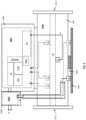
- the at least one vibration element 10 is - as in Fig. 2 indicated or from a synopsis of the Fig. 1 and 2 readily apparent - housed together with the at least one vibration exciter 41 and the at least two vibration sensors 51, 52 and possibly other components of the measuring sensor MW within a sensor housing 100 of the measuring system; this in particular in such a way that the at least one vibration element 10 is held on the transducer housing 100, for example rigidly connected to the transducer housing 100.
- the same sensor housing 100 has a wall made of a metal, for example stainless steel.
- the sensor housing 100 has a connecting piece for the electronics housing and the electronics housing 200 is mechanically connected to the connecting piece, possibly also releasably.
- the housing module 200A can be attached to the outside of the sensor housing 100, for example in such a way that the housing module 200A is on the outside of the sensor housing 100 and that the housing -Module 200B is attached to the outside of the housing module 200A.
- the vibration element 10 can also - as is usual with measuring sensors of the type in question or vibronic measuring systems formed with them - for example by means of one or more, in particular at least partially straight and / or at least partially circular arc-shaped, tubes with one of one, in particular metallic, Tube wall and a lumen covered by it, the tube or each of the tubes also being designed to guide the at least temporarily flowing fluid measuring material (or of the same measuring material to be flowed through) and to be allowed to vibrate accordingly.
- the vibration element can, for example, also be formed by means of one or more displacer elements placed within a lumen of a tube of the measuring sensor through which the measured substance flows, the displacer element or each of the displacer elements being set up to be flowed around by the measured substance and to be allowed to vibrate accordingly.
- the at least one vibration exciter 41 is in turn designed to convert electrical power fed there into forced mechanical vibrations of the at least one vibration element 11 causing mechanical power.
- the at least one vibration exciter 41 for example designed as an electrodynamic, electromagnetic or piezoelectric - as in Fig. 2 indicated and quite common in vibration-type measuring sensors or vibronic measuring systems formed with them - positioned so that a force generated thereby acts on the vibration element in the direction of an imaginary line of force running through a center of mass of the at least one vibration element, and / or that the vibration exciter 41 - like also in Fig. 2 shown - is the only vibration exciter that causes vibrations of the vibration element 10.
- the measuring system electronics ME of the measuring system according to the invention is also intended and set up accordingly to generate an - for example bipolar and / or at least temporarily periodic, possibly also harmonic - electrical driver signal e1 and thus to feed electrical power into the at least one vibration exciter 41, in such a way that the at least one vibration element 10 at least partially carries out useful vibrations, namely forced mechanical vibrations with a useful frequency f N , which are suitable for generating Coriolis forces in the flowing medium that are dependent on the mass flow but nevertheless act back on the vibration element 10, in such a way that the aforementioned useful vibrations Coriolis oscillations, namely mechanical oscillations with the useful frequency f N which are additionally forced by the Coriolis forces and are dependent on the mass flow m of the medium to be measured.
- useful vibrations namely forced mechanical vibrations with a useful frequency f N
- the driver signal e1 can accordingly, for example, be a harmonic electrical signal which forms the aforementioned signal component e1 N which determines the useful frequency f N or, for example, a multi-frequency electrical signal which is composed of several (spectral) signal components, but nevertheless contains a spectral useful component e1 N which determines the useful frequency f N be a signal.
- the useful vibrations excited by means of the vibration exciter 41 and the measuring system electronics ME connected to it can also, for example, be bending vibrations of the at least one Vibration element 10 is an associated rest position, the useful frequency f and/or a lowest instantaneous resonance frequency of the at least one vibration element 10 can be selected, namely set by means of the driver signal e1.
- the measuring system electronics ME can, for example, have a corresponding drive electronics Exc exhibit.
- the drive electronics Exc has a digital frequency output.
- the drive electronics Exc is also set up to output a frequency sequence at the same frequency output, namely a sequence of digital frequency values that quantify the signal frequency set for the driver signal e1, for example namely the currently set useful frequency (or the signal frequency of its signal component eN1).
- the measuring sensor MW is also equipped with electrodynamic vibration sensors 51, 52 in order to detect mechanical vibrations of the at least one vibration element 11, not least also forced mechanical vibrations of the at least one vibration element 11, the vibration sensor 51, for example, by means of a first Moving coil and the vibration sensor 52 can be formed, for example, by means of a second moving coil.
- the vibration sensor 51 is set up to convert vibration movements of the at least one vibration element 11 at a first measuring point into an electrical first vibration measurement signal s1 of the measuring sensor, such that - as in Fig.
- the same vibration measurement signal s1 has at least one (dependent on the time t) first useful component s1 N , namely an alternating voltage component with a frequency corresponding to the useful frequency f N
- the vibration sensor 52 is set up to detect vibration movements of the at least one vibration element at one of the first measuring points to convert the remote second measuring point into an electrical second vibration measurement signal s2 of the sensor, such that - as in Fig. 3 indicated - the same vibration measurement signal s2 has at least one second useful component s2 N (dependent on the time t), namely an alternating voltage component with a frequency corresponding to the useful frequency f N.
- each of the two vibration sensors 51, 52 is an electrodynamic vibration sensor
- the useful component s1 N accordingly has an amplitude U1 N which is dependent on the useful frequency f N and on a first magnetic flux ⁇ 1, namely a magnetic flux through the vibration sensor 51 (or dependent voltage level) and the useful component s2 N depends on the useful frequency f N and a second magnetic flux ⁇ 2, namely one magnetic flux through the vibration sensor 52 dependent amplitude U2 N (or dependent voltage level).
- Each of the two vibration sensors can, as is quite common with measuring sensors of the type in question, be formed, for example, by means of a moving coil.
- the first vibration sensor has a first permanent magnet, for example mechanically connected to the at least one vibration element to form the first measuring point, and a first permanent magnet, for example mechanically connected to the at least one vibration element 11 and / or to the sensor -Housing 100 has a first air coil connected and that the second vibration sensor has a second permanent magnet, for example mechanically connected to the at least one vibration element 11 to form the second measuring point, and a second permanent magnet, for example mechanically connected to the at least one vibration element and / or to the sensor - Housing 100 connected, second air coil.
- the vibration measurement signals s1, s2 generated by the measuring sensor 10 are subsequently fed to the measuring system electronics ME, for example via electrical connecting lines, in order to be processed accordingly, for example by means of digital signal processing (DSV), for example pre-amplified, filtered and digitized and then evaluated accordingly to become.
- DSV digital signal processing
- the vibration sensors 51, 52 are also arranged so that in the event of an excitation of the aforementioned Coriolis vibrations of the at least one vibration element 11, each of the useful components s1 N , s2 N of the vibration measurement signals s1 and s2 also each receive one of the mass flow m the phase angle that is dependent on the phase angle flowing through the measuring sensor 10 and can be measured, for example, relative to the driver signal e1 or its useful component e1 N ; this in particular in the way that, as in Fig.
- ⁇ 12 f(m)
- the vibration sensors 51, 52 can, like such measurement sensors, be quite common or even in Fig.
- the vibration sensor 51 is on the inlet side at least one Vibration element 11 or in its vicinity and the vibration sensor 52 are arranged on the outlet side of at least one vibration element 11 or in its vicinity.
- the two vibration sensors 51, 52 can also be the only vibration sensors useful for detecting vibrations of the at least one vibration element 11, such that the measuring sensor does not have any other vibration sensors apart from the same vibration sensors 51, 52.
- the measuring sensor has at least one temperature sensor 71 for detecting a temperature of the measuring sensor at a temperature measuring point, which is set up to generate a temperature measuring signal, namely a measuring signal representing the temperature at the temperature measuring point, in particular. with a temperature-dependent electrical voltage and/or a temperature-dependent electrical current.
- the measuring sensor can, for example, also have at least one strain sensor which is used to detect mechanical stresses within the measuring sensor.
- the measuring system electronics ME is, in addition to generating the driver signal e1, also intended or set up to receive and evaluate the vibration measurement signals s1, s2, namely based on the vibration measurement signals s1, s2, for example based on the aforementioned phase difference ⁇ 12 between the first and second useful components to determine mass flow measurement values representing the mass flow, for example also to output them in the form of analog values and / or in the form of digital values.
- the measuring system electronics 20 is also set up to first determine the phase difference ⁇ 12 based on the vibration measurement signals s1, s2.
- the measuring system electronics ME can also be set up to determine the respective predetermined phase angle of its respective useful component s1 N, s2 N from at least one of the applied vibration measurement signals s1 , s2, for example relative to the driver signal e1 or its pre-determined useful component e1 N , and /or to determine the useful frequency f N based on at least one of the vibration measurement signals s1, s2, for example also during operation at least one phase sequence, namely a sequence of digital phase values corresponding to quantifying the phase angle of one of the first and second useful components and/or a frequency sequence, namely a sequence to generate digital frequency values quantifying the useful frequency f N , such that the phase sequence corresponds to a time profile of the phase angle of the corresponding useful component or the frequency sequence corresponds to a time profile of the useful frequency.
- phase angles or the generation of the aforementioned phase sequence can, for example, as is quite common with Coriolis mass flow measuring devices, by means of a quadrature demodulation (Q/I demodulation) of the respective vibration measurement signal, which is carried out accordingly in the measuring system electronics ME, with a signal having the useful frequency first harmonic reference signal (Q) and a second harmonic reference signal (I) which is 90 ° out of phase with it.
- Q/I demodulation quadrature demodulation of the respective vibration measurement signal
- the useful vibrations caused by means of driver signal e1 are resonance vibrations of the at least one vibration element 11
- the useful frequency f N of the vibration measurement signals s1, s2 can serve as a measure for the density and/or the viscosity of the medium to be measured and can accordingly be determined by means of the Measuring system electronics ME the density and / or the viscosity are determined based on the aforementioned frequency sequence.
- the measuring system electronics 20 is also set up according to a further embodiment of the invention to receive the temperature measurement signal generated by the temperature sensor or the strain measurement signal generated by the strain sensor to receive and process, in particular to digitize and evaluate; this, for example, in such a way that the measuring system electronics ME determines a temperature of the displacement element and/or a temperature of the medium to be measured based on the at least one temperature measurement signal.
- the measuring system electronics ME can also have corresponding measuring and control electronics DSV, which, as in Fig. 2 shown schematically, is electrically connected to the measuring sensor 10 or its vibration sensors 51, 52, for example in such a way that from the measuring and control electronics DSV a first measuring signal input of the measuring system electronics ME for the vibration measuring signal s1 and at least a second measuring signal input of the measuring system electronics 20 are formed for the vibration measurement signal s2.
- the measuring and control electronics DSV can advantageously be set up to digitally process the supplied vibration measurement signals s1, s2, and possibly also the temperature and/or strain measurement signals, for example by means of at least one microprocessor and/or at least one digital signal processor (DSP) and/or be formed by means of a programmable logic component (FPGA) and/or by means of a customer-specific programmed logic component (ASIC).
- DSP digital signal processor
- FPGA programmable logic component
- ASIC customer-specific programmed logic component
- the program codes executed during operation of the measuring system in one or more of the aforementioned microprocessors or digital signal processors of the measuring system electronics ME can each be stored persistently, for example, in one or more non-volatile data memories (EEPROM) of the measuring system electronics ME and when starting the same be loaded into a volatile data memory (RAM) provided in the measuring system electronics ME or the measuring and control electronics DSV, for example integrated in the microprocessor.
- EEPROM non-volatile data memories
- RAM volatile data memory
- the vibration measurement signals s1, s2 must of course first be converted into corresponding digital signals for processing in the microprocessor or in the digital signal processor using appropriate analog-to-digital converters (A/D), for example by digitizing the respective signal voltage of the vibration measurement signals s1, s2 , see for example those mentioned at the beginning US-B 63 11 136 or US-A 2011/0271756 .
- A/D analog-to-digital converters
- Volatile electronic data memory EEPROM is provided, which is set up to hold digital data, for example even without an applied operating voltage.
- the aforementioned phase sequence and/or the aforementioned frequency sequence can also be generated, for example also output at a corresponding digital phase output or at a corresponding digital frequency output and thus for further processing in the measuring system electronics ME to be provided.
- the measuring system electronics ME is formed by means of the aforementioned drive electronics Exc and by means of the aforementioned measuring and control electronics DSV, its phase output can be connected to a phase input provided in the drive electronics Exc, for example also a component of the aforementioned
- phase comparator forming a phase locked loop can be electrically connected and the same phase comparator can also be set up to determine a phase difference between the aforementioned signal component e1 N of the driver signal e1 and at least one of the useful components s1 N , s2 N based on the phase sequence and/or an extent thereof Determine phase difference.
- the measuring and control electronics DSV is also set up to generate the aforementioned first and second useful component sequences and to output at least one of the useful component sequences to a digital amplitude output.
- the aforementioned amplitude output of the measuring and control electronics DSV can also be electrically connected, for example, to an amplitude input of the drive electronics Exc which detects an amplitude of the oscillations of the at least one vibration element 11, and the drive electronics Exc can also be set up to generate the driver signal e1 based on the amplitude sequence to generate that the vibrations of the at least one vibration element or its useful vibrations reach a predetermined vibration amplitude or do not permanently exceed or fall below it.
- the useful components of the two vibration measurement signals s1, s2 or their amplitudes due to the operating principle of the two electrodynamic vibration sensors, depend on the temporal change in the respective magnetic flux within the vibration sensor, in the case of a moving coil as a vibration sensor, namely the linking or .Induction flux within the respective air coil, depending;
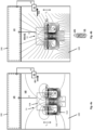
- the causes of such an external magnetic field H1 can be, for example, an electric field generated in the vicinity of the respective measuring system, for example due to electric motors, transformers, inverters or high electrical (System components carrying direct currents, such as busbars, and/or can - as in Fig. 4b indicated - a magnet positioned outside the respective measuring system or in its vicinity, for example an electromagnet or a permanent magnet.
- Such an undesirable influence on the first and/or second useful component s1 N , s2 N or impairment of the functionality of the measurement sensor by an external magnetic field H1 can also consist, for example, in the fact that - as in Fig. 3 indicated - at least one of the useful components contains an additional interference component of the same frequency (S1 N,Err , S2 N,Err ), such that the aforementioned phase angle of the same useful component, and therefore also the aforementioned phase difference ⁇ 12 ( ⁇ 12 -> ⁇ 12 Err ), then produces a phase error, namely has a portion dependent on the external magnetic field H1 or its influence on the magnetic flux ultimately established in the respective vibration sensor; this, for example, in such a way that the integrity of at least one of the vibration measurement signals or the mass flow measurement values is unacceptably reduced or that the same phase error leads to a measurement accuracy with which the measuring system electronics 20 then determines the mass flow measurement values from a tolerance range specified for the measuring system .
- the magnetic field detector 61 is positioned in particular outside the sensor housing 100; This is particularly the case in such a way that the magnetic field detector 61 is also positioned outside the aforementioned electronics housing 200.
- the magnetic field detector 61 can, for example, be attached to the outside of the sensor housing 100, in particular also be fixed directly on the sensor housing. According to a further embodiment of the invention, it is further provided that the magnetic field detector 61 is positioned in the vicinity of the vibration sensor 51, for example less than 5 cm away from it.
- the magnetic field detector 61 is in particular set up to convert changes in the magnetic field H0 + H1 at a third measuring point formed by the magnetic field detector 61 and distant from both the aforementioned first measuring point and the aforementioned second measuring point into a, for example, electrical, first magnetic field signal ⁇ 1, which is a has an amplitude U3 which is dependent on a third magnetic flux ⁇ 3 - established here both outside the vibration sensor 51 and outside the vibration sensor 52, namely a magnetic flux through the magnetic field detector 61 and/or on a surface density B3 of the same magnetic flux ⁇ 3; this in particular in such a way that the magnetic field signal ⁇ 1 follows at least one change in the magnetic flux ⁇ 3 and/or its surface density B3 with a change in the amplitude U3.
- the magnetic field detector 61 can be formed, for example, by means of at least one Hall sensor and/or by means of at least one reed switch.
- the magnetic field detector is also electrically connected to the measuring system electronics 20 via connecting lines that run along the outside of the sensor housing.
- the same connecting lines can also be provided, for example, by means of a connecting cable and / or laid at least in sections within a protective tube or protective tube attached to the outside of the sensor and / or electronics housing.
- the measuring system electronics 20 is also set up to use the magnetic field signal ⁇ 1 to at least qualitatively determine whether the aforementioned external magnetic field H1 is also established within the measuring sensor - in addition to the aforementioned internal magnetic field H0 - for example to determine, whether there is a fault in the sensor due to the same external magnetic field H1, in particular reducing the functionality of the measuring sensor and/or causing a malfunction of the measuring sensor as a whole and/or reducing the integrity of at least one of the first and second vibration measurement signals or the mass flow measured values.
- the magnetic field signal ⁇ 1 can, for example, be a signal that only evaluates the aforementioned magnetic field H0 + H1 or its changes qualitatively or only assumes discrete values to a limited extent, for example a signal that nominally only has two Binary switching signal having states.
- the magnetic field signal ⁇ 1 can, for example, also be an analog signal that continuously quantifies the magnetic field H0 + H1 or its changes in value and time, for example an analog electrical signal with an electrical voltage that is dependent on the magnetic flux ⁇ 3 and/or its surface density B3.
- the measuring system electronics 20 is also set up, according to a further embodiment of the invention, to at least occasionally use the at least one magnetic field signal to determine one or more key figure values for at least one - for example, to calculate an influence on the measuring sensor by the external magnetic field and/or an influence on at least one of the magnetic fluxes ⁇ 1, ⁇ 2 - magnetic field index MK1, such that the same magnetic field index MK1; this in particular in such a way that the same magnetic field characteristic MK1 is dependent on a deviation of the magnetic flux ⁇ 1 from the magnetic flux ⁇ 2 and/or the same deviation is evaluated and/or quantified; alternatively the same
- the magnetic field characteristic MK1 can be determined repeatedly during operation of the Coriolis mass flow measuring device using the measuring system electronics ME, for example using digital amplitude values determined for the amplitude U3 of the magnetic field signal ⁇ 1.
- the measuring system electronics ME can also be set up to store one or more of the aforementioned digital amplitude values for the amplitude U3 in the same data memory EEPROM to store, for example together with a numerical value for a time variable (time stamp) corresponding to a respective point in time when the respective key figure value was determined.
- the measuring system electronics 20 is further set up according to a further embodiment of the invention to evaluate one or more key figure values for the at least one magnetic field key figure MK1, for example namely each with one or more previously determined for the same magnetic field characteristic MK1, for example not in the aforementioned to compare reference values BK1 1 (BK1 1 , BK1 2 ,... BK1 i ...) stored in the volatile electronic data memory EEPROM.
- the measuring system electronics ME is also set up to determine whether one or more key figure values for the magnetic field key figure MK1 are greater than one or more such reference values for the magnetic field key figure MK1, for example namely representing a measuring system that is no longer intact and if necessary, for example, also to issue a (fault) message signaling this, for example to display it on site and / or to transmit it as a status message to the aforementioned electronic data processing system.
- the aforementioned reference values for the magnetic field characteristic MK1 can be, for example, a reduced functionality of the measuring sensor (attributable to an external magnetic field) or a reference value representing a malfunction of the measuring sensor (attributable to an external magnetic field).
- reference values can, for example, be determined in advance, for example by the manufacturer of the measuring system or during a (factory) calibration carried out during the production of the measuring system and/or during commissioning on site, and/or during operation of the measuring system; this, for example, in such a way that the respective magnetic field index MK1 is first determined for the completed, therefore intact measuring system and is converted into the reference value BK1 1 using a tolerance value corresponding to a still tolerable influence and/or by the magnetic field index MK1 using the in The measurement system is determined directly in the vicinity of a magnet that creates a reference magnetic field but is otherwise intact and is stored as a reference value BK1 1 in the data memory EEPROM.
- the determination of the key figure values MK1 or the determination of the presence of an external magnetic field can, for example, be initiated or suspended again automatically, for example in a time-controlled manner and/or depending on changes in other diagnostic values.
- the determination of the key figure values can also be initiated and/or suspended externally to the measuring system, for example starting from the aforementioned electronic data processing system via the aforementioned transmitting and receiving electronics COM and/or starting from operating personnel on site via the aforementioned display. and HMI control element.
- the measuring system electronics 20 is set up to receive and evaluate a start command which initiates at least the determination of the key figure values for at least the magnetic field key figure MK1, possibly also its aforementioned evaluation, namely an input of the start command to detect and then initiate a determination of the key figure values for the first magnetic field key figure MK1 and / or the measuring system electronics is set up to receive and evaluate a stop command that at least temporarily prevents the determination of the key figure values for the magnetic field key figure MK1 , namely to detect an input of the stop command and then at least temporarily stop a determination of the key figure values for the first magnetic field key figure MK1.
- the electronics module ME1 can, for example, be set up to both generate the aforementioned driver signal e1 and to receive and evaluate the vibration measurement signals s1, s2
- the electronic module ME2 can, for example, be set up to receive and evaluate the magnetic field signal ⁇ 1, for example to calculate the aforementioned magnetic field characteristic number MK1 and/or to compare it with the aforementioned reference values BK1 1 and/or to calculate the aforementioned (disturbance) )generate message.
- a signal output of the electronics module ME2 can be electrically connected to a corresponding signal input of the electronics module ME1 and the electronics module ME2 can be set up to transmit the aforementioned (fault) message to the electronics module ME1.
- the electronics module ME2 can be set up to receive measured values determined by the electronics module ME1 and output them accordingly at a signal output, for example in such a way that no measured values, in particular no mass flow measured values, are output in the event of a malfunction is present due to the external magnetic field H1, or that mass flow measurement values are only output as qualified measurement values of the measuring system if there is no such disturbance.
- the measuring system electronics 20 is also set up to monitor the functionality of the magnetic field detector 61 itself, for example by evaluating the magnetic field signal ⁇ 1; this in particular in such a way that the measuring system electronics ME checks based on the magnetic field signal ⁇ 1 and / or based on a measurement of an electrical resistance and / or an electrical impedance of the connecting lines electrically connecting the magnetic field detector 61 and the measuring system electronics ME whether magnetic field detector 61 and Measuring system electronics ME are still electrically connected to each other.
- the measuring system comprises a protective shield made, for example, of stainless steel, approximately 1.4404 (St 316L). 300 for the at least one magnetic field detector.
- protective shield 300 is, as in Fig. 2 shown schematically, positioned outside the pickup housing 100 to form a gap 300* located between the protective shield and the pickup housing 100 and suitable for accommodating at least the magnetic field detector 61, and the magnetic field detector 61 is then positioned within the gap.
- the protective shield 300 can, for example, be attached to the outside of the sensor housing 100, for example connected to it in a materially bonded manner, in particular welded to it.
- the protective shield 300 can also be releasably connected to the sensor housing 100, for example screwed to it and/or strapped onto the sensor housing 100. Alternatively or in addition can the protective shield 300 can also be attached to the aforementioned electronics housing 200.
- the protective shield 300 can also be set up or designed, for example, to shield the measuring sensor or both the measuring sensor MW and the magnetic field detector against the external magnetic field H1.
- the protective shield 300 can also consist at least partially of a ferromagnetic material, for example a ferritic steel.
- the protective shield is releasably connected to the transducer housing 100 and/or the electronics housing 200
- the protective shield 300 is attached to the transducer housing or on the transducer housing by means of at least one seal Electronics housing secured, for example against unauthorized removal.
- a further embodiment of the invention provides that the measuring system for detecting the magnetic field - as in Fig. 2 . or 5a and 5b each indicated or also readily apparent from their synopsis - at least one second magnetic field detector 62, for example also of the same construction as the magnetic field detector 61, which is set up to detect changes in the magnetic field H0 or H0+H1 on one of the aforementioned third
- the fourth measuring point away from the measuring point for example also from the first measuring point and / or from the second measuring point, into a second magnetic field signal ⁇ 2, in particular, which evaluates the same changes in the magnetic field and / or quantifies the changes and / or electrical, the one of a fourth magnetic flux ⁇ 4, namely a magnetic flux through the magnetic field detector 62 and / or an amplitude U4 dependent on a surface density B4 of the same magnetic flux ⁇ 4, such that the magnetic field signal ⁇ 2 is based on at least a
- the measuring system electronics 20 is also set up to receive and evaluate the magnetic field signal ⁇ 2, namely to use the magnetic field signal ⁇ 2 to determine whether the external magnetic field H1 is present.
- the magnetic field signal ⁇ 2 can also be designed as an analog signal, for example with an electrical voltage that depends on the magnetic flux ⁇ 4 and/or its surface density B4.
- the magnetic field detector 62 can be formed by means of a Hall sensor and/or a reed switch. According to a further embodiment of the invention, it is also provided that the magnetic field detector 62 is positioned outside the sensor housing 100, for example, is attached to the outside of the sensor housing 100.
- the magnetic field detector 62 can be positioned, for example, in the vicinity of the vibration sensor 52, in particular less than 5 cm and/or less far away from the vibration sensor 52 than from the vibration sensor 51. Alternatively or in addition, the magnetic field detector 62 can, for example, also be positioned less far away from the vibration sensor 51 than from the vibration sensor 52. For the aforementioned case that the measuring system has a protective shield, the magnetic field detector 62 can, for example, also be positioned next to the magnetic field detector 61 in the gap.
- the measuring system can also have further magnetic field detectors, for example in such a way that magnetic field detectors are located both on the front and back of the transducer housing and/or on both the left and right sides of the transducer housing/or on both the top and bottom of the transducer -Housing are positioned or in such a way that at least one magnetic field detector, for example two or more and / or the same number of magnetic field detectors, are arranged on at least two opposite sides of the measuring sensor or its sensor housing.
Landscapes
- Physics & Mathematics (AREA)
- General Physics & Mathematics (AREA)
- Fluid Mechanics (AREA)
- Condensed Matter Physics & Semiconductors (AREA)
- Engineering & Computer Science (AREA)
- Signal Processing (AREA)
- Measuring Volume Flow (AREA)
Claims (18)
- Système de mesure vibronique, notamment un débitmètre massique Coriolis ou un débitmètre massique/densimètre Coriolis, lequel système est destiné à mesurer un débit massique d'un produit fluide - notamment d'un gaz, d'un liquide ou d'une dispersion -, lequel système de mesure comprend :- un transducteur (MW),-- lequel transducteur présente au moins un élément vibrant (10), notamment tubulaire, au moins un excitateur de vibrations destiné à exciter et maintenir des vibrations mécaniques de l'au moins un élément vibrant (11), ainsi qu'un premier capteur de vibrations électrodynamique (51) et au moins un deuxième capteur de vibrations électrodynamique (52), notamment de construction identique au premier capteur de vibrations (51), lesquels capteurs sont destinés à détecter des vibrations mécaniques de l'au moins un élément vibrant, notamment ses vibrations utiles, et-- lequel transducteur est conçu pour guider le produit, notamment pour être traversé au moins temporairement par le produit ;- un boîtier de transmetteur (100) pour loger le transmetteur, lequel boîtier est notamment doté d'une paroi métallique ;- au moins un premier détecteur de champ magnétique (61) formé notamment au moyen d'un capteur à effet Hall et/ou d'un interrupteur à lames souples, lequel détecteur est destiné à détecter un champ magnétique (H0+H1) établi à l'intérieur du système de mesure, notamment provoqué par un champ électrique généré à l'extérieur du boîtier de transducteur et/ou par un aimant positionné à l'extérieur du boîtier de transducteur et/ou constant dans le temps ;- ainsi qu'une électronique de système de mesure (ME) couplée électriquement aussi bien au transducteur - à savoir à son au moins un excitateur de vibrations et à ses premier et deuxième capteurs de vibrations - qu'au premier détecteur de champ magnétique (61), laquelle électronique est notamment formée et/ou conçue de façon modulaire au moyen d'au moins un microprocesseur ;- le transducteur étant positionné à l'intérieur du boîtier de transducteur (100) et le premier détecteur de champ magnétique étant positionné à l'extérieur du boîtier de transducteur (100), notamment de telle sorte que l'au moins un élément vibrant (11) est maintenu sur le boîtier de transducteur (100) et/ou que le premier détecteur de champ magnétique est monté à l'extérieur du boîtier de transducteur (100) ;- l'au moins un élément vibrant étant conçu pour être mis en contact avec le produit qui s'écoule et pour être laissé vibrer pendant ce temps ;- l'au moins un excitateur de vibrations étant conçu pour convertir l'énergie électrique qui lui est fournie en une énergie mécanique provoquant des vibrations mécaniques forcées de l'élément vibrant ;- l'électronique de système de mesure étant conçue pour générer un signal d'attaque électrique (e1) et pour alimenter ainsi en énergie électrique l'au moins un excitateur de vibrations, de telle sorte que l'élément vibrant exécute au moins en partie des vibrations utiles, à savoir des vibrations mécaniques forcées avec au moins une fréquence utile, à savoir une fréquence de vibration prédéfinie par le signal d'attaque électrique, laquelle fréquence correspond notamment à une fréquence de résonance du transducteur, lesquelles vibrations sont appropriées pour provoquer dans le produit en écoulement des forces de Coriolis dépendant du débit massique ;- le premier capteur de vibrations (51) étant conçu pour convertir les mouvements vibratoires de l'au moins un élément vibrant au niveau d'un premier point de mesure, en un premier signal électrique de mesure de vibration (s1) du transducteur, de telle sorte que ledit premier signal de mesure de vibration comprenne au moins une première composante utile (s1N1), à savoir une composante de tension alternative-- avec une fréquence correspondant à la fréquence utile,-- et avec une amplitude (U1N) dépendant de la fréquence utile et d'un premier flux magnétique (Φ1), à savoir un flux magnétique à travers le premier capteur de vibrations (51) ;- le deuxième capteur de vibrations (52) étant conçu pour convertir les mouvements vibratoires de l'au moins un élément vibrant au niveau d'un deuxième point de mesure distant du premier point de mesure, en un deuxième signal électrique de mesure de vibration (s2) du transducteur, de telle sorte que ledit deuxième signal de mesure de vibration comprenne au moins une deuxième composante utile (s2N1), à savoir une composante de tension alternative-- avec une fréquence correspondant à la fréquence utile,-- et avec une amplitude (U2N) dépendant de la fréquence utile et d'un deuxième flux magnétique (Φ2), à savoir un flux magnétique à travers le deuxième capteur de vibrations (52) ;- le premier détecteur de champ magnétique (61) étant conçu pour détecter le champ magnétique (H1) au niveau d'un troisième point de mesure situé à l'extérieur du boîtier de transducteur (100) et pour le convertir en un premier signal de champ magnétique (φ1), lequel signal évalue et/ou quantifie le même champ magnétique (H1) et/ou est électrique, lequel signal présente une amplitude qui dépend d'un troisième flux magnétique (Φ3), à savoir un flux magnétique à travers le premier détecteur de champ magnétique et/ou une densité de surface (B3) du flux magnétique (Φ3) en question, notamment de telle sorte que le premier signal de champ magnétique suit au moins une modification du troisième flux magnétique (Φ3) et/ou de sa densité de surface (B3) avec une modification de l'amplitude (U3) ;- et l'électronique de système de mesure (20) étant conçue pour recevoir et évaluer aussi bien les premiers et deuxièmes signaux de mesure de vibration qu'au moins le premier signal de champ magnétique (φ1), à savoir-- pour déterminer, à l'aide des premiers et des deuxièmes signaux de mesure de vibration, des valeurs mesurées de débit massique, notamment numériques, représentant le débit massique, notamment pour délivrer lesdits signaux à une sortie de signal,-- ainsi que pour déterminer, à l'aide du premier signal de champ magnétique, au moins qualitativement, si et/ou dans quelle mesure le champ magnétique (H1) est établi aux premiers et/ou aux deuxièmes points de mesure ou apporte une contribution aux premiers et/ou aux deuxièmes flux magnétiques (Φ1, Φ2), et/ou pour déterminer si une perturbation - notamment une diminution de la capacité de fonctionnement du système de mesure et/ou un dysfonctionnement du système de mesure et/ou une dégradation de l'intégrité d'au moins l'un des premiers et des deuxièmes signaux de mesure de vibration ou des valeurs mesurées de débit massique obtenues à partir desdits signaux - du système de mesure par ledit champ magnétique (H1) est présente.
- Système de mesure vibronique selon la revendication 1, comprenant en outre au moins un boîtier électronique (200), notamment de construction modulaire, l'électronique du système de mesure étant logée au moins partiellement, notamment complètement, à l'intérieur du boîtier électronique (200) et/ou le premier détecteur de champ magnétique étant positionné à l'extérieur du boîtier électronique (200).
- Système de mesure vibronique selon la revendication précédente, pour lequel le boîtier de transmetteur (100) présente une tubulure de raccordement pour le boîtier électronique (200), le boîtier électronique (200) étant relié mécaniquement à la tubulure de raccordement, notamment de manière amovible.
- Système de mesure vibronique selon l'une des revendications précédentes, comprenant en outre : un écran de protection, notamment métallique, pour l'au moins un détecteur de champ magnétique, l'écran de protection étant positionné à l'extérieur du boîtier de transmetteur en formant un espace intermédiaire situé entre l'écran de protection et le boîtier de transmetteur, notamment monté à l'extérieur du boîtier de transmetteur, et le détecteur de champ magnétique étant positionné à l'intérieur du même espace intermédiaire.
- Système de mesure vibronique selon la revendication précédente,- pour lequel l'écran de protection est constitué au moins partiellement d'un acier inoxydable ; et/ou- pour lequel l'écran de protection est relié au boîtier de transmetteur par une liaison de matière, notamment soudé à celui-ci ; et/ou- pour lequel l'écran de protection est fixé au boîtier de transmetteur au moyen d'au moins un plombage.
- Système de mesure vibronique selon l'une des revendications 2 à 5, pour lequel le boîtier électronique (200) est conçu de manière modulaire, de telle sorte que le boîtier électronique (200) comporte un premier module de boîtier (200A) et un deuxième module de boîtier (200B), notamment de telle sorte que le premier module de boîtier (200A) est monté à l'extérieur du boîtier de transmetteur (100) et/ou que le deuxième module de boîtier (200B) est monté à l'extérieur du premier module de boîtier (200A).
- Système de mesure vibronique selon l'une des revendications précédentes, pour lequel l'électronique de système de mesure est conçue de manière modulaire, de telle sorte que l'électronique de système de mesure présente un premier module électronique (ME1) et un deuxième module électronique (ME2).
- Système de mesure vibronique selon la revendication 6 et 7,- pour lequel le premier module de boîtier (200A) du boîtier électronique (200) est conçu pour recevoir le premier module électronique (ME1) de l'électronique de système de mesure (ME), et le deuxième module de boîtier (200B) du boîtier électronique (200) est conçu pour recevoir le deuxième module électronique (ME2) de l'électronique de système de mesure (ME) ;- et pour lequel le premier module électronique (ME1) est logé à l'intérieur du premier module de boîtier (200A) et le deuxième module électronique (ME2) est logé à l'intérieur du deuxième module de boîtier (200B).
- Système de mesure vibronique selon la revendication 7 ou 8,- pour lequel le premier module électronique (ME1) de l'électronique du système de mesure est conçu pour générer le signal d'attaque ainsi que pour recevoir et évaluer les premier et deuxième signaux de mesure des vibrations, et
pour lequel le deuxième module électronique (ME2) de l'électronique du système de mesure est conçu pour recevoir et évaluer le premier signal de champ magnétique ; et/ou- les premier et deuxième modules électroniques (ME1, ME2) de l'électronique du système de mesure étant couplés électriquement entre eux, notamment de telle sorte qu'une sortie de signal du premier module électronique (ME1) est reliée électriquement à une entrée de signal du deuxième module électronique (ME2). - Système de mesure vibronique selon l'une des revendications précédentes, pour lequel le premier signal de champ magnétique (φ1) est un signal analogique, notamment à valeur et à temps continus, notamment avec une tension dépendant du troisième flux magnétique (Φ3) et/ou de sa densité de surface (B3).
- Système de mesure vibronique selon la revendication précédente, pour lequel l'électronique de système de mesure est conçue pour calculer, à l'aide du premier signal de champ magnétique, des valeurs caractéristiques pour au moins un indice de champ magnétique (MK1), lesquelles valeurs caractérisent notamment une influence du capteur par le champ magnétique externe et/ou une influence d'au moins l'un des premier et deuxième flux magnétiques, notamment de telle sorte que ledit indice de champ magnétique dépend d'un écart du premier flux magnétique par rapport au deuxième flux magnétique et/ou évalue et/ou quantifie ledit écart ou que ledit indice de champ magnétique dépend d'un écart du premier flux magnétique par rapport à une valeur de référence déterminée au préalable et/ou évalue et/ou quantifie ledit écart.
- Système de mesure vibronique selon l'une des revendications précédentes,- pour lequel l'électronique de système de mesure comprend une mémoire de données électronique non volatile (EEPROM), laquelle est conçue pour conserver des données numériques, notamment même sans tension de service appliquée, à savoir pour enregistrer une ou plusieurs valeurs de référence déterminées au préalable pour l'indice de champ magnétique ;- et pour lequel une ou plusieurs valeurs de référence pour l'indice de champ magnétique, notamment déterminées au préalable par le fabricant du système de mesure et/ou lors de la fabrication du système de mesure et/ou pendant le fonctionnement du système de mesure, notamment une ou plusieurs valeurs de référence représentant une capacité de fonctionnement réduite du capteur et/ou notamment une ou plusieurs valeurs de référence représentant un dysfonctionnement du capteur, sont mémorisées dans la mémoire de données électronique.
- Système de mesure vibronique selon la revendication précédente, pour lequel l'électronique du système de mesure est conçue pour comparer une ou plusieurs valeurs caractéristiques pour l'indice de champ magnétique respectivement avec une ou plusieurs valeurs de référence pour l'indice de champ magnétique stockées dans la mémoire de données.
- Système de mesure vibronique selon l'une des revendications précédentes, pour lequel le premier détecteur de champ magnétique est positionné moins loin du premier capteur de vibrations (51) que du deuxième capteur de vibrations (52) et/ou à moins de 5 cm du premier capteur de vibrations (51).
- Système de mesure vibronique selon l'une des revendications précédentes, comprenant en outre : pour la détection du champ magnétique (H1), au moins un deuxième détecteur de champ magnétique (62), formé notamment au moyen d'un capteur à effet Hall et/ou d'un interrupteur à lames souples et/ou de construction identique au premier détecteur de champ magnétique (61),- le deuxième détecteur de champ magnétique (62) étant conçu pour détecter le champ magnétique (H1) au niveau d'un quatrième point de mesure éloigné du troisième point de mesure, notamment également éloigné du premier point de mesure et/ou du deuxième point de mesure et/ou situé à l'extérieur du boîtier de transmetteur (100), et pour le convertir en un deuxième signal de champ magnétique (φ2), notamment évaluant le champ magnétique (H1) et/ou quantifiant le champ magnétique (H1) et/ou électrique, lequel signal présente une amplitude (U4) dépendant d'un quatrième flux magnétique (Φ4), notamment un flux magnétique à travers le deuxième détecteur de champ magnétique et/ou dépendant d'une densité de surface (B4) dudit flux magnétique (Φ4), notamment de telle sorte que le deuxième signal de champ magnétique (φ2) suit au moins une modification du quatrième flux magnétique (Φ4) et/ou de sa densité de surface (B4) avec une modification de l'amplitude (U4) ;- et l'électronique de système de mesure étant conçue pour recevoir et évaluer également le deuxième signal de champ magnétique (φ2), à savoir déterminer à l'aide du deuxième signal de champ magnétique si le champ magnétique externe (H1) est présent.
- Système de mesure vibronique selon l'une des revendications précédentes,- pour lequel chacune des première et deuxième composantes utiles présente respectivement un angle de phase dépendant du débit massique ;- et pour lequel l'électronique du système de mesure est conçue pour calculer les valeurs mesurées de débit massique à l'aide d'une différence de phase entre les première et deuxième composantes utiles, à savoir une différence entre l'angle de phase de la première composante utile et l'angle de phase de la deuxième composante utile.
- Système de mesure vibronique selon l'une des revendications précédentes, pour lequel l'au moins un élément vibrant est formé au moyen d'au moins un tube, notamment au moins partiellement droit et/ou au moins partiellement en forme d'arc de cercle, avec un canal intérieur enveloppé par une paroi de tube, notamment métallique, et un canal intérieur enveloppé par ladite paroi, et lequel élément est conçu pour être traversé par un produit et être laissé vibrer pendant ce temps.
- Utilisation d'un système de mesure vibronique selon l'une des revendications précédentes, lequel système est destiné à la mesure d'un débit massique d'un produit fluide, notamment d'un gaz, d'un liquide ou d'une dispersion, s'écoulant dans une conduite.
Applications Claiming Priority (2)
| Application Number | Priority Date | Filing Date | Title |
|---|---|---|---|
| DE102019133610.4A DE102019133610A1 (de) | 2019-12-09 | 2019-12-09 | Vibronisches Meßsystem zum Messen eines Massestroms eines fluiden Meßstoff |
| PCT/EP2020/082907 WO2021115761A1 (fr) | 2019-12-09 | 2020-11-20 | Système de mesure vibronique destiné à mesurer un débit massique d'un milieu de mesure fluide |
Publications (2)
| Publication Number | Publication Date |
|---|---|
| EP4073475A1 EP4073475A1 (fr) | 2022-10-19 |
| EP4073475B1 true EP4073475B1 (fr) | 2023-11-15 |
Family
ID=73543277
Family Applications (1)
| Application Number | Title | Priority Date | Filing Date |
|---|---|---|---|
| EP20811305.0A Active EP4073475B1 (fr) | 2019-12-09 | 2020-11-20 | Système de mesure vibronique destiné à mesurer un débit massique d'un milieu de mesure fluide et utilisation du système de mesure vibronique |
Country Status (5)
| Country | Link |
|---|---|
| US (1) | US12281924B2 (fr) |
| EP (1) | EP4073475B1 (fr) |
| CN (1) | CN114761763B (fr) |
| DE (1) | DE102019133610A1 (fr) |
| WO (1) | WO2021115761A1 (fr) |
Families Citing this family (6)
| Publication number | Priority date | Publication date | Assignee | Title |
|---|---|---|---|---|
| DE102020133566A1 (de) | 2020-12-15 | 2022-06-15 | Endress+Hauser Flowtec Ag | Modulares Coriolis-Durchflussmessgerät |
| DE102021113360A1 (de) * | 2021-05-21 | 2022-11-24 | Endress + Hauser Flowtec Ag | Vibronisches Meßsystem |
| EP4430366A1 (fr) * | 2021-11-12 | 2024-09-18 | Micro Motion, Inc. | Appareil et procédé de quantification de champ magnétique externe de débitmètre de coriolis |
| CN119325550A (zh) * | 2022-06-07 | 2025-01-17 | 高准有限公司 | 具有针对外部磁场的补偿的科里奥利流量计 |
| DE102023110589A1 (de) * | 2023-04-25 | 2024-10-31 | Endress+Hauser Flowtec Ag | Feldgerät der Automatisierungstechnik |
| CN118990547B (zh) * | 2024-09-20 | 2025-03-18 | 国网江苏省电力有限公司常州供电分公司 | 变电站机器人智能巡检方法 |
Family Cites Families (108)
| Publication number | Priority date | Publication date | Assignee | Title |
|---|---|---|---|---|
| US4491009A (en) | 1983-06-10 | 1985-01-01 | Micro Motion, Inc. | Electronic circuit for vibrating tube densimeter |
| WO1985005677A1 (fr) | 1984-06-04 | 1985-12-19 | Exac Corporation | Appareil de mesure de la densite et de la vitesse de debit-masse |
| US4756198A (en) | 1986-01-24 | 1988-07-12 | Exac Corporation | Sensor apparatus for mass flow rate measurement system |
| DE8712331U1 (de) | 1986-09-26 | 1988-01-28 | Flowtec AG, Reinach, Basel | Corioliskraft-Massendurchflussmesser |
| WO1988002853A1 (fr) | 1986-10-09 | 1988-04-21 | Micro Motion, Inc. | Appareil et procedes de mesure de la densite d'un fluide inconnu en utilisant un debitmetre de coriolis |
| US4777833A (en) | 1986-11-12 | 1988-10-18 | Micro Motion, Inc. | Ferromagnetic drive and velocity sensors for a coriolis mass flow rate meter |
| ATE85116T1 (de) | 1987-07-15 | 1993-02-15 | Micro Motion Inc | Massendurchflussmesser mit einer kompensation der asymmetrie und einer zaehfluessigen daempfung. |
| US4876898A (en) | 1988-10-13 | 1989-10-31 | Micro Motion, Inc. | High temperature coriolis mass flow rate meter |
| US4996871A (en) | 1989-06-02 | 1991-03-05 | Micro Motion, Inc. | Coriolis densimeter having substantially increased noise immunity |
| US5009109A (en) | 1989-12-06 | 1991-04-23 | Micro Motion, Inc. | Flow tube drive circuit having a bursty output for use in a coriolis meter |
| US5373745A (en) | 1991-02-05 | 1994-12-20 | Direct Measurement Corporation | Single path radial mode Coriolis mass flow rate meter |
| US5497665A (en) | 1991-02-05 | 1996-03-12 | Direct Measurement Corporation | Coriolis mass flow rate meter having adjustable pressure and density sensitivity |
| EP0518124B1 (fr) | 1991-06-09 | 1995-09-06 | Krohne AG | Débitmètre massique Coriolis |
| US5295084A (en) | 1991-10-08 | 1994-03-15 | Micromotion, Inc. | Vibrating tube densimeter |
| EP0547455B1 (fr) | 1991-12-19 | 1996-09-18 | Krohne AG | Débitmètre de masse |
| US5379649A (en) * | 1991-12-23 | 1995-01-10 | Micro Motion, Inc. | Coriolis effect meter using optical fiber sensors |
| ES2064132T3 (es) | 1992-04-09 | 1995-01-16 | Flowtec Ag | Disposicion de un cuerpo vibrador para un aparato medidor de flujo. |
| US5796011A (en) | 1993-07-20 | 1998-08-18 | Endress + Hauser Flowtech Ag | Coriolis-type mass flow sensor |
| CN1058566C (zh) | 1993-07-21 | 2000-11-15 | 安德雷斯和霍瑟·弗罗泰克有限公司 | 科里奥利式质量流量传感器 |
| US5349872A (en) | 1993-08-20 | 1994-09-27 | Micro Motion, Inc. | Stationary coils for a coriolis effect mass flowmeter |
| JPH0791999A (ja) * | 1993-09-21 | 1995-04-07 | Fuji Electric Co Ltd | コリオリ式質量流量計 |
| DE4423168C2 (de) | 1994-07-04 | 1998-09-24 | Krohne Ag | Massendurchflußmeßgerät |
| JPH08247816A (ja) | 1995-03-09 | 1996-09-27 | Fuji Electric Co Ltd | 質量流量計 |
| US5831178A (en) | 1995-08-29 | 1998-11-03 | Fuji Electric Co., Ltd. | Vibration type measuring instrument |
| DE59604029D1 (de) | 1995-10-26 | 2000-02-03 | Flowtec Ag | Coriolis-Massedurchflussaufnehmer mit einem einzigen Messrohr |
| DE19652002C2 (de) | 1995-12-15 | 2003-03-27 | Flowtec Ag | Schwingungs-Meßgerät |
| EE9800199A (et) * | 1996-01-17 | 1998-12-15 | Danfoss A/S | Masskulumõõtur |
| US5945609A (en) | 1996-03-08 | 1999-08-31 | Fuji Electric Co., Ltd. | Mass flowmeter for measuring flow rate of a fluid |
| US5926096A (en) | 1996-03-11 | 1999-07-20 | The Foxboro Company | Method and apparatus for correcting for performance degrading factors in a coriolis-type mass flowmeter |
| US5687100A (en) | 1996-07-16 | 1997-11-11 | Micro Motion, Inc. | Vibrating tube densimeter |
| ES2135285T3 (es) | 1996-12-11 | 1999-10-16 | Flowtec Ag | Detector de caudal masico/densidad de coriolis con un unico tubo de medida recto. |
| US6223605B1 (en) | 1997-04-10 | 2001-05-01 | Endress + Hauser Flowtec Ag | Coriolis-type mass flow sensor with a single measuring tube |
| US6311136B1 (en) | 1997-11-26 | 2001-10-30 | Invensys Systems, Inc. | Digital flowmeter |
| US6092429A (en) | 1997-12-04 | 2000-07-25 | Micro Motion, Inc. | Driver for oscillating a vibrating conduit |
| US5979246A (en) | 1998-02-09 | 1999-11-09 | Micro Motion, Inc. | Spring rate balancing of the flow tube and a balance bar in a straight tube Coriolis flowmeter |
| US6327914B1 (en) | 1998-09-30 | 2001-12-11 | Micro Motion, Inc. | Correction of coriolis flowmeter measurements due to multiphase flows |
| KR100880285B1 (ko) | 1998-12-08 | 2009-01-28 | 에머슨 일렉트릭 컴파니 | 코리올리 질량 유동 제어기 |
| DE59904728D1 (de) | 1998-12-11 | 2003-04-30 | Flowtec Ag | Coriolis-massedurchfluss-/dichtemesser |
| US6330832B1 (en) | 1999-06-30 | 2001-12-18 | Micro Motion, Inc. | Coriolis flowmeter having a casing enclosed in a veneer |
| US6327915B1 (en) | 1999-06-30 | 2001-12-11 | Micro Motion, Inc. | Straight tube Coriolis flowmeter |
| DE19939157B4 (de) | 1999-08-20 | 2005-06-23 | Krohne Ag | Verfahren zum Ansteuern eines Schwingungserzeugers und Versorgungsschaltung für einen Schwingungserzeuger |
| US6318156B1 (en) | 1999-10-28 | 2001-11-20 | Micro Motion, Inc. | Multiphase flow measurement system |
| US6477901B1 (en) | 1999-12-21 | 2002-11-12 | Integrated Sensing Systems, Inc. | Micromachined fluidic apparatus |
| DE60139548D1 (de) | 2000-03-23 | 2009-09-24 | Invensys Sys Inc | Korrektur für eine zweiphasenströmung in einem digitalen durchflussmesser |
| US6651513B2 (en) | 2000-04-27 | 2003-11-25 | Endress + Hauser Flowtec Ag | Vibration meter and method of measuring a viscosity of a fluid |
| US6711958B2 (en) | 2000-05-12 | 2004-03-30 | Endress + Hauser Flowtec Ag | Coriolis mass flow rate/density/viscoy sensor with two bent measuring tubes |
| US6471487B2 (en) | 2001-01-31 | 2002-10-29 | Micro Motion, Inc. | Fluid delivery system |
| EP1253409A1 (fr) | 2001-04-26 | 2002-10-30 | Endress + Hauser Flowtec AG | Circuit magnétique pour un capteur de mesure |
| US6666098B2 (en) | 2001-05-23 | 2003-12-23 | Endress + Hauser Flowtec Ag | Vibratory transducer |
| US6920798B2 (en) | 2001-09-21 | 2005-07-26 | Endress + Hauser Flowtec Ag | Vibratory transducer |
| WO2003095949A1 (fr) | 2002-05-08 | 2003-11-20 | Endress + Hauser Flowtec Ag | Amortisseur d'oscillations de torsion pour transformateur de mesure de type vibrant |
| US7188534B2 (en) | 2003-02-10 | 2007-03-13 | Invensys Systems, Inc. | Multi-phase coriolis flowmeter |
| JP4469337B2 (ja) | 2003-10-22 | 2010-05-26 | マイクロ・モーション・インコーポレーテッド | コリオリ流量計の診断装置及び診断方法 |
| US7040181B2 (en) | 2004-03-19 | 2006-05-09 | Endress + Hauser Flowtec Ag | Coriolis mass measuring device |
| US7284449B2 (en) | 2004-03-19 | 2007-10-23 | Endress + Hauser Flowtec Ag | In-line measuring device |
| US7077014B2 (en) | 2004-06-23 | 2006-07-18 | Endress + Hauser Flowtec Ag | Vibration-type measuring transducer |
| DE102004056235A1 (de) | 2004-10-29 | 2006-05-04 | Krohne Ag | Verfahren zum Betreiben eines Massendurchflußmeßgeräts |
| US7216549B2 (en) | 2004-11-04 | 2007-05-15 | Endress + Hauser Flowtec Ag | Vibration-type measurement transducer |
| US7200503B2 (en) | 2004-12-29 | 2007-04-03 | Endrss + Hauser Flowtec Ag | Field device electronics fed by an external electrical energy supply |
| IN266753B (fr) | 2005-03-29 | 2015-05-29 | Micro Motion Inc | |
| DE102005039577B3 (de) | 2005-08-19 | 2007-05-10 | Krohne Ag | Massendurchflußmeßgerät |
| BRPI0520555B1 (pt) | 2005-09-19 | 2017-11-14 | Micro Motion, Inc. | Electronic meter apparatus and method for determining a rigidity parameter of a flow meter |
| US8362864B2 (en) | 2005-10-06 | 2013-01-29 | Micro Motion, Inc. | Magnet assembly |
| US7475603B2 (en) | 2005-11-15 | 2009-01-13 | Endress + Hauser Flowtec Ag | Measurement transducer of vibration-type |
| US7325462B2 (en) | 2005-12-22 | 2008-02-05 | Endress + Hauser Flowtec Ag | Measuring transducer of vibration-type |
| US7360451B2 (en) | 2005-12-22 | 2008-04-22 | Endress + Hauser Flowtec Ag | Measuring transducer of vibration-type |
| DE102006017676B3 (de) | 2006-04-12 | 2007-09-27 | Krohne Meßtechnik GmbH & Co KG | Verfahren zum Betrieb eines Coriolis-Massendurchflußmeßgeräts |
| EP2074389B1 (fr) | 2006-07-28 | 2020-03-25 | Micro Motion, Inc. | Débitmètre à trois capteurs d'écart |
| DE102006039726B4 (de) | 2006-08-24 | 2009-11-12 | Abb Ag | Verfahren und Einrichtung zur Ermittlung des Q-Faktors bei Durchflussmessgeräten |
| US7549319B2 (en) | 2006-11-16 | 2009-06-23 | Halliburton Energy Services, Inc. | High pressure resonant vibrating-tube densitometer |
| DE102006056175A1 (de) | 2006-11-27 | 2008-05-29 | Endress + Hauser Flowtec Ag | Meßanordnung zum Erfassen chemischer und/oder physikalischer Meßgrößen sowie Meßgerät dafür |
| DE102007061690A1 (de) | 2006-12-21 | 2008-06-26 | Abb Ag | Verfahren zum Betrieb eines Messgerätes vom Vibrationstyp sowie Messgerät von Vibrationstyp selbst |
| DK2118623T3 (en) | 2006-12-22 | 2017-01-30 | Endress & Hauser Flowtec Ag | Transducer af vibrationstypen |
| DE102007052041B4 (de) | 2007-10-30 | 2011-02-24 | Krohne Ag | Verfahren zum Betreiben einer Dichtemeßvorrichtung und Vorrichtung zur Dichtemessung |
| DE102007062397A1 (de) | 2007-12-20 | 2009-06-25 | Endress + Hauser Flowtec Ag | Meßwandler vom Vibrationstyp |
| BRPI0822758B1 (pt) | 2008-06-05 | 2019-07-02 | Micro Motion, Inc. | Método para operar um medidor de fluxo, e, medidor de fluxo |
| DE102008046891B4 (de) | 2008-07-08 | 2014-10-30 | Abb Technology Ag | Messeinrichtung vom Vibrationstyp |
| DE102008050115A1 (de) | 2008-10-06 | 2010-04-08 | Endress + Hauser Flowtec Ag | In-Line-Meßgerät |
| DE102008044186A1 (de) | 2008-11-28 | 2010-06-02 | Endress + Hauser Flowtec Ag | Magneteinrichtung sowie Meßaufnehmer vom Vibrationstyp mit einer solchen Magneteinrichtung |
| US20100217536A1 (en) | 2009-02-26 | 2010-08-26 | Invensys Systems, Inc. | Bunker fuel transfer |
| US8336396B2 (en) | 2009-03-11 | 2012-12-25 | Endress + Hauser Flowtec Ag | Measuring transducer of vibration-type, as well as an in-line measuring device having such a measuring transducer |
| DE102009012474A1 (de) | 2009-03-12 | 2010-09-16 | Endress + Hauser Flowtec Ag | Meßsystem mit einem Messwandler vom Vibrationstyp |
| EP2516972B1 (fr) | 2009-12-21 | 2021-11-10 | Endress+Hauser Flowtec AG | Capteur de mesure du type à vibrations |
| WO2011080171A2 (fr) | 2009-12-31 | 2011-07-07 | Endress+Hauser Flowtec Ag | Système de mesure comportant un convertisseur de mesure de type vibrant |
| WO2011131399A1 (fr) | 2010-04-19 | 2011-10-27 | Endress+Hauser Flowtec Ag | Circuit d'excitation pour un transformateur de mesure ainsi que système de mesure formé avec celui-ci |
| DE102010044179A1 (de) | 2010-11-11 | 2012-05-16 | Endress + Hauser Flowtec Ag | Meßsystem mit einem Meßwandler von Vibrationstyp |
| DE102011114569A1 (de) | 2011-08-16 | 2013-02-21 | Krohne Ag | Coriolis-Massedurchflussmessgerät |
| DE102011089808A1 (de) | 2011-12-23 | 2013-06-27 | Endress + Hauser Flowtec Ag | Verfahren bzw. Meßsystem zum Ermitteln einer Dichte eines Fluids |
| AU2012373249C1 (en) | 2012-03-13 | 2015-07-23 | Micro Motion, Inc. | Indirect mass flow sensor |
| US9046396B2 (en) | 2013-03-15 | 2015-06-02 | Dieterich Standard, Inc. | Process variable measurement using universal flow technology connection platform |
| NO2948624T3 (fr) | 2013-03-15 | 2018-03-31 | ||
| US9989391B2 (en) | 2013-12-20 | 2018-06-05 | Endress + Hauser Flowtec Ag | Coil |
| DE102013021915A1 (de) | 2013-12-27 | 2015-07-02 | Endress + Hauser Flowtec Ag | Meßaufnehmer vom Vibrationstyp |
| US9368264B2 (en) | 2014-09-08 | 2016-06-14 | Micro Motion, Inc. | Magnet keeper assembly and related method |
| DE102015103208A1 (de) | 2014-10-17 | 2016-04-21 | Endress + Hauser Flowtec Ag | Meßsystem zum Messen wenigstens einer Meßgröße eines Fluids sowie Verfahren zum Betreiben eines solchen Meßsystems |
| DE102014118367A1 (de) | 2014-12-10 | 2016-06-16 | Endress+Hauser Flowtec Ag | Meßaufnehmer vom Vibrationstyp sowie damit gebildetes Meßsystem |
| US9752911B2 (en) | 2014-12-29 | 2017-09-05 | Concentric Meter Corporation | Fluid parameter sensor and meter |
| EP3365640B1 (fr) | 2015-10-21 | 2020-08-12 | Micro Motion, Inc. | Calibration in situ d'un transducteur |
| RU2697910C1 (ru) | 2016-01-13 | 2019-08-21 | Майкро Моушн, Инк. | Устройство и способ измерения многофазного флюида на основе эффекта кориолиса |
| DE102016201933B4 (de) | 2016-02-09 | 2019-05-16 | Siemens Aktiengesellschaft | Messanordnung zur Überwachung der Bebunkerung eines Großschiffs |
| US10591334B2 (en) | 2016-02-26 | 2020-03-17 | Micro Motion, Inc. | Limiting a drive signal |
| DE102016112600A1 (de) | 2016-07-08 | 2018-01-11 | Endress + Hauser Flowtec Ag | Meßsystem |
| DE102016112599A1 (de) | 2016-07-08 | 2018-01-11 | Endress + Hauser Flowtec Ag | Meßsystem |
| DE102016114860A1 (de) | 2016-08-10 | 2018-02-15 | Endress + Hauser Flowtec Ag | Treiberschaltung sowie damit gebildete Umformer-Elektronik bzw. damit gebildetes Meßsystem |
| US10393560B2 (en) | 2017-03-03 | 2019-08-27 | General Electric Company | Mass flow meter including a flexible plate |
| CN110431387B (zh) | 2017-03-20 | 2021-11-09 | 高准公司 | 在过程条件下确定振动计的零点偏移 |
| DE102018102831A1 (de) | 2017-10-05 | 2019-04-11 | Endress+Hauser Flowtec Ag | Meßwandler für ein vibronisches Meßsystem sowie damit gebildetes vibronisches Meßsystem |
| EP3899448B1 (fr) * | 2018-12-21 | 2024-03-27 | Endress + Hauser Flowtec AG | Débitmètre massique à effet coriolis muni d'un détecteur de champ magnétique |
-
2019
- 2019-12-09 DE DE102019133610.4A patent/DE102019133610A1/de not_active Withdrawn
-
2020
- 2020-11-20 US US17/757,120 patent/US12281924B2/en active Active
- 2020-11-20 EP EP20811305.0A patent/EP4073475B1/fr active Active
- 2020-11-20 CN CN202080084672.9A patent/CN114761763B/zh active Active
- 2020-11-20 WO PCT/EP2020/082907 patent/WO2021115761A1/fr not_active Ceased
Also Published As
| Publication number | Publication date |
|---|---|
| CN114761763A (zh) | 2022-07-15 |
| DE102019133610A1 (de) | 2021-06-10 |
| CN114761763B (zh) | 2025-10-31 |
| EP4073475A1 (fr) | 2022-10-19 |
| US20220412785A1 (en) | 2022-12-29 |
| WO2021115761A1 (fr) | 2021-06-17 |
| US12281924B2 (en) | 2025-04-22 |
Similar Documents
| Publication | Publication Date | Title |
|---|---|---|
| EP3899448B1 (fr) | Débitmètre massique à effet coriolis muni d'un détecteur de champ magnétique | |
| EP4073475B1 (fr) | Système de mesure vibronique destiné à mesurer un débit massique d'un milieu de mesure fluide et utilisation du système de mesure vibronique | |
| EP3899449B1 (fr) | Dispositif de mesure du débit massique de coriolis | |
| EP3899447B1 (fr) | Débitmètre massique à effet coriolis | |
| EP3729011B1 (fr) | Débitmètre massique coriolis | |
| EP2406589B1 (fr) | Système de mesure pour des fluides s'écoulant dans une canalisation | |
| EP2906915B1 (fr) | Système de mesure pour déterminer un débit volumique et/ou un pourcentage de débit volumique d'un fluide s'écoulant dans une tuyauterie | |
| EP2274582B1 (fr) | Appareil de mesure et procédé de contrôle d'un appareil de mesure | |
| DE202021004560U1 (de) | Vibronisches Meßsystem | |
| DE102014103430A1 (de) | Wandlervorrichtung sowie damit gebildetes Meßsystem | |
| EP3482167A1 (fr) | Système de mesure | |
| DE102016112599A1 (de) | Meßsystem | |
| EP4208695B1 (fr) | Système de mesure vibronique | |
| EP4085235B1 (fr) | Système de mesure vibronique | |
| DE102020118702A1 (de) | Vibronisches Meßsystem | |
| WO2022078687A1 (fr) | Procédé de vérification de système de mesure vibronique | |
| DE102022112523A1 (de) | Vibronisches Meßsystem | |
| DE102023112374A1 (de) | Meßsystem | |
| WO2016096299A1 (fr) | Dispositif de jonction pour un boîtier d'électronique ainsi que boîtier de transducteur, transducteur et appareil de terrain avec un tel dispositif de jonction | |
| DE102014119260A1 (de) | Anschlußvorrichtung für ein Elektronik-Gehäuse sowie Meßwandler bzw. Feldgerät mit einer solchen Anschlußvorrichtung |
Legal Events
| Date | Code | Title | Description |
|---|---|---|---|
| STAA | Information on the status of an ep patent application or granted ep patent |
Free format text: STATUS: UNKNOWN |
|
| STAA | Information on the status of an ep patent application or granted ep patent |
Free format text: STATUS: THE INTERNATIONAL PUBLICATION HAS BEEN MADE |
|
| PUAI | Public reference made under article 153(3) epc to a published international application that has entered the european phase |
Free format text: ORIGINAL CODE: 0009012 |
|
| STAA | Information on the status of an ep patent application or granted ep patent |
Free format text: STATUS: REQUEST FOR EXAMINATION WAS MADE |
|
| 17P | Request for examination filed |
Effective date: 20220518 |
|
| AK | Designated contracting states |
Kind code of ref document: A1 Designated state(s): AL AT BE BG CH CY CZ DE DK EE ES FI FR GB GR HR HU IE IS IT LI LT LU LV MC MK MT NL NO PL PT RO RS SE SI SK SM TR |
|
| DAV | Request for validation of the european patent (deleted) | ||
| DAX | Request for extension of the european patent (deleted) | ||
| GRAP | Despatch of communication of intention to grant a patent |
Free format text: ORIGINAL CODE: EPIDOSNIGR1 |
|
| STAA | Information on the status of an ep patent application or granted ep patent |
Free format text: STATUS: GRANT OF PATENT IS INTENDED |
|
| RIC1 | Information provided on ipc code assigned before grant |
Ipc: G01F 15/00 20060101ALI20230623BHEP Ipc: G01F 25/10 20220101ALI20230623BHEP Ipc: G01F 15/02 20060101ALI20230623BHEP Ipc: G01F 1/84 20060101AFI20230623BHEP |
|
| INTG | Intention to grant announced |
Effective date: 20230714 |
|
| GRAS | Grant fee paid |
Free format text: ORIGINAL CODE: EPIDOSNIGR3 |
|
| GRAA | (expected) grant |
Free format text: ORIGINAL CODE: 0009210 |
|
| STAA | Information on the status of an ep patent application or granted ep patent |
Free format text: STATUS: THE PATENT HAS BEEN GRANTED |
|
| AK | Designated contracting states |
Kind code of ref document: B1 Designated state(s): AL AT BE BG CH CY CZ DE DK EE ES FI FR GB GR HR HU IE IS IT LI LT LU LV MC MK MT NL NO PL PT RO RS SE SI SK SM TR |
|
| REG | Reference to a national code |
Ref country code: CH Ref legal event code: EP Ref country code: GB Ref legal event code: FG4D Free format text: NOT ENGLISH |
|
| REG | Reference to a national code |
Ref country code: DE Ref legal event code: R096 Ref document number: 502020006077 Country of ref document: DE |
|
| REG | Reference to a national code |
Ref country code: IE Ref legal event code: FG4D Free format text: LANGUAGE OF EP DOCUMENT: GERMAN |
|
| REG | Reference to a national code |
Ref country code: NL Ref legal event code: FP |
|
| P01 | Opt-out of the competence of the unified patent court (upc) registered |
Effective date: 20240122 |
|
| REG | Reference to a national code |
Ref country code: LT Ref legal event code: MG9D |
|
| PG25 | Lapsed in a contracting state [announced via postgrant information from national office to epo] |
Ref country code: GR Free format text: LAPSE BECAUSE OF FAILURE TO SUBMIT A TRANSLATION OF THE DESCRIPTION OR TO PAY THE FEE WITHIN THE PRESCRIBED TIME-LIMIT Effective date: 20240216 |
|
| PG25 | Lapsed in a contracting state [announced via postgrant information from national office to epo] |
Ref country code: IS Free format text: LAPSE BECAUSE OF FAILURE TO SUBMIT A TRANSLATION OF THE DESCRIPTION OR TO PAY THE FEE WITHIN THE PRESCRIBED TIME-LIMIT Effective date: 20240315 |
|
| PG25 | Lapsed in a contracting state [announced via postgrant information from national office to epo] |
Ref country code: LT Free format text: LAPSE BECAUSE OF FAILURE TO SUBMIT A TRANSLATION OF THE DESCRIPTION OR TO PAY THE FEE WITHIN THE PRESCRIBED TIME-LIMIT Effective date: 20231115 |
|
| PG25 | Lapsed in a contracting state [announced via postgrant information from national office to epo] |
Ref country code: ES Free format text: LAPSE BECAUSE OF FAILURE TO SUBMIT A TRANSLATION OF THE DESCRIPTION OR TO PAY THE FEE WITHIN THE PRESCRIBED TIME-LIMIT Effective date: 20231115 |
|
| PG25 | Lapsed in a contracting state [announced via postgrant information from national office to epo] |
Ref country code: LT Free format text: LAPSE BECAUSE OF FAILURE TO SUBMIT A TRANSLATION OF THE DESCRIPTION OR TO PAY THE FEE WITHIN THE PRESCRIBED TIME-LIMIT Effective date: 20231115 Ref country code: IS Free format text: LAPSE BECAUSE OF FAILURE TO SUBMIT A TRANSLATION OF THE DESCRIPTION OR TO PAY THE FEE WITHIN THE PRESCRIBED TIME-LIMIT Effective date: 20240315 Ref country code: GR Free format text: LAPSE BECAUSE OF FAILURE TO SUBMIT A TRANSLATION OF THE DESCRIPTION OR TO PAY THE FEE WITHIN THE PRESCRIBED TIME-LIMIT Effective date: 20240216 Ref country code: ES Free format text: LAPSE BECAUSE OF FAILURE TO SUBMIT A TRANSLATION OF THE DESCRIPTION OR TO PAY THE FEE WITHIN THE PRESCRIBED TIME-LIMIT Effective date: 20231115 Ref country code: BG Free format text: LAPSE BECAUSE OF FAILURE TO SUBMIT A TRANSLATION OF THE DESCRIPTION OR TO PAY THE FEE WITHIN THE PRESCRIBED TIME-LIMIT Effective date: 20240215 Ref country code: PT Free format text: LAPSE BECAUSE OF FAILURE TO SUBMIT A TRANSLATION OF THE DESCRIPTION OR TO PAY THE FEE WITHIN THE PRESCRIBED TIME-LIMIT Effective date: 20240315 |
|
| PG25 | Lapsed in a contracting state [announced via postgrant information from national office to epo] |
Ref country code: SE Free format text: LAPSE BECAUSE OF FAILURE TO SUBMIT A TRANSLATION OF THE DESCRIPTION OR TO PAY THE FEE WITHIN THE PRESCRIBED TIME-LIMIT Effective date: 20231115 Ref country code: RS Free format text: LAPSE BECAUSE OF FAILURE TO SUBMIT A TRANSLATION OF THE DESCRIPTION OR TO PAY THE FEE WITHIN THE PRESCRIBED TIME-LIMIT Effective date: 20231115 Ref country code: PL Free format text: LAPSE BECAUSE OF FAILURE TO SUBMIT A TRANSLATION OF THE DESCRIPTION OR TO PAY THE FEE WITHIN THE PRESCRIBED TIME-LIMIT Effective date: 20231115 Ref country code: NO Free format text: LAPSE BECAUSE OF FAILURE TO SUBMIT A TRANSLATION OF THE DESCRIPTION OR TO PAY THE FEE WITHIN THE PRESCRIBED TIME-LIMIT Effective date: 20240215 Ref country code: LV Free format text: LAPSE BECAUSE OF FAILURE TO SUBMIT A TRANSLATION OF THE DESCRIPTION OR TO PAY THE FEE WITHIN THE PRESCRIBED TIME-LIMIT Effective date: 20231115 Ref country code: HR Free format text: LAPSE BECAUSE OF FAILURE TO SUBMIT A TRANSLATION OF THE DESCRIPTION OR TO PAY THE FEE WITHIN THE PRESCRIBED TIME-LIMIT Effective date: 20231115 |
|
| REG | Reference to a national code |
Ref country code: CH Ref legal event code: PL |
|
| PG25 | Lapsed in a contracting state [announced via postgrant information from national office to epo] |
Ref country code: DK Free format text: LAPSE BECAUSE OF FAILURE TO SUBMIT A TRANSLATION OF THE DESCRIPTION OR TO PAY THE FEE WITHIN THE PRESCRIBED TIME-LIMIT Effective date: 20231115 |
|
| PG25 | Lapsed in a contracting state [announced via postgrant information from national office to epo] |
Ref country code: LU Free format text: LAPSE BECAUSE OF NON-PAYMENT OF DUE FEES Effective date: 20231120 |
|
| PG25 | Lapsed in a contracting state [announced via postgrant information from national office to epo] |
Ref country code: CH Free format text: LAPSE BECAUSE OF NON-PAYMENT OF DUE FEES Effective date: 20231130 |
|
| PG25 | Lapsed in a contracting state [announced via postgrant information from national office to epo] |
Ref country code: CZ Free format text: LAPSE BECAUSE OF FAILURE TO SUBMIT A TRANSLATION OF THE DESCRIPTION OR TO PAY THE FEE WITHIN THE PRESCRIBED TIME-LIMIT Effective date: 20231115 |
|
| PG25 | Lapsed in a contracting state [announced via postgrant information from national office to epo] |
Ref country code: SK Free format text: LAPSE BECAUSE OF FAILURE TO SUBMIT A TRANSLATION OF THE DESCRIPTION OR TO PAY THE FEE WITHIN THE PRESCRIBED TIME-LIMIT Effective date: 20231115 |
|
| PG25 | Lapsed in a contracting state [announced via postgrant information from national office to epo] |
Ref country code: SM Free format text: LAPSE BECAUSE OF FAILURE TO SUBMIT A TRANSLATION OF THE DESCRIPTION OR TO PAY THE FEE WITHIN THE PRESCRIBED TIME-LIMIT Effective date: 20231115 Ref country code: SK Free format text: LAPSE BECAUSE OF FAILURE TO SUBMIT A TRANSLATION OF THE DESCRIPTION OR TO PAY THE FEE WITHIN THE PRESCRIBED TIME-LIMIT Effective date: 20231115 Ref country code: RO Free format text: LAPSE BECAUSE OF FAILURE TO SUBMIT A TRANSLATION OF THE DESCRIPTION OR TO PAY THE FEE WITHIN THE PRESCRIBED TIME-LIMIT Effective date: 20231115 Ref country code: LU Free format text: LAPSE BECAUSE OF NON-PAYMENT OF DUE FEES Effective date: 20231120 Ref country code: IT Free format text: LAPSE BECAUSE OF FAILURE TO SUBMIT A TRANSLATION OF THE DESCRIPTION OR TO PAY THE FEE WITHIN THE PRESCRIBED TIME-LIMIT Effective date: 20231115 Ref country code: EE Free format text: LAPSE BECAUSE OF FAILURE TO SUBMIT A TRANSLATION OF THE DESCRIPTION OR TO PAY THE FEE WITHIN THE PRESCRIBED TIME-LIMIT Effective date: 20231115 Ref country code: DK Free format text: LAPSE BECAUSE OF FAILURE TO SUBMIT A TRANSLATION OF THE DESCRIPTION OR TO PAY THE FEE WITHIN THE PRESCRIBED TIME-LIMIT Effective date: 20231115 Ref country code: CZ Free format text: LAPSE BECAUSE OF FAILURE TO SUBMIT A TRANSLATION OF THE DESCRIPTION OR TO PAY THE FEE WITHIN THE PRESCRIBED TIME-LIMIT Effective date: 20231115 Ref country code: CH Free format text: LAPSE BECAUSE OF NON-PAYMENT OF DUE FEES Effective date: 20231130 |
|
| REG | Reference to a national code |
Ref country code: BE Ref legal event code: MM Effective date: 20231130 |
|
| REG | Reference to a national code |
Ref country code: DE Ref legal event code: R097 Ref document number: 502020006077 Country of ref document: DE |
|
| PG25 | Lapsed in a contracting state [announced via postgrant information from national office to epo] |
Ref country code: MC Free format text: LAPSE BECAUSE OF FAILURE TO SUBMIT A TRANSLATION OF THE DESCRIPTION OR TO PAY THE FEE WITHIN THE PRESCRIBED TIME-LIMIT Effective date: 20231115 |
|
| PG25 | Lapsed in a contracting state [announced via postgrant information from national office to epo] |
Ref country code: MC Free format text: LAPSE BECAUSE OF FAILURE TO SUBMIT A TRANSLATION OF THE DESCRIPTION OR TO PAY THE FEE WITHIN THE PRESCRIBED TIME-LIMIT Effective date: 20231115 |
|
| REG | Reference to a national code |
Ref country code: IE Ref legal event code: MM4A |
|
| PLBE | No opposition filed within time limit |
Free format text: ORIGINAL CODE: 0009261 |
|
| STAA | Information on the status of an ep patent application or granted ep patent |
Free format text: STATUS: NO OPPOSITION FILED WITHIN TIME LIMIT |
|
| RAP4 | Party data changed (patent owner data changed or rights of a patent transferred) |
Owner name: ENDRESS+HAUSER FLOWTEC AG |
|
| PG25 | Lapsed in a contracting state [announced via postgrant information from national office to epo] |
Ref country code: IE Free format text: LAPSE BECAUSE OF NON-PAYMENT OF DUE FEES Effective date: 20231120 |
|
| PG25 | Lapsed in a contracting state [announced via postgrant information from national office to epo] |
Ref country code: BE Free format text: LAPSE BECAUSE OF NON-PAYMENT OF DUE FEES Effective date: 20231130 |
|
| 26N | No opposition filed |
Effective date: 20240819 |
|
| PG25 | Lapsed in a contracting state [announced via postgrant information from national office to epo] |
Ref country code: SI Free format text: LAPSE BECAUSE OF FAILURE TO SUBMIT A TRANSLATION OF THE DESCRIPTION OR TO PAY THE FEE WITHIN THE PRESCRIBED TIME-LIMIT Effective date: 20231115 |
|
| PG25 | Lapsed in a contracting state [announced via postgrant information from national office to epo] |
Ref country code: SI Free format text: LAPSE BECAUSE OF FAILURE TO SUBMIT A TRANSLATION OF THE DESCRIPTION OR TO PAY THE FEE WITHIN THE PRESCRIBED TIME-LIMIT Effective date: 20231115 Ref country code: IE Free format text: LAPSE BECAUSE OF NON-PAYMENT OF DUE FEES Effective date: 20231120 Ref country code: BE Free format text: LAPSE BECAUSE OF NON-PAYMENT OF DUE FEES Effective date: 20231130 |
|
| PG25 | Lapsed in a contracting state [announced via postgrant information from national office to epo] |
Ref country code: FI Free format text: LAPSE BECAUSE OF FAILURE TO SUBMIT A TRANSLATION OF THE DESCRIPTION OR TO PAY THE FEE WITHIN THE PRESCRIBED TIME-LIMIT Effective date: 20231115 |
|
| PG25 | Lapsed in a contracting state [announced via postgrant information from national office to epo] |
Ref country code: CY Free format text: LAPSE BECAUSE OF FAILURE TO SUBMIT A TRANSLATION OF THE DESCRIPTION OR TO PAY THE FEE WITHIN THE PRESCRIBED TIME-LIMIT; INVALID AB INITIO Effective date: 20201120 |
|
| PG25 | Lapsed in a contracting state [announced via postgrant information from national office to epo] |
Ref country code: HU Free format text: LAPSE BECAUSE OF FAILURE TO SUBMIT A TRANSLATION OF THE DESCRIPTION OR TO PAY THE FEE WITHIN THE PRESCRIBED TIME-LIMIT; INVALID AB INITIO Effective date: 20201120 |
|
| PG25 | Lapsed in a contracting state [announced via postgrant information from national office to epo] |
Ref country code: TR Free format text: LAPSE BECAUSE OF FAILURE TO SUBMIT A TRANSLATION OF THE DESCRIPTION OR TO PAY THE FEE WITHIN THE PRESCRIBED TIME-LIMIT Effective date: 20231115 |
|
| PGFP | Annual fee paid to national office [announced via postgrant information from national office to epo] |
Ref country code: NL Payment date: 20251119 Year of fee payment: 6 |
|
| PGFP | Annual fee paid to national office [announced via postgrant information from national office to epo] |
Ref country code: DE Payment date: 20251119 Year of fee payment: 6 |
|
| PGFP | Annual fee paid to national office [announced via postgrant information from national office to epo] |
Ref country code: GB Payment date: 20251121 Year of fee payment: 6 |
|
| PGFP | Annual fee paid to national office [announced via postgrant information from national office to epo] |
Ref country code: AT Payment date: 20260113 Year of fee payment: 5 |
|
| PGFP | Annual fee paid to national office [announced via postgrant information from national office to epo] |
Ref country code: FR Payment date: 20251126 Year of fee payment: 6 |