EP4080168B1 - Sensorschnittstellen für funktionelle sicherheitsanwendungen - Google Patents
Sensorschnittstellen für funktionelle sicherheitsanwendungen Download PDFInfo
- Publication number
- EP4080168B1 EP4080168B1 EP21169537.4A EP21169537A EP4080168B1 EP 4080168 B1 EP4080168 B1 EP 4080168B1 EP 21169537 A EP21169537 A EP 21169537A EP 4080168 B1 EP4080168 B1 EP 4080168B1
- Authority
- EP
- European Patent Office
- Prior art keywords
- sensor
- test
- circuit
- input
- interface circuit
- Prior art date
- Legal status (The legal status is an assumption and is not a legal conclusion. Google has not performed a legal analysis and makes no representation as to the accuracy of the status listed.)
- Active
Links
Images


Classifications
-
- G—PHYSICS
- G05—CONTROLLING; REGULATING
- G05B—CONTROL OR REGULATING SYSTEMS IN GENERAL; FUNCTIONAL ELEMENTS OF SUCH SYSTEMS; MONITORING OR TESTING ARRANGEMENTS FOR SUCH SYSTEMS OR ELEMENTS
- G05B19/00—Program-control systems
- G05B19/02—Program-control systems electric
- G05B19/04—Program control other than numerical control, i.e. in sequence controllers or logic controllers
- G05B19/042—Program control other than numerical control, i.e. in sequence controllers or logic controllers using digital processors
- G05B19/0423—Input/output
-
- G—PHYSICS
- G01—MEASURING; TESTING
- G01D—MEASURING NOT SPECIALLY ADAPTED FOR A SPECIFIC VARIABLE; ARRANGEMENTS FOR MEASURING TWO OR MORE VARIABLES NOT COVERED IN A SINGLE OTHER SUBCLASS; TARIFF METERING APPARATUS; MEASURING OR TESTING NOT OTHERWISE PROVIDED FOR
- G01D3/00—Indicating or recording apparatus with provision for the special purposes referred to in the subgroups
- G01D3/08—Indicating or recording apparatus with provision for the special purposes referred to in the subgroups with provision for safeguarding the apparatus, e.g. against abnormal operation, against breakdown
-
- H—ELECTRICITY
- H03—ELECTRONIC CIRCUITRY
- H03M—CODING; DECODING; CODE CONVERSION IN GENERAL
- H03M1/00—Analogue/digital conversion; Digital/analogue conversion
- H03M1/10—Calibration or testing
- H03M1/1071—Measuring or testing
-
- G—PHYSICS
- G01—MEASURING; TESTING
- G01D—MEASURING NOT SPECIALLY ADAPTED FOR A SPECIFIC VARIABLE; ARRANGEMENTS FOR MEASURING TWO OR MORE VARIABLES NOT COVERED IN A SINGLE OTHER SUBCLASS; TARIFF METERING APPARATUS; MEASURING OR TESTING NOT OTHERWISE PROVIDED FOR
- G01D18/00—Testing or calibrating apparatus or arrangements provided for in groups G01D1/00 - G01D15/00
-
- G—PHYSICS
- G01—MEASURING; TESTING
- G01D—MEASURING NOT SPECIALLY ADAPTED FOR A SPECIFIC VARIABLE; ARRANGEMENTS FOR MEASURING TWO OR MORE VARIABLES NOT COVERED IN A SINGLE OTHER SUBCLASS; TARIFF METERING APPARATUS; MEASURING OR TESTING NOT OTHERWISE PROVIDED FOR
- G01D21/00—Measuring or testing not otherwise provided for
-
- G—PHYSICS
- G05—CONTROLLING; REGULATING
- G05B—CONTROL OR REGULATING SYSTEMS IN GENERAL; FUNCTIONAL ELEMENTS OF SUCH SYSTEMS; MONITORING OR TESTING ARRANGEMENTS FOR SUCH SYSTEMS OR ELEMENTS
- G05B2219/00—Program-control systems
- G05B2219/20—Pc systems
- G05B2219/24—Pc safety
- G05B2219/24215—Scada supervisory control and data acquisition
Definitions
- the invention relates to the field of sensors. More specifically it relates to a sensor interface circuit to be used in functional safety applications.
- automotive safety integrity levels are defined in a standard, such as ISO26262.
- US20160139199 relates to a magnetic field sensor which comprises a signal path which alternatingly carries a measured magnetic field signal and a reference magnetic field signal wherein the reference magnetic field signal is used to obtain a diagnostic signal.
- DE102012201170A1 aims to provide an interface connection between a measuring device and a control device.
- two different sensor interfaces connected with a measuring device are provided.
- At least two sensors are used for measuring the same physical parameter. This may for example be a pressure.
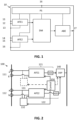
- these two sensors are read-out with a sensor interface circuit comprising two separate analog front-ends, like illustrated with the sensor interface circuit 10 in FIG. 1 .
- a first analog front end AFE1 has input pins 11, 12 and a ground input pin 13.
- a second analog front end AFE2 has input pins 14, 15 and a ground input pin 16.
- the outputs of the analog front ends are connected with a digital module DM which does the analog to digital conversion and possibly also digital processing.
- the output of the digital module is connected with an analog back end ABE the output of which is connected with an output pin 17.
- two ABEs may output both outputs of the AFEs.
- the analog front ends, the digital module and the analog back end are powered with a power supply system PS which can be powered via interface 16.
- one signal (e.g. measured by analog front-end 1) is used as primary output.
- the secondary signal may be used to check by digital processing the correctness of the primary signal.
- the check may be done by an external control unit (ECU).
- ECU external control unit
- a monolithic integrated circuit sensor system implemented on a single semiconductor chip includes a first sensor device having a first signal path for a first sensor signal on a semiconductor chip; and a second sensor device having a second signal path for a second sensor signal on the semiconductor chip, the second signal path distinct from the first signal path, wherein a comparison of the first signal path signal and the second signal path signal provides a sensor system self-test.
- both prior art solutions relate to monolithic integration of the two sensors and the signal paths.
- a monolithic integration is not possible or beneficial, e.g. when the sensor chip uses a different manufacturing technology from the interface chip.
- One example of such a situation is when the sensor is manufactured using a MEMS technology with small number of metal layers (e.g. 1 or 2 metal layers) for connections and the interface chip uses CMOS technology with more than 6 metal layers.
- each sensor chip needs to be connected to the interface chip outside the dies of the sensor chips, for instance using electrical connections (e.g. pads).
- EMC electromagnetic compatibility
- the safety integrity level can be increased by the test circuit while at the same time maintaining the redundancy of at least two front end circuits.
- test input is a signal which spans an operating range of the sensor interface circuit.
- the test input may be a sine wave signal.
- test input may comprise one or more constant signals.
- One of the one or more constant signals may be substantially zero.
- test circuit comprises a test input circuit.
- the test input circuit comprises switches for:
- the processing device is configured for comparing the sensor signal acquisitions by comparing their difference with a predefined threshold
- the sensor interface circuit comprises a separate test input circuit per front end circuit or a single test input circuit for testing all front end circuits.
- the front end circuits may comprise an analog to digital converter (ADC).
- ADC analog to digital converter
- the sensor system may comprise a controller configured for triggering the at least one test input circuit for obtaining a test result.
- the sensor interface circuit comprises an external controller for controlling the sensor interface circuit.
- a sensor interface circuit which comprises at least two sensor inputs each configured to be connected with a different sensor for measuring a same physical parameter and each configured to be connected with a front end circuit for conditioning signals coming from the sensors, the method comprising:
- the method may be used for a sensor interface circuit which has front end circuits with differential inputs.
- the method may comprise:
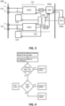
- a sensor interface circuit 100 In a first aspect embodiments of the present invention relate to a sensor interface circuit 100.
- An example of such a sensor interface circuit is illustrated in FIG. 2 .
- the sensor interface circuit 100 comprises at least two sensor inputs 111, 112 each configured to be connected to a separate sensor for measuring a same physical parameter.
- the sensor interface circuit moreover, comprises at least two front-end circuits 121, 122.
- Each sensor input 111, 112 is configured to be connected with one of the front end circuits 121, 122, and each front end circuit 121, 122 is configured for conditioning a signal from the connected sensor input, thus obtaining sensor signal acquisitions from the at least two sensor inputs.
- the sensor interface circuit may comprise more than 2 sensor inputs and more than 2 signal paths may be present.
- the sensor interface circuit may for example comprise a multiplexer so that one or more front ends can connect with the sensor inputs.
- the sensor interface circuit may, for example, comprise 3 or more sensor inputs and 2 front-ends, wherein at least one front-end can read multiple sensors. In such a configuration each sensor may be measuring the same physical parameter.
- the sensor interface circuit moreover, comprises a test circuit comprising test input circuits 131, 132 configured to test correct functionality of at least part of one of the front end circuits 121, 122.
- the correct functionality may for example be tested by checking if the performance meets a predefined requirement.
- the functionality may be considered not correct if, for example, the performance does not meet one or more predefined thresholds.
- the test circuit may, therefore, be configured to apply a test input to the front end circuit under test, and to read a test output of the front end circuit. For example a voltage or a current may be applied as test input.
- the test output is induced by the test input.
- the test circuit is configured to apply the test input intermittently between sensor signal acquisitions.
- the test circuit is configured for comparing the test output with an expected result thus obtaining at least one test result.
- the functionality of the test circuit may be distributed over different components. Reading of the test output and comparing the test output may for example be implemented in a processing device 140.
- the sensor interface circuit 100 comprises a test input circuit 131, 132 for each front end circuit 121, 122.
- test signals of one test input circuit may be interleaved with the test signals of the other test input circuit. This allows to have the sensor signal acquisitions on at least one of the front end circuits.
- the sensor interface circuit moreover, comprises a processing device 140 configured for comparing the sensor signal acquisitions from the different sensor inputs and for combining the comparison with the at least one test result in order to evaluate correct functionality of the sensor interface circuit.
- the front-end circuit comprises analog front-end circuitry for processing the sensor signal in the analog domain. That may include amplification, filtering or any other processing required.
- the front-end circuit may additionally comprise an ADC for converting the output of the analog front-end into a digital representation. This digital representation may be used as input for the processing device.
- the AD conversion is preferably done separately for the different signal paths and optionally also using different types of AD converters between the paths.
- At least two signal paths are present.
- a first path through a first sensor input and a first front end circuit, and a second path through a second sensor input and a second front end circuit.
- a test input circuit may be present in each path or there may be only one test input circuit.
- test input circuit may be applied only to the second path, or may be more thorough for the second path.
- the sensor interface may comprise a test input circuit only for the second path.
- the second front end circuit may be multiplexed between the signal coming from the sensor, and the test output.
- a slower update period for the sensor signal acquisitions may be done for the second path, so that the self test using the test circuit can be performed between the updates.
- the sensor signal acquisitions of the second path may alternate with the test output acquisitions.
- the overall update period of sensor signal acquisitions together with test output acquisitions of the second path may be the same as the update rate of the sensor signal acquisitions of the first path, but some of the samples would be related to the test circuit (also referred to as built-in self test BIST) and some application related, so the update rate for the application related samples might be lower than in the first path.
- the requirements for the second signal path, with respect to update rate are not as stringent as for the first path. This allows to apply significantly more self-tests on the second front-end circuit (and optionally also the secondary sensor), than on the first front-end circuit.
- the test input circuit for the first path does not need to be implemented. For symmetry reasons, it may be present. In that case it may be disabled (during normal operation) to guarantee the full sensor signal update rate for the first path. It may for example be disabled during normal operation and enabled at start-up. In some embodiments of the present invention the check on the first analog front-end may be done on request (e.g. when there is some doubt about the correct performance).
- the sensor interface circuit may be configured for triggering the test circuit for testing the correct functionality of the first and the second front end circuit at start-up or during production testing.
- the interface circuit comprises a controller 150 configured for triggering the at least one test input circuit 131, 132 for obtaining a test result.
- the controller and the processing device may be the same device.
- a microprocessor, a field programmable gate array or a digital signal processor may be used. They may also be separate devices.
- the controller 150 configured for triggering the at least one test input circuit 131, 132 may also control the front end circuits and is also referred to as the front-end control block.
- An example of such a control block 150 is shown in FIG. 2 .
- the operation of the test input circuit(s) is controlled by a controller inside the sensor interface circuit (this may be in the same chip/die).
- the sensor interface circuit may be configured for disconnecting the sensor signal from the front end circuit when the test input circuit is triggered to test correct functionality of the corresponding front-end circuit. This can be implemented using switches, which are controlled from the controller 150.
- the test circuit is configured to test correct functionality (e.g. performance) of at least part of a front end circuit.
- the test input circuit might, for example, not be fully before the Analog front-end (AFE), as show in FIG. 2 , but rather be part of it.
- AFE Analog front-end
- filtering of the signal from the sensor input may be done by a filter circuit at the beginning of the analog front-end. Then it might be best for EMC reasons to have no switches or other active components before this filter.
- the test input circuit is preferably implemented after the filter.
- the test input circuit may be configured for testing also the ADC converter of the front end circuit.
- test circuit may be configured for modifying a front end circuit in order to obtain an oscillating front end circuit (the analog part of the front end circuit is oscillating).
- test input circuit may be implemented separately for each path, or a test input circuit may be shared between paths or part of the test input circuits may be shared. In embodiments of the present invention the test input may for example be applied simultaneously to both paths or in a time multiplexed manner.
- FIG. 2 representing the test input circuits 131, 132 are drawn as separate blocks, part of their functionality may be implemented as shared circuitry.
- the block 131 representing the test circuit for the first path is drawn in dashed lines for indicating that it is optional.
- the built-in self-tests are performed on both front-end circuits of the sensor interface circuit. It might be advantageous however to have one of the front-ends working in normal application mode while the other is being tested, so that at every moment at least one of the two sensor signals is available.
- the sensor interface circuit is configured for connecting an external controller for controlling the sensor interface circuit.
- the test circuit may for example be triggered using an external controller.
- the comparison of the sensor signal acquisitions and the comparison of the test output with the expected result and the combination of the test result with the comparison of the sensor signal acquisitions may be done internally, on a separate die or chip (e.g. at an external controller) or both internally and externally.
- the processing device is a distributed device comprising an internal controller 140a (e.g. a DSP) and an external controller 140b. Both may be implemented on separate chips/dies.
- the external controller is an Engine Control Unit (ECU).
- ECU Engine Control Unit
- the DSP block may perform the analysis between the outputs of the two signal paths and convey the result of the comparison to external controller.
- the comparison result may be combined with the test result in the DSP block and the combined output may be communicated to the external controller (the processing device is a distributed device).
- the output values of the two paths (the sensor signal acquisitions) and the test result may all be communicated to the external controller, but that requires larger bandwidth for the data compared to that part of the processing is done before transferring the data.
- the external controller 140b may optionally be used for triggering the test operation. This may for example be done when there is doubt about the correct operation of the front-end circuits (e.g. the analog parts of the front-end circuits).
- the external controller may be configured for requesting the test operation by communicating with an internal controller (e.g. DSP) which in turn is connected to the Front-end control block 150.
- the connection from the external controller may also be directly to Front-end control block 150, or even directly to the test input circuit(s).
- the processing device may be configured for executing a method comprising the following steps (a flow chart of an exemplary method, in accordance with embodiments of the present invention, is illustrated in FIG. 4 ).
- the processing device may be configured for comparing the sensor signal acquisitions by comparing their difference with a predefined threshold, and
- both front-ends it is possible to detect a fault in one of the two front-ends by comparing the result of both front ends. But both front-ends could suffer from the same or a similar fault, because there might be some correlation between the front-ends. If, for example, the second front-end is tested extensively during operation of the sensor interface circuit, faults can be detected in the second analog front-end. If there is a correlation between the front-ends, correlated faults can be detected which happen simultaneously in both front-ends.
- test circuit and the corresponding test operations, allow to detect dependent faults which influence both analog front-ends. It is thereby noted that faults which influence only one front-end are anyhow detected by comparing the signal acquisitions of both front ends, because both sensors are measuring the same physical parameter, so the outputs of the front ends should be the same.
- the flow-chart in FIG.5 illustrates an exemplary method, in accordance with embodiments of the present invention.
- the processing device is configured for comparing the sensor signal acquisitions of both front ends. If the difference is larger than a predefined threshold, the processing device concludes that the sensor signal acquisitions are not reliable if the test results of both front ends with a test input from test input circuits indicate that both front end circuits are not correctly working or if the test results of both front ends with a test input from test input circuits indicate that both front end circuits are correctly working. If both front ends fail the tests with a test input from test input circuits, it can be concluded that the output is not reliable which is potentially due to a common cause. If both front ends pass, the sensor signal acquisitions (the outputs) are not reliable, probably due to a part which is not covered by the test circuit (e.g. sensor itself, if the sensor is not covered by the test circuit).
- the front-end circuit that passes can be used to generate the output. It should be noted that in this case reliability is reduced. This may be flagged by the processing device to indicate a decrease in reliability of the sensor interface circuit. Indeed, in case of a two sensor system with one path failing, an additional fault (e.g. drift of the sensor) would not be detected anymore.
- the conclusion of the processing device is dependent on the test result of the second front end (in the example the second front end is tested, but this may also be another front end). If this test result is faulty, it is concluded that both analog front ends are faulty. If the test result is OK, it is concluded that the output is reliable.
- all front ends may be tested if the difference between the sensor signal acquisitions is smaller than the predefined threshold.
- test circuit(s) may not only be configured to test correct functionality of the front end circuit, but also of the sensor itself.
- EMC disturbances which are externally induced, such as EMC events might create a big disturbance on the sensor inputs which are connected to the sensor. These errors may be momentary, but they can last long enough to cause a safety issue. If the inputs from the sensor are replaced with an internal test signal to check the correct working of the front-end, such an error might be unnoticed.
- the EMC disturbance is in most cases mainly a common mode signal. There might be also a small differential signal created, e.g. due to some differences in parasitic capacitances.
- a test circuit configured, to apply test inputs derived from the real input pins instead of, or besides applying internally generated test inputs.
- a test input may be generated by connecting input nodes (2 input nodes for receiving a differential signal) of a front-end to the same input pin of the interface circuit (e.g. INP2 pin in FIG. 6 ).
- the test signal is differentially 0, but it has a common mode equal to one of the input pins that can be disturbed by EMC.
- the secondary path test input circuit also comprises a switching configuration to connect the input nodes to the same potential.
- the test input circuit 131, 132 may comprise switches for:
- AD converter is not shown in FIG. 6 and FIG. 7 .
- the AD converter can for example be positioned before the inputs of the processing device 140 or may be part of the processing device 140.
- a small asymmetry may be created between both sides of the differential test signal path by adding for example a small capacitance on one side only, to mimic the worst case asymmetry on the real sensor signal path.
- a RC-filter instead of a single capacitance, but in practice the resistance of the switch might be sufficient so that only the capacitance is needed.
- the capacitor may for example have a capacitance smaller than 1 pF or even smaller than 100 fF.
- a further alternative way to detect EMC influence could be done by adding (or removing) some extra capacitance (or RC) in e.g. the INM2 line only, without shorting INP2 and INM2. Without EMC (and suppose that the useful signal is not changing very fast) both front-end circuits should still give the same results. It is easier, but the disadvantage is that the "availability" of the system might drop, as an EMC issue might already be detected while it is not yet an issue for the normal application.
- the test input circuit may be configured to apply a stable zero differential input which is created internally.
- the test circuit may be configured for comparing the outputs of both tests with shorted inputs, which should normally generate the same result.
- test input circuit comprises switches and a switchable capacitor is pictured in FIG. 7 .
- the test input circuit in this figure, additionally comprises the capacitor (or RC filter) which can be connected to one of the input contacts.
- the capacitor may, for example, be connected between one of the input contacts and the ground or another reference voltage.
- the RC filter may be a low-pass filter.
- test input circuit may also be configured to apply additional input signals to increase the coverage.
- the test input may for example be a signal which spans an operating range of the sensor interface circuit.
- the full input range of the analog front-end is covered by the test input. It is an advantage of embodiments of the present invention that correct operation of the front end circuit is tested for the complete operating range of the front end circuit.
- not only 0 may be applied as differential input, but also for example a signal close to the full scale of the sensor. If the sensor is supplied by analog regulator with a voltage VDDA (and assuming that the sensor output is proportional to its supply), then the test input circuit may be configured to generate internally a differential signal of 10% VDDA. With one signal pure gain errors cannot be detected. If a good coverage is required for non-linearity errors, then the test input circuit needs to be configured for more than 2 signals (preferably significantly more than 2 signals), e.g. 1% VDDA, 2% VDDA, etc.
- the sensor interface has low bandwidth requirements, so it might be good enough to apply only DC signals as test inputs.
- One or more constant signals may be applied.
- the levels of the constant signals may be such that they span the operating range of the sensor interface circuit.
- Applying constant signal(s) has the advantage that the inputs can be easily generated and the output can also be easily checked. In other cases it might be needed to apply also varying signals, e.g. a sine wave need to be applied.
- the output can be checked for example by doing a fast fourier transform (FFT) to check the frequency spectrum.
- FFT fast fourier transform
- the test input circuit may be configured for modifying the front-end circuit such that it starts to oscillate.
- an amplifier of the front-end circuit may be configured with positive feedback while in normal application it uses negative feedback.
- the test output may comprise the frequency and amplitude of the oscillation.
- Such an oscillating signal may also be used to test the ADC.
- the processing device is configured for comparing the sensor signal acquisitions from the different sensor inputs. Their difference may for example be compared with a threshold.
- the threshold may be predefined.
- the sensor performance may influence the safety of the interface circuitry.
- the predefined threshold may be dependent on the difference that can be expected between the two inputs coming from the sensor without a fault being present.
- the threshold for the output comparison should be at least 1.5% of the full scale signal range, normally even more to give some headroom for the interface circuitry. This means that faults in the interface causing an error of 1.5% or less cannot be detected. Even faults in the interface causing an error of 3% might be not detected if the sensor drifted 1.5% in the opposite direction. Typically one likes to detect smaller deviations of the interface chip.
- the processing device is configured for compensating the sensor drift. This may for example be achieved by auto-zeroing. This means that the processing device measures the drift at a certain moment and subtracts it from the results for the following measurements. This can be repeated periodically. This can be done on the 2 outputs (the signal acquisitions for the different sensors) separately if the physical input is known. It can also be done on the difference between both outputs, which has the advantage that the physical input does not need to be known (assuming that both sensors measure the same physical input).
- the processing device may be configured for checking the output difference without drift compensation and the output difference with drift compensation, each with its own threshold. Instead of checking the drift without compensation, the processing device may be configured to check the magnitude of the needed compensation, which is basically the inverse of the drift.
- the check without compensation is done to check the drift of the sensor, which is typically slow.
- the check with compensation can use more tight limits to cover the interface circuit and fast drifts of the sensor.
- the processing device may be configured for tracking the slow drift of the sensor.
- the sensor interface circuit may comprise a lowpass filter with sufficiently high time constant (e.g. 1 minute) to reduce the influence of fast changes due to internal or external faults, including EMC induced deviations.
- analog front-ends may have the same design.
- the separate sensors may each be present on a separate die.
- the separate sensors may be present on a single die with a single membrane, where the different sensors are just using a different set of piezo-resistors.
- a second aspect embodiments of the present invention relate to a method for controlling the integrity of a sensor interface circuit which comprises at least two sensor inputs each configured to be connected with a different sensor for measuring a same physical parameter and each configured to be connected with a front end circuit for conditioning signals coming from the sensors.
- the method comprises:
- a method, in accordance with embodiments of the present invention, may comprise additional features which are also described in the description above.
Landscapes
- Physics & Mathematics (AREA)
- General Physics & Mathematics (AREA)
- Engineering & Computer Science (AREA)
- Theoretical Computer Science (AREA)
- Automation & Control Theory (AREA)
- Testing Electric Properties And Detecting Electric Faults (AREA)
- Testing Or Calibration Of Command Recording Devices (AREA)
- Testing Of Short-Circuits, Discontinuities, Leakage, Or Incorrect Line Connections (AREA)
Claims (15)
- - Eine Sensorschnittstellenschaltung (100), umfassend:- mindestens zwei Sensoreingänge (111, 112), von denen jeder konfiguriert ist, um mit einem separaten Sensor zum Messen eines physikalischen Parameters verbunden zu werden,- mindestens zwei Frontend-Schaltungen (121, 122), wobei jeder Sensoreingang (111, 112) konfiguriert ist, um mit einer der Frontend-Schaltungen (121,122) verbunden zu werden, und wobei jede Frontend-Schaltung (121, 122) zum Aufbereiten eines Signals vom verbundenen Sensoreingang konfiguriert ist, wodurch Sensorsignalerfassungen von den mindestens zwei Sensoreingängen erhalten werden,- eine Testschaltung, die konfiguriert ist, um korrekte Funktionalität mindestens eines Teils von einer der Frontend-Schaltungen (121,122) durch Anwenden eines Testeingangs auf die im Test befindliche Frontend-Schaltung unter Verwendung einer Testeingangsschaltung (131, 132) durch Lesen eines Testausgangs der Frontend-Schaltung, wobei der Testausgang durch den Testeingang induziert wird, und durch Vergleichen des Testausgangs mit einem erwarteten Ergebnis zu testen, wodurch mindestens ein Testergebnis erhalten wird, wobei der Testeingang intermittierend zwischen Sensorsignalerfassungen angewendet wird,- dadurch gekennzeichnet, dass die Sensorschnittstellenschaltung die mindestens zwei Sensoreingänge (111, 112), die mindestens zwei Frontend-Schaltungen (121, 122) und eine Verarbeitungsvorrichtung (140) umfasst, die zum Vergleichen der Sensorsignalerfassungen aus den verschiedenen Sensoreingängen und zum Kombinieren des Vergleichs mit dem mindestens einen Testergebnis konfiguriert ist, um korrekte Funktionalität der Sensorschnittstellenschaltung zu bewerten.
- - Eine Sensorschnittstellenschaltung (100) nach Anspruch 1, wobei der Testeingang ein Signal ist, das einen Betriebsbereich der Sensorschnittstellenschaltung überspannt.
- - Eine Sensorschnittstellenschaltung (100) nach einem der vorstehenden Ansprüche, wobei der Testeingang ein Sinuswellensignal ist.
- - Eine Sensorschnittstellenschaltung (100) nach einem der Ansprüche 1 oder 2, wobei der Testeingang ein oder mehrere konstante Signale umfasst.
- - Eine Sensorschnittstellenschaltung (100) nach Anspruch 4, wobei eines von dem einen oder mehreren konstanten Signalen im Wesentlichen null ist.
- - Eine Sensorschnittstellenschaltung (100) nach einem der vorstehenden Ansprüche, wobei die Testeingangsschaltung (132) Schalter umfasst zum:- Verbinden von Eingangs-Pins von einem der Sensoreingänge (112) mit Eingangskontakten von einer der Frontend-Schaltungen (122) zum Erhalten von Sensorsignalerfassungen,- Verbinden von einem der Eingangs-Pins des Sensoreingangs (112) mit beiden Eingangskontakten der Frontend-Schaltung (122), und Trennen des anderen Sensoreingangs (112) von der Frontend-Schaltung (122) zum Erhalten des Testergebnisses.
- - Eine Sensorschnittstellenschaltung (100) nach Anspruch 6, wobei die Testeingangsschaltung einen Kondensator umfasst, der mit einem der Eingangskontakte verbunden werden kann.
- - Eine Sensorschnittstellenschaltung (100) nach einem der vorstehenden Ansprüche, wobei die Verarbeitungsvorrichtung (140) zum Vergleichen der Sensorsignalerfassungen durch Vergleichen ihres Unterschieds zu einer vordefinierten Schwelle konfiguriert ist, und- zum Bestimmen, dass die Sensorsignalerfassungen nicht zuverlässig sind, wenn der Unterschied größer als die Schwelle ist, und- zum Bestimmen, dass die Sensorsignalerfassungen nicht zuverlässig sind, wenn der Unterschied kleiner als die Schwelle ist und das Testergebnis von einer der Frontend-Schaltungen angibt, dass sie nicht korrekt arbeitet, und- zum Bestimmen, dass die Sensorsignalerfassungen zuverlässig sind, wenn der Unterschied kleiner als die Schwelle ist und das eine oder mehrere Testergebnisse von einer der einen oder mehreren Frontend-Schaltungen angibt, dass sie korrekt arbeitet.
- - Eine Sensorschnittstellenschaltung (100) nach einem der vorstehenden Ansprüche, wobei die Sensorschnittstellenschaltung (100) eine separate Testeingangsschaltung (131,132) je Frontend-Schaltung (121,122) oder eine einzige Testeingangsschaltung zum Testen aller Frontend-Schaltungen umfasst.
- - Eine Sensorschnittstellenschaltung (100) nach Anspruch 9, wobei die Verarbeitungsvorrichtung (140) konfiguriert ist zum:- Vergleichen der Sensorsignalerfassungen von den mindestens zwei Sensoreingängen durch Vergleichen ihres Unterschieds zu einer vordefinierten Schwelle, und, wenn der Unterschied größer als die Schwelle ist,- zum Bestimmen, dass die Sensorsignalerfassungen nicht zuverlässig sind, wenn mindestens ein Testergebnis von jeder Frontend-Schaltung angibt, dass alle Frontend-Schaltungen nicht korrekt arbeiten, oder wenn die Testergebnisse angeben, dass alle Frontend-Schaltungen korrekt arbeiten,- zum Bestimmen, dass die Sensorsignalerfassung einer Frontend-Schaltung, für die das Testergebnis angibt, dass sie korrekt arbeitet, verwendet werden sollte, wenn das Testergebnis der mindestens einen Frontend-Schaltung angibt, dass sie nicht korrekt arbeitet,
und wenn der Unterschied kleiner als die Schwelle ist, zum Erhalten des Testergebnisses von einer der Frontend-Schaltungen und- zum Bestimmen, dass die Sensorsignalerfassungen nicht zuverlässig sind, wenn das Testergebnis angibt, dass sie nicht korrekt arbeitet,- zum Bestimmen, dass die Sensorsignalerfassungen zuverlässig sind, wenn das Testergebnis angibt, dass sie korrekt arbeitet. - - Eine Sensorschnittstellenschaltung (100) nach einem der vorstehenden Ansprüche, wobei die Frontend-Schaltungen einen Analog-Digital-Wandler (ADC) umfassen.
- - Eine Sensorschnittstellenschaltung (100) nach einem der vorstehenden Ansprüche, wobei das Sensorsystem eine Steuereinheit (150) umfasst, die zum Auslösen der mindestens einen Testschaltung (131,132) zum Erhalten eines Testergebnisses konfiguriert ist.
- - Eine Sensorschnittstellenschaltung (100) nach einem der vorstehenden Ansprüche, die zum Verbinden einer externen Steuereinheit zum Steuern der Sensorschnittstellenschaltung konfiguriert ist.
- - Ein Verfahren zum Steuern der Integrität einer Sensorschnittstellenschaltung, die mindestens zwei Sensoreingänge umfasst, die jeweils konfiguriert sind, um mit einem anderen Sensor zum Messen eines selben physikalischen Parameters verbunden zu werden, und jeweils konfiguriert sind, um mit einer Frontend-Schaltung zum Aufbereiten von Signalen verbunden zu werden, die von den Sensoren kommen, wobei das Verfahren umfasst:- Erfassen von Signalen von den Frontend-Schaltungen, wodurch Sensorsignalerfassungen erhalten werden,- intermittierend Anwenden eines Testsignals auf mindestens eine der Frontend-Schaltungen, und Lesen eines Testausgangs der Frontend-Schaltung, der durch das Testsignal induziert wird,- Vergleichen des Testausgangs mit einem erwarteten Ergebnis, wodurch mindestens ein Testergebnis erhalten wird,- dadurch gekennzeichnet, dass die Signale von den mindestens zwei Frontend-Schaltungen erfasst werden, und das Verfahren Vergleichen der Sensorsignalerfassungen aus den verschiedenen Sensoreingängen und Kombinieren des Vergleichs mit dem mindestens einen Testergebnis umfasst, um korrekte Funktionalität der Sensorschnittstellenschaltung zu bewerten.
- - Ein Verfahren nach Anspruch 14, für eine Sensorschnittstellenschaltung, die Frontend-Schaltungen mit verschiedenen Eingängen aufweist, wobei das Verfahren umfasst:- Verbinden von Eingangs-Pins von einem der Sensoreingänge mit Eingangskontakten von einer der Frontend-Schaltungen zum Erhalten von Sensorsignalerfassungen,- Verbinden von einem der Eingangs-Pins des Sensoreingangs mit beiden Eingangskontakten der Frontend-Schaltung, und Trennen des anderen Sensoreingangs von der Frontend-Schaltung zum Erhalten des Testergebnisses.
Priority Applications (3)
| Application Number | Priority Date | Filing Date | Title |
|---|---|---|---|
| EP21169537.4A EP4080168B1 (de) | 2021-04-20 | 2021-04-20 | Sensorschnittstellen für funktionelle sicherheitsanwendungen |
| US17/724,198 US12206428B2 (en) | 2021-04-20 | 2022-04-19 | Sensor interfaces for functional safety applications |
| CN202210420884.0A CN115220376A (zh) | 2021-04-20 | 2022-04-20 | 用于功能安全应用的传感器接口 |
Applications Claiming Priority (1)
| Application Number | Priority Date | Filing Date | Title |
|---|---|---|---|
| EP21169537.4A EP4080168B1 (de) | 2021-04-20 | 2021-04-20 | Sensorschnittstellen für funktionelle sicherheitsanwendungen |
Publications (2)
| Publication Number | Publication Date |
|---|---|
| EP4080168A1 EP4080168A1 (de) | 2022-10-26 |
| EP4080168B1 true EP4080168B1 (de) | 2024-10-16 |
Family
ID=75625424
Family Applications (1)
| Application Number | Title | Priority Date | Filing Date |
|---|---|---|---|
| EP21169537.4A Active EP4080168B1 (de) | 2021-04-20 | 2021-04-20 | Sensorschnittstellen für funktionelle sicherheitsanwendungen |
Country Status (3)
| Country | Link |
|---|---|
| US (1) | US12206428B2 (de) |
| EP (1) | EP4080168B1 (de) |
| CN (1) | CN115220376A (de) |
Families Citing this family (3)
| Publication number | Priority date | Publication date | Assignee | Title |
|---|---|---|---|---|
| CN117215177A (zh) * | 2023-11-09 | 2023-12-12 | 北京控制工程研究所 | 一种天地往返一体化控制系统及控制方法 |
| EP4579194B1 (de) * | 2023-12-27 | 2026-04-29 | Melexis Technologies SA | Sensorvorrichtung für sicherheitskritische anwendungen |
| CN119780749A (zh) * | 2025-03-10 | 2025-04-08 | 宁德时代新能源科技股份有限公司 | 故障检测方法、装置、系统以及存储介质 |
Family Cites Families (17)
| Publication number | Priority date | Publication date | Assignee | Title |
|---|---|---|---|---|
| WO2000055652A1 (en) * | 1999-03-17 | 2000-09-21 | Input/Output, Inc. | Calibration of sensors |
| DE102006050832B4 (de) * | 2006-10-27 | 2012-07-26 | Infineon Technologies Ag | In-Betrieb-Test eines Signalpfades mittels wenigstens zweier Testsignale |
| US8442787B2 (en) | 2010-04-30 | 2013-05-14 | Infineon Technologies Ag | Apparatus, sensor circuit, and method for operating an apparatus or a sensor circuit |
| US9346441B2 (en) | 2010-09-24 | 2016-05-24 | Infineon Technologies Ag | Sensor self-diagnostics using multiple signal paths |
| US9874609B2 (en) | 2010-09-24 | 2018-01-23 | Infineon Technologies Ag | Sensor self-diagnostics using multiple signal paths |
| DE102012201170A1 (de) * | 2012-01-27 | 2013-08-01 | Dr. Johannes Heidenhain Gmbh | Vorrichtung zur Übertragung von Sensordaten |
| DE102012002013B4 (de) * | 2012-02-03 | 2015-09-10 | Krohne Messtechnik Gmbh | Prüfung einer Messgerätanordnung, entsprechende Messgerätanordnung und Prüfanordnung |
| CN103245372B (zh) * | 2012-02-13 | 2017-04-12 | 富泰华工业(深圳)有限公司 | 电桥式传感器侦测电路 |
| US9001446B1 (en) * | 2014-02-06 | 2015-04-07 | Lsi Corporation | System and method for power saving modes in multi-sensor magnetic recording |
| US9535099B2 (en) * | 2014-05-19 | 2017-01-03 | Honeywell International Inc. | Systems and methods that allow for simultaneous sensor and signal conditioning circuit performance testing |
| US9804222B2 (en) * | 2014-11-14 | 2017-10-31 | Allegro Microsystems, Llc | Magnetic field sensor with shared path amplifier and analog-to-digital-converter |
| KR102043210B1 (ko) * | 2016-04-19 | 2019-11-12 | 인피니온 테크놀로지스 아게 | 다중 신호 경로들을 사용하는 센서 자체 진단 |
| EP3351905B1 (de) * | 2017-01-19 | 2020-03-11 | Melexis Technologies NV | Sensor mit selbstdiagnosefunktion |
| EP3855129B1 (de) * | 2017-03-22 | 2023-10-25 | Knowles Electronics, LLC | Interface schaltkreis für einen kapazitiven sensor |
| EP3581951A1 (de) * | 2018-06-12 | 2019-12-18 | Melexis Bulgaria Ltd. | Sensorsättigungsfehlererkennung |
| CN209894206U (zh) * | 2019-06-27 | 2020-01-03 | 成都鸿思达科技有限公司 | 一种能够自检的传感器故障检测电路 |
| CN212484112U (zh) * | 2020-06-09 | 2021-02-05 | 江苏集萃深度感知技术研究所有限公司 | 一种基于单片机的传感器信号处理系统 |
-
2021
- 2021-04-20 EP EP21169537.4A patent/EP4080168B1/de active Active
-
2022
- 2022-04-19 US US17/724,198 patent/US12206428B2/en active Active
- 2022-04-20 CN CN202210420884.0A patent/CN115220376A/zh active Pending
Also Published As
| Publication number | Publication date |
|---|---|
| US20220337263A1 (en) | 2022-10-20 |
| EP4080168A1 (de) | 2022-10-26 |
| US12206428B2 (en) | 2025-01-21 |
| CN115220376A (zh) | 2022-10-21 |
Similar Documents
| Publication | Publication Date | Title |
|---|---|---|
| US12206428B2 (en) | Sensor interfaces for functional safety applications | |
| CN110595524B (zh) | 传感器饱和故障检测 | |
| CN104964703B (zh) | 用于单片传感器系统的高效诊断方法 | |
| US10067173B2 (en) | Method for sensor readout with redundancy-checking | |
| US6040779A (en) | Method and circuit for monitoring the functioning of a sensor bridge | |
| US10228414B2 (en) | Capacitive sensor testing | |
| CN107257915B (zh) | 具有改进的故障识别的测量电桥组件和方法 | |
| US10534015B2 (en) | Sensor and method for diagnosing sensor | |
| CN101283282B (zh) | 电流测量电路和诊断电流测量电路中的故障的方法 | |
| US10436659B2 (en) | Pressure sensor device and method for testing the pressure sensor device | |
| US6357298B1 (en) | Micromechanical sensor and method for operating the sensor | |
| US5612488A (en) | Semiconductor acceleration detecting device | |
| US7088108B2 (en) | Method for detecting an offset drift in a wheatstone measuring bridge | |
| EP3144640B1 (de) | Sensoranordnung und verfahren zum betrieb eines sensors | |
| US20250199041A1 (en) | Capacitive sensor and method for operating a capacitive sensor | |
| US7233151B2 (en) | Apparatus and method for diagnosing failure of fuel level sensors | |
| CN110824411B (zh) | 一种参数检测电路及方法 | |
| JP7822224B2 (ja) | 測定回路及びこれを用いる測定システム | |
| CN114879009B (zh) | 电容测量装置及电容测量方法 | |
| CN110824410B (zh) | 一种参数检测电路及方法 | |
| KR102035924B1 (ko) | 고장진단회로 일체형 브릿지 구조의 압력센서 및 브릿지 구조 압력센서의 고장진단 방법 | |
| JP2023111659A (ja) | 物理量センサーモジュールおよび物理量センサーの診断方法 | |
| JP2000195397A (ja) | リレ―診断装置 | |
| JP2014013219A (ja) | 半導体センサの検査装置 | |
| CN115776300A (zh) | 一种模数转换器的检测电路、检测方法和数据采样系统 |
Legal Events
| Date | Code | Title | Description |
|---|---|---|---|
| PUAI | Public reference made under article 153(3) epc to a published international application that has entered the european phase |
Free format text: ORIGINAL CODE: 0009012 |
|
| STAA | Information on the status of an ep patent application or granted ep patent |
Free format text: STATUS: THE APPLICATION HAS BEEN PUBLISHED |
|
| AK | Designated contracting states |
Kind code of ref document: A1 Designated state(s): AL AT BE BG CH CY CZ DE DK EE ES FI FR GB GR HR HU IE IS IT LI LT LU LV MC MK MT NL NO PL PT RO RS SE SI SK SM TR |
|
| STAA | Information on the status of an ep patent application or granted ep patent |
Free format text: STATUS: REQUEST FOR EXAMINATION WAS MADE |
|
| 17P | Request for examination filed |
Effective date: 20230418 |
|
| RBV | Designated contracting states (corrected) |
Designated state(s): AL AT BE BG CH CY CZ DE DK EE ES FI FR GB GR HR HU IE IS IT LI LT LU LV MC MK MT NL NO PL PT RO RS SE SI SK SM TR |
|
| GRAP | Despatch of communication of intention to grant a patent |
Free format text: ORIGINAL CODE: EPIDOSNIGR1 |
|
| STAA | Information on the status of an ep patent application or granted ep patent |
Free format text: STATUS: GRANT OF PATENT IS INTENDED |
|
| INTG | Intention to grant announced |
Effective date: 20240717 |
|
| GRAS | Grant fee paid |
Free format text: ORIGINAL CODE: EPIDOSNIGR3 |
|
| GRAA | (expected) grant |
Free format text: ORIGINAL CODE: 0009210 |
|
| STAA | Information on the status of an ep patent application or granted ep patent |
Free format text: STATUS: THE PATENT HAS BEEN GRANTED |
|
| AK | Designated contracting states |
Kind code of ref document: B1 Designated state(s): AL AT BE BG CH CY CZ DE DK EE ES FI FR GB GR HR HU IE IS IT LI LT LU LV MC MK MT NL NO PL PT RO RS SE SI SK SM TR |
|
| REG | Reference to a national code |
Ref country code: GB Ref legal event code: FG4D |
|
| REG | Reference to a national code |
Ref country code: CH Ref legal event code: EP |
|
| REG | Reference to a national code |
Ref country code: IE Ref legal event code: FG4D |
|
| REG | Reference to a national code |
Ref country code: DE Ref legal event code: R096 Ref document number: 602021020223 Country of ref document: DE |
|
| REG | Reference to a national code |
Ref country code: LT Ref legal event code: MG9D |
|
| REG | Reference to a national code |
Ref country code: NL Ref legal event code: MP Effective date: 20241016 |
|
| REG | Reference to a national code |
Ref country code: AT Ref legal event code: MK05 Ref document number: 1733243 Country of ref document: AT Kind code of ref document: T Effective date: 20241016 |
|
| PG25 | Lapsed in a contracting state [announced via postgrant information from national office to epo] |
Ref country code: NL Free format text: LAPSE BECAUSE OF FAILURE TO SUBMIT A TRANSLATION OF THE DESCRIPTION OR TO PAY THE FEE WITHIN THE PRESCRIBED TIME-LIMIT Effective date: 20241016 |
|
| PG25 | Lapsed in a contracting state [announced via postgrant information from national office to epo] |
Ref country code: NL Free format text: LAPSE BECAUSE OF FAILURE TO SUBMIT A TRANSLATION OF THE DESCRIPTION OR TO PAY THE FEE WITHIN THE PRESCRIBED TIME-LIMIT Effective date: 20241016 |
|
| PG25 | Lapsed in a contracting state [announced via postgrant information from national office to epo] |
Ref country code: IS Free format text: LAPSE BECAUSE OF FAILURE TO SUBMIT A TRANSLATION OF THE DESCRIPTION OR TO PAY THE FEE WITHIN THE PRESCRIBED TIME-LIMIT Effective date: 20250216 Ref country code: HR Free format text: LAPSE BECAUSE OF FAILURE TO SUBMIT A TRANSLATION OF THE DESCRIPTION OR TO PAY THE FEE WITHIN THE PRESCRIBED TIME-LIMIT Effective date: 20241016 Ref country code: PT Free format text: LAPSE BECAUSE OF FAILURE TO SUBMIT A TRANSLATION OF THE DESCRIPTION OR TO PAY THE FEE WITHIN THE PRESCRIBED TIME-LIMIT Effective date: 20250217 |
|
| PG25 | Lapsed in a contracting state [announced via postgrant information from national office to epo] |
Ref country code: FI Free format text: LAPSE BECAUSE OF FAILURE TO SUBMIT A TRANSLATION OF THE DESCRIPTION OR TO PAY THE FEE WITHIN THE PRESCRIBED TIME-LIMIT Effective date: 20241016 |
|
| PG25 | Lapsed in a contracting state [announced via postgrant information from national office to epo] |
Ref country code: BG Free format text: LAPSE BECAUSE OF FAILURE TO SUBMIT A TRANSLATION OF THE DESCRIPTION OR TO PAY THE FEE WITHIN THE PRESCRIBED TIME-LIMIT Effective date: 20241016 |
|
| PG25 | Lapsed in a contracting state [announced via postgrant information from national office to epo] |
Ref country code: ES Free format text: LAPSE BECAUSE OF FAILURE TO SUBMIT A TRANSLATION OF THE DESCRIPTION OR TO PAY THE FEE WITHIN THE PRESCRIBED TIME-LIMIT Effective date: 20241016 |
|
| PG25 | Lapsed in a contracting state [announced via postgrant information from national office to epo] |
Ref country code: NO Free format text: LAPSE BECAUSE OF FAILURE TO SUBMIT A TRANSLATION OF THE DESCRIPTION OR TO PAY THE FEE WITHIN THE PRESCRIBED TIME-LIMIT Effective date: 20250116 |
|
| PG25 | Lapsed in a contracting state [announced via postgrant information from national office to epo] |
Ref country code: LV Free format text: LAPSE BECAUSE OF FAILURE TO SUBMIT A TRANSLATION OF THE DESCRIPTION OR TO PAY THE FEE WITHIN THE PRESCRIBED TIME-LIMIT Effective date: 20241016 Ref country code: GR Free format text: LAPSE BECAUSE OF FAILURE TO SUBMIT A TRANSLATION OF THE DESCRIPTION OR TO PAY THE FEE WITHIN THE PRESCRIBED TIME-LIMIT Effective date: 20250117 Ref country code: AT Free format text: LAPSE BECAUSE OF FAILURE TO SUBMIT A TRANSLATION OF THE DESCRIPTION OR TO PAY THE FEE WITHIN THE PRESCRIBED TIME-LIMIT Effective date: 20241016 |
|
| PG25 | Lapsed in a contracting state [announced via postgrant information from national office to epo] |
Ref country code: PL Free format text: LAPSE BECAUSE OF FAILURE TO SUBMIT A TRANSLATION OF THE DESCRIPTION OR TO PAY THE FEE WITHIN THE PRESCRIBED TIME-LIMIT Effective date: 20241016 |
|
| PG25 | Lapsed in a contracting state [announced via postgrant information from national office to epo] |
Ref country code: RS Free format text: LAPSE BECAUSE OF FAILURE TO SUBMIT A TRANSLATION OF THE DESCRIPTION OR TO PAY THE FEE WITHIN THE PRESCRIBED TIME-LIMIT Effective date: 20250116 |
|
| P01 | Opt-out of the competence of the unified patent court (upc) registered |
Free format text: CASE NUMBER: APP_15950/2025 Effective date: 20250401 |
|
| PG25 | Lapsed in a contracting state [announced via postgrant information from national office to epo] |
Ref country code: SM Free format text: LAPSE BECAUSE OF FAILURE TO SUBMIT A TRANSLATION OF THE DESCRIPTION OR TO PAY THE FEE WITHIN THE PRESCRIBED TIME-LIMIT Effective date: 20241016 |
|
| PGFP | Annual fee paid to national office [announced via postgrant information from national office to epo] |
Ref country code: DE Payment date: 20250319 Year of fee payment: 5 |
|
| PG25 | Lapsed in a contracting state [announced via postgrant information from national office to epo] |
Ref country code: DK Free format text: LAPSE BECAUSE OF FAILURE TO SUBMIT A TRANSLATION OF THE DESCRIPTION OR TO PAY THE FEE WITHIN THE PRESCRIBED TIME-LIMIT Effective date: 20241016 |
|
| REG | Reference to a national code |
Ref country code: DE Ref legal event code: R097 Ref document number: 602021020223 Country of ref document: DE |
|
| PG25 | Lapsed in a contracting state [announced via postgrant information from national office to epo] |
Ref country code: EE Free format text: LAPSE BECAUSE OF FAILURE TO SUBMIT A TRANSLATION OF THE DESCRIPTION OR TO PAY THE FEE WITHIN THE PRESCRIBED TIME-LIMIT Effective date: 20241016 |
|
| PG25 | Lapsed in a contracting state [announced via postgrant information from national office to epo] |
Ref country code: RO Free format text: LAPSE BECAUSE OF FAILURE TO SUBMIT A TRANSLATION OF THE DESCRIPTION OR TO PAY THE FEE WITHIN THE PRESCRIBED TIME-LIMIT Effective date: 20241016 |
|
| PG25 | Lapsed in a contracting state [announced via postgrant information from national office to epo] |
Ref country code: SK Free format text: LAPSE BECAUSE OF FAILURE TO SUBMIT A TRANSLATION OF THE DESCRIPTION OR TO PAY THE FEE WITHIN THE PRESCRIBED TIME-LIMIT Effective date: 20241016 |
|
| PG25 | Lapsed in a contracting state [announced via postgrant information from national office to epo] |
Ref country code: CZ Free format text: LAPSE BECAUSE OF FAILURE TO SUBMIT A TRANSLATION OF THE DESCRIPTION OR TO PAY THE FEE WITHIN THE PRESCRIBED TIME-LIMIT Effective date: 20241016 |
|
| PG25 | Lapsed in a contracting state [announced via postgrant information from national office to epo] |
Ref country code: IT Free format text: LAPSE BECAUSE OF FAILURE TO SUBMIT A TRANSLATION OF THE DESCRIPTION OR TO PAY THE FEE WITHIN THE PRESCRIBED TIME-LIMIT Effective date: 20241016 |
|
| PLBE | No opposition filed within time limit |
Free format text: ORIGINAL CODE: 0009261 |
|
| STAA | Information on the status of an ep patent application or granted ep patent |
Free format text: STATUS: NO OPPOSITION FILED WITHIN TIME LIMIT |
|
| PG25 | Lapsed in a contracting state [announced via postgrant information from national office to epo] |
Ref country code: SE Free format text: LAPSE BECAUSE OF FAILURE TO SUBMIT A TRANSLATION OF THE DESCRIPTION OR TO PAY THE FEE WITHIN THE PRESCRIBED TIME-LIMIT Effective date: 20241016 |
|
| 26N | No opposition filed |
Effective date: 20250717 |
|
| REG | Reference to a national code |
Ref country code: CH Ref legal event code: H13 Free format text: ST27 STATUS EVENT CODE: U-0-0-H10-H13 (AS PROVIDED BY THE NATIONAL OFFICE) Effective date: 20251125 |
|
| PG25 | Lapsed in a contracting state [announced via postgrant information from national office to epo] |
Ref country code: LU Free format text: LAPSE BECAUSE OF NON-PAYMENT OF DUE FEES Effective date: 20250420 |
|
| PG25 | Lapsed in a contracting state [announced via postgrant information from national office to epo] |
Ref country code: MC Free format text: LAPSE BECAUSE OF FAILURE TO SUBMIT A TRANSLATION OF THE DESCRIPTION OR TO PAY THE FEE WITHIN THE PRESCRIBED TIME-LIMIT Effective date: 20241016 |
|
| GBPC | Gb: european patent ceased through non-payment of renewal fee |
Effective date: 20250420 |
|
| REG | Reference to a national code |
Ref country code: BE Ref legal event code: MM Effective date: 20250430 |
|
| PG25 | Lapsed in a contracting state [announced via postgrant information from national office to epo] |
Ref country code: GB Free format text: LAPSE BECAUSE OF NON-PAYMENT OF DUE FEES Effective date: 20250420 |
|
| PG25 | Lapsed in a contracting state [announced via postgrant information from national office to epo] |
Ref country code: BE Free format text: LAPSE BECAUSE OF NON-PAYMENT OF DUE FEES Effective date: 20250430 |
|
| PG25 | Lapsed in a contracting state [announced via postgrant information from national office to epo] |
Ref country code: CH Free format text: LAPSE BECAUSE OF NON-PAYMENT OF DUE FEES Effective date: 20250430 |
|
| PG25 | Lapsed in a contracting state [announced via postgrant information from national office to epo] |
Ref country code: IE Free format text: LAPSE BECAUSE OF NON-PAYMENT OF DUE FEES Effective date: 20250420 |
|
| PGFP | Annual fee paid to national office [announced via postgrant information from national office to epo] |
Ref country code: FR Payment date: 20260320 Year of fee payment: 6 |