EP4086497A1 - Coupleur - Google Patents
Coupleur Download PDFInfo
- Publication number
- EP4086497A1 EP4086497A1 EP22172041.0A EP22172041A EP4086497A1 EP 4086497 A1 EP4086497 A1 EP 4086497A1 EP 22172041 A EP22172041 A EP 22172041A EP 4086497 A1 EP4086497 A1 EP 4086497A1
- Authority
- EP
- European Patent Office
- Prior art keywords
- coupling
- valve
- cylinder
- flow path
- valve member
- Prior art date
- Legal status (The legal status is an assumption and is not a legal conclusion. Google has not performed a legal analysis and makes no representation as to the accuracy of the status listed.)
- Granted
Links
Images


Classifications
-
- F—MECHANICAL ENGINEERING; LIGHTING; HEATING; WEAPONS; BLASTING
- F16—ENGINEERING ELEMENTS AND UNITS; GENERAL MEASURES FOR PRODUCING AND MAINTAINING EFFECTIVE FUNCTIONING OF MACHINES OR INSTALLATIONS; THERMAL INSULATION IN GENERAL
- F16L—PIPES; JOINTS OR FITTINGS FOR PIPES; SUPPORTS FOR PIPES, CABLES OR PROTECTIVE TUBING; MEANS FOR THERMAL INSULATION IN GENERAL
- F16L29/00—Joints with fluid cut-off means
- F16L29/04—Joints with fluid cut-off means with a cut-off device in each of the two pipe ends, the cut-off devices being automatically opened when the coupling is applied
-
- F—MECHANICAL ENGINEERING; LIGHTING; HEATING; WEAPONS; BLASTING
- F16—ENGINEERING ELEMENTS AND UNITS; GENERAL MEASURES FOR PRODUCING AND MAINTAINING EFFECTIVE FUNCTIONING OF MACHINES OR INSTALLATIONS; THERMAL INSULATION IN GENERAL
- F16L—PIPES; JOINTS OR FITTINGS FOR PIPES; SUPPORTS FOR PIPES, CABLES OR PROTECTIVE TUBING; MEANS FOR THERMAL INSULATION IN GENERAL
- F16L29/00—Joints with fluid cut-off means
- F16L29/02—Joints with fluid cut-off means with a cut-off device in one of the two pipe ends, the cut-off device being automatically opened when the coupling is applied
-
- F—MECHANICAL ENGINEERING; LIGHTING; HEATING; WEAPONS; BLASTING
- F16—ENGINEERING ELEMENTS AND UNITS; GENERAL MEASURES FOR PRODUCING AND MAINTAINING EFFECTIVE FUNCTIONING OF MACHINES OR INSTALLATIONS; THERMAL INSULATION IN GENERAL
- F16L—PIPES; JOINTS OR FITTINGS FOR PIPES; SUPPORTS FOR PIPES, CABLES OR PROTECTIVE TUBING; MEANS FOR THERMAL INSULATION IN GENERAL
- F16L55/00—Devices or appurtenances for use in, or in connection with, pipes or pipe systems
- F16L55/10—Means for stopping flow in pipes or hoses
- F16L55/1007—Couplings closed automatically when broken
-
- F—MECHANICAL ENGINEERING; LIGHTING; HEATING; WEAPONS; BLASTING
- F16—ENGINEERING ELEMENTS AND UNITS; GENERAL MEASURES FOR PRODUCING AND MAINTAINING EFFECTIVE FUNCTIONING OF MACHINES OR INSTALLATIONS; THERMAL INSULATION IN GENERAL
- F16L—PIPES; JOINTS OR FITTINGS FOR PIPES; SUPPORTS FOR PIPES, CABLES OR PROTECTIVE TUBING; MEANS FOR THERMAL INSULATION IN GENERAL
- F16L2201/00—Special arrangements for pipe couplings
- F16L2201/30—Detecting leaks
-
- F—MECHANICAL ENGINEERING; LIGHTING; HEATING; WEAPONS; BLASTING
- F16—ENGINEERING ELEMENTS AND UNITS; GENERAL MEASURES FOR PRODUCING AND MAINTAINING EFFECTIVE FUNCTIONING OF MACHINES OR INSTALLATIONS; THERMAL INSULATION IN GENERAL
- F16L—PIPES; JOINTS OR FITTINGS FOR PIPES; SUPPORTS FOR PIPES, CABLES OR PROTECTIVE TUBING; MEANS FOR THERMAL INSULATION IN GENERAL
- F16L23/00—Flanged joints
- F16L23/02—Flanged joints the flanges being connected by members tensioned axially
- F16L23/036—Flanged joints the flanges being connected by members tensioned axially characterised by the tensioning members, e.g. specially adapted bolts or C-clamps
-
- F—MECHANICAL ENGINEERING; LIGHTING; HEATING; WEAPONS; BLASTING
- F16—ENGINEERING ELEMENTS AND UNITS; GENERAL MEASURES FOR PRODUCING AND MAINTAINING EFFECTIVE FUNCTIONING OF MACHINES OR INSTALLATIONS; THERMAL INSULATION IN GENERAL
- F16L—PIPES; JOINTS OR FITTINGS FOR PIPES; SUPPORTS FOR PIPES, CABLES OR PROTECTIVE TUBING; MEANS FOR THERMAL INSULATION IN GENERAL
- F16L55/00—Devices or appurtenances for use in, or in connection with, pipes or pipe systems
- F16L55/10—Means for stopping flow in pipes or hoses
- F16L55/1015—Couplings closed automatically when disengaging force exceeds preselected value
Definitions
- the present disclosure relates to a coupling for use with comestible products.
- Couplings for fluid flow lines which incorporate a self-closing mechanism are well known in the art, particularly in applications which involve potentially hazardous fluids where spillages must be avoided.
- a first aspect of the disclosure provides a coupling comprising:
- the coupling is for use with comestible products, which may be provided in particulate form, fluid form (liquid or gas), or as particles suspended or entrained in a fluid (liquid or gas).
- the closure mechanism includes a biasing member for biasing the valve member into the closed position.
- the coupling is configured such that, if the first and second bodies become decoupled from one another, the biasing member drives the valve member to the closed position.
- the biasing member is operable in a first chamber which is isolated from the continuous flow path.
- biasing member in a chamber isolated from the continuous flow path promotes a hygienic, more easily cleanable coupling.
- the biasing member is in operable communication with the valve member.
- the interior of the cylinder is isolated from a flow of product from the continuous flow path.
- the valve member comprises a piston-like body, a portion of which extends within the cylinder and is arranged for reciprocation within the cylinder, for moving the valve member between the open and closed positions.
- Such a piston/cylinder arrangement promotes simple and controlled movement of the valve member, and allows for a hygienic, more easily cleanable flow path.
- the coupling further comprises a cylinder seal located between the cylinder and piston-like body for sealing the cylinder against product ingress.
- test port enables an operator to more easily monitor the integrity of the cylinder seal between the cylinder and the valve body.
- the cylinder and test port together define a first leakage flow path between the cylinder seal and the test port for monitoring the integrity of the sealing effect between the cylinder and the piston-like body.
- the cylinder is arranged within the first flow path, such that product is able to flow around a circumference of the cylinder as it passes along the first flow path.
- extending the first flow path around the circumference of the first chamber helps to improve the flow capacity of the coupling.
- the use of a plurality of arms, such as between two and four arms, typically arranged in a uniform radial array, with the cylinder as a hub, can provide for stability of the cylinder without undue impact on the flow capacity of the first flow path.
- the plurality of supporting arms are integrally formed as part of the first body and/or the cylinder.
- forming the first chamber integrally with the first body helps to reduce the number of parts required for the coupling, thereby making the coupling simpler to manufacture.
- the piston-like body comprises an internal bore, and wherein the biasing member extends at least partially within said internal bore. It will be understood, therefore, that the first chamber comprises said internal bore in exemplary embodiments.
- the piston-like body extends from an open end of the cylinder.
- the biasing member extends within the internal bore beyond the open end of the cylinder.
- a coil spring provides an effective means for biasing the valve member into the closed position.
- the spring is arranged to be under compressive load when the valve member is in the closed position which urges the valve member into the closed position, the coupling is able to further minimise the likelihood product egress when the valve is in the closed position.
- the valve member has a valve head, e.g. located external to the cylinder, wherein the valve head is configured to cooperate with an annular seal surface within the coupling, for preventing product flow through the first body when the valve member is in the closed position.
- the annular seal surface is provided on the first body; optionally, wherein the annular seal surface is part of a wall of the first flow path.
- valve head includes an annular seal element arranged for cooperation with said annular seal surface.
- annular seal element helps to prevent direct contact between the respective valve members thereby helping to reduce the likelihood product egress when the valve is in the closed position.
- the annular seal element is of deformable nature. Using a deformable seal allows for the seal element to be compressed into sealing abutment with the seal surface.
- the coupling is configured such that the biasing member applies a load to urge the annular seal against the seal surface of the first body when the valve member is in the closed position, e.g. to compress the seal element into sealing abutment with the seal surface.
- the valve member comprises a valve head and a valve body which are formed as separate, releasably connectable components, wherein an annular seal is housed between the valve head and the valve body, and provides a seal between the valve head and the valve body.
- the valve body comprises the piston-like body.
- valve member defines an internal channel, e.g. which extends from the annular seal to the cylinder of exemplary embodiments.
- the coupling further comprises a test port having a first end in fluid communication with the cylinder and a second end in fluid communication with external atmosphere.
- the provision of a test port enables an operator to more easily monitor the integrity of the annular seal between the valve head and the valve body.
- the internal channel, cylinder and test port together define a second leakage flow path extending from the annular seal to the external atmosphere for monitoring the integrity of the sealing effect between the valve head and valve body.
- the provision of the second leakage flow path means that, should the integrity of the annular seal fail, any product or fluid will be communicated to the cylinder of the coupling where it can be quickly detected via the test port.
- this provision helps the operator to more easily monitor the integrity of the annular seal.
- a first portion of the internal channel is defined by a passageway provided in the valve head and wherein a second portion of the internal channel is defined by an internal bore of the piston-like body.
- the coupling further comprises at least one sensor for monitoring the integrity of the one or more seals provided within the coupling.
- the provision of a sensor helps the system to monitor the integrity of the seals more quickly and efficiently.
- At least sensor is at least one pressure sensor.
- the at least one sensor is located in the test port.
- the first chamber comprises a leakage groove or channel for conveying product or fluid within the first chamber to the first end of the first test port.
- the provision of such a leakage groove helps to further improve the ease by which an operator can monitor the integrity of the cylinder seal since any product or fluid within the sealed chamber will be conveyed to the test port via the leakage groove.
- the valve member comprises a valve body and a valve head.
- the biasing member is provided in operable communication with the valve head.
- valve head is configured to cooperate with an annular seal surface within the coupling, for preventing product flow through the first body when the valve member is in the closed position.
- the annular seal surface is provided on the first body.
- annular seal surface is part of a wall of the first flow path.
- valve head includes an annular seal element arranged for cooperation with said annular seal surface.
- the annular seal element is of deformable nature. Using a deformable seal allows for the seal element to be compressed into sealing abutment with the seal surface.
- the coupling is configured such that the biasing member applies a load to urge the annular seal against the seal surface of the first body when the valve member is in the closed position, e.g. to compress the seal element into sealing abutment with the seal surface.
- the coupling is configured so that the annular seal element is the only point of contact between the valve head and the annular seal surface.
- this provision helps to prevent metal-to-metal contact between the valve head and the annular seal surface which helps to prevent wear between the valve head and annular seal surface and which also helps to better prevent egress of product between the valve head and the annular seal surface when the valve member is in the closed position.
- the first body comprises a plurality of releasably connectable sections including a front portion for cooperation with the second body when the first and second bodies are coupled together, and a rear portion in which the biasing member is mounted.
- the provision of releasable connectable front and rear portions helps to improve the ease by which internal components can be inserted into the coupling during assembly.
- valve member is carried on the rear portion.
- the coupling further comprises an annular seal located outboard of the first flow path for creating a seal between the front and rear portions of the first body.
- the coupling is configured such that metal-to-metal contact between the front and rear portions inboard of the annular seal is prevented.
- the coupling is able to better prevent product becoming trapped in difficult to clean spaces between the front and rear portions which would be detrimental to hygiene.
- a more hygienic coupling can be provided.
- the front portion of the first body defines an annular seal surface for cooperation with the valve member to prevent flow of product through the first flow path
- the annular seal surface is an angled seal surface.
- valve member includes an annular seal element for cooperation with said annular seal surface.
- the coupling is configured such that the first biasing member applies a load to the valve member so as to urge the annular seal against the annular seal surface when the valve member is in the closed position.
- the annular seal element is of deformable nature.
- the coupling is configured so that the annular seal element is the only point of contact between the valve head and the annular seal surface.
- this provision helps to prevent metal-to-metal contact between the valve head and the annular seal surface which helps to prevent wear between the valve head and annular seal surface and which also helps to better prevent egress of product between the valve head and the annular seal surface when the valve member is in the closed position.
- valve member extends out of the first body when the valve member is in the closed position, and wherein the coupling is configured such that, when the first and second bodies are brought together, a load is applied to the first valve member to cause the first valve member to move from the closed position to the open position.
- valve member to be actuated without the need for any additional mechanisms (such as a handle or lever).
- first and second bodies each comprise:
- the provision of a corresponding valve members helps to further reduce the likelihood of spillage in the event of the first and second bodies becoming detached.
- the coupling further comprises an annular seal located outboard of the flow path for creating a seal between the first and second bodies.
- the coupling is configured such that metal-to-metal contact between the first and second bodies inboard of the annular seal is prevented.
- the coupling is able to better prevent product becoming trapped in difficult to clean spaces between the respective bodies which would be detrimental to hygiene.
- a more hygienic coupling can be provided.
- the annular seal is located within a groove formed by the respective interfaces of the first and second bodies.
- the coupling is configured for each valve member to switch from the open to closed position if the first and second bodies are decoupled from one another.
- the coupling is arranged such that the valve member of the first body cooperates with the valve member of the second body when the first and second bodies are brought together, and wherein the coupling further comprises a valve sealing element to provide a seal between the cooperating valve members.
- the coupling is configured such that metal-to-metal contact between the cooperating valve members outboard of the valve sealing element is prevented.
- the coupling is able to better prevent wear and also prevent product becoming trapped in difficult to clean spaces between the valve members which would be detrimental to hygiene.
- a more hygienic coupling can be provided.
- the coupling further comprises an interior fastener configured to compress the valve sealing element when valve members are in cooperation with one another.
- an interior fastener helps to ensure compression of the seal between the first and second valve members.
- the interior fastener is a frangible bolt configured to break upon application of a pre-determined amount of force.
- the provision of a frangible bolt helps to limit the amount of force that can be applied to components of the flow line via the coupling, thereby helping to prevent damage to the flow line during installation and use.
- the frangible bolt is configured to break when exposed to forces in the range of 5,000 N to 30,000 N.
- the at least one of the valve members comprises a threaded bore for receiving an interior fastener of the coupling.
- valve member defines an internal channel extending from the threaded bore to the cylinder.
- the coupling further comprises a test port having a first end in fluid communication with the cylinder and a second end in fluid communication with external atmosphere.
- the provision of a test port enables an operator to more easily monitor the integrity of the valve sealing element between the cooperating valve heads.
- the internal channel, cylinder and test port together define a third leakage flow path extending from the threaded bore to the external atmosphere for monitoring the integrity of the sealing effect between the cooperating valve members.
- the provision of the third leakage flow path means that, should the integrity of the valve sealing element fail, any product or fluid will be communicated to the cylinder of the coupling where it can be quickly detected via the test port.
- this provision helps the operator to more easily monitor the integrity of the valve sealing element.
- the coupling is configured to switch from the closed position to the open position when the first and second bodies are brought together.
- this provision enables the first valve member to be actuated without the need for any additional mechanisms (such as a handle or lever).
- the first body comprises an interface for coupling with a corresponding interface of the second body.
- the interface of the first body defines a plane, and at least a portion of the first valve member extends beyond said plane when the first valve member is in the closed position.
- the second body is substantially identical to the first body, insofar as: at least part of closure mechanism of the second body is isolated from the flow path extending through the coupling, wherein the closure mechanism may include a biasing member for biasing the valve member of the second body into the closed position, wherein the biasing member may be isolated from the flow path extending through the coupling; and/or the coupling is configured such that, if the first and second bodies become decoupled from one another, the biasing member of the second body drives the valve member of the second body to the closed position; and/or the biasing member is operable in a second chamber which is isolated from the continuous flow path, and wherein the second chamber may be at least partially defined within a cylinder provided within the second body, and wherein the interior of the cylinder may be isolated from a flow of product from the continuous flow path; and/or wherein valve member comprises a piston-like body, a portion of which extends within the cylinder and is arranged for reciprocation within the cylinder, for moving the valve member between
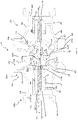
- Figure 1 shows a coupling 10 according to a first embodiment of the present disclosure.
- the coupling 10 has a first body 100 and a second body 200 which can be coupled together to form the coupling 10.
- the first body 100 is formed as a pair of releasably connectable sections comprising a front portion 104 and a rear portion 106.
- the front portion 104 is located proximal to the second body 200 when the first 100 and second 200 bodies are coupled together.
- the rear portion 106 is located distal from the second body 200 when the first 100 and second 200 bodies are coupled together.
- the front 104 and rear 106 portions are connected together via respective fasteners (as shall be described in greater detail below).
- the first body 100 has a first flow path 102 which extends through the entirety first body 100.
- the first flow path 102 is used to convey product through the coupling 10.
- the front 104 and rear portions 106 of the first body 100 each define respective parts of the first flow path 102.
- the product is typically a comestible product and may be provided in particulate form, fluid form (liquid or gas), or as particles suspended or entrained in a fluid (liquid or gas).
- the rear portion 106 of the first body 100 is substantially conical in shape.
- the rear portion 106 has a first end 106a, which is located distal from the front portion 104.
- the first end 106a features a threaded connection 107 to facilitate connection of the coupling 10 to a corresponding pipe or hose in a product flow line.
- the rear portion 106 also features a second end 106b, located proximal to the front portion 104, having a flange 108.
- the flange 108 comprises a plurality of through holes 109 to facilitate connection of the rear portion 106 to the front portion 104 of the first body 100, and also to the second body 200 of the coupling 10, via respective fasteners.
- a first portion 102a of the first flow path 102 is defined by the rear portion 106 of the first body 100.
- the first portion 102a of the first flow path 102 is located distal from the second body 200.
- the first portion 102a of the first flow path 102 is oriented substantially parallel to a longitudinal axis (X) of the coupling 10.
- a second portion 102b of the first flow path 102 is also defined by the rear portion 106 of the first body 100.
- the second portion 102b of the first flow path 102 is located proximal to the second body 200 of the coupling 10.
- the walls of the rear portion 106, which extend around the second portion 102b of the flow path 102, are outwardly tapered such that the diameter of the first flow path 102 increases as you move along the second portion 102b of the flow path towards the second body 200.
- the first flow path 102 reaches a maximum diameter at a point proximal to the flange 108. This helps to improve the flow capacity of the coupling 10.
- the front portion 104 is provided as an annular element having an aperture extending through its centre.
- the aperture of the front portion 104 defines a third portion 102c of the first flow path 102.
- the front portion 104 features a sealing portion 104a and a flange portion 104b.
- the sealing portion 104a is the foremost part of the front portion 104 and is located proximal to the second body 200 of the coupling 10.
- the flange portion 104b is the rearmost part of the front portion 104 and is located distal from the second body 200.
- the walls of the sealing portion 104a which extend around the third portion 102c of the first flow path 102, are inwardly tapered such that the diameter of the first flow path 102 decreases as you move along the third portion 102c of the flow path towards the second body 200.
- the inwardly tapered walls of the sealing portion 104a define an angled seal surface 128 which cooperates with a corresponding valve member during use to prevent the passage of product through the first flow path, as will be described in greater detail below.
- the flange portion 104b is configured to interface with the corresponding flange 108 provided on the rear portion 106 of the first body 100.
- the flange portion 104b has threaded holes 105a to facilitate fastening of the front portion 104 to the rear portion 106.
- the flange portion 104b also has through-holes 105b to facilitate fastening of the first body 100 to the second body 200 as will be described in greater detail at a later stage of this application.
- connection between the front 104 and rear 106 portions of the first body 100 is shown in greater detail in Figure 3 .
- fasteners 110 in this case threaded bolts
- Washers 111 may also be used in conjunction with the fastener 110 to help keep the fasteners 110 from loosening.
- Forming the first body 100 as a pair of separable parts allows the internal components of the coupling 10 to be more easily inserted into the first body 100 during assembly.
- the first body may alternatively be provided as a single component rather than as separable parts.
- a first body seal 112 is provided in a respective groove formed between the front 104 and rear 106 portions of the first body 100.
- the first body seal 112 is an annular seal.
- the first body seal 112 is provided outboard of the first flow path 102 for creating a seal between the front 104 and rear 106 portions.
- the provision of an annular seal between the front 104 and rear 106 portions helps to prevent direct contact between the components of the first body 100 during use.
- the first body seal 112 prevent metal-to-metal contact between the front 104 and rear 106 portions of the first body 100 inboard of the first body seal 112. This helps to better prevent ingress of product into difficult to clean spaces between the front 104 and rear 106 portions which is detrimental to hygiene as trapped products can harbour bacteria.
- a more hygienic coupling can be provided.
- the first body portion 100 has a first valve member 120.
- the first valve member 120 is located within the first body portion 100.
- the first valve member 120 is made up of a valve head 122, a valve body 124 and a valve head seal 126 located between the valve head 122 and the valve body 124.
- the valve head 122 and valve body 124 are connected via a fastener 125.
- the valve head 122, valve body 124 and valve head seal 126 are provided as separate components. However, it shall be appreciated that in other embodiments, one or more of these features may be combined into a single component.
- the valve body 124 has a first portion, proximal to the valve head 122, which forms a seat 124a for the valve head 122.
- the valve body 124 also has a second portion 124b located distal from the valve head 122.
- the first portion 124a of the valve body 124 has an inverted conical shape.
- the valve head 122 is substantially conical in shape.
- the valve head 122 has a front portion 122a of the valve head 122 extends out of the first body 100 when the valve member 120 is in the closed position and a rear portion 122b located proximal to the valve body 124.
- the front portion 122a features an interface surface which cooperates with a corresponding interface surface provided on the second body 200 when the first 100 and second bodies 200 are coupled together to form the coupling 10.
- the interface surface of the valve head 122 comprises a slot 122C which is shaped for locating with a corresponding projection provided on the second body 200 of the coupling 10 (as shall be described in greater detail at a later stage within this application).
- the valve head 122 also features a bore 123 having a threaded surface for receiving a fastener when the first 100 and second bodies 200 are coupled together to form the coupling 10.
- the bore 123 extends from an opening located at the slot 122C, through the valve head 122.
- the threaded surface terminates midway through the depth of the valve head 122.
- the rear portion 122b of the valve head 122 sits on the valve seat 124a.
- the rear portion 122b of the valve head 122 also features a projection 122D which extends into a corresponding recess 124D provided in the valve body 124 to help facilitate connection between the valve head 122 and the valve body 124.
- a washer such as a 16mm wedge-locking washer manufactured by Nord-Lock GmbH may also be provided between the projection 122D of the valve head 122 and the corresponding recess 124D of the valve body 124.
- the valve head seal 126 is an annular seal provided in a respective groove formed between the seat 124a of the valve body 124 and the rear portion 122b of the valve head 122.
- the groove for the annular valve head seal 126 is provided at the outermost extremity of the valve head 122.
- the front portion 104 of the first body 100 has an angled seal surface 128 which reduces the diameter of the flow path 102 passing through the front portion 104 to a point at which the diameter of the flow path 102 is less than a diameter of the first valve member 120.
- the annular valve head seal 126 abuts against the angled seal surface 128 of the front portion 104 of the first body 100.
- the angled seal surface 128 is located outboard of the first product flow path 102 and so, when the annular valve head seal 126 contacts the angled seal surface 128, the passage of product through the first product flow path 102 is prevented.
- the annular valve head seal 126 is the only point of contact between the valve head and the annular seal surface. This helps to prevent wear between the valve head and annular seal surface and also helps to better prevent egress of product between the valve head and the annular seal surface when the valve member is in the closed position.
- the second portion 124b of the valve body 124 is substantially cylindrical in shape and is housed within a first chamber 130 provided within the first body 100.
- the first chamber is integrally formed with the rear portion 106 of the first body 100.
- the first chamber 130 may be provided as a separate component.
- the first chamber 130 is provided as a cylinder located centrally within the first body 100.
- the first flow path 102 extends around a circumference of the first chamber 130.
- a cylinder seal 132 is provided between the interior walls of the first chamber 130 and an exterior of the second portion 124b of the valve body 124 such that the first chamber 130 is sealed against product ingress.
- the first chamber 130 is secured within the first body 100 by supporting arms 138 which extend between the rear portion 106 of the first body 100 and an exterior surface of the first chamber 130.
- the first flow path 102 is provided in three segments (not shown) extending between each of the supporting arms 138 with each segment extending around a portion of the circumference of the first chamber 130.
- the supporting arms are integrally formed with the rear portion 106 of the first body.
- the supporting arms may be provided as separate components.
- the second end 124b of the valve body 124 acts as a piston within the first chamber 130.
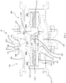
- the first valve member 120 is subsequently actuated between the closed position shown in Figure 1 , in which the annular valve head seal 126 is in contact with the angled seal surface 128, and the open position shown in Figure 3 , in which the annular valve head seal 126 is located substantially coplanar with the annular first body seal 112 such that product is able to pass through the first flow path 102.
- the second portion 124b of the valve body 124 also includes an internal bore 124c which is sealed against product ingress by the respective seals 126, 132 between the valve head 122 and valve body 124 and between the valve body 124 and the first chamber 130 respectively.
- the internal bore 124c is open ended and has a first end proximal to the valve head 122 and a second end proximal to the first chamber 130.
- the coupling 10 has first closure mechanism comprising a first biasing member 150.
- the first biasing member is a coil spring.
- the first biasing member 150 has a first end which is in operable communication with the valve head 122 and a second end which abuts against a base 134 of the first chamber 130.
- the first biasing member 150 is housed within the sealed chamber 130 and within the internal bore 124c of the valve member 120, both of which are sealed against the ingress of product. The first biasing member 150 is therefore isolated from any product passing through the coupling.
- the internal bore 124c may be omitted and the biasing member may alternatively be provided between an end of the valve body and the base of the first chamber.
- the first biasing member 150 becomes compressed between the valve member 120 and the base 134 of the first chamber 130.
- the valve member 120 is therefore biased into the closed position. This means that should the first 100 and second 200 bodies become detached, and hence the compressive force acting on the first biasing member 150 be removed, the first biasing member 150 will return to its original state causing the valve member 120 to be returned to the closed position. This mechanism allows the valve member 120 to self-close.
- a gasket 136 is provided at the base 134 of the first chamber 130.
- the gasket is typically made from a polymeric material such as rubber.
- the gasket 136 acts as a buffer between the second portion 124b of the valve body 124 and the base 134 of the first chamber 130 to help prevent metal-to-metal contact between the components which could lead to wear.
- the gasket 136 also acts as a damper to help prevent unwanted levels of vibration acting of the coupling 10 which could cause unwanted movement of the valve member(s) during use.
- a first test port 140 is provided in the first body 100 of the coupling 10.
- the first test port 140 extends through the first body 100 and has a first end which is in fluid communication with the first chamber 130 and a second end which is in fluid communication with the external atmosphere.
- the first test port 140 is provided such that any product or fluid present within the first chamber 130 can be quickly identified.
- the first chamber 130 and first test port 140 together for a first leakage flow path extending from the cylinder seal 132 to the second end of the first test port 140.
- any fluid or product will be conveyed to the first test portion 140 where it can be easily detected.
- a leakage groove 142 may also be provided in the first test port 140.
- the leakage groove 142 is located proximal to the first end of the first test port 140.
- the leakage groove 142 is arranged to convey any product located in the first chamber 130 to the first test port 140 so that any leakages can be quickly and easily detected via the first port 140.
- the coupling 10 further comprises a pressure sensor 160 which is located proximal to the second end of the test port.
- the pressure sensor 160 is configured to detect the presence of product within the first chamber 130.
- other such sensors may be used for this purpose or the first test port 140 may be inspected manually.
- the sensor may be provided at other locations, such as within the first chamber, rather than proximal to the second end of the test port.
- An internal channel 127 may also be provided within the valve member 120.
- the internal channel 127 shown in the illustrated embodiment comprises two passageways 127a, 127b which, together with the internal bore 124c form the internal channel 127.
- the first passageway 127a is oriented substantially parallel to the longitudinal (X) axis of the coupling 10.
- the first passageway 127a has a first end in fluid communication with the threaded bore 123 and extends from a mid-depth of the valve head 122 through to a second end located at the rear portion 122b of the valve head 122.
- the second end of the first passageway 127a is in fluid communication with the internal bore 124c of the valve body 124.
- the second passageway 127b is orientated substantially perpendicular to the longitudinal (X) axis of the coupling 10.
- the second passageway 127b has a first end proximal to the annular valve head seal 126 and extends through the valve head 122 to a second end which is in fluid communication with the first passageway 127a.
- the first 127a and second 127b passageways are oriented substantially perpendicular to one another.
- the first and second passageways may be oriented differently.
- the first 127a and second 127b passageways of the internal channel 127 and the internal bore 124c together form an second leakage flow path extending from the annular valve head seal 126 to the first chamber 130 of the coupling 10.
- any product or fluid that seeps into the valve member 120 arrangement will be communicated into the first chamber 130 where it can be quickly and easily identified via the test port 140. In this manner, the integrity of the sealing at the valve head seal 126 can be monitored whilst the coupling is in use.
- the first passageway 127a of the internal channel 127 and the internal bore 124c together also form a third leakage flow path extending from the threaded bore 123 of the valve head 122 to the first chamber 130 of the coupling 10. Therefore, in the event that a fluid-tight connection is not achieved between the first and second valve members, any product that seeps into the space between the two valve members will similarly be communicated into the first chamber 130 where it can be quickly and easily identified via the test port 140.. In this manner, the integrity of the sealing between the first and second valve members can also be monitored whilst the coupling is in use.
- the second body 200 also has a respective second flow path 202 extending therethrough for conveying product through the coupling 10.
- the first 102 and second 202 flow paths form a continuous flow path which extends through the coupling 10.
- the second body 200 of the coupling 10 is substantially identical to the first body 100 and so, for the sake of conciseness, only the differences and interoperation between the respective bodies shall be described herein below.
- Like features present on the second body are denoted with like reference numerals having the prefix "2XX" rather than "1XX”.
- the first 100 and second 200 bodies each define corresponding interfaces 100a, 200a which are brought together to form the coupling 10.
- Each of the respective interfaces 100a, 200a defines a plane.
- a portion of the valve head 122 of the first body 100 extends out of the first body 100 when the valve member 120 is in the closed position.
- the front portion 122a of the valve head 122 extends beyond the plane defined by the interface 100a.
- a portion of the valve head 222 of the second body 200 also extends out of the second body 200 when the second valve member 220 is in the closed position.
- the front portion 222a of the valve head 222 also extends beyond the plane defined by the interface 200a.
- the front portion 222a of the second valve member 220 features an interface surface which cooperates with a corresponding interface surface provided on the first valve member 120 when the first 100 and second bodies 200 are coupled together to form the coupling 10.
- the interface surface of the second valve head 222 features a projection 222E which locates within the slot 122C provided on the first body 100 as the first 100 and second bodies 200 are brought together.
- the first body is provided with a slot and the second body is provided with a projection
- the second body may be provided with a slot and the first body may be provided with a projection or, in further alternatives, a different type of interconnection may be used.
- the coupling 10 is configured to switch from the closed position to the open position when the first 100 and second bodies 200 are brought together.
- the front portions 122a, 222a of the respective valve members 120, 220 which project beyond the interfaces 100a, 200a will begin to cooperate and apply a force onto one another.
- This force causes the first 120 and second 220 valve members to move from the closed position (see Figure 1 ) to the open position (see Figure 3 ) without the need for an opening handle or lever.
- valve members 120, 220 are moved from the closed position to the opening position, the respective annular head seals 126, 226 are moved out of contact with the respective angled seal surfaces 128, 228 of the first 100 and second 200 bodies to a position in which the annular valve head seals 126, 226 are located substantially coplanar with the annular first 112 and second 212 body seals.
- the valve members 120, 220 in the open position product is able to pass through the first 102 and second 202 flow paths, and hence through the coupling 10 (see Figure 3 ).
- first 120 and second 220 valve members As the first 120 and second 220 valve members are moved from the closed position to the open position, the respective first 150 and second 250 biasing members become compressed between the respective valve heads 122, 222 and the respective bases 134, 234 of the first 130 and second 230 chambers.
- the valve members 120, 220 are therefore biased into the closed position. This means that should the first 100 and second 200 bodies become detached, and hence the compressive force acting on the first and second biasing members 150, 250 be removed, the first and second biasing members 150,250 will return to their original state causing the valve members 120,220 to be returned to the closed position. In other words, in the event of the first 100 and second 200 bodies becoming decoupled from one another, the valve members 120,220 will self-close, thereby helping to minimise any potential spillages.
- first and second biasing members 150, 250 remain under load. As such, the first and second biasing members 150, 250 continue to apply a force onto the first and second valve members 120, 220 so as to urge the annular valve head seals 126, 226 against the respective seal surfaces 128, 228 when the first and second valve members 120, 220 are in the closed position. This helps to ensure that the respective seals 126, 226 remain compressed when the valve is in the closed position to help further minimise any leakages at the first and second valve heads 122, 222.
- a valve sealing element 300 is provided between the interface surfaces of the first 120 and second 220 valve members which helps to prevent direct contact between the valve members outboard of the valve sealing element 300. This helps to further reduce the likelihood of leakage due to valve wear. Furthermore, by preventing metal-to-metal contact between the cooperating valve members outboard of the valve sealing element, the coupling is able to better product becoming trapped in difficult to clean spaces between the valve members which would be detrimental to hygiene.
- valve seal element 300 is an annular valve seal element 300 provided within a corresponding groove located on the first valve member 120.
- the valve seal element may be provided in a groove on the second valve member 220.
- An interior fastener 310 is also provided for compressing the valve sealing element 300 between the first 120 and second 220 valve members.
- the interior fastener 310 is provided as a frangible bolt having a head 310a and a shank 310b which is configured to break upon the application of a pre-determined amount of force, typically between 5,000 N to 30,000 N depending on the application.
- the provision of a frangible bolt helps to limit that amount of force that can be applied to components in the flow line via the coupling which, in turn helps to prevent damage to the flow line during installation and use which could lead to possible spillages.
- the respective biasing forces provided by the first and second biasing members 150, 250 may be enough to provide sufficient compression of the valve sealing element 300 and so, in some embodiments, the interior fastener 310 may be omitted.
- the second valve member 220 features a corresponding slot 229 which extends through the valve member 220 to the threaded bore 223 to allow for insertion of the interior fastener 310.
- the shank 310b of the interior fastener 310 extends through the threaded bore 223 in the second valve member 220 and into the threaded bore 123 of the first valve member 120 as is shown in Figure 3 .
- the slot 229 is sized so as to receive a head 310a of the fastener 310.
- the slot 229 also features a shoulder portion 229a which prevents the head 310a of the fastener 310 from translating along the respective bores 123, 223.
- the fastener 310 As such, as the fastener 310 is rotated within the threaded bores 123, 223, the fastener 310 will become tensioned, thereby clamping the first 120 and second valve members 220 together. This clamping force compresses the valve sealing element 300 located between the interface surfaces of the valve members 120, 220.
- An annular seal 320 is provided between the respective interfaces 100a, 200a of the first and second bodies 100, 200, outboard of the flow path, for creating a seal between the first 100 and second 200 bodies.
- the coupling 10 is configured such that metal-to-metal contact between the respective first and second bodies 100, 200 inboard of the annular seal 320 is prevented.
- the annular seal 320 is provided within a corresponding groove located in the second body 200.
- the annular seal 320 may be provided in a groove in the first body 100 or may simply be applied during installation.
- Exterior fasteners 330 are also provided to compress the annular seal 320 between the first 100 and second bodies 200 once they have been brought together to form the coupling 10 as shown in Figure 4 .
- the exterior fasteners 330 are frangible bolts having a head 332 and a shank 334.
- the exterior fasteners 330 also feature a frangible portion 336 which is machined into the shank 334.
- the frangible portion 336 is machined to a diameter such that the exterior fastener 330 will break upon the application of a pre-determined amount of force.
- the respective shanks 334 of the exterior fasteners 330 inserted through the respective through holes 105b, 205b, 109, 209 provided in the respective flanges 104b, 108, 204b, 208 of the first 100 and second 200 bodies.
- the respective heads 332 of the exterior fasteners 330 abut against an outer surface of the rear portion 206 of the second body 200.
- the respective through holes 105b provided in the first body 100 have a threaded internal surface for cooperating with a corresponding thread provided on an end of the exterior fastener 330. Therefore, as the exterior fasteners 330 are rotated, they will become tensioned, thereby clamping the first 100 and second 200 bodies together. This clamping force compresses the annular seal 320 located between the interface surfaces 100a, 200a of the first 100 and second 200 bodies. Washers 338 may also be used in conjunction with the fasteners 330 to help keep the fasteners 330 from loosening.
- the exterior fasteners 330 comprise a head 332 which abuts the second body 200 and threaded internal surfaces are provided in the through holes of the first body, in other embodiments, the head 332 may abut the first body 100 and the threaded internal surfaces may be provided in the through holes of the second body or, alternatively, a different type of exterior fastener may be used.
- the coupling 10 illustrated in Figures 1 to 4 is primarily designed to be vertically oriented when placed within a given product flow line. However, it shall be appreciated that in other embodiments the coupling 10 may be placed in a horizontal, inclined or declined orientation.
- compositions for human or animal consumption.
- comestible products may be provided in particulate form, fluid form (liquid or gas), or as particles suspended or entrained in a fluid (liquid or gas).
- first and second couplings are substantially identical, it shall be appreciated that in some other embodiments, the first and second coupling may not be identical in form.
Landscapes
- Engineering & Computer Science (AREA)
- General Engineering & Computer Science (AREA)
- Mechanical Engineering (AREA)
- Lift Valve (AREA)
Applications Claiming Priority (1)
| Application Number | Priority Date | Filing Date | Title |
|---|---|---|---|
| GB2106488.6A GB2606388B (en) | 2021-05-06 | 2021-05-06 | Coupling |
Publications (3)
| Publication Number | Publication Date |
|---|---|
| EP4086497A1 true EP4086497A1 (fr) | 2022-11-09 |
| EP4086497C0 EP4086497C0 (fr) | 2024-09-18 |
| EP4086497B1 EP4086497B1 (fr) | 2024-09-18 |
Family
ID=76921037
Family Applications (1)
| Application Number | Title | Priority Date | Filing Date |
|---|---|---|---|
| EP22172041.0A Active EP4086497B1 (fr) | 2021-05-06 | 2022-05-06 | Coupleur |
Country Status (3)
| Country | Link |
|---|---|
| US (1) | US12007050B2 (fr) |
| EP (1) | EP4086497B1 (fr) |
| GB (1) | GB2606388B (fr) |
Families Citing this family (2)
| Publication number | Priority date | Publication date | Assignee | Title |
|---|---|---|---|---|
| DE102021114973A1 (de) * | 2021-06-10 | 2022-12-15 | Norma Germany Gmbh | Ventil für eine Fluidleitung eines Fahrzeugs |
| FR3131949B1 (fr) * | 2022-01-17 | 2023-12-08 | Air Liquide | Dispositif d’accouplement et son procédé de purge |
Citations (5)
| Publication number | Priority date | Publication date | Assignee | Title |
|---|---|---|---|---|
| EP0159984B1 (fr) * | 1982-11-30 | 1989-02-22 | Alpha Process Controls (International) Ltd. | Raccordement detachable pour tuyaux flexibles |
| DE4202491C1 (en) * | 1991-11-28 | 1993-05-06 | Guenter 2050 Boernsen De Rathje | Tear-off coupling for liq. or gas pipelines - has flanges with breakable elements and valve discs spring-loaded to close off pipe ends |
| US6082401A (en) * | 1995-01-06 | 2000-07-04 | Colder Products Company | Low spill high flow quick coupling valve assembly |
| GB2575539A (en) | 2018-05-16 | 2020-01-15 | Alpha Process Controls International Ltd | A coupling |
| KR20200028683A (ko) * | 2018-09-07 | 2020-03-17 | 주식회사 코밸 | 비상상태 해제 커플링 구조 |
Family Cites Families (21)
| Publication number | Priority date | Publication date | Assignee | Title |
|---|---|---|---|---|
| US2304390A (en) * | 1940-11-14 | 1942-12-08 | Arthur L Parker | Coupling |
| US2319015A (en) * | 1941-02-11 | 1943-05-11 | Cleveland Pneumatic Tool Co | Valve coupling |
| US2451218A (en) * | 1946-07-13 | 1948-10-12 | Bendix Aviat Corp | Quick disconnect coupling |
| US2931668A (en) * | 1956-04-30 | 1960-04-05 | Bastian Blessing Co | Coupling |
| US3213884A (en) * | 1963-01-23 | 1965-10-26 | Int Harvester Co | Self-sealing coupling and directional valve |
| US3446245A (en) * | 1966-02-28 | 1969-05-27 | Srm Co | Threaded fluid coupling |
| US3478762A (en) * | 1967-03-10 | 1969-11-18 | Thiokol Chemical Corp | Coupling and valve assembly |
| US3659877A (en) * | 1970-09-11 | 1972-05-02 | Shell Oil Co | Breakaway pipe coupling |
| US3706318A (en) * | 1971-03-02 | 1972-12-19 | Fairchild Industries | Fluid coupling |
| US4287914A (en) * | 1980-01-16 | 1981-09-08 | Aeroquip Corporation | Self sealing coupling with full flow relief valve |
| DE3439876A1 (de) * | 1983-11-02 | 1985-05-15 | Daikin Industries, Ltd., Osaka | Korrosionsbestaendige schnelloesekupplungsvorrichtung |
| GB9217591D0 (en) * | 1992-08-19 | 1992-09-30 | Rawlins Graham C | Improvements in or relating to couplings |
| US5407175A (en) * | 1994-04-15 | 1995-04-18 | Emco Wheaton, Inc. | Flow valve having rotatable annular flange |
| DE4430132C1 (de) * | 1994-08-25 | 1995-09-28 | Guenter Rathje | Abreißkupplung |
| MY120016A (en) * | 1997-01-23 | 2005-08-30 | Kyoseki Sangyo Co Ltd | Self-seal type double-pipe joint |
| FR2780483B1 (fr) * | 1998-06-30 | 2000-08-25 | Staubli Sa Ets | Coupe-circuit pour installation de manutention de fluide sous pression |
| SE0303359D0 (sv) * | 2003-12-10 | 2003-12-10 | Maquet Critical Care Ab | Kopplingssystem |
| DE102011111790A1 (de) * | 2011-09-01 | 2013-03-07 | Meco Eckel Gmbh | Kupplung für ein Hydraulik- oder Pneumatiksystem |
| NO342434B1 (en) * | 2016-06-16 | 2018-05-22 | Fmc Kongsberg Subsea As | Poppet coupling |
| KR101949323B1 (ko) * | 2017-03-27 | 2019-02-18 | 디케이락 주식회사 | 브레이크어웨이 커플링용 케이싱 및 브레이킹 볼트 |
| DE102017005588A1 (de) * | 2017-06-13 | 2018-12-13 | Messer France S.A.S. | Kupplung für tiefkalte verflüssigte Medien |
-
2021
- 2021-05-06 GB GB2106488.6A patent/GB2606388B/en active Active
-
2022
- 2022-05-06 US US17/738,716 patent/US12007050B2/en active Active
- 2022-05-06 EP EP22172041.0A patent/EP4086497B1/fr active Active
Patent Citations (5)
| Publication number | Priority date | Publication date | Assignee | Title |
|---|---|---|---|---|
| EP0159984B1 (fr) * | 1982-11-30 | 1989-02-22 | Alpha Process Controls (International) Ltd. | Raccordement detachable pour tuyaux flexibles |
| DE4202491C1 (en) * | 1991-11-28 | 1993-05-06 | Guenter 2050 Boernsen De Rathje | Tear-off coupling for liq. or gas pipelines - has flanges with breakable elements and valve discs spring-loaded to close off pipe ends |
| US6082401A (en) * | 1995-01-06 | 2000-07-04 | Colder Products Company | Low spill high flow quick coupling valve assembly |
| GB2575539A (en) | 2018-05-16 | 2020-01-15 | Alpha Process Controls International Ltd | A coupling |
| KR20200028683A (ko) * | 2018-09-07 | 2020-03-17 | 주식회사 코밸 | 비상상태 해제 커플링 구조 |
Also Published As
| Publication number | Publication date |
|---|---|
| EP4086497C0 (fr) | 2024-09-18 |
| GB2606388A (en) | 2022-11-09 |
| US20220356972A1 (en) | 2022-11-10 |
| US12007050B2 (en) | 2024-06-11 |
| GB2606388B (en) | 2024-02-28 |
| EP4086497B1 (fr) | 2024-09-18 |
Similar Documents
| Publication | Publication Date | Title |
|---|---|---|
| EP4086497A1 (fr) | Coupleur | |
| US6916007B2 (en) | Closure valve apparatus for fluid dispensing | |
| CA2029298C (fr) | Joint d'etancheite de raccord pour montage aseptique | |
| AU685244B2 (en) | Undersea hydraulic coupling with metal seals | |
| US4570665A (en) | Aseptic valve with unitary valve seat and lip seals | |
| US5199683A (en) | Blowout preventer opening mechanism | |
| US5299598A (en) | Check valve | |
| GB2248281A (en) | Hydraulic coupling with pressurised metal seal | |
| WO2003093705A1 (fr) | Ensemble vanne a bille | |
| JPH0854089A (ja) | 安全弁付パイプ迅速連結具 | |
| JPH01503476A (ja) | 急速ストレート連結流体用カツプラ | |
| US20170089485A1 (en) | Valve | |
| JPH0137635B2 (fr) | ||
| US7681927B2 (en) | Low pressure fitting | |
| US20100193722A1 (en) | Retractable Seal Ball Valve | |
| US6976664B2 (en) | Free flow valve and element | |
| US8602045B2 (en) | Clean-in-place valve assembly and method of operation | |
| US12085179B2 (en) | Safety valve | |
| US6520426B2 (en) | Sanitary spray nozzle for spray guns | |
| EP1411282A1 (fr) | Joint rotatif d'un robinet à tournant sphérique | |
| US5439024A (en) | Sanitary gate valve with tapered valve plug | |
| US6460899B1 (en) | Disconnect coupling | |
| US6123104A (en) | Undersea hydraulic coupling with Y-seal | |
| US6149127A (en) | Spring loaded compression valve fitting | |
| US5509698A (en) | Axially extendible conduit |
Legal Events
| Date | Code | Title | Description |
|---|---|---|---|
| PUAI | Public reference made under article 153(3) epc to a published international application that has entered the european phase |
Free format text: ORIGINAL CODE: 0009012 |
|
| STAA | Information on the status of an ep patent application or granted ep patent |
Free format text: STATUS: THE APPLICATION HAS BEEN PUBLISHED |
|
| AK | Designated contracting states |
Kind code of ref document: A1 Designated state(s): AL AT BE BG CH CY CZ DE DK EE ES FI FR GB GR HR HU IE IS IT LI LT LU LV MC MK MT NL NO PL PT RO RS SE SI SK SM TR |
|
| STAA | Information on the status of an ep patent application or granted ep patent |
Free format text: STATUS: REQUEST FOR EXAMINATION WAS MADE |
|
| 17P | Request for examination filed |
Effective date: 20230509 |
|
| RBV | Designated contracting states (corrected) |
Designated state(s): AL AT BE BG CH CY CZ DE DK EE ES FI FR GB GR HR HU IE IS IT LI LT LU LV MC MK MT NL NO PL PT RO RS SE SI SK SM TR |
|
| STAA | Information on the status of an ep patent application or granted ep patent |
Free format text: STATUS: EXAMINATION IS IN PROGRESS |
|
| 17Q | First examination report despatched |
Effective date: 20231215 |
|
| GRAP | Despatch of communication of intention to grant a patent |
Free format text: ORIGINAL CODE: EPIDOSNIGR1 |
|
| STAA | Information on the status of an ep patent application or granted ep patent |
Free format text: STATUS: GRANT OF PATENT IS INTENDED |
|
| RIC1 | Information provided on ipc code assigned before grant |
Ipc: F16L 23/036 20060101ALN20240522BHEP Ipc: F16L 55/10 20060101ALI20240522BHEP Ipc: F16L 29/04 20060101AFI20240522BHEP |
|
| RIC1 | Information provided on ipc code assigned before grant |
Ipc: F16L 23/036 20060101ALN20240529BHEP Ipc: F16L 55/10 20060101ALI20240529BHEP Ipc: F16L 29/04 20060101AFI20240529BHEP |
|
| INTG | Intention to grant announced |
Effective date: 20240613 |
|
| RIC1 | Information provided on ipc code assigned before grant |
Ipc: F16L 23/036 20060101ALN20240603BHEP Ipc: F16L 55/10 20060101ALI20240603BHEP Ipc: F16L 29/04 20060101AFI20240603BHEP |
|
| GRAS | Grant fee paid |
Free format text: ORIGINAL CODE: EPIDOSNIGR3 |
|
| GRAA | (expected) grant |
Free format text: ORIGINAL CODE: 0009210 |
|
| STAA | Information on the status of an ep patent application or granted ep patent |
Free format text: STATUS: THE PATENT HAS BEEN GRANTED |
|
| AK | Designated contracting states |
Kind code of ref document: B1 Designated state(s): AL AT BE BG CH CY CZ DE DK EE ES FI FR GB GR HR HU IE IS IT LI LT LU LV MC MK MT NL NO PL PT RO RS SE SI SK SM TR |
|
| REG | Reference to a national code |
Ref country code: GB Ref legal event code: FG4D |
|
| REG | Reference to a national code |
Ref country code: CH Ref legal event code: EP |
|
| REG | Reference to a national code |
Ref country code: DE Ref legal event code: R096 Ref document number: 602022006134 Country of ref document: DE |
|
| REG | Reference to a national code |
Ref country code: IE Ref legal event code: FG4D |
|
| U01 | Request for unitary effect filed |
Effective date: 20241016 |
|
| U07 | Unitary effect registered |
Designated state(s): AT BE BG DE DK EE FI FR IT LT LU LV MT NL PT RO SE SI Effective date: 20241031 |
|
| PG25 | Lapsed in a contracting state [announced via postgrant information from national office to epo] |
Ref country code: NO Free format text: LAPSE BECAUSE OF FAILURE TO SUBMIT A TRANSLATION OF THE DESCRIPTION OR TO PAY THE FEE WITHIN THE PRESCRIBED TIME-LIMIT Effective date: 20241218 |
|
| PG25 | Lapsed in a contracting state [announced via postgrant information from national office to epo] |
Ref country code: GR Free format text: LAPSE BECAUSE OF FAILURE TO SUBMIT A TRANSLATION OF THE DESCRIPTION OR TO PAY THE FEE WITHIN THE PRESCRIBED TIME-LIMIT Effective date: 20241219 |
|
| PG25 | Lapsed in a contracting state [announced via postgrant information from national office to epo] |
Ref country code: HR Free format text: LAPSE BECAUSE OF FAILURE TO SUBMIT A TRANSLATION OF THE DESCRIPTION OR TO PAY THE FEE WITHIN THE PRESCRIBED TIME-LIMIT Effective date: 20240918 |
|
| PG25 | Lapsed in a contracting state [announced via postgrant information from national office to epo] |
Ref country code: RS Free format text: LAPSE BECAUSE OF FAILURE TO SUBMIT A TRANSLATION OF THE DESCRIPTION OR TO PAY THE FEE WITHIN THE PRESCRIBED TIME-LIMIT Effective date: 20241218 |
|
| PG25 | Lapsed in a contracting state [announced via postgrant information from national office to epo] |
Ref country code: RS Free format text: LAPSE BECAUSE OF FAILURE TO SUBMIT A TRANSLATION OF THE DESCRIPTION OR TO PAY THE FEE WITHIN THE PRESCRIBED TIME-LIMIT Effective date: 20241218 Ref country code: NO Free format text: LAPSE BECAUSE OF FAILURE TO SUBMIT A TRANSLATION OF THE DESCRIPTION OR TO PAY THE FEE WITHIN THE PRESCRIBED TIME-LIMIT Effective date: 20241218 Ref country code: HR Free format text: LAPSE BECAUSE OF FAILURE TO SUBMIT A TRANSLATION OF THE DESCRIPTION OR TO PAY THE FEE WITHIN THE PRESCRIBED TIME-LIMIT Effective date: 20240918 Ref country code: GR Free format text: LAPSE BECAUSE OF FAILURE TO SUBMIT A TRANSLATION OF THE DESCRIPTION OR TO PAY THE FEE WITHIN THE PRESCRIBED TIME-LIMIT Effective date: 20241219 |
|
| PG25 | Lapsed in a contracting state [announced via postgrant information from national office to epo] |
Ref country code: IS Free format text: LAPSE BECAUSE OF FAILURE TO SUBMIT A TRANSLATION OF THE DESCRIPTION OR TO PAY THE FEE WITHIN THE PRESCRIBED TIME-LIMIT Effective date: 20250118 |
|
| PG25 | Lapsed in a contracting state [announced via postgrant information from national office to epo] |
Ref country code: SM Free format text: LAPSE BECAUSE OF FAILURE TO SUBMIT A TRANSLATION OF THE DESCRIPTION OR TO PAY THE FEE WITHIN THE PRESCRIBED TIME-LIMIT Effective date: 20240918 |
|
| PG25 | Lapsed in a contracting state [announced via postgrant information from national office to epo] |
Ref country code: ES Free format text: LAPSE BECAUSE OF FAILURE TO SUBMIT A TRANSLATION OF THE DESCRIPTION OR TO PAY THE FEE WITHIN THE PRESCRIBED TIME-LIMIT Effective date: 20240918 |
|
| PG25 | Lapsed in a contracting state [announced via postgrant information from national office to epo] |
Ref country code: CZ Free format text: LAPSE BECAUSE OF FAILURE TO SUBMIT A TRANSLATION OF THE DESCRIPTION OR TO PAY THE FEE WITHIN THE PRESCRIBED TIME-LIMIT Effective date: 20240918 Ref country code: PL Free format text: LAPSE BECAUSE OF FAILURE TO SUBMIT A TRANSLATION OF THE DESCRIPTION OR TO PAY THE FEE WITHIN THE PRESCRIBED TIME-LIMIT Effective date: 20240918 |
|
| PG25 | Lapsed in a contracting state [announced via postgrant information from national office to epo] |
Ref country code: SK Free format text: LAPSE BECAUSE OF FAILURE TO SUBMIT A TRANSLATION OF THE DESCRIPTION OR TO PAY THE FEE WITHIN THE PRESCRIBED TIME-LIMIT Effective date: 20240918 |
|
| PLBE | No opposition filed within time limit |
Free format text: ORIGINAL CODE: 0009261 |
|
| STAA | Information on the status of an ep patent application or granted ep patent |
Free format text: STATUS: NO OPPOSITION FILED WITHIN TIME LIMIT |
|
| U21 | Renewal fee for the european patent with unitary effect paid with additional fee |
Year of fee payment: 4 Effective date: 20250630 |
|
| 26N | No opposition filed |
Effective date: 20250619 |
|
| U1N | Appointed representative for the unitary patent procedure changed after the registration of the unitary effect |
Representative=s name: WITHERS & ROGERS; GB |
|
| REG | Reference to a national code |
Ref country code: CH Ref legal event code: H13 Free format text: ST27 STATUS EVENT CODE: U-0-0-H10-H13 (AS PROVIDED BY THE NATIONAL OFFICE) Effective date: 20251223 |
|
| PG25 | Lapsed in a contracting state [announced via postgrant information from national office to epo] |
Ref country code: CH Free format text: LAPSE BECAUSE OF NON-PAYMENT OF DUE FEES Effective date: 20250531 |
|
| PG25 | Lapsed in a contracting state [announced via postgrant information from national office to epo] |
Ref country code: MC Free format text: LAPSE BECAUSE OF FAILURE TO SUBMIT A TRANSLATION OF THE DESCRIPTION OR TO PAY THE FEE WITHIN THE PRESCRIBED TIME-LIMIT Effective date: 20240918 |
|
| U1N | Appointed representative for the unitary patent procedure changed after the registration of the unitary effect |
Representative=s name: EDSON, RUSSELL GREGORY; GB |
|
| PG25 | Lapsed in a contracting state [announced via postgrant information from national office to epo] |
Ref country code: IE Free format text: LAPSE BECAUSE OF NON-PAYMENT OF DUE FEES Effective date: 20250506 |