EP4086686A1 - Système de microscopie et procédé de fonctionnement d'un système de microscopie - Google Patents
Système de microscopie et procédé de fonctionnement d'un système de microscopie Download PDFInfo
- Publication number
- EP4086686A1 EP4086686A1 EP21216369.5A EP21216369A EP4086686A1 EP 4086686 A1 EP4086686 A1 EP 4086686A1 EP 21216369 A EP21216369 A EP 21216369A EP 4086686 A1 EP4086686 A1 EP 4086686A1
- Authority
- EP
- European Patent Office
- Prior art keywords
- illumination
- image
- tracking
- microscopy system
- working distance
- Prior art date
- Legal status (The legal status is an assumption and is not a legal conclusion. Google has not performed a legal analysis and makes no representation as to the accuracy of the status listed.)
- Withdrawn
Links
- 238000000386 microscopy Methods 0.000 title claims abstract description 85
- 238000000034 method Methods 0.000 title claims abstract description 33
- 238000005286 illumination Methods 0.000 claims abstract description 183
- 238000001514 detection method Methods 0.000 claims description 128
- 230000003287 optical effect Effects 0.000 claims description 106
- 230000007423 decrease Effects 0.000 claims description 9
- 230000000007 visual effect Effects 0.000 claims description 9
- 230000003068 static effect Effects 0.000 claims description 5
- 230000005855 radiation Effects 0.000 description 29
- 239000003550 marker Substances 0.000 description 15
- 238000011156 evaluation Methods 0.000 description 13
- 230000008859 change Effects 0.000 description 10
- 238000003384 imaging method Methods 0.000 description 8
- 230000004913 activation Effects 0.000 description 7
- 239000006059 cover glass Substances 0.000 description 7
- 230000001419 dependent effect Effects 0.000 description 5
- 230000003247 decreasing effect Effects 0.000 description 4
- 150000001875 compounds Chemical class 0.000 description 3
- 238000010586 diagram Methods 0.000 description 3
- 238000007493 shaping process Methods 0.000 description 3
- 230000005540 biological transmission Effects 0.000 description 2
- 238000013461 design Methods 0.000 description 2
- 239000011521 glass Substances 0.000 description 2
- 238000012423 maintenance Methods 0.000 description 2
- 230000009466 transformation Effects 0.000 description 2
- 230000003213 activating effect Effects 0.000 description 1
- 230000006978 adaptation Effects 0.000 description 1
- 238000000149 argon plasma sintering Methods 0.000 description 1
- 230000033228 biological regulation Effects 0.000 description 1
- 210000004556 brain Anatomy 0.000 description 1
- 238000011109 contamination Methods 0.000 description 1
- 238000001816 cooling Methods 0.000 description 1
- 238000011161 development Methods 0.000 description 1
- 230000000694 effects Effects 0.000 description 1
- 230000017525 heat dissipation Effects 0.000 description 1
- 238000004519 manufacturing process Methods 0.000 description 1
- 239000000463 material Substances 0.000 description 1
- 230000008569 process Effects 0.000 description 1
- 238000012545 processing Methods 0.000 description 1
Images


Classifications
-
- G—PHYSICS
- G02—OPTICS
- G02B—OPTICAL ELEMENTS, SYSTEMS OR APPARATUS
- G02B21/00—Microscopes
- G02B21/0004—Microscopes specially adapted for specific applications
- G02B21/0012—Surgical microscopes
-
- G—PHYSICS
- G02—OPTICS
- G02B—OPTICAL ELEMENTS, SYSTEMS OR APPARATUS
- G02B21/00—Microscopes
- G02B21/36—Microscopes arranged for photographic purposes or projection purposes or digital imaging or video purposes including associated control and data processing arrangements
- G02B21/365—Control or image processing arrangements for digital or video microscopes
-
- G—PHYSICS
- G02—OPTICS
- G02B—OPTICAL ELEMENTS, SYSTEMS OR APPARATUS
- G02B27/00—Optical systems or apparatus not provided for by any of the groups G02B1/00 - G02B26/00, G02B30/00
- G02B27/32—Fiducial marks and measuring scales within the optical system
Definitions
- the invention relates to a microscopy system and a method for operating a microscopy system.
- Microscopy systems for the magnified representation of objects to be examined, in particular in medical applications, are known from the prior art.
- Such microscopy systems can in particular be so-called surgical microscopes. These are used, among other things, for the enlarged representation of parts of a body in order to enable a surgeon to have better visual orientation during an intervention.
- Surgical microscopes are generally movably mounted, in particular on a stand. This allows a user, among other things, to change a location, ie a position and/or orientation, of the microscope, for example to change an angle of view of an examination area or to view other examination areas.
- the DE 10 2018 206 406 B3 discloses a microscopy system with a position detection device for detecting a spatial position of a target, wherein the position detection device comprises the at least one target with at least one marker element and an image detection device for optical detection of the target. Furthermore, the document discloses that the microscopy system can include an illumination device for illuminating the target.
- the disclosed position detection device can be used in particular to detect the position of an instrument, for example a medical instrument, when the target is attached to the instrument. Such a position detection can be desirable if, for example, a current position of the instrument relative to preoperatively generated data, for example MRT or CT volume data, is to be displayed.
- EP 21 172 758.1 discloses a microscopy system with a device for determining a working distance, the position of a movable optical element, the position of which can be adjusted for setting a detection range of a tracking camera, being adjustable as a function of the working distance.
- a mode of operation and / or a Illumination range of tracking illumination devices of the microscopy system is/are adjustable depending on the working distance.
- position detection devices external to the microscope, which are arranged, for example, as separate systems in an operating room.
- the optical position detection device from NDI (Northern Digital Inc.) known under the name Polaris Vega VT should be mentioned as an example.
- Such detection devices require extra space in the operating room.
- occlusions for example when a user moves between a target and the image detection devices of such a position detection device. This restricts a range of movement for medical personnel.
- Position detection with such a position detection device also regularly requires a target with at least one marker to also be arranged on the surgical microscope in order to provide desired functionalities.
- Attaching additional targets to the surgical microscope during maintenance generally also requires the disassembly of such targets, which are then reassembled after maintenance and make it necessary to calibrate the position detection device again.
- microscope-external position detection devices require strong illumination, specifically to illuminate areas in the operating room, so that all of the targets of interest, which are arranged, for example, on the patient, on an instrument and on the microscopy system, can be reliably imaged.
- Such systems also require high-resolution image acquisition devices and high computing power for evaluating the images, which is necessary for position acquisition.
- Another disadvantage of such position detection devices is increasing inaccuracy when there are large distances between a target and the image detection devices.
- the technical problem therefore arises of creating a microscopy system and a method for operating this microscopy system which enable reliable and precise position detection and provide improved quality of use.
- the microscopy system includes a microscope.
- a microscope designates a device for the enlarged visual representation of an examination object.
- the microscope can be a classic Be a light microscope, which generates an enlarged image by using optical effects, in particular by means for beam guidance and / or shaping and / or steering, such as lenses.
- the microscope can also be a digital microscope, in which case the image to be visualized by the microscope can be generated by means of an image acquisition device and displayed on a corresponding display device, for example a display.
- the microscope can comprise at least one eyepiece.
- the eyepiece refers to a part of the microscope through which or into which a user looks to visually capture the image produced by the microscope.
- an eyepiece forms an eye-side optical interface of the microscope.
- the eyepiece can form part of a tube.
- the microscope can include at least one objective or an objective system.
- This lens can generate a real optical image of an examination object.
- the lens can comprise optical elements for beam guidance and/or shaping and/or steering.
- the eyepiece can be or will be optically connected to the lens.
- the microscope can include a microscope body.
- the microscope body can have or form a beam path for microscopic imaging.
- the microscope body can comprise further optical elements for beam guidance and/or beam shaping and/or beam deflection.
- the lens can be integrated into the microscope body or attached to it, in particular detachably.
- the microscope body can be arranged stationary relative to the microscope body.
- the microscope body can have or form at least one attachment interface for attachment, in particular for detachable attachment, of a tube.
- the microscope body can comprise or form a housing or be arranged in a housing.
- the microscopy system can also include a stand for holding the microscope.
- the microscope in particular the microscope body, can thus be mechanically fastened to the stand.
- the stand is designed in such a way that it enables movement of the microscope in space, in particular with at least one degree of freedom, preferably with six degrees of freedom, with one degree of freedom being a translational or rotational degree of freedom.
- the degrees of freedom can relate to a reference coordinate system.
- a vertical axis (z-axis) of this reference coordinate system can be oriented parallel to and opposite to the gravitational force.
- a longitudinal axis (x-axis) of the reference coordinate system and a transverse axis (y-axis) of the reference coordinate system can be a plane clamp, which is oriented perpendicular to the vertical axis.
- the longitudinal and transverse axes can also be oriented orthogonally to one another.
- the stand can include at least one drive device for moving the microscope.
- a drive device can be a servo motor, for example.
- the stand can also include means for force/torque transmission, e.g. gear units.
- the at least one drive device can be controlled in such a way that an optical axis of the lens assumes a desired orientation.
- the at least one drive device can be controlled in such a way that a reference point of the microscope, e.g.
- a focus point is positioned at a desired position in space.
- a target position can be specified by a user or another higher-level system.
- Methods for controlling the at least one drive device as a function of a desired position and a kinematic structure of the stand are known to those skilled in the art.
- the microscopy system includes a tracking camera for detecting the position of at least one object to be detected.
- the tracking camera designates an image capturing device for capturing a spatial position of at least one object to be captured.
- the image capture device is used to image the object to be captured.
- the tracking camera can be part of a position detection device of the microscopy system.
- the position detection device can include an evaluation or computing device that can carry out a position determination/detection by evaluating the images generated by the tracking camera.
- the object to be detected can in particular be a marker or marker element.
- the object to be detected can also be an instrument.
- the instrument can in particular be a medical instrument, more particularly a surgical instrument.
- the instrument can in particular be an instrument that can be guided by a user's hand.
- an instrument can be operating room furniture such as an operating table or a Mayfield clamp.
- one or more marker element(s) can be arranged on an instrument.
- the marker or the marker element can be part of a target or attached to a target.
- the target or marker can be attached in particular to a (medical) instrument.
- the position detection device in particular its evaluation device, can identify an object to be detected, in particular image-based, ie using methods of image processing and evaluation that are known to the person skilled in the art.
- the tracking camera includes an image sensor, such as a CCD or CMOS image sensor.
- a resolution of the image sensor can be 12 megapixels, for example.
- the tracking camera can include an optical system with at least one optical element.
- the position detection can also be used for position tracking, ie the determination of the position at several consecutive points in time.
- a so-called monoscopic position detection can be carried out by means of the tracking camera.
- the position can be determined by evaluating a two-dimensional image, in particular precisely a two-dimensional image.
- the tracking camera can be part of a position detection device which, in addition to the tracking camera, can also include an evaluation device for determining the position in a predetermined reference coordinate system.
- the location designates a spatial position and/or a spatial orientation in the reference coordinate system.
- an evaluation of intensity values of pixels of the two-dimensional image can be carried out to determine the position.
- Such methods for image-based position detection with precisely one tracking camera or multiple tracking cameras are known to those skilled in the art.
- the microscopy system comprises at least one, but preferably at least two, tracking illumination device(s).
- a tracking lighting device designates a lighting device for illuminating or illuminating a detection area of the at least one tracking camera.
- the microscopy system can comprise at least one optical element, in particular designed as a lens, for guiding the radiation generated by the tracking illumination device(s) and at least one control device for controlling the tracking illumination device and/or for controlling the tracking camera.
- a computing device can be in the form of a microcontroller or an integrated circuit or can include one(s).
- the computing device can in particular be formed by a control device of the microscopy system or be part of it.
- the microscopy system can include a computing device for image evaluation, for position determination and for setting the illumination.
- An illumination area can therefore be defined by the at least one optical element.
- a tracking lighting device can be designed in particular as an LED.
- a tracking illumination device can generate light in the near infrared range, preferably in a narrow-band wavelength range, for example with a wavelength of 850 nm or with a wavelength from a range of 800 nm to 900 nm.
- the object to be detected can be formed at least partially or completely from a material that reflects this radiation.
- the control device can be used to control an operating mode, in particular an activation state and/or an intensity of the generated radiation, and/or to set an illumination area of a tracking illumination device.
- An illumination area in particular its size and/or shape, can also be set by the illumination area.
- An activation state can be “not active”, for example, with no radiation being generated by the tracking illumination device in this state.
- a further activation state can be "active", radiation being generated by the tracking lighting device in this activation state.
- the intensity can be adjusted in the active state.
- an illumination angle, a size and/or a geometric shape of the illumination area can be adjusted, for example by controlling at least one or more optical element(s) to adjust the variables mentioned.
- an optical element for beam guidance of the radiation generated by a tracking lighting device is a movable and/or deformable optical element, with a position and/or a shape of this optical element for setting different lighting areas and/or for setting different lighting states in different spatial areas can be changed.
- an optical element can be an element designed in accordance with a movable optical element for setting the detection range of the tracking camera.
- the illumination angle can be an emission angle of the illumination device. This in turn can correspond to the aperture angle of a conical illumination area.
- different spatial areas are area-specific, in particular independently of one another, for example with different illumination parameters such as an intensity and/or an illumination angle the tracking lighting devices can be illuminated. This can be done by adjusting the position and/or the shape of at least one optical element, but alternatively or cumulatively also by controlling the mode of operation and/or adjusting the lighting area.
- lighting information can be determined or is determined by evaluating at least one image of the tracking camera.
- position information of the object relative to at least one lighting device ie information about a position of the object relative to the lighting device, can be determined or is determined. This determination can be made by the control device explained or by a different evaluation device, which, however, can also be designed as a computing device. Further alternatively or cumulatively, a working distance can be determined or is determined. This is explained in more detail below.
- the illumination in other words an illumination state, by the at least one tracking illumination device and/or the image acquisition, in other words an image acquisition state, by the at least one tracking camera is dependent on the illumination information and/or the position information of the object and/or dependent of the working distance
- the lighting can be set, for example, by the explained setting of the mode of operation and/or the lighting range of the at least one tracking lighting device, in particular by setting lighting parameters.
- the illumination can also be adjustable by adjusting the position and/or the shape of an optical element explained.
- the image capture can be set in particular by setting an operating mode of the at least one tracking camera, in particular by setting an image capture parameter such as an exposure time.
- the lighting information can in particular be brightness information, ie information about the brightness of the image or a partial area of the image.
- the information can be a brightness value, for example.
- the image brightness can be determined as the mean value of the pixel intensities in the image or part of the image.
- a pixel intensity can be a gray value intensity.
- image brightness may be determined as the average of pixel intensities representing the brightness of a pixel in a brightness-chroma model, such as the YCbCr model. To do this, it may be necessary to transform the color image into a representation based on the lightness-colorfulness model mentioned.
- the brightness of a pixel can also be determined as a function of the intensity in each of the color channels assigned to the pixels, for example as the mean value of these color-channel-specific intensities.
- the lighting can be changed in such a way that the brightness value is reduced, for example by reducing the overall intensity of the radiation generated by the at least one tracking lighting device.
- the lighting can be changed in such a way that the brightness value is increased, for example by increasing the total intensity of the radiation generated by the at least one tracking lighting device.
- an exposure time can be lengthened during image acquisition, in particular if the overall intensity remains constant.
- the lighting can be changed in such a way that the brightness value is reduced in this sub-area, but is not changed outside of the sub-area or is changed in a different way. This can be done, for example, by reducing the intensity of the radiation generated by the at least one tracking illumination device in the spatial area that is imaged in the partial area of the image. Alternatively or cumulatively, an exposure time can be shortened during image acquisition. If the brightness range in a specific sub-area of the image is less than a predetermined threshold value, the lighting can be changed in such a way that the brightness value is increased in this sub-area, but is not changed outside of the sub-area or is changed in a different way.
- the lighting can therefore be set in such a way that the brightness value is in the entire image or in one or more sub-areas in a predetermined brightness value interval.
- different lighting can be set in several areas of the room.
- the lighting information can be information about an intensity maximum or about local intensity maxima and/or about an intensity minimum or about local intensity minima in the image.
- the illumination can then be adjusted in such a way that the intensity minimum and the intensity maximum or all local intensity minima and all local intensity maxima lie within a predetermined brightness value interval. This allows reducing the effects of unwanted reflections in the image.
- the lighting information can be determined only for (a) partial region(s) of the image in which an object to be detected is imaged.
- a sub-area can be determined using methods known to those skilled in the art for object identification in images.
- the lighting can then be set in such a way that the brightness value in the sub-area(s) determined in this way is within a predetermined brightness value interval, in particular within an interval that requires reliable image evaluation for position determination, e.g. reliable and precise detection of a reference point, for example a Center, an object to be detected, such as a marker, allows.
- an object-specific ideal lighting can be set.
- the position information of the object can be information about the position of an object relative to at least one illumination device, in particular relative to a tracking illumination device or to a field of view illumination device explained below.
- the illumination device can also be an illumination device external to the microscope, e.g. an illumination device installed in the operating room.
- the position of the lighting device can be known in advance or can be determined by a tracking system. It is possible that the position information of the object is information about a distance between the object and the lighting device, e.g. a distance value.
- the illumination can then be adjusted in such a way that the total intensity of the radiation generated by the tracking illumination device(s) increases with increasing distance from the illumination device and decreases with decreasing distance from the illumination device. Alternatively or cumulatively, the exposure time can be increased with increasing distance and decreased with decreasing distance, especially if the total intensity remains constant.
- the intensity in the spatial area in which the object is arranged increases with increasing distance from the illumination device and decreases with decreasing distance from the illumination device, with the intensity outside the spatial area not being changed or being changed in a different way.
- the illumination can be set in such a way that an object position-specific illumination takes place for each object.
- the setting can be made in such a way that at the same time several or each of the objects are illuminated in a specific object position. If, for example, there are several objects at different distances from the lighting device, each of the objects can be illuminated simultaneously with a distance-specific intensity. In this case, as will be explained below, spatial areas that are imaged in different partial areas of the image can be illuminated differently, in particular with different intensities.
- each of the objects can be illuminated sequentially with a distance-specific intensity.
- a first image can be generated under a first illumination, which is adapted to objects in a first range of distances, in which case a further image is generated under a further illumination, which is adapted to objects in a further range of distances, the distance ranges being different from one another are. If distance values in the first distance range are smaller than the distance values in the further distance range, then the intensity of the radiation in the first illumination can be lower than the intensity of the radiation in the first illumination. Thus, a brighter illumination for a far-field image can take place than the illumination for a near-field image.
- images can be generated sequentially with a distance-specific exposure time.
- a first image can be generated with a first exposure time, which is adapted to objects in a first distance range
- a further image is generated with a further exposure time, which is adapted to objects in a further distance range
- the distance ranges are different from each other. If the distance values in the first distance range are smaller than the distance values in the further distance range, then the exposure time for generating the first image can be shorter than the exposure time for generating the further image.
- the illumination intensity for generating the images is preferably constant.
- the illumination device can be assigned an illumination area with a previously known spatial intensity distribution, determined for example by calibration. Then the position information of the object can be information about a position in the illumination area. Furthermore, the lighting can be adjusted in such a way that a resulting intensity, which varies as a function for example as the sum of the object position-specific intensity, which is generated by the lighting device and is determined as a function of the previously known intensity distribution, and the intensity that is generated by the tracking lighting device(s), lies in a predetermined intensity interval, for example in an intensity interval which corresponds to a predetermined brightness interval in imaging. In other words, by adjusting the illumination, a desired illumination of an object can take place, taking into account the previously known spatial intensity distribution of an illumination device.
- the image acquisition in particular an image acquisition parameter, can in particular be set specifically for the lighting.
- the lighting can be set before the image capture is set, in which case the image capture specific to the lighting scenario is set depending on a previously known assignment of an image capture scenario, for example an exposure time, to different lighting scenarios.
- the lighting can also be set specifically for image capture, the image capture scenario-specific lighting being set, for example, as a function of a previously known assignment of a lighting scenario, for example one to different image capture scenarios.
- image acquisition and lighting can be set independently of one another.
- the lighting can be adjusted as a function of the lighting information and/or the position information in the form of open-loop or closed-loop control. This control/regulation allows the image generated by the tracking camera to be included in the lighting setting.
- the lighting can be set dynamically, that is to say set during the runtime. The lighting can thus change if the lighting information and/or the position information of the object changes.
- the proposed microscopy system advantageously enables precise and reliable position detection of an object to be detected, the position of which is to be determined, by the tracking camera.
- the lighting can be adjusted in such a way that the object in the image can be reliably and accurately detected and the image information can be reliably and accurately evaluated for position determination.
- it results in an advantageous manner that illumination outside of a target area and overexposure and/or underexposure in the target area can be avoided. As a result, energy costs can be saved and undesirable heat development can be avoided. The generation of stray light by the lighting is also reduced.
- the microscopy system can comprise at least one field of view illumination device.
- the field of view illumination device can be arranged in or on the microscope body.
- the field of view illumination device is different from the tracking illumination device(s).
- an illumination area of the field of view illumination device can be larger than the largest adjustable illumination area of the tracking illumination device(s).
- the field of view illumination device can generate radiation with wavelengths from a wavelength range that differ from the wavelengths from the wavelength range of the radiation of the tracking illumination devices.
- the wavelength ranges cannot overlap or can only overlap in a partial range.
- the microscopy system can comprise at least one device for determining a working distance.
- This working distance of the microscope can designate a distance between a focal plane and a closing element of an objective system of the microscope along an optical axis of the microscope, which can be defined by the objective or objective system of the microscope.
- the closing element can be, for example, a lens (front lens) of the lens/lens system or a transparent cover plate.
- the focal or detection plane can denote a plane in object space, an object in this plane being imaged with a desired sharpness. It can be oriented orthogonally to the optical axis of the microscope, which intersects the plane of focus in the middle of the depth of field. In a known manner, the depth of field depends on a currently set focal length, the currently set distance and the currently set aperture.
- a working distance of the microscope can be set to one or more, but not all, values of a predetermined value range, for example to the value 100 mm, the value 200 mm and the value 630 mm.
- the working distance of the microscope can be determined automatically using methods known to those skilled in the art. In this way, the working distance can be determined in particular when a position of a focal plane of the microscope has been set by a user or by performing an autofocus function, in other words a focused state of the microscope has been set. Focusing is carried out in particular by setting parameters of the objective of the microscope, e.g. a position of at least one movable optical element of this objective.
- the autofocus function can be performed, for example, by a focusing device of the microscopy system. In this state, a working distance can then be determined as a function of the set parameters of the lens, e.g.
- a predetermined characteristic curve or a predetermined function in particular a polynomial function.
- an image distance of an objective of the microscope can be set, with this image distance being assigned a working distance or a working distance being able to be determined from a set image distance.
- the distance of an object, in particular a marker arranged on an instrument, from the tracking camera of the microscopy system corresponds exactly or approximately to the working distance of the microscope, in particular because a surgeon, for example, has an instrument, in particular with such a marker, in the Usually also used/moved in the area sharply imaged by the microscope.
- the microscopy system can include a device for determining a working distance of the tracking camera, with this working distance preferably, but not necessarily, being determined as a function of the working distance of the microscope, for example via a previously known assignment.
- the working distance of the tracking camera can be assigned to a working distance or a working distance range of the microscope.
- the working distance of the tracking camera can denote a distance between a focal plane and a terminating element, eg a (front) lens of a lens system of the tracking camera along an optical axis of the tracking camera, which can be defined by the lens or lens system of the tracking camera.
- a terminating element eg a (front) lens of a lens system of the tracking camera along an optical axis of the tracking camera, which can be defined by the lens or lens system of the tracking camera.
- the microscopy system can include a computing device for determining the working distance.
- the computing device can in particular be formed by a control device of the microscopy system or be part of it.
- an operating mode of the tracking lighting device(s) and/or an image capture by the at least one tracking camera can also be set as a function of the working distance. It is possible that different working distances or working areas are assigned different operating modes of the tracking lighting device(s) and/or different operating modes of the tracking camera, in which case the operating mode of the tracking lighting devices and/or the tracking camera is set by the control device, which corresponds to the currently determined working distance of the area is assigned.
- Various modes of operation of the tracking lighting device can differ in terms of the number of activated tracking lighting devices and/or the intensity of the radiation generated by at least one activated tracking lighting device.
- the illumination area can also be adjustable as a function of the working distance, in particular by adjusting the operating mode of the tracking illumination devices, but also by controlling different elements to influence the illumination area. Different modes of operation of the tracking camera can differ, for example, due to different exposure times.
- a number of the activated tracking lighting devices and/or an intensity of the activated tracking lighting devices and/or an operating mode of the tracking camera can be set as a function of the working distance.
- an overall intensity of the radiation generated by the tracking illumination device(s) can be adjustable.
- the setting can be assignment-based, with different numbers of activated tracking lighting devices and/or different intensities of the activated tracking lighting device(s) being assigned to the different working distances and being set if a corresponding working distance was currently determined. This results in an advantageous adaptation of the illumination to the working distance, as a result of which in particular overexposure at low working distances and underexposure at comparatively high working distances can be avoided.
- a first overall intensity of the radiation generated by the tracking illumination device(s) can be set for a first working distance.
- a further total intensity of the radiation generated by the tracking illumination device(s) is set for a further working distance, the first working distance being smaller than the further working distance and the first total intensity being lower than the further total intensity.
- Adjust total intensity by adjusting the number of activated lighting devices and / or by adjusting the intensity of the activated lighting devices.
- an activation state of the tracking lighting device can be set, but not the intensity of the radiation generated in the activated state.
- initial illumination and/or initial image acquisition can be set as a function of the working distance, i.e. illumination with initial illumination parameters and/or image acquisition with initial image acquisition parameters.
- This initial illumination and/or initial image capture can be determined and set in particular independently of the illumination information and/or the position information of the object and then—as explained above—changed depending on the illumination information and/or position information of the object.
- the illumination and/or image acquisition can be pre-controlled as a function of the working distance. This advantageously enables rapid and reliable illumination or image acquisition.
- the working distance and the lighting information and/or the position information of the object to be taken into account simultaneously in order to adjust the lighting and/or image acquisition, in which case in particular the precontrol dependent on the working distance is not carried out.
- Adjusting the lighting and/or the image acquisition as a function of the working distance advantageously results in precise and reliable position acquisition of an object by the tracking camera and at the same time good operating quality is ensured.
- overexposure and/or underexposure of the image or a portion of the image can be detected by evaluating the at least one image, with the lighting and/or image capture being adjustable in such a way that the overexposure or underexposure is reduced.
- Overexposure can be detected when a brightness value in the image or partial area is greater than a predetermined threshold value.
- Overexposure of a partial area can also be detected if a ratio of the brightness value in the sub-area to a brightness value of the remaining sub-area or of the entire image is greater than a predetermined threshold value.
- Underexposure can be detected when a brightness value in the image or partial area is less than a predetermined threshold value.
- Underexposure of a sub-area can also be detected if a ratio of the brightness value in the sub-area to a brightness value of the remaining sub-area or of the entire image is less than a predetermined threshold value.
- a ratio of the brightness value in the sub-area to a brightness value of the remaining sub-area or of the entire image is less than a predetermined threshold value.
- other methods for detecting overexposure or underexposure in the image or partial area are also conceivable, for example histogram-based methods. Such methods are known to those skilled in the art.
- the overexposure or underexposure can also be detected only in partial areas of the image in which the objects to be detected are imaged. The lighting and/or the image acquisition can then be adjusted in such a way that the overexposure or the underexposure in these partial areas is reduced.
- At least one partial area can be identified by evaluating the at least one image, in which the or an object to be detected is imaged, the lighting and/or the image acquisition being adjustable such that the object is imaged with a predetermined brightness.
- the position information of the object is information about the position of the or an object to be detected relative to at least one field of view illumination device with a previously known intensity distribution in its illumination area, with the illumination and/or the image acquisition also being generated as a function of one generated by the field of view illumination device location-specific intensity is adjustable.
- the field of view illumination device can in particular have an inhomogeneous intensity distribution in the illumination area. This has already been explained above. This advantageously results in a quicker and simplified setting of the lighting or image acquisition, since the Setting previously known information about the illumination by the field of view illumination device are taken into account.
- spatial areas that are imaged in different partial areas of the image are illuminated differently, in particular with different illumination parameters. This has already been explained above. In this way, the setting of an illumination is made possible in an advantageous manner, which enables the generation of images, the evaluation of which enables a reliable and precise position determination, which results in particular from the targeted illumination.
- different spatial areas in which different objects to be detected are arranged and which are imaged in different partial areas of the image, are illuminated in such a way that each object is imaged with a predetermined brightness.
- spatial areas that are mapped into different partial areas of the image are illuminated differently in such a way that the difference between the resulting intensity generated in a first spatial area and the resulting intensity generated in a further spatial area is compared to a difference between the intensity generated by the visual field illumination device in the first spatial area and the intensity generated by the visual field illumination device in the further spatial area is reduced, the resulting intensity, as explained above, depending, for example as a sum, on the intensity generated by the visual field illumination device ( and can be determined, for example, as a function of the previously known intensity distribution) and the intensity generated by the tracking illumination device(s).
- the inhomogeneous illumination can be compensated for by the illumination.
- the microscopy system comprises at least one movable optical element, the position of which can be changed to set a detection range of the tracking camera, the position of the movable optical element being adjustable as a function of the working distance.
- Microscopy system include in particular the previously explained device for determining the working distance.
- the movable optical element can be part of the lens system of the tracking camera.
- an angle of view of the tracking camera can be changed by the change in position.
- the detection area can, for example, be cone-shaped.
- the movement of the optical element can also change the position of a focal point of the optical element or of an objective system comprising the optical element.
- the microscopy system comprises at least one control device for controlling the movable optical element, in particular for controlling the movement.
- a movement of the movable optical element into a desired position can be controlled by this control device.
- This control device can be the control device for controlling the tracking lighting devices or different from it.
- the position of the movable optical element can be adjusted as a function of the working distance.
- different positions of the movable optical element can be assigned to different working distances or different working distance ranges, wherein the position that is assigned to this working distance or the range in which the working distance lies is set for a working distance.
- the assignment of a working distance to a position can be determined by a calibration process. It is also conceivable that there is a functional connection between the position and the working distance, in which case the position can then be determined by evaluating the connection.
- the various adjustable positions of the movable optical element define different detection areas, in particular detection areas with different detection angles. Thus, these positions also determine different focal planes of the tracking camera.
- a second detection area of the tracking camera and/or a second lighting condition and/or a second image detection condition in particular from a first detection area, a first lighting condition or a first image detection condition, is set when the working distance increases and exceeds a first predetermined one threshold reached.
- a first detection area and/or a first lighting condition and/or a first image detection condition in particular from the second detection area, the second lighting condition or the second image detection condition, is set when the working distance decreases and reaches a second predetermined threshold value that is smaller than the first threshold.
- the second detection area can be set by moving the movable optical element, in particular out of a first position, into a second position.
- the first detection range can be adjusted by moving the movable optical element, in particular out of the second position, into the first position.
- the positions of the optical element are different from one another and can also be referred to as positions.
- the first coverage area may have a first coverage angle that is greater than the second coverage angle of the second coverage area.
- a first detection area and/or a first illumination state and/or a first image detection state is set when the working distance decreases and reaches a second predetermined threshold value.
- a second detection range, in particular a second detection angle, and/or a second lighting condition and/or image detection condition is set when the working distance increases and reaches a first predetermined threshold value.
- the setting as a function of the working distance is therefore subject to hysteresis.
- This advantageously enables improved operating quality for a user of the microscopy system, in particular since the risk of frequent changes in the detection area, the lighting status and/or the image detection status when the working distance changes around a working point, which the user may find irritating, is reduced becomes.
- the hysteresis-prone adjustment of the lighting and/or the image acquisition as a function of the working distance also advantageously enables precise and reliable position detection of an object by the tracking camera, since frequent switching, which negatively affects reliability and accuracy, at a working distance of around one threshold changed around, is avoided.
- the setting of a lighting state can refer to the setting of at least one lighting parameter.
- the adjustment of an image acquisition state can refer to the adjustment of at least one image acquisition parameter.
- a microscopy system comprising at least one tracking camera for detecting the position of at least one object to be detected and at least one device for determining a working distance, further comprising at least one tracking illumination device and at least one optical element for beam guidance of the radiation generated by the tracking illumination devices and/or at least one movable optical element, the position of which can be changed to set a detection area of the tracking camera, with a second detection area and/or a second illumination state and/or a second image detection state being set when the working distance increases and reaches a first predetermined threshold value and wherein the movable optical element is moved from the second to the first position and/or a first illumination state and/or a first imaging state is set when the working distance decreases and reaches a second predetermined threshold value that is smaller than the first threshold value.
- this microscopy system can additionally be
- precisely two positions of the movable optical element can be set with repeat accuracy, ie with a predetermined repeat accuracy.
- the repeat accuracy represents the size of a maximum positional deviation that occurs when the optical element is moved into a specific position multiple times.
- This repeat accuracy can be determined, for example, as the standard deviation of the positional deviations in a large number of, for example, more than 100 repeated positionings in the position.
- the repeatability is preferably less than or equal to 1 ⁇ m or 1°.
- a microscopy system designed in this way can therefore set two detection areas with repeat accuracy. This advantageously results in a mechanically simple design of the microscopy system, but at the same time reliable and precise position detection is made possible.
- the movable optical element is movably mounted, preferably linearly movable, between two end stop elements, with a first end stop element having or forming a first bearing element for static mounting and a further end stop element having or forming a further bearing element for static mounting, with the bearing elements being the stop positions of the optical Specify elements repeatable.
- the repeatability of a movement position of the optical element can be lower than the repeatability of a stop position.
- the movement position can in particular be a position between the two stop positions. The fact that the accuracy is lower can mean that the value of the repeatability is greater than the value of the repeatability in a stop position, for example by a factor of ten.
- a movement position of the optical element is not defined with the same repeat accuracy by the movement position element as a stop position by the first and the further bearing element.
- a first detection angle of the tracking camera is set for a first working distance and a further detection angle of the tracking camera is set for at least one further working distance, the first working distance being smaller than the further working distance and the first detection angle being larger than the further detection angle.
- the detection angle can denote an angle of view of the tracking camera, in particular a horizontal angle of view, vertical angle of view or diagonal angle of view.
- the dimension of an intersection of the detection area with a plane that intersects the optical axis of the tracking camera at the first working distance for example orthogonally intersects, can be larger for the first detection angle than for the further detection angle.
- this ensures that objects that are at a greater working distance from the closing element of the tracking camera can also be captured with a sufficiently high resolution.
- the microscopy system comprises a plurality of groups of tracking illumination devices, with a group comprising at least one, but preferably more than one, tracking illumination device.
- a group can, for example, comprise a so-called array of tracking lighting devices.
- the microscopy system also includes at least two optical elements for beam guidance, which are assigned to different groups. This can mean that the radiation generated by (the) tracking illumination device(s) of this group is guided through the optical element assigned to the group.
- a first optical element can be assigned to a first group and a further optical element can be assigned to a further group of tracking lighting devices. In this case, at least one tracking lighting device in a group cannot be part of another group.
- none of the tracking lighting devices in a group is part of a further group of tracking lighting devices.
- an optical element is possible for an optical element to be assigned to a number of groups of tracking lighting devices.
- the various optical elements for beam guidance differ in at least one assigned group of tracking illumination devices.
- the various lighting devices of a group can be arranged in a row along a common straight line or in a matrix-like manner.
- each of the lighting devices of a group can be controlled individually, for example in order to set an activation state and/or an intensity of the generated radiation.
- the lighting devices can be arranged on a thermally conductive carrier which is thermally connected to a cooling device for improved heat dissipation.
- an illumination area can be set in a simple manner, in particular as a function of the working distance.
- Different lighting areas or states can be defined by the (different) optical properties of the optical elements, with the correspondingly defined lighting area being illuminated when the tracking lighting devices of the group assigned to the optical element are activated, in particular with a predetermined intensity.
- Areas of illumination that differ from one another can differ in position, shape, size or in another property.
- Unnecessary illumination of areas that are not of interest for position detection can also advantageously be avoided, which on the one hand advantageously reduces energy requirements for position detection and on the other hand advantageously reduces unwanted scattered light, which can affect the functioning of other systems .
- the previously explained area-specific lighting can thus be made possible in a simple and reliable manner.
- At least two of the multiplicity of optical elements for beam guidance can have different optical properties from one another.
- the optical properties can be selected in such a way that, when one or more groups are activated, the optical elements set different illumination areas, in particular in a sectional plane perpendicular to the optical axis of at least one element. This advantageously results in an easily realizable adjustment of the illumination area, in particular to the working distance, in particular via built-in, static optical elements, which enables an adjustment without a complicated change in optical properties.
- the various optical elements it is of course also possible for the various optical elements to have the same optical properties.
- first optical element fixed angle of illumination of the illumination area can be greater than the angle of illumination of the illumination area determined by the optical properties of a further optical element. If the first optical element is assigned to a first group of tracking lighting devices, these can be activated when a first working distance is determined, the first working distance being smaller than a further working distance, the tracking lighting devices of a further group being activated when the further working distance is determined, which is associated with the further optical element.
- a larger illumination angle of the illumination area can be set for comparatively shorter working distances, which on the one hand results in an adjustment of the illumination angle to the detection angle, but on the other hand also reduces the undesired light scattering.
- the illumination angles of the illumination areas which are in particular dependent on the working distance, can be equal to the detection angles in the detection areas, which are in particular specific to the working distance, or be greater than these by a maximum of a predetermined amount.
- the optical axes of the optical elements for beam guidance can intersect at a common point. This advantageously results in an illumination area being created by activating a plurality of groups whose radiation is effectively superimposed to form a resulting radiation.
- the optical axes of the lighting devices can be oriented or arranged differently from one another and not to intersect at a common point.
- the tracking lighting devices can be operated in a pulsed manner, in particular with a predetermined duty cycle. This duty cycle can be a lighting parameter.
- a tracking lighting device can be activated for a predetermined period of time and deactivated for a predetermined further period of time, the sum of the periods of time being equal to a period.
- the duration of an activated state is adapted to an exposure period of the tracking camera.
- the exposure time can be determined by a higher-level system, for example by a camera control device.
- This camera control device can also be part of the microscopy system and can be connected, for example, to the control device via a signal connection.
- the exposure time can also be determined as a function of lighting information and/or position information of the object and/or a work status. This results in an advantageous manner in that the scattered light generation explained above is further reduced, in particular since none occurs in periods of time in which no image generation for position detection takes place lighting is carried out. This also reduces the energy requirement of the microscopy system.
- the microscopy system can include or form a beam path for generating the microscopic image.
- This beam path can in particular be the beam path of an objective lens of the microscope and/or be formed by the microscope body.
- the microscopic image refers to the enlarged image of an examination area.
- the microscopy system comprises at least one further beam path for generating the tracking image or forms this, the beam paths being different from one another.
- the beam path can in particular be the beam path of an objective system of the tracking camera and/or be formed by the microscope body.
- the various beam paths can be separated from one another by wall elements and/or web elements. These elements can be formed from the microscope body.
- the microscopy system can also include optical elements for generating the images, which are arranged in or on the respective beam path.
- Optical elements arranged in different beam paths can differ from one another.
- a component with the movable optical element and/or the tracking illumination device(s) and the optical elements for beam guidance can be detachably attached to the microscope body.
- the component can also include the control device.
- corresponding signal lines and connections for the power supply must then be established between the component and the microscopy system.
- the named components of the component or at least part of them to be integrated into the microscope body. This results in a space-saving provision of a reliable and precise position detection, but a high-quality magnification is also ensured since the microscopic image or the tracking image is not influenced by the different beam paths.
- the method enables the lighting and/or the image acquisition to be adjusted in such a way that the position of the object can be determined reliably and precisely by the tracking camera under the adjusted illumination and with the adjusted image acquisition.
- the method can be carried out with a microscopy system according to one of the embodiments described in this disclosure.
- the microscopy system for carrying out the method is thus also designed.
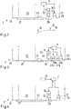
- a cover glass 21 of the microscope 2 is shown, which is arranged between a beam path 22 for generating the microscopic image and an outer area, for example the room with the patient 13 .
- the cover glass 21 can be transparent to radiation at least in the visible wavelength range, but protects the beam path 22 for generating the microscopic image from contamination.
- a visual field illumination device 23 which, like the beam path 22 , is integrated into a microscope body 24 of the microscope 2 . In this case, the cover glass 21 covers both the beam path 22 and the field of view illumination device 23 .
- a beam path 25 for generating the tracking image is also shown.
- This beam path 25 is also formed by the microscope body 24, but is different from the beam path 22 for generating the microscopic image, in particular separated by wall elements.
- a cover glass 26 is also shown, which is arranged between the beam path 25 and the external environment. The cover glass 26 can be transparent to light at least in the near infrared range and can be different from the cover glass 21 .
- a tracking illumination device 27 which is also integrated in the microscope body 24 of the microscope 2 and can be designed as an LED, for example. The tracking lighting device 27 is different from the visual field lighting device 23 . The tracking illuminator 27 can generate light in the near infrared range.
- a lens element 28 is arranged between the tracking lighting device 27 and the external environment.
- the lens element 28 can be a lens element whose shape and/or position can be changed, it being possible for a change in shape and/or position to be used to set different lighting states.
- the shape and/or position can be adjusted by the control device 7 .
- a tracking camera 30 (see 1 ), which includes an image sensor 34 for generating an image, in particular a two-dimensional image, a movable optical element 32 and a cover glass 26 .
- a control device 7 which is used to control the movable optical element 32, which is embodied, for example, as a lens.
- the control device 7 can be connected via a signal connection to a drive device for generating a drive force (not shown) that causes the movement.
- the optical element 32 can be moved with a translational movement in a beam path 25 to generate the tracking image, in particular parallel to a central axis of the beam path.
- the optical element 32 can be moved between two end stops, in particular with a linear movement.
- a detection area EB1, EB2 (see e.g 9 ) of the tracking camera 30 can be changed, in particular a detection angle EW1, EW2 of the detection area EB.
- the 2 The microscopy system 1 shown comprises precisely one or more tracking illumination device(s) 27. Operation of the tracking lighting device 27 can be controllable by the control device 7, in particular an activation state and/or an intensity of the radiation generated by the tracking lighting device 27 in the activated state.
- lighting information can be determined by evaluating at least one image of the tracking camera 30, eg a brightness value of the generated image or brightness values in one or more partial areas of the image.
- the control device 7 can be used to determine position information about the object, ie information about the position of a marker 31 relative to an illumination device, preferably relative to the visual field illumination device 23 .
- the illumination by the tracking illumination devices 27 and/or the image acquisition by the at least one tracking camera 30 can be adjusted by means of the control device 7 depending on the illumination information and/or the position information of the object.
- an illumination state and/or an image acquisition state can be set, with an illumination state being able to be set, for example, by setting at least one illumination parameter and/or an image acquisition state being set by setting at least one image acquisition parameter, e.g. the exposure time, and different states can differ in the value of at least one parameter.
- FIG. 3 shows a schematic cross section through part of a microscope system 2 according to the invention in a further embodiment.
- the microscopy system 2 shown has a plurality of tracking illumination devices 27a, 27b, 27c and a plurality of lens elements 28a, 28b, 28c.
- the lens elements 28a, 28b, 28c can have optical properties that differ from one another, in particular focal lengths that differ from one another.
- the radiation generated by the tracking lighting device 27a, 27b, 27c radiates through the lens element 28a, 28b, 28c assigned to this tracking lighting device 27a, 27b, 27c.
- the lens elements 28a, 28b, 28c can be formed by a compound lens element 29, this compound lens element 29 comprising different sections which form the lens elements 28a, 28b, 28c.
- the tracking lighting devices 27a, 27b, 27c can be controlled independently of one another by means of the control device 7 in order to adjust the lighting.
- the lens elements 28a, 28b, 28c can also be controlled independently of one another to adjust the lighting if, for example, their shape and/or position can be changed.
- the microscopy system 1 can comprise groups of a plurality of tracking illumination devices 27, in which case the tracking illumination devices 27 can be in the form of LEDs or can include one.
- a group includes one or more so-called LED array(s), each of the tracking lighting devices 27 of each group being able to be controlled individually.
- Different lens elements 28a, 28b, 28c can be assigned to different groups.
- FIG. 4 shows a schematic cross section through part of a microscope system 2 according to the invention in a further embodiment.
- the microscopy system 2 shown has a device 33 for determining a working distance D (see 9 ). This is connected to the control device 7 for information transmission. The lighting and/or the image acquisition can then also be adjusted as a function of the working distance D by means of the control device 7 .
- the position of the movable optical element 32 can also be adjusted as a function of the working distance D.
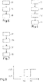
- FIG 5 shows a schematic flow diagram of a method according to the invention in a first embodiment.
- a tracking camera see e.g 2 creates an image.
- this image is then in particular with an evaluation device, e.g 2 illustrated control device 7, evaluated and - as explained above - a lighting information and / or position information of the object is determined.
- illumination by the tracking illumination device 27 and/or the image capture by the at least one tracking camera 30 is set, for example also by means of the control device 7, depending on the illumination information and/or the position information of the object.
- the illumination can take place by controlling the tracking illumination device(s) 27 and/or the lens element(s) 28 . Exemplary settings for the lighting and/or the image acquisition as a function of the lighting information and/or the position information of the object have been explained above.
- the method includes a step S11 for determining a working distance D.
- the illumination by the tracking illumination device 27 and/or the image capture by the at least one tracking camera 30 can also be adjusted as a function of the working distance D.
- the position of at least one optical element 32 can be set depending on the working distance.
- the method includes a step S12 for identifying partial areas in which markers 31 are imaged (see 2 ).
- this sub-area of the image is then evaluated and—as explained above—an item of lighting information is determined for these sub-areas.
- illumination by tracking illumination device 27 and/or image capture by the at least one tracking camera 30 is adjusted, for example also by means of control device 7, depending on the illumination information, in particular in such a way that markers 31, after adjustment, have a predetermined brightness are mapped.
- FIG. 8 shows a schematic representation of the relationship between a working distance D and illumination states S1, S2 and detection states, in a first detection state a first position L1 of an optical element 32 for setting a detection range EB of the tracking camera 30 and in a second Detection state a second position L2 of the optical element 32 is set. It is shown that the optical element 32 is moved from the first to the second position L1, L2 and a second illumination state S1 is set when the working distance D increases and reaches or exceeds a first predetermined threshold value th1.
- the movable optical element 32 is moved from this second position L2 to the first position L1 and/or a first illumination state S1 and/or a first image acquisition state is set from this second illumination state S2 or image acquisition state if the working distance D decreases and a second reaches or falls below a predetermined threshold value th2, which is smaller than the first threshold value th1.
- FIG. 9 a schematic view of different detection areas EB1, EB2, which are set for different working distances D1, D2. Also shown is the tracking camera 30, which can include a movable optical element 32, the position of which can be changed in order to set a detection range EB of the tracking camera 30.
- the tracking camera 30 can include a movable optical element 32, the position of which can be changed in order to set a detection range EB of the tracking camera 30.
- other options for setting different detection areas EB1, EB2 are also conceivable.
- a first working distance D1 between a first focal plane SE1 in which, for example, a first target area (area of interest) with a first surgical field SF can be arranged, and a closing element of an objective system of the microscope along an optical axis of the microscope, for example a first detection area EB1 set.
- This setting enables reliable detection of an instrument 19 with markers 31 located in the vicinity of the first surgical field SF1.
- a further focal plane SE2 in which, for example, a further target area with a further surgical field SF2 is arranged can be, and the closing element is set, for example, a second detection area EB2 with a smaller detection angle than the detection angle of the first detection area EB1.
- a hatched box indicates a range of working distances D for which the first or the further detection range EB1, EB2 can be set, with the setting of the first or further detection range EB1, EB2 when the working distance D changes to a value from this range depends on the initial value of the working distance D before the change.
Landscapes
- Physics & Mathematics (AREA)
- General Physics & Mathematics (AREA)
- Optics & Photonics (AREA)
- Engineering & Computer Science (AREA)
- Multimedia (AREA)
- Chemical & Material Sciences (AREA)
- Analytical Chemistry (AREA)
- Computer Vision & Pattern Recognition (AREA)
- Health & Medical Sciences (AREA)
- General Health & Medical Sciences (AREA)
- Surgery (AREA)
- Microscoopes, Condenser (AREA)
Priority Applications (4)
| Application Number | Priority Date | Filing Date | Title |
|---|---|---|---|
| EP22728150.8A EP4334770B1 (fr) | 2021-05-07 | 2022-05-06 | Système de microscopie et procédé de fonctionnement d'un système de microscopie |
| DE112022002477.1T DE112022002477A5 (de) | 2021-05-07 | 2022-05-06 | Mikroskopiesystem und Verfahren zum Betreiben eines Mikroskopiesystems |
| PCT/EP2022/062306 WO2022234099A1 (fr) | 2021-05-07 | 2022-05-06 | Système de microscopie et procédé de fonctionnement d'un système de microscopie |
| US18/387,836 US20240151957A1 (en) | 2021-05-07 | 2023-11-07 | Microscopy system and method for operating a microscopy system |
Applications Claiming Priority (2)
| Application Number | Priority Date | Filing Date | Title |
|---|---|---|---|
| EP21172759.9A EP4086684B1 (fr) | 2021-05-07 | 2021-05-07 | Système optique et procédé de fonctionnement d'un système optique |
| EP21172758.1A EP4086685A1 (fr) | 2021-05-07 | 2021-05-07 | Système de microscopie et procédé de fonctionnement d'un système de microscopie |
Publications (1)
| Publication Number | Publication Date |
|---|---|
| EP4086686A1 true EP4086686A1 (fr) | 2022-11-09 |
Family
ID=83509006
Family Applications (1)
| Application Number | Title | Priority Date | Filing Date |
|---|---|---|---|
| EP21216369.5A Withdrawn EP4086686A1 (fr) | 2021-05-07 | 2021-12-21 | Système de microscopie et procédé de fonctionnement d'un système de microscopie |
Country Status (1)
| Country | Link |
|---|---|
| EP (1) | EP4086686A1 (fr) |
Citations (5)
| Publication number | Priority date | Publication date | Assignee | Title |
|---|---|---|---|---|
| US20090002812A1 (en) * | 2007-06-28 | 2009-01-01 | Manfred Kuster | Microscope with centered illumination |
| US20120123205A1 (en) * | 2010-11-12 | 2012-05-17 | Emory University | Additional systems and methods for providing real-time anatomical guidance in a disgnostic or therapeutic procedure |
| US20160373626A1 (en) * | 2015-06-18 | 2016-12-22 | Google Inc. | Non-Canting VCM-Actuated Autofocus |
| US9827054B2 (en) | 2014-03-14 | 2017-11-28 | Synaptive Medical (Barbados) Inc. | Intelligent positioning system and methods therefore |
| DE102018206406B3 (de) | 2018-04-25 | 2019-09-12 | Carl Zeiss Meditec Ag | Mikroskopiesystem und Verfahren zum Betrieb eines Mikroskopiesystems |
-
2021
- 2021-12-21 EP EP21216369.5A patent/EP4086686A1/fr not_active Withdrawn
Patent Citations (5)
| Publication number | Priority date | Publication date | Assignee | Title |
|---|---|---|---|---|
| US20090002812A1 (en) * | 2007-06-28 | 2009-01-01 | Manfred Kuster | Microscope with centered illumination |
| US20120123205A1 (en) * | 2010-11-12 | 2012-05-17 | Emory University | Additional systems and methods for providing real-time anatomical guidance in a disgnostic or therapeutic procedure |
| US9827054B2 (en) | 2014-03-14 | 2017-11-28 | Synaptive Medical (Barbados) Inc. | Intelligent positioning system and methods therefore |
| US20160373626A1 (en) * | 2015-06-18 | 2016-12-22 | Google Inc. | Non-Canting VCM-Actuated Autofocus |
| DE102018206406B3 (de) | 2018-04-25 | 2019-09-12 | Carl Zeiss Meditec Ag | Mikroskopiesystem und Verfahren zum Betrieb eines Mikroskopiesystems |
Similar Documents
| Publication | Publication Date | Title |
|---|---|---|
| DE102018206406C5 (de) | Mikroskopiesystem | |
| EP4334770B1 (fr) | Système de microscopie et procédé de fonctionnement d'un système de microscopie | |
| DE4134481C2 (de) | Operationsmikroskop zur rechnergestützten, stereotaktischen Mikrochirurgie | |
| EP2870500B1 (fr) | Procédé de préparation et de la réalisation de l'enregistrement d'un empilage de vues d'un échantillon suivant des angles d'orientation différents | |
| EP2847540B1 (fr) | Module d'éclairage amélioré pour un appareil de mesure de coordonnées | |
| DE102021124535A1 (de) | System und verfahren mit mehrpunkt-autofokus zur ausrichtung einer optischen achse eines optischen abschnitts senkrecht zu einer werkstückoberfläche | |
| DE102013018547B4 (de) | Einrichtung zur Ausrichtung eines Fokussierobjektivs | |
| DE102017107178B4 (de) | Mikroskop mit Vorrichtung zum Erzeugen von reflexkorrigierten Abbildungen sowie Reflexkorrekturverfahren zum Korrigieren von digitalen mikroskopischen Abbildungen | |
| EP2976669A1 (fr) | Procédé et dispositif optique pour manipuler et reproduire un échantillon microscopique | |
| EP3159727B1 (fr) | Microscope (d'opération) electronique | |
| EP4334769B1 (fr) | Système de microscopie et procédé de fonctionnement d'un système de microscopie | |
| DE102016103736A1 (de) | Verfahren zur Bestimmung einer Höhenlage eines Objekts | |
| EP4086686A1 (fr) | Système de microscopie et procédé de fonctionnement d'un système de microscopie | |
| DE102006022592B4 (de) | Mikroskop mit Beleuchtungseinheit | |
| DE102018206405B3 (de) | Mikroskopiesystem sowie Verfahren zum Betrieb eines Mikroskopiesystems | |
| EP3303990A1 (fr) | Commande d'éclairage lors de l'utilisation d'appareils de mesure optiques | |
| DE4340461A1 (de) | Stereoskopische Bildaufnahmevorrichtung | |
| DE102022202555B4 (de) | Verfahren zum Bestimmen der dreidimensionalen Positionen von Punkten einer Zielregion an einem Patienten in einem Referenzkoordinatensystem eines chirurgischen Visualisierungssystems und chirurgisches Visualisierungssystem | |
| DE102013215445A1 (de) | Positionierung einer Aufnahmeeinrichtung zur Durchführung medizinischer Aufnahmen | |
| DE102018110644B4 (de) | Digitales Mikroskop und digitales Mikroskopieverfahren | |
| EP4086684B1 (fr) | Système optique et procédé de fonctionnement d'un système optique | |
| DE102024124224B3 (de) | Brennweitenparameterwert für kameramodell | |
| WO2026093300A1 (fr) | Système médical et procédé de réglage d'un foyer | |
| EP4208750B1 (fr) | Procédé de fonctionnement d'un système de microscopie et système de microscopie | |
| DE10362244B4 (de) | Verfahren zur Bestimmung der Fokusposition und der Verkippung der Fokusebene bei der Abbildung einer Probe |
Legal Events
| Date | Code | Title | Description |
|---|---|---|---|
| PUAI | Public reference made under article 153(3) epc to a published international application that has entered the european phase |
Free format text: ORIGINAL CODE: 0009012 |
|
| STAA | Information on the status of an ep patent application or granted ep patent |
Free format text: STATUS: THE APPLICATION HAS BEEN PUBLISHED |
|
| AK | Designated contracting states |
Kind code of ref document: A1 Designated state(s): AL AT BE BG CH CY CZ DE DK EE ES FI FR GB GR HR HU IE IS IT LI LT LU LV MC MK MT NL NO PL PT RO RS SE SI SK SM TR |
|
| STAA | Information on the status of an ep patent application or granted ep patent |
Free format text: STATUS: THE APPLICATION IS DEEMED TO BE WITHDRAWN |
|
| 18D | Application deemed to be withdrawn |
Effective date: 20230510 |