EP4089304B1 - Cartouche de vanne - Google Patents
Cartouche de vanne Download PDFInfo
- Publication number
- EP4089304B1 EP4089304B1 EP21173531.1A EP21173531A EP4089304B1 EP 4089304 B1 EP4089304 B1 EP 4089304B1 EP 21173531 A EP21173531 A EP 21173531A EP 4089304 B1 EP4089304 B1 EP 4089304B1
- Authority
- EP
- European Patent Office
- Prior art keywords
- valve
- spindle
- head piece
- valve cartridge
- fitting
- Prior art date
- Legal status (The legal status is an assumption and is not a legal conclusion. Google has not performed a legal analysis and makes no representation as to the accuracy of the status listed.)
- Active
Links
Images


Classifications
-
- F—MECHANICAL ENGINEERING; LIGHTING; HEATING; WEAPONS; BLASTING
- F16—ENGINEERING ELEMENTS AND UNITS; GENERAL MEASURES FOR PRODUCING AND MAINTAINING EFFECTIVE FUNCTIONING OF MACHINES OR INSTALLATIONS; THERMAL INSULATION IN GENERAL
- F16K—VALVES; TAPS; COCKS; ACTUATING-FLOATS; DEVICES FOR VENTING OR AERATING
- F16K3/00—Gate valves or sliding valves, i.e. cut-off apparatus with closing members having a sliding movement along the seat for opening and closing
- F16K3/02—Gate valves or sliding valves, i.e. cut-off apparatus with closing members having a sliding movement along the seat for opening and closing with flat sealing faces; Packings therefor
- F16K3/04—Gate valves or sliding valves, i.e. cut-off apparatus with closing members having a sliding movement along the seat for opening and closing with flat sealing faces; Packings therefor with pivoted closure members
- F16K3/06—Gate valves or sliding valves, i.e. cut-off apparatus with closing members having a sliding movement along the seat for opening and closing with flat sealing faces; Packings therefor with pivoted closure members in the form of closure plates arranged between supply and discharge passages
- F16K3/08—Gate valves or sliding valves, i.e. cut-off apparatus with closing members having a sliding movement along the seat for opening and closing with flat sealing faces; Packings therefor with pivoted closure members in the form of closure plates arranged between supply and discharge passages with circular plates rotatable around their centres
- F16K3/085—Gate valves or sliding valves, i.e. cut-off apparatus with closing members having a sliding movement along the seat for opening and closing with flat sealing faces; Packings therefor with pivoted closure members in the form of closure plates arranged between supply and discharge passages with circular plates rotatable around their centres the axis of supply passage and the axis of discharge passage being coaxial and parallel to the axis of rotation of the plates
-
- F—MECHANICAL ENGINEERING; LIGHTING; HEATING; WEAPONS; BLASTING
- F16—ENGINEERING ELEMENTS AND UNITS; GENERAL MEASURES FOR PRODUCING AND MAINTAINING EFFECTIVE FUNCTIONING OF MACHINES OR INSTALLATIONS; THERMAL INSULATION IN GENERAL
- F16K—VALVES; TAPS; COCKS; ACTUATING-FLOATS; DEVICES FOR VENTING OR AERATING
- F16K25/00—Details relating to contact between valve members and seats
-
- F—MECHANICAL ENGINEERING; LIGHTING; HEATING; WEAPONS; BLASTING
- F16—ENGINEERING ELEMENTS AND UNITS; GENERAL MEASURES FOR PRODUCING AND MAINTAINING EFFECTIVE FUNCTIONING OF MACHINES OR INSTALLATIONS; THERMAL INSULATION IN GENERAL
- F16K—VALVES; TAPS; COCKS; ACTUATING-FLOATS; DEVICES FOR VENTING OR AERATING
- F16K27/00—Construction of housing; Use of materials therefor
- F16K27/04—Construction of housing; Use of materials therefor of sliding valves
- F16K27/044—Construction of housing; Use of materials therefor of sliding valves slide valves with flat obturating members
- F16K27/045—Construction of housing; Use of materials therefor of sliding valves slide valves with flat obturating members with pivotal obturating members
-
- F—MECHANICAL ENGINEERING; LIGHTING; HEATING; WEAPONS; BLASTING
- F16—ENGINEERING ELEMENTS AND UNITS; GENERAL MEASURES FOR PRODUCING AND MAINTAINING EFFECTIVE FUNCTIONING OF MACHINES OR INSTALLATIONS; THERMAL INSULATION IN GENERAL
- F16K—VALVES; TAPS; COCKS; ACTUATING-FLOATS; DEVICES FOR VENTING OR AERATING
- F16K31/00—Actuating devices; Operating means; Releasing devices
- F16K31/02—Actuating devices; Operating means; Releasing devices electric; magnetic
- F16K31/04—Actuating devices; Operating means; Releasing devices electric; magnetic using a motor
- F16K31/041—Actuating devices; Operating means; Releasing devices electric; magnetic using a motor for rotating valves
-
- F—MECHANICAL ENGINEERING; LIGHTING; HEATING; WEAPONS; BLASTING
- F16—ENGINEERING ELEMENTS AND UNITS; GENERAL MEASURES FOR PRODUCING AND MAINTAINING EFFECTIVE FUNCTIONING OF MACHINES OR INSTALLATIONS; THERMAL INSULATION IN GENERAL
- F16K—VALVES; TAPS; COCKS; ACTUATING-FLOATS; DEVICES FOR VENTING OR AERATING
- F16K31/00—Actuating devices; Operating means; Releasing devices
- F16K31/44—Mechanical actuating means
- F16K31/53—Mechanical actuating means with toothed gearing
- F16K31/535—Mechanical actuating means with toothed gearing for rotating valves
-
- F—MECHANICAL ENGINEERING; LIGHTING; HEATING; WEAPONS; BLASTING
- F16—ENGINEERING ELEMENTS AND UNITS; GENERAL MEASURES FOR PRODUCING AND MAINTAINING EFFECTIVE FUNCTIONING OF MACHINES OR INSTALLATIONS; THERMAL INSULATION IN GENERAL
- F16K—VALVES; TAPS; COCKS; ACTUATING-FLOATS; DEVICES FOR VENTING OR AERATING
- F16K2200/00—Details of valves
- F16K2200/50—Self-contained valve assemblies
- F16K2200/501—Cartridge valves
Definitions
- the invention relates to a valve cartridge, with a head piece, which is penetrated in the middle by a spindle, which is rotatably and axially displaceably held in the head piece and which has an axial through-hole for the passage of water, a valve being actuable through the spindle the flow through the through hole can be controlled.
- valve top parts The exit of media from fittings is controlled with the help of valve top parts.
- the valve upper part is screwed into the housing of a fitting using its head piece.
- the spindle is connected to a lever through which it can be rotated.
- known valve top parts cf. DE 32 07 895 C2 , DE 36 38 180 C2 , DE 87 15 044 111
- two discs are provided to control the flow.
- the discs are made of ceramic material.
- One of the two disks - control disk - is rotatably arranged in the upper part of the valve with the help of a driver connected to the spindle.
- the other disc - inlet disc - is a fixed valve seat disc, also called a fixed disc.
- the flow of water can be controlled with straight-through valve fittings.
- a straight-through valve is described, with a housing that has a water inlet connection and a water outlet connection.
- a valve tappet is arranged perpendicular to the water passage area and can be moved into the water passage area via an actuating device, whereby the water flow can be controlled.
- Another through valve is in the DE 83 07 769 U1 described.
- the valve body is formed by a rotatable disc-shaped control element, which is arranged in the water passage area and is arranged to be rotatable relative to two fixed discs.
- the invention aims to provide a remedy here.
- the invention is based on the object of providing a valve cartridge which enables a through-valve fitting to be designed with minimal installation space. According to the invention, this object is achieved by a valve cartridge with the features of patent claim 1.
- the invention provides a valve cartridge which enables a through-valve fitting to be designed with minimal installation space. Because the spindle has an axial bore for water to pass through and is held rotatably and axially displaceably in the head piece, a very compact design of the valve cartridge can be achieved, since the head piece in particular does not have multiple shoulders for axially fixing the spindle, which means that the outer diameter of the head piece is minimized. At the same time, the diameter of the hole for water flow can be maximized.
- the axial fixation of the spindle can take place during integration into the straight-through valve fitting using a stop provided here.
- the spindle has a coupling section outside the head piece with a non-round, preferably polygonal cross-section. This enables a space-minimized coupling with a control panel within a straight-way valve fitting.
- the head piece has an integrated valve seat on which the valve comes into contact.
- the valve is preferably formed by a control disk and an inlet disk which lies against it and is held in the head piece in a rotationally fixed manner.
- a seal is advantageously arranged between the inlet disk and the valve seat, which is preferably designed as a lip seal.
- the head piece has a section on the inside with an inner diameter that narrows conically in the direction of the spindle and through which the valve seat is formed. This is targeted leadership of the water flow on the passage area of the passage disk, while at the same time a very compact integration of a valve seat is achieved.
- the spindle has at least one driving pin at the end, via which it is positively connected to the control disk. This creates a compact, rotation-proof connection between the spindle and the control disk.
- the head piece has at least one positioning lug at its end facing the spindle. This enables a simple, correct installation of the valve cartridge by engaging the at least one positioning lug in a positioning recess arranged in a fitting. Alternatively or additionally, at least one positioning lug can also be arranged on the end of the head piece facing away from the spindle.
- the invention is also based on the object of providing a through-valve fitting that minimizes installation space. According to the invention, this object is achieved by a fitting with the features of patent claim 9.
- a cartridge of the above type is inserted into the fitting, with the spindle resting with its free end on a stop arranged in the fitting, whereby it is axially fixed, enables a very compact design of the fitting housing.
- the spindle can rest against the stop directly or indirectly, for example via a sealing or sliding disk.
- An actuating part is preferably arranged which is positively connected to the coupling section.
- the actuating part can be formed by a pivotable lever or a motor drive.
- the motor drive is formed by an electric motor which is connected to the coupling section via a bevel gear.
- a bevel gear This allows for a compact connection of the electric motor to the Spindle allows.
- the motor can be arranged perpendicular to the spindle.
- the bevel gear of the bevel gear is advantageously annular and has an inner contour that corresponds to the outer contour of the coupling section onto which it is pushed.
- the bevel gear is formed by a ring part on which a bevel gear segment is formed, that is to say is arranged in one piece. This results in a compact design.
- the conical projection of the bevel gear is only guided around the ring part as far as is necessary for the maximum rotation of the spindle.
- the conical projection of the bevel gear segment spans an angle of between 100° and 130° of the ring part.
- a water inlet connection and a water outlet connection are arranged, which are aligned with one another and between which the valve cartridge is arranged. This results in a compact design of the fitting.
- the valve cartridge chosen as an exemplary embodiment has a head piece 1, which is penetrated in the middle by a spindle 2 guided radially in it.
- a valve can be actuated via spindle 2 and comes into contact with a valve seat 16 arranged in the head piece 1.
- the valve is formed by a control disk 3 and an inlet disk 4.
- the control disk 3 is positively connected to the spindle 2 and guided radially in the head piece 1.
- the inlet disk 4 is arranged in the head piece 1, which is followed by a lip seal 5 which comes into contact with the valve seat 16 of the head piece 1.
- the control disk 3 lies sealingly on the inlet disk 4.
- the control disk 3 and the inlet disk 4 are designed as ceramic disks.
- the head piece 1 is designed as a brass turned part and consists of a cylindrical hollow body, in the outer surface of which a groove 11 for receiving an O-ring 9 is made. On its end face opposite the groove 11 there are two positioning lugs diametrically opposite each other 13 arranged. At the level of the groove 11, a diameter-reduced section 14 is arranged on the inside with an inner diameter that narrows conically in the direction of the positioning lugs and merges into a cylindrical passage 15. The reduced-diameter section 14 has an annular surface that forms the valve seat 16. A groove 17 for receiving the lip seal 5 is made in the inner surface of the head piece at a distance from the valve seat 16.
- the head piece 1 On its side facing the positioning lugs 13, the head piece 1 also has an annular groove 18 on the inside, through which a shoulder 19 is formed to support the collar 23 of the spindle 2 in the course of integration into a straight-through valve fitting.
- two axial grooves 12 are arranged diametrically opposite each other on the inside and extend from the shoulder 19 to the groove 17. The axial grooves 12 accommodate the lugs 41 of the inlet disk 4, whereby it is held in the head piece 1 in a rotationally fixed manner.
- the spindle 2 is designed as a substantially cylindrical brass turned part and has an axial through hole 21 centrally for the passage of water.
- two driving pins 22 are arranged diametrically opposite each other for a positive connection to the control disk 3.
- the driving pins 22 are adjoined by a circumferential collar 23, into which a sealing groove 24 for receiving an O-ring 91 is introduced.
- the spindle 21 is sealed from the head piece 1 via the O-ring 91.
- a coupling section 25 is formed on the outer surface of the spindle 2, which is designed in the form of an irregular hexagon.
- a circumferential annular web 26 is arranged, which accommodates a sliding disk 92.
- a sealing groove 27 for receiving a further O-ring 93 is introduced into the spindle at a distance from the ring web 26.
- the spindle 2 is rotatable but axially displaceable in the head piece 1.
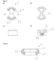
- the control disk 3 has a substantially barrel-shaped design, from which two opposing circular sections 31 are excluded. In the exemplary embodiment, the circular sections 31 have an angle of approximately 90°.
- the control disk 3 On its side facing the spindle 2, the control disk 3 has an annular extension 32.
- the annular extension 32 includes in assembled State the driving pins 22 of the spindle 2. At the foot of the extension 32, recesses 33 are formed, each of which holds a driving pin 22.
- a recess 34 is made in the control disk 3 on its end face facing away from the spindle 2.
- the inlet disk 4 is essentially cylindrical and has two noses 41 arranged diametrically opposite one another on its circumference. With the lugs 41, the inlet disk 4 fits into the axial grooves 12, which are arranged on the inside of the head piece 1, whereby the inlet disk 4 is held in the head piece 1 in a rotationally fixed manner.
- the inlet disk 4 rests on the lip 52 of the lip seal 5 and has sector-shaped passage openings 42. In the exemplary embodiment, two diametrically opposed passage openings 42 are arranged.
- the lip seal 5 is made of rubber and comprises a ring piece 51, on which a lip 52 is formed on its end face facing the inlet disk 4.
- the lip 52 has a substantially trapezoidal shape in cross section.
- the lip 52 is arranged at an angle to the horizontal.
- the outer surface of the lip 52 lies against the inlet disk 4 in a sealing manner.
- the ring piece 51 is provided on the outside with a collar 53 which engages in the groove of the 17 of the head piece 1.
- a bead 54 is formed on the inside of the center piece 51. The outside of the bead 54 lies flat on the valve seat 16 of the reduced-diameter section 14.
- FIG. 7 a fitting housing 6 is shown, with a water flow channel into which a valve cartridge according to the invention is inserted.
- the fitting housing 6 includes a water inlet section 61 and a water outlet section 62, through which the water flow channel is guided, as well as a drive section 63.
- the water inlet section 61 has a cylindrical cartridge receptacle 611, which is delimited by a section 612 with reduced inner diameter, through which a stop 613 is formed. In the stop 613 are diametrical two positioning recesses 614 are introduced opposite each other. At the end, the water inlet section 61 has an external thread 615 for connecting a water inlet line.
- the water outlet section 62 comprises a stepped bore 621, which has a first cylindrical section 622, which is followed by a second cylindrical, reduced inner diameter section 623, which merges into a conically tapered section 624, which opens into a third cylindrical section 625, to which a fourth cylindrical, diameter-enlarged section 626 connects, through which an annular contact surface 627 is formed.
- the water drain section 62 has an external thread 628 for connecting a water drain line.
- the drive section 63 is essentially cylindrical and opens into a gear room 64, which has a passage 641 which opens between the water inlet section 61 and the water outlet section 62. Furthermore, a measuring bore 631 is arranged in the drive section 63, which opens into the second section 623 of the stepped bore 621.
- the valve cartridge is inserted into the cartridge holder 611, with the head piece 1 resting against the stop 613.
- the two positioning lugs 13 of the head piece 1 engage in the positioning recesses 614, which ensures correct installation.
- the head piece is sealed against the cartridge holder 611 via the O-ring 9.
- the spindle 2 of the valve cartridge protrudes through the section 612 with a reduced inner diameter.
- a bevel gear 71 of a bevel gear 7 is applied to the coupling section 25, which in the exemplary embodiment is formed from a hollow cylindrical ring part 711, on which a bevel gear segment 712 is arranged on the outside.
- the bevel gear segment 712 spans an angle of 110° of the ring part 711. Depending on the maximum desired angle of rotation of the spindle 2, the bevel gear segment 712 can also span a smaller or a larger angle of the ring part 711.
- the ring part 711 has an irregular inner contour Hexagon, which corresponds to the outer contour of the coupling section 25 on which it is arranged.
- the bevel gear 71 is positively connected to the spindle, with the bevel gear 71 protruding into the passage 641 with its bevel gear segment 712.
- the spindle 2 rests on the contact surface 627 of the water drain section 62 via the sliding disk 92. Radially, the spindle 2 is sealed relative to the fourth cylindrical section 626 of the stepped bore 621 via the O-ring 93 arranged in the sealing groove 27.
- An electric motor 8 is arranged in the drive section 63, the drive shaft 81 of which projects into the transmission chamber 64.
- a bevel pinion 72 is mounted on the drive shaft 81 and engages with the bevel gear segment 712 of the bevel gear 71.
- a control and regulating device - not shown - is arranged, which is connected to a sensor inserted into the measuring bore 631, preferably a flow and / or temperature sensor, and via which the electric motor 8 can be controlled.
Landscapes
- Engineering & Computer Science (AREA)
- General Engineering & Computer Science (AREA)
- Mechanical Engineering (AREA)
- Sliding Valves (AREA)
- Multiple-Way Valves (AREA)
- Domestic Plumbing Installations (AREA)
Claims (15)
- Cartouche de vanne, comprenant une vanne et une pièce têtière (1) traversée en son centre par une broche (2) maintenue dans la pièce têtière (1) de façon à pouvoir tourner et à être décalable axialement, et qui présente un alésage axial traversant (21) pour le passage de l'eau, sachant que la vanne est actionnable par la broche (2) et qu'elle permet de commander le débit de l'eau qui passe par l'alésage traversant (21) et sachant que la broche (2) présente, hors de la pièce têtière (1), un segment de couplage (25) dont la section n'est pas ronde.
- Cartouche de vanne selon la revendication 1, caractérisée en ce que le segment de couplage (25) présente une section polygonale.
- Cartouche de vanne selon la revendication 1 ou 2, caractérisée en ce que la pièce têtière (1) présente un siège (16) de vanne intégré sur lequel la vanne vient appliquer.
- Cartouche de vanne selon la revendication 3, caractérisée en ce que la vanne est formée par un disque de commande (3) et par un disque d'admission (4) appliquant contre le disque premier cité et maintenu dans la pièce têtière (1) de façon à ne pas pouvoir tourner.
- Cartouche de vanne selon la revendication 4, caractérisée en ce qu'entre le disque d'admission (4) et le siège de vanne (16) est disposé un joint configuré de manière préférentielle en joint à lèvres (5).
- Cartouche de vanne selon l'une des revendications 3 à 5, caractérisée en ce que la pièce têtière (1) présente à l'intérieur un segment (14) dont le diamètre intérieur - par lequel est formé le siège (16) de vanne - va diminuant comme un cône en direction de la broche.
- Cartouche de vanne selon l'une des revendications 4 à 6, caractérisée en ce que la broche (2) présente à son extrémité au moins un taquet entraîneur (22) via lequel elle est reliée par adhérence de formes avec le disque de commande (3).
- Cartouche de vanne selon l'une des revendications précédentes, caractérisée en ce que la pièce têtière (1) présente, à son extrémité regardant la broche (2) et/ou à son extrémité ne regardant pas la broche (2), au moins une saillie de positionnement (13).
- Robinetterie, comprenant un conduit de passage de l'eau dans lequel est introduite une cartouche de vanne selon l'une des revendications précédentes, sachant que la broche (2) applique par son extrémité libre contre une butée (627) disposée dans le boîtier (6) de la robinetterie, ce qui a pour effet de l'immobiliser axialement.
- Robinetterie selon la revendication 9, caractérisée en ce qu'est disposée une pièce d'actionnement reliée par adhérence de formes avec le segment de couplage (25).
- Robinetterie selon la revendication 10, caractérisée en ce que la pièce d'actionnement comprend un levier pivotant ou un entraînement motorisé.
- Robinetterie selon la revendication 11, caractérisée en ce que l'entraînement motorisé est formé par un moteur électrique (8) relié, via une transmission (7) à engrenages coniques, au segment de couplage (25).
- Robinetterie selon la revendication 12, caractérisée en ce que l'engrenage conique (71) de la transmission (7) à engrenages coniques est configuré annulaire et présente un contour intérieur épousant le contour extérieur du segment de couplage (25) sur lequel il est enfilé.
- Robinetterie selon la revendication 13, caractérisée en ce que l'engrenage conique (71) est formé par une pièce annulaire (711) contre laquelle est moulé un segment (712) d'engrenage conique, segment qui présente un angle de préférence compris entre 100° et 130°.
- Robinetterie selon l'une des revendications 9 à 14, caractérisée en ce que sont disposés un raccord d'arrivée d'eau et un raccord d'évacuation d'eau réciproquement alignés, et que la cartouche de vanne est disposée entre eux.
Priority Applications (7)
| Application Number | Priority Date | Filing Date | Title |
|---|---|---|---|
| HUE21173531A HUE065770T2 (hu) | 2021-05-12 | 2021-05-12 | Szelep kartus |
| ES21173531T ES2974773T3 (es) | 2021-05-12 | 2021-05-12 | Cartucho de válvula |
| EP21173531.1A EP4089304B1 (fr) | 2021-05-12 | 2021-05-12 | Cartouche de vanne |
| TW110120060A TWI906306B (zh) | 2021-05-12 | 2021-06-02 | 閥芯 |
| PCT/EP2022/057171 WO2022238033A1 (fr) | 2021-05-12 | 2022-03-18 | Cartouche de soupape |
| US18/267,514 US12338907B2 (en) | 2021-05-12 | 2022-03-18 | Valve cartridge |
| CN202280034571.XA CN117377842A (zh) | 2021-05-12 | 2022-03-18 | 阀筒 |
Applications Claiming Priority (1)
| Application Number | Priority Date | Filing Date | Title |
|---|---|---|---|
| EP21173531.1A EP4089304B1 (fr) | 2021-05-12 | 2021-05-12 | Cartouche de vanne |
Publications (3)
| Publication Number | Publication Date |
|---|---|
| EP4089304A1 EP4089304A1 (fr) | 2022-11-16 |
| EP4089304B1 true EP4089304B1 (fr) | 2023-12-27 |
| EP4089304C0 EP4089304C0 (fr) | 2023-12-27 |
Family
ID=75914378
Family Applications (1)
| Application Number | Title | Priority Date | Filing Date |
|---|---|---|---|
| EP21173531.1A Active EP4089304B1 (fr) | 2021-05-12 | 2021-05-12 | Cartouche de vanne |
Country Status (7)
| Country | Link |
|---|---|
| US (1) | US12338907B2 (fr) |
| EP (1) | EP4089304B1 (fr) |
| CN (1) | CN117377842A (fr) |
| ES (1) | ES2974773T3 (fr) |
| HU (1) | HUE065770T2 (fr) |
| TW (1) | TWI906306B (fr) |
| WO (1) | WO2022238033A1 (fr) |
Families Citing this family (2)
| Publication number | Priority date | Publication date | Assignee | Title |
|---|---|---|---|---|
| ES2968026T3 (es) * | 2021-08-18 | 2024-05-06 | Fluehs Drehtechnik Gmbh | Cartucho de válvula |
| CN116255470B (zh) * | 2023-02-15 | 2025-07-25 | 上海瑞泰消防设备制造有限公司 | 一种基于转速调节流量的调节阀 |
Citations (1)
| Publication number | Priority date | Publication date | Assignee | Title |
|---|---|---|---|---|
| US20190001350A1 (en) * | 2017-06-28 | 2019-01-03 | Kylin Sanitary Technology (Xiamen) Co., Ltd. | Flow control component and shower |
Family Cites Families (11)
| Publication number | Priority date | Publication date | Assignee | Title |
|---|---|---|---|---|
| DE3207895C2 (de) | 1982-03-05 | 1983-12-29 | Fa. Otto Flühs, 5880 Lüdenscheid | Ventiloberteil für Sanitärarmaturen |
| DE8307769U1 (de) | 1983-03-17 | 1983-09-22 | Ideal-Standard Gmbh, 5300 Bonn | Durchgangsventil |
| DE3638180A1 (de) | 1986-11-08 | 1988-05-19 | Fluehs Drehtechnik Gmbh | Ventiloberteil |
| DE8715044U1 (de) | 1987-11-12 | 1988-01-14 | Flühs Drehtechnik GmbH, 5880 Lüdenscheid | Ventiloberteil für Sanitärarmaturen |
| US5025832A (en) * | 1990-09-14 | 1991-06-25 | Taylor Julian S | Multiple orifice rotatable disc in-line restrictor valve |
| JP3462452B2 (ja) | 2000-07-07 | 2003-11-05 | Smc株式会社 | 二方弁 |
| US8136789B2 (en) * | 2007-10-30 | 2012-03-20 | Molon Motor And Coil Corporation | Drain valve actuators and methods of controlling drain valves |
| CN203477390U (zh) * | 2013-09-04 | 2014-03-12 | 刘伟 | 一种直通型小流量调节阀 |
| CN206530723U (zh) * | 2017-02-15 | 2017-09-29 | 邓淇潞 | 陶瓷磨片阀芯开关装置 |
| DE202018100921U1 (de) * | 2018-02-20 | 2019-05-23 | Klaus Klee | Keramisches Scheibenventil |
| CN212338229U (zh) * | 2020-09-02 | 2021-01-12 | 烟台金泰美林科技股份有限公司 | 全衬陶瓷轮阀 |
-
2021
- 2021-05-12 ES ES21173531T patent/ES2974773T3/es active Active
- 2021-05-12 HU HUE21173531A patent/HUE065770T2/hu unknown
- 2021-05-12 EP EP21173531.1A patent/EP4089304B1/fr active Active
- 2021-06-02 TW TW110120060A patent/TWI906306B/zh active
-
2022
- 2022-03-18 WO PCT/EP2022/057171 patent/WO2022238033A1/fr not_active Ceased
- 2022-03-18 CN CN202280034571.XA patent/CN117377842A/zh active Pending
- 2022-03-18 US US18/267,514 patent/US12338907B2/en active Active
Patent Citations (1)
| Publication number | Priority date | Publication date | Assignee | Title |
|---|---|---|---|---|
| US20190001350A1 (en) * | 2017-06-28 | 2019-01-03 | Kylin Sanitary Technology (Xiamen) Co., Ltd. | Flow control component and shower |
Also Published As
| Publication number | Publication date |
|---|---|
| US12338907B2 (en) | 2025-06-24 |
| TW202244414A (zh) | 2022-11-16 |
| TWI906306B (zh) | 2025-12-01 |
| WO2022238033A1 (fr) | 2022-11-17 |
| CN117377842A (zh) | 2024-01-09 |
| EP4089304C0 (fr) | 2023-12-27 |
| EP4089304A1 (fr) | 2022-11-16 |
| US20240035576A1 (en) | 2024-02-01 |
| ES2974773T3 (es) | 2024-07-01 |
| HUE065770T2 (hu) | 2024-06-28 |
Similar Documents
| Publication | Publication Date | Title |
|---|---|---|
| EP3420430B1 (fr) | Vanne de mélange thermostatique | |
| EP4089304B1 (fr) | Cartouche de vanne | |
| EP3074676B1 (fr) | Robinetterie sanitaire | |
| DE3421653C2 (de) | Ventil | |
| EP1696158A1 (fr) | Tête de robinet | |
| CH646502A5 (de) | Drehschieberventilanordnung. | |
| EP0653581B1 (fr) | Robinet mitigeur et d'arrêt | |
| EP1462692B1 (fr) | Tête de robinet | |
| EP4137722B1 (fr) | Cartouche de vanne | |
| WO2013010845A1 (fr) | Partie supérieure de soupape pour robinetterie | |
| EP3265704B1 (fr) | Pièce supérieure de soupape pour robinetterie | |
| EP3112540B1 (fr) | Partie superieure de soupape | |
| EP3702651B1 (fr) | Partie supérieure de soupape pour robinetteries sanitaires | |
| EP1342996B1 (fr) | Connexion pour compteur d'eau | |
| EP3591271B1 (fr) | Partie supérieure de soupape | |
| DE3031380C2 (de) | Drehschieber | |
| DE102006027558B4 (de) | Ventiloberteil | |
| DE1500110C3 (de) | Einrichtung zur Voreinstellung für einen Heizkörperhahn | |
| EP3693643B1 (fr) | Partie supérieure de soupape pour robinetteries sanitaires | |
| DE20309724U1 (de) | Ventiloberteil für Armaturen | |
| DE20008679U1 (de) | Ventiloberteil für Armaturen | |
| DE202021104414U1 (de) | Ventilkartusche | |
| DE202024102491U1 (de) | Mischventilkartusche | |
| EP4650632A1 (fr) | Cartouche de robinet mitigeur | |
| EP2829779B1 (fr) | Partie supérieure de soupape |
Legal Events
| Date | Code | Title | Description |
|---|---|---|---|
| PUAI | Public reference made under article 153(3) epc to a published international application that has entered the european phase |
Free format text: ORIGINAL CODE: 0009012 |
|
| STAA | Information on the status of an ep patent application or granted ep patent |
Free format text: STATUS: EXAMINATION IS IN PROGRESS |
|
| 17P | Request for examination filed |
Effective date: 20220426 |
|
| AK | Designated contracting states |
Kind code of ref document: A1 Designated state(s): AL AT BE BG CH CY CZ DE DK EE ES FI FR GB GR HR HU IE IS IT LI LT LU LV MC MK MT NL NO PL PT RO RS SE SI SK SM TR |
|
| GRAP | Despatch of communication of intention to grant a patent |
Free format text: ORIGINAL CODE: EPIDOSNIGR1 |
|
| STAA | Information on the status of an ep patent application or granted ep patent |
Free format text: STATUS: GRANT OF PATENT IS INTENDED |
|
| INTG | Intention to grant announced |
Effective date: 20230802 |
|
| GRAS | Grant fee paid |
Free format text: ORIGINAL CODE: EPIDOSNIGR3 |
|
| GRAA | (expected) grant |
Free format text: ORIGINAL CODE: 0009210 |
|
| STAA | Information on the status of an ep patent application or granted ep patent |
Free format text: STATUS: THE PATENT HAS BEEN GRANTED |
|
| AK | Designated contracting states |
Kind code of ref document: B1 Designated state(s): AL AT BE BG CH CY CZ DE DK EE ES FI FR GB GR HR HU IE IS IT LI LT LU LV MC MK MT NL NO PL PT RO RS SE SI SK SM TR |
|
| REG | Reference to a national code |
Ref country code: GB Ref legal event code: FG4D Free format text: NOT ENGLISH |
|
| REG | Reference to a national code |
Ref country code: CH Ref legal event code: EP |
|
| REG | Reference to a national code |
Ref country code: DE Ref legal event code: R096 Ref document number: 502021002258 Country of ref document: DE |
|
| REG | Reference to a national code |
Ref country code: IE Ref legal event code: FG4D Free format text: LANGUAGE OF EP DOCUMENT: GERMAN |
|
| U01 | Request for unitary effect filed |
Effective date: 20240123 |
|
| U07 | Unitary effect registered |
Designated state(s): AT BE BG DE DK EE FI FR IT LT LU LV MT NL PT SE SI Effective date: 20240131 |
|
| PG25 | Lapsed in a contracting state [announced via postgrant information from national office to epo] |
Ref country code: GR Free format text: LAPSE BECAUSE OF FAILURE TO SUBMIT A TRANSLATION OF THE DESCRIPTION OR TO PAY THE FEE WITHIN THE PRESCRIBED TIME-LIMIT Effective date: 20240328 |
|
| PG25 | Lapsed in a contracting state [announced via postgrant information from national office to epo] |
Ref country code: GR Free format text: LAPSE BECAUSE OF FAILURE TO SUBMIT A TRANSLATION OF THE DESCRIPTION OR TO PAY THE FEE WITHIN THE PRESCRIBED TIME-LIMIT Effective date: 20240328 |
|
| PG25 | Lapsed in a contracting state [announced via postgrant information from national office to epo] |
Ref country code: RS Free format text: LAPSE BECAUSE OF FAILURE TO SUBMIT A TRANSLATION OF THE DESCRIPTION OR TO PAY THE FEE WITHIN THE PRESCRIBED TIME-LIMIT Effective date: 20231227 Ref country code: NO Free format text: LAPSE BECAUSE OF FAILURE TO SUBMIT A TRANSLATION OF THE DESCRIPTION OR TO PAY THE FEE WITHIN THE PRESCRIBED TIME-LIMIT Effective date: 20240327 Ref country code: HR Free format text: LAPSE BECAUSE OF FAILURE TO SUBMIT A TRANSLATION OF THE DESCRIPTION OR TO PAY THE FEE WITHIN THE PRESCRIBED TIME-LIMIT Effective date: 20231227 |
|
| U20 | Renewal fee for the european patent with unitary effect paid |
Year of fee payment: 4 Effective date: 20240523 |
|
| REG | Reference to a national code |
Ref country code: HU Ref legal event code: AG4A Ref document number: E065770 Country of ref document: HU |
|
| PG25 | Lapsed in a contracting state [announced via postgrant information from national office to epo] |
Ref country code: IS Free format text: LAPSE BECAUSE OF FAILURE TO SUBMIT A TRANSLATION OF THE DESCRIPTION OR TO PAY THE FEE WITHIN THE PRESCRIBED TIME-LIMIT Effective date: 20240427 |
|
| REG | Reference to a national code |
Ref country code: ES Ref legal event code: FG2A Ref document number: 2974773 Country of ref document: ES Kind code of ref document: T3 Effective date: 20240701 |
|
| PG25 | Lapsed in a contracting state [announced via postgrant information from national office to epo] |
Ref country code: CZ Free format text: LAPSE BECAUSE OF FAILURE TO SUBMIT A TRANSLATION OF THE DESCRIPTION OR TO PAY THE FEE WITHIN THE PRESCRIBED TIME-LIMIT Effective date: 20231227 |
|
| PG25 | Lapsed in a contracting state [announced via postgrant information from national office to epo] |
Ref country code: SK Free format text: LAPSE BECAUSE OF FAILURE TO SUBMIT A TRANSLATION OF THE DESCRIPTION OR TO PAY THE FEE WITHIN THE PRESCRIBED TIME-LIMIT Effective date: 20231227 |
|
| PG25 | Lapsed in a contracting state [announced via postgrant information from national office to epo] |
Ref country code: SM Free format text: LAPSE BECAUSE OF FAILURE TO SUBMIT A TRANSLATION OF THE DESCRIPTION OR TO PAY THE FEE WITHIN THE PRESCRIBED TIME-LIMIT Effective date: 20231227 Ref country code: SK Free format text: LAPSE BECAUSE OF FAILURE TO SUBMIT A TRANSLATION OF THE DESCRIPTION OR TO PAY THE FEE WITHIN THE PRESCRIBED TIME-LIMIT Effective date: 20231227 Ref country code: RO Free format text: LAPSE BECAUSE OF FAILURE TO SUBMIT A TRANSLATION OF THE DESCRIPTION OR TO PAY THE FEE WITHIN THE PRESCRIBED TIME-LIMIT Effective date: 20231227 Ref country code: IS Free format text: LAPSE BECAUSE OF FAILURE TO SUBMIT A TRANSLATION OF THE DESCRIPTION OR TO PAY THE FEE WITHIN THE PRESCRIBED TIME-LIMIT Effective date: 20240427 Ref country code: CZ Free format text: LAPSE BECAUSE OF FAILURE TO SUBMIT A TRANSLATION OF THE DESCRIPTION OR TO PAY THE FEE WITHIN THE PRESCRIBED TIME-LIMIT Effective date: 20231227 |
|
| PG25 | Lapsed in a contracting state [announced via postgrant information from national office to epo] |
Ref country code: PL Free format text: LAPSE BECAUSE OF FAILURE TO SUBMIT A TRANSLATION OF THE DESCRIPTION OR TO PAY THE FEE WITHIN THE PRESCRIBED TIME-LIMIT Effective date: 20231227 |
|
| PG25 | Lapsed in a contracting state [announced via postgrant information from national office to epo] |
Ref country code: PL Free format text: LAPSE BECAUSE OF FAILURE TO SUBMIT A TRANSLATION OF THE DESCRIPTION OR TO PAY THE FEE WITHIN THE PRESCRIBED TIME-LIMIT Effective date: 20231227 |
|
| REG | Reference to a national code |
Ref country code: DE Ref legal event code: R097 Ref document number: 502021002258 Country of ref document: DE |
|
| PLBE | No opposition filed within time limit |
Free format text: ORIGINAL CODE: 0009261 |
|
| STAA | Information on the status of an ep patent application or granted ep patent |
Free format text: STATUS: NO OPPOSITION FILED WITHIN TIME LIMIT |
|
| 26N | No opposition filed |
Effective date: 20240930 |
|
| REG | Reference to a national code |
Ref country code: CH Ref legal event code: PL |
|
| PG25 | Lapsed in a contracting state [announced via postgrant information from national office to epo] |
Ref country code: MC Free format text: LAPSE BECAUSE OF FAILURE TO SUBMIT A TRANSLATION OF THE DESCRIPTION OR TO PAY THE FEE WITHIN THE PRESCRIBED TIME-LIMIT Effective date: 20231227 |
|
| PG25 | Lapsed in a contracting state [announced via postgrant information from national office to epo] |
Ref country code: MC Free format text: LAPSE BECAUSE OF FAILURE TO SUBMIT A TRANSLATION OF THE DESCRIPTION OR TO PAY THE FEE WITHIN THE PRESCRIBED TIME-LIMIT Effective date: 20231227 Ref country code: CH Free format text: LAPSE BECAUSE OF NON-PAYMENT OF DUE FEES Effective date: 20240531 |
|
| PG25 | Lapsed in a contracting state [announced via postgrant information from national office to epo] |
Ref country code: IE Free format text: LAPSE BECAUSE OF NON-PAYMENT OF DUE FEES Effective date: 20240512 |
|
| U20 | Renewal fee for the european patent with unitary effect paid |
Year of fee payment: 5 Effective date: 20250428 |
|
| PGFP | Annual fee paid to national office [announced via postgrant information from national office to epo] |
Ref country code: ES Payment date: 20250616 Year of fee payment: 5 |
|
| PGFP | Annual fee paid to national office [announced via postgrant information from national office to epo] |
Ref country code: HU Payment date: 20250512 Year of fee payment: 5 |
|
| PGFP | Annual fee paid to national office [announced via postgrant information from national office to epo] |
Ref country code: TR Payment date: 20250506 Year of fee payment: 5 |
|
| PG25 | Lapsed in a contracting state [announced via postgrant information from national office to epo] |
Ref country code: CY Free format text: LAPSE BECAUSE OF FAILURE TO SUBMIT A TRANSLATION OF THE DESCRIPTION OR TO PAY THE FEE WITHIN THE PRESCRIBED TIME-LIMIT; INVALID AB INITIO Effective date: 20210512 |
|
| GBPC | Gb: european patent ceased through non-payment of renewal fee |
Effective date: 20250512 |
|
| PG25 | Lapsed in a contracting state [announced via postgrant information from national office to epo] |
Ref country code: GB Free format text: LAPSE BECAUSE OF NON-PAYMENT OF DUE FEES Effective date: 20250512 |