EP4094932B1 - Verbundform zur herstellung eines mikrostrukturierten wärmehärtbaren artikels, herstellungsverfahren und verfahren zur herstellung der form - Google Patents
Verbundform zur herstellung eines mikrostrukturierten wärmehärtbaren artikels, herstellungsverfahren und verfahren zur herstellung der form Download PDFInfo
- Publication number
- EP4094932B1 EP4094932B1 EP21305684.9A EP21305684A EP4094932B1 EP 4094932 B1 EP4094932 B1 EP 4094932B1 EP 21305684 A EP21305684 A EP 21305684A EP 4094932 B1 EP4094932 B1 EP 4094932B1
- Authority
- EP
- European Patent Office
- Prior art keywords
- mineral
- molding film
- organic molding
- film
- outer mold
- Prior art date
- Legal status (The legal status is an assumption and is not a legal conclusion. Google has not performed a legal analysis and makes no representation as to the accuracy of the status listed.)
- Active
Links
Images

Classifications
-
- B—PERFORMING OPERATIONS; TRANSPORTING
- B29—WORKING OF PLASTICS; WORKING OF SUBSTANCES IN A PLASTIC STATE IN GENERAL
- B29D—PRODUCING PARTICULAR ARTICLES FROM PLASTICS OR FROM SUBSTANCES IN A PLASTIC STATE
- B29D11/00—Producing optical elements, e.g. lenses or prisms
- B29D11/00009—Production of simple or compound lenses
- B29D11/0048—Moulds for lenses
-
- B—PERFORMING OPERATIONS; TRANSPORTING
- B29—WORKING OF PLASTICS; WORKING OF SUBSTANCES IN A PLASTIC STATE IN GENERAL
- B29C—SHAPING OR JOINING OF PLASTICS; SHAPING OF MATERIAL IN A PLASTIC STATE, NOT OTHERWISE PROVIDED FOR; AFTER-TREATMENT OF THE SHAPED PRODUCTS, e.g. REPAIRING
- B29C33/00—Moulds or cores; Details thereof or accessories therefor
- B29C33/42—Moulds or cores; Details thereof or accessories therefor characterised by the shape of the moulding surface, e.g. ribs or grooves
- B29C33/424—Moulding surfaces provided with means for marking or patterning
-
- B—PERFORMING OPERATIONS; TRANSPORTING
- B29—WORKING OF PLASTICS; WORKING OF SUBSTANCES IN A PLASTIC STATE IN GENERAL
- B29C—SHAPING OR JOINING OF PLASTICS; SHAPING OF MATERIAL IN A PLASTIC STATE, NOT OTHERWISE PROVIDED FOR; AFTER-TREATMENT OF THE SHAPED PRODUCTS, e.g. REPAIRING
- B29C33/00—Moulds or cores; Details thereof or accessories therefor
- B29C33/56—Coatings, e.g. enameled or galvanised; Releasing, lubricating or separating agents
- B29C33/58—Applying the releasing agents
-
- B—PERFORMING OPERATIONS; TRANSPORTING
- B29—WORKING OF PLASTICS; WORKING OF SUBSTANCES IN A PLASTIC STATE IN GENERAL
- B29C—SHAPING OR JOINING OF PLASTICS; SHAPING OF MATERIAL IN A PLASTIC STATE, NOT OTHERWISE PROVIDED FOR; AFTER-TREATMENT OF THE SHAPED PRODUCTS, e.g. REPAIRING
- B29C33/00—Moulds or cores; Details thereof or accessories therefor
- B29C33/56—Coatings, e.g. enameled or galvanised; Releasing, lubricating or separating agents
- B29C33/60—Releasing, lubricating or separating agents
- B29C33/62—Releasing, lubricating or separating agents based on polymers or oligomers
-
- B—PERFORMING OPERATIONS; TRANSPORTING
- B29—WORKING OF PLASTICS; WORKING OF SUBSTANCES IN A PLASTIC STATE IN GENERAL
- B29C—SHAPING OR JOINING OF PLASTICS; SHAPING OF MATERIAL IN A PLASTIC STATE, NOT OTHERWISE PROVIDED FOR; AFTER-TREATMENT OF THE SHAPED PRODUCTS, e.g. REPAIRING
- B29C39/00—Shaping by casting, i.e. introducing the moulding material into a mould or between confining surfaces without significant moulding pressure; Apparatus therefor
- B29C39/02—Shaping by casting, i.e. introducing the moulding material into a mould or between confining surfaces without significant moulding pressure; Apparatus therefor for making articles of definite length, i.e. discrete articles
- B29C39/026—Shaping by casting, i.e. introducing the moulding material into a mould or between confining surfaces without significant moulding pressure; Apparatus therefor for making articles of definite length, i.e. discrete articles characterised by the shape of the surface
-
- B—PERFORMING OPERATIONS; TRANSPORTING
- B29—WORKING OF PLASTICS; WORKING OF SUBSTANCES IN A PLASTIC STATE IN GENERAL
- B29C—SHAPING OR JOINING OF PLASTICS; SHAPING OF MATERIAL IN A PLASTIC STATE, NOT OTHERWISE PROVIDED FOR; AFTER-TREATMENT OF THE SHAPED PRODUCTS, e.g. REPAIRING
- B29C39/00—Shaping by casting, i.e. introducing the moulding material into a mould or between confining surfaces without significant moulding pressure; Apparatus therefor
- B29C39/22—Component parts, details or accessories; Auxiliary operations
- B29C39/26—Moulds or cores
-
- B—PERFORMING OPERATIONS; TRANSPORTING
- B29—WORKING OF PLASTICS; WORKING OF SUBSTANCES IN A PLASTIC STATE IN GENERAL
- B29D—PRODUCING PARTICULAR ARTICLES FROM PLASTICS OR FROM SUBSTANCES IN A PLASTIC STATE
- B29D11/00—Producing optical elements, e.g. lenses or prisms
- B29D11/00009—Production of simple or compound lenses
- B29D11/00317—Production of lenses with markings or patterns
- B29D11/00326—Production of lenses with markings or patterns having particular surface properties, e.g. a micropattern
-
- B—PERFORMING OPERATIONS; TRANSPORTING
- B29—WORKING OF PLASTICS; WORKING OF SUBSTANCES IN A PLASTIC STATE IN GENERAL
- B29D—PRODUCING PARTICULAR ARTICLES FROM PLASTICS OR FROM SUBSTANCES IN A PLASTIC STATE
- B29D11/00—Producing optical elements, e.g. lenses or prisms
- B29D11/00009—Production of simple or compound lenses
- B29D11/0048—Moulds for lenses
- B29D11/00519—Reusable moulds
-
- B—PERFORMING OPERATIONS; TRANSPORTING
- B29—WORKING OF PLASTICS; WORKING OF SUBSTANCES IN A PLASTIC STATE IN GENERAL
- B29D—PRODUCING PARTICULAR ARTICLES FROM PLASTICS OR FROM SUBSTANCES IN A PLASTIC STATE
- B29D11/00—Producing optical elements, e.g. lenses or prisms
- B29D11/00009—Production of simple or compound lenses
- B29D11/0048—Moulds for lenses
- B29D11/00548—Moulds for lenses with surfaces formed by films
-
- B—PERFORMING OPERATIONS; TRANSPORTING
- B29—WORKING OF PLASTICS; WORKING OF SUBSTANCES IN A PLASTIC STATE IN GENERAL
- B29D—PRODUCING PARTICULAR ARTICLES FROM PLASTICS OR FROM SUBSTANCES IN A PLASTIC STATE
- B29D11/00—Producing optical elements, e.g. lenses or prisms
- B29D11/00865—Applying coatings; tinting; colouring
-
- B—PERFORMING OPERATIONS; TRANSPORTING
- B29—WORKING OF PLASTICS; WORKING OF SUBSTANCES IN A PLASTIC STATE IN GENERAL
- B29K—INDEXING SCHEME ASSOCIATED WITH SUBCLASSES B29B, B29C OR B29D, RELATING TO MOULDING MATERIALS OR TO MATERIALS FOR MOULDS, REINFORCEMENTS, FILLERS OR PREFORMED PARTS, e.g. INSERTS
- B29K2101/00—Use of unspecified macromolecular compounds as moulding material
- B29K2101/10—Thermosetting resins
-
- B—PERFORMING OPERATIONS; TRANSPORTING
- B29—WORKING OF PLASTICS; WORKING OF SUBSTANCES IN A PLASTIC STATE IN GENERAL
- B29L—INDEXING SCHEME ASSOCIATED WITH SUBCLASS B29C, RELATING TO PARTICULAR ARTICLES
- B29L2011/00—Optical elements, e.g. lenses, prisms
- B29L2011/0016—Lenses
Definitions
- the present invention relates to a composite mold for manufacturing a thermoset optical article which is usable as an ophthalmic lens substrate and which comprises a microstructured main surface, to a method for manufacturing such a thermoset optical article, and to a method for obtaining the composite mold.
- the invention particularly applies to an ophthalmic lens comprising a microstructure configured to control myopia.
- thermoset ophthalmic lens substrates which incorporate a microstructured main surface may be cast into a cavity of a mineral glass mold, an inner surface of which is provided with a microstructure pattern configured to impart the desired microstructures to the main surface of the cast thermosetting material, after curing thereof.
- a major drawback of such a casting method is that microstructured mineral molds are often finally scrapped for getting damaged over use due to repeated cleaning and/or re-polishing treatments to suppress contaminations originating from successive demoldings of thermoset materials, these molds being sometimes broken if operators do not manipulate them properly.
- the scrapping/breaking rates can reach as high values as 0.3% of the used microstructured molds. Considering their very high cost, the Applicant formerly sought to overcome this drawback.
- WO 99/29494 A1 relates to a method for obtaining an ophthalmic lens comprising a surface utility microstructure, consisting in a step for transferring the microstructure into the lens surface from a mold, the internal surface of which bears the microstructure and has a sight correcting geometric design.
- the mold may be a composite mold comprising a metal or plastic insert having a surface in which the utility microstructure is formed, said insert suiting preferably by an adhesive to the mold surface having the sight-correcting geometry, which may be made of mineral glass.
- the insert may be initially shaped so as to have the required sight-correcting geometry and be secured to the corresponding mold surface, or have initially a plane shape and be then distorted to suit to the mold sight-correcting geometry surface.
- a drawback of such a method coating the internal surface of the mold with a metal or plastic insert may reside in that this glued insert may not in some cases:
- US 2020/183053 A1 relates to a method for preparing an optical article, comprising:
- US 2020/183053 A1 adds that the inner surface of the mold may be capped with an hydrophobic capping agent such as an organosilane, to favor mold disassembly, before step (b).
- an hydrophobic capping agent such as an organosilane
- An object of the invention is to overcome at least the above-mentioned drawbacks, by providing a composite mold for manufacturing a thermoset optical article according to claim 1, which is usable as an ophthalmic lens substrate and which comprises a microstructured main surface, by casting a thermosetting material into a molding cavity, the composite mold comprising:
- the organic molding film is hydrophobic at least on said microstructured pattern, and has a thickness of between 10 nm and 500 ⁇ m.
- this arrangement of the organic molding film and of the mineral first outer mold part allows to protect, like a shielding membrane, said mineral first outer mold part to which this film is detachably bonded (i.e. removably attached) by preventing any contact between the cast and cured thermosetting material and the mineral first outer mold part.
- the composite mold of the invention allows to impart further improvements to the thermoset microstructured lens material, thanks to the organic molding film which is configured to satisfactorily conform to the microstructures that may be designed in the mineral first outer mold part particularly thanks to its low thickness, whilst being easily releasable from both the mineral first outer mold part and the cast thermoset material particularly thanks to its application technique and hydrophobicity, thus providing a good conformational molding/ demolding ability for the microstructured pattern.
- organic molding film of the invention may be either of monolayer or multilayer type, and may be:
- the organic molding film of this composite mold exhibits a water contact angle greater than 100°, preferably greater than 110°, and more preferably greater than 120° (which witnesses a significantly high hydrophobicity) at least on said microstructured pattern, and/or has a thickness of between 1 ⁇ m and 100 ⁇ m, more preferably of between 10 ⁇ m and 90 ⁇ m.
- this high hydrophobicity of the organic molding film at least on its microstructured inner surface layer is specifically designed to further ease the demolding step of the thermoset material cast in contact with this microstructured inner surface layer, thus allowing to satisfactorily release the thermoset article from the composite mold.
- the organic molding film may be based on at least one polymer selected from elastomers, thermoplastic polymers and thermoset polymers, and preferably has a Young modulus, measured according to ASTM D882-12, of between 100 MPa and 4000 MPa and preferably of between 200 MPa and 2000 MPa.
- the organic molding film is based on at least one crosslinked elastomer which, in the above case of a fully hydrophobic organic molding film, is preferably selected from silicone rubbers, such as two-part polydimethylsiloxanes (PDMS), and from polyurethane rubbers, such as two-part liquid urethane rubbers.
- silicone rubbers such as two-part polydimethylsiloxanes (PDMS)
- PDMS polydimethylsiloxanes
- polyurethane rubbers such as two-part liquid urethane rubbers.
- the organic molding film is based on at least one thermoset polymer which, in the above case of a fully hydrophobic organic molding film, is preferably selected from thiol-ene thermosets such as one-part liquid photopolymer adhesives, and from thermoset polyurethanes.
- the organic molding film is based on at least one thermoplastic polymer which, in the above case of a fully hydrophobic organic molding film, is preferably selected from fluorinated polymers, such as terpolymers of tetrafluoroethylene, hexafluoropropylene and vinylidene fluoride, and from thermoplastic polyurethanes (TPU).
- thermoplastic polymer which, in the above case of a fully hydrophobic organic molding film, is preferably selected from fluorinated polymers, such as terpolymers of tetrafluoroethylene, hexafluoropropylene and vinylidene fluoride, and from thermoplastic polyurethanes (TPU).
- the organic molding film may alternatively be based on the at least one crosslinked elastomer, thermoset polymer or thermoplastic polymer as defined above, which may not be hydrophobic in view of the hydrophobic inner surface layer of the film which may be spray coated on the polymer underlying layer(s) of the film.
- the mineral first outer mold part which is for example made of mineral glass, may have said first inner surface which comprises a microstructure onto which a first face of the organic molding film is detachably bonded without an adhesive therebetween, the organic molding film conforming to the microstructure on the first face and having an opposite second face forming said microstructured pattern, and the composite mold further comprises a mineral second outer mold part which has a second inner surface opposite to the first inner surface, the molding cavity being defined between the organic molding film and the second inner surface.
- the mineral first outer mold part may comprise or be made of mineral materials other than mineral glass, such as metal materials or non-metallic materials which are not of plastic type (e.g. not of organic polymeric type).
- the bonding interface between the mineral first outer mold part and the film (which may involve a chemical bond or not) is selected to be weak enough or at most implying a medium adhesion, so as to subsequently easily detach the film from the mineral first outer mold part after casting and curing the thermosetting material in the molding cavity.
- the first inner surface of the mineral first outer mold part which comprises said microstructure onto which the organic molding film is detachably bonded may have said first inner surface which is concave (even though another geometry might be usable), and the thickness of the organic molding film may range from 1/10 to 1/100 of the average amplitude of said microstructure of the mineral first outer mold part (even more preferably from 1/20 to 1/50 of the average amplitude of said microstructure).
- this thickness ratio for the organic molding film versus the average amplitude of said microstructure allows not to affect the optics of the original microstructure as designed.
- thermoset optical article which is usable as an ophthalmic lens substrate and which comprises a microstructured main surface for example configured to control myopia, the method being easy to implement and able to impart excellent chemical and mechanical properties to the composite mold in view of the casting, curing and demolding steps.
- this manufacturing method comprises:
- said second inner surface of the composite mold which is in contact with the cast thermosetting material belongs to the complementary mineral second outer mold part, which is part of the composite mold that it closes in operation together with the mineral first outer mold part.
- This second mineral inner surface which may be convex in relation to the above-mentioned concave first inner surface, is for example made of mineral glass (even though other mineral materials may be used).
- thermoset optical article is advantageously designed to form a substrate of an ophthalmic lens which may be a corrective spectacle lens for instance usable to treat or control not only myopia, but also hyperopia, astigmatism and presbyopia.
- an ophthalmic lens which may be a corrective spectacle lens for instance usable to treat or control not only myopia, but also hyperopia, astigmatism and presbyopia.
- the organic molding film is chosen to resist attack during casting step a) from the thermosetting material, which is selected from:
- the organic molding film is chosen to avoid attack during casting step a) from the thermosetting material, which is:
- a method according to claim 11 for obtaining a composite mold as defined above comprises:
- Said inner face of the mineral first outer mold part which is for example formed of mineral glass, comprises a microstructure onto which the organic molding film is conformingly bonded in steps B) and C), to form said microstructured pattern.
- the polymer composition consists of a solution comprising a solvent and at least one polymer selected from elastomers, thermoplastic polymers and thermoset polymers, and step B) comprises coating the solution on the inner surface of the mineral first outer mold part preferably by spin coating, spray coating, or dip coating.
- step C) may comprise:
- steps B) and C) comprise micro-thermoforming the hydrophobic polymer composition using pressure and/or vacuum by compression against the microstructure of said inner face of the mineral first outer mold part.
- these methods of the invention for obtaining the composite mold advantageously allow to replicate at a high fidelity the original microstructure shape of the mineral first outer mold part, whilst providing a medium adhesion therewith for detachability.
- the microstructures which form the microstructured main surface of an ophthalmic lens substrate may include lenslets.
- Lenslets may form bumps and/or recesses at the main surface they are arranged onto.
- the outline of the lenslets may be round or polygonal, for example hexagonal.
- lenslets may be microlenses.
- a microlens may be spherical, toric, or have an aspherical shape, rotationally symmetrical or not.
- a microlens may have a single focus point, or cylindrical power, or non-focusing point.
- lenslets or microlenses can be used to prevent progression of myopia or hyperopia.
- the base lens substrate comprises a base lens providing an optical power for correcting myopia or hyperopia
- the microlenses or the lenslets may provide respectively an optical power greater than the optical power of the base lens if the wearer has myopia, or an optical power lower than the optical power of the base lens if the wearer has hyperopia.
- Lenslets or microlenses may also be Fresnel structures, diffractive structures defining each a Fresnel structure, permanent technical bumps or phase-shifting elements. It can also be a refractive optical element such as microprisms and a light-diffusing optical element such as small protuberances or cavities, or any type of element generating roughness on the substrate. It can also be ⁇ -Fresnel lenslets as described in US2021109379 A1 , i.e. Fresnel lenslets which phase function has ⁇ phase jumps at the nominal wavelength, as opposition to unifocal Fresnel lenses which phase jumps are multiple values of 2 ⁇ . Such lenslets include structures that have a discontinuous shape. In other words, the shape of such structures may be described by an altitude function, in terms of distance from the base level of the main surface of the ophthalmic lens the lenslet belongs to, which exhibits a discontinuity, or which derivative exhibits a discontinuity.
- Lenslets may have a contour shape being inscribable in a circle having a diameter greater than or equal to 0.5 micrometers ( ⁇ m) and smaller than or equal to 1.5 millimeters (mm).
- Lenslets may have a height, measured in a direction perpendicular to the main surface they are arranged onto, that is greater than or equal to 0.1 ⁇ m and less than or equal to 50 ⁇ m.
- the main surface can be defined as a surface, that can be a plano, spherical, spherocylindrical or even complex surface, that includes the central point of every microstructures.
- This main surface can be a virtual surface, when microstructures are embedded in the lens or close or identical to the ophthalmic lens physical outer surfaces when microstructures are not embedded.
- the height of the microstructure can be then determined using local perpendicular axis to this main surface, and calculating for the each point of the microstructure the difference between the maximum positive deviation minus the minimum negative deviation to the main surface, along the axis.
- Lenslets may have periodical or pseudo periodical layout, but may also have randomized positions.
- Exemplary layouts for lenslets may be a grid with constant grid step, honeycomb layout, multiple concentric rings, contiguous e.g. no space in between microstructures.
- These structures may provide optical wave front modification in intensity, curvature, or light deviation, where the intensity of wave front is configured such that structures may be absorptive and may locally absorb wave front intensity with a range from 0% to 100%, where the curvature is configured such that the structure may locally modify wave front curvature with a range of +/- 20Diopters, and light deviation is configured such that the structure may locally scatter light with angle ranging from +/- 1° to +/- 30°.
- a distance between structures may range from 0 (contiguous) to 3 times the structure (separate microstructures).
- the terms “comprise” (and any grammatical variation thereof, such as “comprises” and “comprising”), “have” (and any grammatical variation thereof, such as “has” and “having"), “contain” (and any grammatical variation thereof, such as “contains” and “containing”), and “include” (and any grammatical variation thereof, such as “includes” and “including”) are open-ended linking verbs. They are used to specify the presence of stated features, integers, steps or components or groups thereof, but do not preclude the presence or addition of one or more other features, integers, steps or components or groups thereof.
- a method, or a step in a method that "comprises,” “has,” “contains,” or “includes” one or more steps or elements possesses those one or more steps or elements, but is not limited to possessing only those one or more steps or elements.
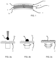
- Fig.1 diagrammatically shows a composite mold 1 according to an exemplary embodiment of the invention, which particularly comprises:
- the Applicant has established that both the film 4 and the underlying first microstructured inner surface 2a of the mineral first outer mold part 2 experience no damage.
- thermoset article such as a lens substrate configured to control myopia
- the thickness of the organic molding film 4 preferably ranges from 1/10 to 1/100 of the average amplitude of the microstructured inner surface 2a of the mineral first outer mold part 2, which allows not to affect the optics of the microstructure.
- the organic molding film 4 is selected to be hydrophobic, preferably exhibiting a water contact angle greater than 120°at least on its microstructured inner surface designed to be in contact with the thermosetting material 6 to be cast, the low surface tension of the film 4 enabling to easily demold the casted and cured article.
- the film 4 is further selected to have a thickness of between 10 nm and 500 ⁇ m, to be able to replicate the original microstructure on the mineral inner surface 2a at a high fidelity.
- the film 4 is furthermore selected to exhibit a medium adhesion with the mineral first outer mold part 2 (e.g. of mineral glass), to maintain a long-term production duration, so as to be easily detachable from the mineral first outer mold part 2 to repair or clean the same.
- the mineral first outer mold part 2 e.g. of mineral glass
- the film 4 preferably exhibits a medium Young modulus (of between 100 MPa and 4000 MPa) to protect the mineral first outer mold part 2 from impacts.
- Example 1 PDMS-based molding film applied by spin coating:
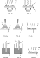
- the PDMS film 4 was prepared by spin coating and then curing, as explained above with reference to figures 2a-2d . Specifically, the PDMS mix 4a was poured over the microstructured inner surface 2a of a mineral glass first outer mold part 2 which had beforehand been treated with plasma, and then spin-coated thereon.
- the spin coating (i.e. spinning) speed and duration were both adjusted to reach the targeted thickness for the final cured film 4.
- the spinning speed By increasing the spinning speed, a plurality of films each with a thickness of between 10-100 ⁇ m were obtained, which proved to very well replicate the microstructure profile of the mineral glass inner surface at a high fidelity.
- the high replication fidelity of the microstructure profile may also be achieved by controlling the PDMS viscosity, tweaking shrinkage and microstructure shape design, and/or by using a mask to selectively cure the PDMS and wash-off the uncured part afterwards.
- the PDMS precursor film was further crosslinked after being mixed with the curing agent, and thus became a hydrophobic elastomeric film, which modulus/hardness was adjusted by varying the PDMS crosslinking degree.
- the Young modulus of the PDMS film was controlled by varying the curing agent weight ratio, and thus the crosslinking degree of the PDMS in the cured film.
- the noncrosslinked PDMS may be almost liquid or semi-solid, in case of a low or high number of repeating units, respectively.
- thermosetting lens substrates 6 of names Orma ® (homopolymer of diethylene glycol bis(allyl carbonate), and "MR7", “MR8, "1.74" (polythiourethane).
- the resulting lens substrates were easily demolded, and incorporated the replicated microstructure with a high fidelity, whilst the inner surface 2a of the mineral glass first outer mold part 2 was preserved, since it had been protected during the casting and curing steps by the film 4, which thus acted as a protective shield.
- the PDMS advantageously remained liquid at room temperature for many hours, even when mixed with the crosslinking agent, and that the PDMS was able to flow into the microstructure at high resolutions, also providing a precise control of the film thickness. With some optimization, it should therefore be possible to flow into microstructures of a few nanometers. Hence an easy and satisfactory moldability of the original microstructure.
- the PDMS film was easy to bond to the mineral glass of the first molding part 2, after this mineral glass had been treated with plasma, and that it provided an excellent releasability therefrom due to its low surface tension.
- the PDMS was particularly advantageous, since it exhibits an excellent chemical resistance to many solvents, such as, but not limited to, methanol, glycerol, propanol, acetone and pyridine.
- Example 2 Polyurethane rubber-based molding film applied by spin coating:
- the polyurethane rubber film 4 was prepared by dropping the thus prepared polymeric solution on the mineral glass first outer molt part 2 and spin-coated as disclosed above with reference to figures 2a-2c , to form a thin layer of between 10 ⁇ m and 100 ⁇ m, depending on the spin coater spinning speed.
- the thus prepared glass insert was put into an oven, to cure the polyurethane thin precursor layer 4a according to figure 2d , so as to obtain the film 4.
- Example 3 Thiol-ene thermoset-based molding film applied by spin coating:
- NOA 61 was spin-coated at 4000 rpm for 30 s, with a final thickness of 60 ⁇ m.
- the spin-coated solution was then UV-cured during 10 minutes under a high wattage UV lamp (Dymax ® 5000EC of 400 W), at an average intensity of 48 mW /cm 2 .
- the cured film 4 was left for stabilization at 60°C for 15 hours.
- Example 4 Fluoropolymer-based molding film applied by spin coating:
- the fluoropolymer film 4 was prepared by dropping the thus prepared polymeric solution on the mineral glass first outer mold part 2 and spin-coated as disclosed above with reference to figures 2a-2c , to form a thin precursor layer for the film 4.
- Acetone was evaporated during spin coating according to the solvent evaporation step of figure 2e , so that a thin layer of THV 220G was formed on the mineral glass first outer mold part 2, with a final thickness for the film 4 of between 10 ⁇ m and 100 ⁇ m.
- Example 5 TPU-based molding film applied by micro-thermoforming:
- Each TPU-based film 4 reached a final thickness of between 1 ⁇ m and 100 ⁇ m.
- Example 6 PDMS-based molding film applied by spray coating:
- an airbrush with a medium nozzle was held above the mineral glass first outer mold part 2, and droplets of the PDMS solution were sprayed under compressed nitrogen.
- the mineral glass first outer mold part 2 was rotated during spray coating, to achieve a more uniform thickness.
- a PDMS liquid film 4a was thus formed and its thickness was controlled particularly by spraying duration, pressure, rotation speed of the mold part 2.
- the PDMS liquid film 4a was then cured under heat, and/or UV, to obtain the film 4 with a final thickness of between 1 ⁇ m and 100 ⁇ m.
- Example 7 PDMS-based molding film applied by dip coating:
- the mineral glass first outer mold part 2 was dipped into this PDMS-OH solution and withdrawn for a few cycles, until a liquid precursor film 4a was formed at the required thickness.
- a solid hydrophobic film 4 was obtained after curing this liquid film 4a under heat and/or UV, with a a final thickness of between 1 ⁇ m and 100 ⁇ m.
- Example 8 Hydrophobic surface treatment for a polymeric molding film:
- This mold release agent is thus particularly usable to be spray-coated on a fluoropolymer, but also on reactive polysiloxanes, PVAs (polyvinyl alcohols), waxes and silicone oils, in a non-limiting manner.
- this hydrophobic surface treatment process may also be applied to a hydrophilic or less hydrophobic film by another coating technique, such as spin coating or dip coating, to obtain the desired hydrophobic molding film.
Landscapes
- Engineering & Computer Science (AREA)
- Mechanical Engineering (AREA)
- Health & Medical Sciences (AREA)
- Manufacturing & Machinery (AREA)
- Ophthalmology & Optometry (AREA)
- Casting Or Compression Moulding Of Plastics Or The Like (AREA)
- Moulds For Moulding Plastics Or The Like (AREA)
- Eyeglasses (AREA)
- Materials For Medical Uses (AREA)
Claims (15)
- Verbundform (1) zum Herstellen eines wärmehärtbaren optischen Artikels, der als ein ophthalmisches Linsensubstrat verwendbar ist und eine mikrostrukturierte Hauptoberfläche umfasst, durch Gießen eines wärmehärtenden Materials (6) in einen Formhohlraum (5), die Verbundform (1) Folgendes umfassend:- ein mineralisches erstes äußeres Formteil (2) mit einer ersten Innenfläche (2a), und- eine organische Formfolie (4), die lösbar mit der ersten Innenfläche (2a) verbunden ist und ein mikrostrukturiertes Muster aufweist, das eingerichtet ist, um die mikrostrukturierte Hauptoberfläche nach Gießen des wärmehärtenden Materials (6) in Kontakt mit der organischen Formfolie (4) unmittelbar auszubilden, wobei die Folie sowohl von dem mineralischen ersten äußeren Formteil als auch von dem gegossenen wärmehärtenden Material ablösbar ist,wobei die organische Formfolie (4) mindestens auf dem mikrostrukturierten Muster hydrophob ist und eine Dicke zwischen 10 nm und 500 µm aufweist.
- Verbundform (1) nach Anspruch 1, wobei die organische Formfolie (4):- mindestens auf dem mikrostrukturierten Muster einen Wasserkontaktwinkel größer 100°, vorzugsweise größer 110°, vorzugsweise größer 120° zeigt, und/oder- eine Dicke zwischen 1 µm und 100 µm aufweist.
- Verbundform (1) nach einem der vorhergehenden Ansprüche, wobei die organische Formfolie (4) auf mindestens einem Polymer basiert, das ausgewählt ist aus Elastomeren, thermoplastischen Polymeren und wärmehärtbaren Polymeren und vorzugsweise einen Young-Modul, gemessen nach ASTM D882-12, zwischen 100 MPa und 4000 MPa aufweist,
und wobei die organische Formfolie (4) einschichtig oder mehrschichtig ist und auf dem mikrostrukturierten Muster und gegebenenfalls auch durch die Dicke der organischen Formfolie (4) hydrophob ist. - Verbundform (1) nach Anspruch 3, wobei die organische Formfolie (4) auf mindestens einem vernetzten Elastomer basiert, das vorzugsweise ausgewählt ist aus Silikonkautschuken, wie beispielsweise zweikomponentigen Polydimethylsiloxanen (PDMS), und aus Polyurethankautschuken, wie beispielsweise zweikomponentigen flüssigen Urethankautschuken.
- Verbundform (1) nach Anspruch 3, wobei die organische Formfolie (4) auf mindestens einem wärmehärtbaren Polymer basiert, das vorzugsweise ausgewählt ist aus Thiol-En-Duromeren, wie beispielsweise einkomponentigen flüssigen Photopolymerklebstoffen, und aus wärmehärtbaren Polyurethanen.
- Verbundform (1) nach Anspruch 3, wobei die organische Formfolie (4) auf mindestens einem thermoplastischen Polymer basiert, das vorzugsweise ausgewählt ist aus fluorierten Polymeren, wie beispielsweise Terpolymeren von Tetrafluorethylen, Hexafluorpropylen und Vinylidenfluorid, und aus thermoplastischen Polyurethanen (TPU).
- Verbundform (1) nach einem der vorhergehenden Ansprüche, wobei das mineralische erste äußere Formteil (2), das beispielsweise aus Mineralglas hergestellt ist, die erste Innenfläche (2a) aufweist, die eine Mikrostruktur umfasst, auf die eine erste Fläche der organischen Formfolie (4) ohne einen Klebstoff dazwischen lösbar gebondet ist, wobei die organische Formfolie (4) sich an die Mikrostruktur auf der ersten Fläche anpasst und eine gegenüberliegende zweite Fläche aufweist, die das mikrostrukturierte Muster ausbildet; und
wobei die Verbundform (1) weiterhin ein mineralisches zweites äußeres Formteil (3) umfasst, das eine zweite Innenfläche (3a) gegenüber der ersten Innenfläche (2a) aufweist, wobei der Formhohlraum (5) zwischen der organischen Formfolie (4) und der zweiten Innenfläche (3a) definiert ist. - Verbundform (1) nach Anspruch 7, wobei die erste Innenfläche (2a) des mineralischen ersten äußeren Formteils (2) die erste Innenfläche (2a) aufweist, die konkav ist, und wobei die Dicke der organischen Formfolie (4) im Bereich von 1/10 bis 1/100 der durchschnittlichen Amplitude der Mikrostruktur des mineralischen ersten äußeren Formteils (2) liegt.
- Verfahren zum Herstellen eines wärmehärtenden optischen Artikels, der als ein ophthalmisches Linsensubstrat verwendbar ist und der eine mikrostrukturierte Hauptoberfläche umfasst, die zum Beispiel eingerichtet ist, um Myopie zu beherrschen, wobei das Verfahren Folgendes umfasst:a) Gießen eines wärmehärtenden Materials (6) in einen Formhohlraum (5) einer Verbundform (1) nach einem der vorhergehenden Ansprüche, so dass das wärmehärtende Material (6) die organische Formfolie (4) und eine zweite Innenfläche (3a) eines mineralischen zweiten äußeren Formteils (3), die der ersten Innenfläche (2a) gegenüberliegt, berührt, ohne die erste Innenfläche (2a) zu berühren,b) Härten des wärmehärtenden Materials (6), das in den Formhohlraum (5) gegossen wurde; undc) aus der Form Herausnehmen des in Schritt b) erlangten geformten wärmehärtbaren Materials, umfassend Lösen des geformten wärmehärtbaren Materials von der organischen Formfolie (4), so dass das mikrostrukturierte Muster der organischen Formfolie (4) die mikrostrukturierte Hauptoberfläche des erlangten wärmehärtbaren optischen Artikels unmittelbar ausbildet.
- Verfahren nach Anspruch 9, wobei die organische Formfolie (4) während des Gießschritts a) einem Angriff von dem wärmehärtenden Material (6) widersteht, das ausgewählt ist aus:- Cycloolefin-Copolymeren, wie beispielsweise Ethylen/Norbornen- oder Ethylen/Cyclopentadien-Copolymeren,- Homopolymeren und Copolymeren von Allylcarbonaten linearer oder verzweigter aliphatischer oder aromatischer Polyole, wie beispielsweise Homopolymeren von Diethylenglykolbisallylcarbonat,- Homopolymeren und Copolymeren von (Meth)Acrylsäure und deren Estern, die gegebenenfalls von Bisphenol A abgeleitet sind,- Homopolymeren und Copolymeren von Thio(meth)acrylsäure und deren Estern,- Homopolymeren und Copolymeren von Allylestern, die gegebenenfalls von Bisphenol A oder Phthalsäuren abgeleitet sind, und Allylaromaten, wie beispielsweise Styrol,- Copolymeren von Urethan und Thiourethan,- Homopolymeren und Copolymeren von Epoxid und- Homopolymeren und Copolymeren von Sulfid, Disulfid und Episulfid.
- Verfahren zum Erlangen einer Verbundform (1) nach einem der Ansprüche 1 bis 8, wobei das Verfahren Folgendes umfasst:A) Bereitstellen einer Polymerzusammensetzung, die entweder hydrophob ist oder mit einer hydrophoben Oberflächenschicht beschichtet ist und die in der Lage ist, die organische Formfolie (4) so auszubilden, dass sie lösbar mit dem mineralischen ersten äußeren Formteil (2) gebondet ist, wobei die Polymerzusammensetzung einem Angriff des zu gießenden wärmehärtenden Materials (6) widerstehen kann,B) Aufbringen der Polymerzusammensetzung auf die Innenfläche (2a) des mineralischen ersten äußeren Formteils (2), um eine Vorläuferschicht (4a) für die organische Formfolie (4) auszubilden, undC) Behandeln der aufgebrachten Vorläuferschicht (4a), um die organische Formfolie (4) auszubilden, welche die Dicke zwischen 10 nm und 500 µm und eine Oberflächenspannung aufweist, die in der Lage ist, den gegossenen und gehärteten wärmehärtbaren optischen Artikel davon zu lösen.
- Verfahren nach Anspruch 11, wobei die Innenfläche (2a) des mineralischen ersten äußeren Formteils (2) aus Mineralglas ausgebildet ist und eine Mikrostruktur umfasst, auf welche die organische Formfolie (4) in den Schritten B) und C) konform gebondet wird, um das mikrostrukturierte Muster auszubilden.
- Verfahren nach Anspruch 12, wobei die Polymerzusammensetzung aus einer Lösung besteht, die ein Lösemittel und mindestens ein Polymer umfasst, das ausgewählt ist aus Elastomeren, thermoplastischen Polymeren und wärmehärtbaren Polymeren, und wobei Schritt B) Beschichten der Lösung auf die Innenfläche (2a) des mineralischen ersten äußeren Formteils (2) vorzugsweise durch Schleuderbeschichten, Sprühbeschichten oder Tauchbeschichten umfasst.
- Verfahren nach Anspruch 13, wobei Schritt C) Folgendes umfasst:- Vernetzen der Vorläuferschicht (4a) beispielsweise mit Wärme und/oder UV-Strahlung, vorzugsweise wenn das mindestens eine Polymer aus Elastomeren und wärmehärtbaren Polymeren ausgewählt ist, oder- Verdampfen des Lösemittels, vorzugsweise wenn das mindestens eine Polymer aus thermoplastischen Polymeren ausgewählt ist und in Schritt B) schleuderbeschichtet wird.
- Verfahren nach Anspruch 12, wobei, wenn die Polymerzusammensetzung frei von einem Lösemittel ist und vorzugsweise wenn das mindestens eine Polymer ausgewählt ist aus thermoplastischen Polymeren, die Schritte B) und C) Mikrothermoformen der Polymerzusammensetzung unter Verwendung von Druck und/oder Vakuum durch Kompression gegen die Mikrostruktur der Innenfläche (2a) des mineralischen ersten äußeren Formteils (2) umfassen.
Priority Applications (7)
| Application Number | Priority Date | Filing Date | Title |
|---|---|---|---|
| EP21305684.9A EP4094932B1 (de) | 2021-05-26 | 2021-05-26 | Verbundform zur herstellung eines mikrostrukturierten wärmehärtbaren artikels, herstellungsverfahren und verfahren zur herstellung der form |
| CN202280036019.4A CN117337232A (zh) | 2021-05-26 | 2022-05-25 | 用于制造微结构化热固性制品的复合模具、制造方法以及获得该模具的方法 |
| US18/563,150 US12539680B2 (en) | 2021-05-26 | 2022-05-25 | Composite mold for manufacturing a microstructured thermoset article, manufacturing method and method for obtaining the mold |
| KR1020237039397A KR20240013109A (ko) | 2021-05-26 | 2022-05-25 | 미세구조화된 열경화성 물품을 제조하기 위한 복합재 몰드, 제조 방법 및 몰드의 수득 방법 |
| PCT/EP2022/064212 WO2022248557A1 (en) | 2021-05-26 | 2022-05-25 | Composite mold for manufacturing a microstructured thermoset article, manufacturing method and method for obtaining the mold |
| JP2023572985A JP2024520466A (ja) | 2021-05-26 | 2022-05-25 | 微細構造化熱硬化性物品を製造するための複合型、製造方法及び型を得るための方法 |
| BR112023023889A BR112023023889A2 (pt) | 2021-05-26 | 2022-05-25 | Molde compósito para fabricação de um artigo termoendurecido microstruturado, método de fabricação e método de obtenção do molde |
Applications Claiming Priority (1)
| Application Number | Priority Date | Filing Date | Title |
|---|---|---|---|
| EP21305684.9A EP4094932B1 (de) | 2021-05-26 | 2021-05-26 | Verbundform zur herstellung eines mikrostrukturierten wärmehärtbaren artikels, herstellungsverfahren und verfahren zur herstellung der form |
Publications (2)
| Publication Number | Publication Date |
|---|---|
| EP4094932A1 EP4094932A1 (de) | 2022-11-30 |
| EP4094932B1 true EP4094932B1 (de) | 2024-09-04 |
Family
ID=76325472
Family Applications (1)
| Application Number | Title | Priority Date | Filing Date |
|---|---|---|---|
| EP21305684.9A Active EP4094932B1 (de) | 2021-05-26 | 2021-05-26 | Verbundform zur herstellung eines mikrostrukturierten wärmehärtbaren artikels, herstellungsverfahren und verfahren zur herstellung der form |
Country Status (7)
| Country | Link |
|---|---|
| US (1) | US12539680B2 (de) |
| EP (1) | EP4094932B1 (de) |
| JP (1) | JP2024520466A (de) |
| KR (1) | KR20240013109A (de) |
| CN (1) | CN117337232A (de) |
| BR (1) | BR112023023889A2 (de) |
| WO (1) | WO2022248557A1 (de) |
Families Citing this family (1)
| Publication number | Priority date | Publication date | Assignee | Title |
|---|---|---|---|---|
| WO2025040706A1 (de) * | 2023-08-21 | 2025-02-27 | Fraunhofer-Gesellschaft zur Förderung der angewandten Forschung eingetragener Verein | Substrat mit durch mikrostrukturen und/oder nanostrukturen abgegrenzter fläche |
Family Cites Families (28)
| Publication number | Priority date | Publication date | Assignee | Title |
|---|---|---|---|---|
| US5096626A (en) * | 1988-06-10 | 1992-03-17 | Asahi Kogaku Kogyo Kabushiki Kaisha | Process of molding a coated plastic lens |
| JP3323614B2 (ja) * | 1993-12-27 | 2002-09-09 | 株式会社日立製作所 | 透明部材とその製造方法 |
| FR2772302B1 (fr) | 1997-12-11 | 2000-01-21 | Essilor Int | Procede d'obtention d'une lentille ophtalmique comportant une microstructure utilitaire en surface et lentilles ophtalmiques ainsi obtenues |
| JP2000326348A (ja) * | 1999-05-21 | 2000-11-28 | Asahi Optical Co Ltd | レンズ成形型,その作製方法,及びレンズ製造方法 |
| US20050140033A1 (en) * | 2003-12-31 | 2005-06-30 | Essilor International Compagnie Generale D'optique | Process for making a coated optical article free of visible fining lines |
| JP2008162191A (ja) * | 2006-12-28 | 2008-07-17 | Asahi Glass Co Ltd | 光学素子の製造方法 |
| CN103298603B (zh) * | 2011-01-04 | 2017-01-18 | 埃西勒国际通用光学公司 | 制造具有结构化表面的眼科透镜的方法 |
| KR101475827B1 (ko) * | 2013-12-17 | 2014-12-23 | 인하대학교 산학협력단 | 패턴된 소수성 박막을 이용한 엘이디 패키지용 렌즈 형성 방법 |
| US20190013496A1 (en) * | 2015-12-31 | 2019-01-10 | Sabic Global Technologies B.V. | Multifunctional hierarchical nano and microlens for enhancing extraction efficiency of oled lighting |
| JP6493628B2 (ja) * | 2017-03-24 | 2019-04-03 | 住友ベークライト株式会社 | モールド成形用離型フィルム及びモールド成形方法 |
| JP7098864B2 (ja) * | 2017-07-05 | 2022-07-12 | 学校法人東京理科大学 | モスアイパターン付き物品の製造方法、及びモスアイパターン付き反転型の製造方法 |
| EP3441799A1 (de) * | 2017-08-09 | 2019-02-13 | Essilor International | Optischer artikel mit einem substrat mit eingebetteten partikeln zur abrieb- und/oder kratzfestigkeitsverbesserung |
| EP3441798A1 (de) * | 2017-08-09 | 2019-02-13 | Essilor International | Optischer artikel mit einem substrat mit eingebetteten partikeln zur lichtübertragungserhöhung |
| JP2019088765A (ja) * | 2017-11-10 | 2019-06-13 | 凸版印刷株式会社 | 貼付剤用支持体フィルム、積層体及び貼付剤 |
| WO2019124353A1 (ja) * | 2017-12-19 | 2019-06-27 | ホヤ レンズ タイランド リミテッド | 眼鏡レンズ成形型の製造方法及び眼鏡レンズの製造方法 |
| HUE062437T2 (hu) | 2018-03-01 | 2023-11-28 | Essilor Int | Lencseelem |
| ES3047100T3 (en) * | 2018-06-08 | 2025-12-03 | Essilor Int | Determining method for an ophthalmic lens with targeted transmission spectrum |
| KR102194832B1 (ko) * | 2019-01-03 | 2020-12-23 | 부산대학교 산학협력단 | 렌즈 표면 나노구조층의 제조 방법 |
| JP7347803B2 (ja) * | 2019-03-20 | 2023-09-20 | 株式会社コバヤシ | 金型と離型フィルムとの組合せ、離型フィルム、金型、及び成形体の製造方法 |
| EP3760423A1 (de) * | 2019-07-02 | 2021-01-06 | Essilor International | Verfahren zur herstellung optischer linsen unter verwendung von 3d-gedruckten funktionalen wafern |
| EP3760422A1 (de) * | 2019-07-02 | 2021-01-06 | Essilor International | Verfahren zum umspritzen mit wärmezyklen zur herstellung von optischen linsen unter verwendung von 3d-gedruckten funktionalen wafern |
| EP3895879A1 (de) * | 2020-04-14 | 2021-10-20 | Essilor International | Giessen einer linse mit oberflächenmikrostrukturen |
| EP3910411B1 (de) * | 2020-05-13 | 2025-04-02 | Essilor International | Primer für brillengläser |
| EP4119321A1 (de) * | 2021-07-13 | 2023-01-18 | Essilor International | Verfahren zur herstellung mikrostrukturierter einsätze zum spritzgiessen |
| EP4122687A1 (de) * | 2021-07-19 | 2023-01-25 | Essilor International | Zusammengesetzter formeinsatz zur herstellung mikrostrukturierter linsen |
| WO2023001780A1 (en) * | 2021-07-19 | 2023-01-26 | Essilor International | Mold for manufacturing a thermoset optical article, method for manufacturing the mold and method for manufacturing the thermoset optical article |
| EP4194932A1 (de) * | 2021-12-10 | 2023-06-14 | Essilor International | Ophthalmische linse und verfahren zur herstellung einer ophthalmischen linse |
| EP4197765A1 (de) * | 2021-12-16 | 2023-06-21 | Essilor International | Verfahren zum einkapseln einer mikrostrukturierten linse durch pipc |
-
2021
- 2021-05-26 EP EP21305684.9A patent/EP4094932B1/de active Active
-
2022
- 2022-05-25 JP JP2023572985A patent/JP2024520466A/ja active Pending
- 2022-05-25 BR BR112023023889A patent/BR112023023889A2/pt unknown
- 2022-05-25 WO PCT/EP2022/064212 patent/WO2022248557A1/en not_active Ceased
- 2022-05-25 US US18/563,150 patent/US12539680B2/en active Active
- 2022-05-25 KR KR1020237039397A patent/KR20240013109A/ko active Pending
- 2022-05-25 CN CN202280036019.4A patent/CN117337232A/zh active Pending
Also Published As
| Publication number | Publication date |
|---|---|
| US20240227332A1 (en) | 2024-07-11 |
| JP2024520466A (ja) | 2024-05-24 |
| EP4094932A1 (de) | 2022-11-30 |
| KR20240013109A (ko) | 2024-01-30 |
| CN117337232A (zh) | 2024-01-02 |
| BR112023023889A2 (pt) | 2024-02-06 |
| WO2022248557A1 (en) | 2022-12-01 |
| US12539680B2 (en) | 2026-02-03 |
Similar Documents
| Publication | Publication Date | Title |
|---|---|---|
| US12405403B2 (en) | Lens with surface microstructures encapsulated by a self-stratified hard coat | |
| CN112888973B (zh) | 包含光学元件的改进的光学制品及其制造方法 | |
| KR101603291B1 (ko) | 프레넬 렌즈를 형성하는 표면의 코팅 공정 | |
| US20240316846A1 (en) | Method for fabricating microstructured inserts for injection molding | |
| JP2024545491A (ja) | 眼用レンズ及び眼用レンズを形成する方法 | |
| CN115413327B (zh) | 用于并入眼科镜片的含光学微结构的层压件 | |
| KR20230004481A (ko) | 두꺼운 저굴절률 하드 코팅으로 캡슐화된 표면 마이크로구조물을 갖는 렌즈 | |
| US12539680B2 (en) | Composite mold for manufacturing a microstructured thermoset article, manufacturing method and method for obtaining the mold | |
| JP2010224205A (ja) | 接合光学素子及びその製造方法 | |
| CN102712149B (zh) | 菲涅耳透镜涂布方法 | |
| CN118382823A (zh) | 具有耐磨性的图案化镜片 | |
| JP7822558B2 (ja) | 透明樹脂積層体の成形方法 | |
| JP2009248483A (ja) | 複合光学素子の製造方法 | |
| TH2301007312A (th) | แม่พิมพ์คอมโพสิตสำหรับผลิตผลิตภัณฑ์ชนิดเทอร์โมเซตที่มีโครงสร้างจุลภาค, วิธีการผลิตและวิธีการสำหรับทำให้ได้แม่พิมพ์ | |
| CN120187578A (zh) | 用于制造眼镜镜片的模具设备和相关方法 | |
| JPWO2022248557A5 (de) | ||
| JP2006220816A (ja) | 光学素子の製造方法 |
Legal Events
| Date | Code | Title | Description |
|---|---|---|---|
| PUAI | Public reference made under article 153(3) epc to a published international application that has entered the european phase |
Free format text: ORIGINAL CODE: 0009012 |
|
| STAA | Information on the status of an ep patent application or granted ep patent |
Free format text: STATUS: THE APPLICATION HAS BEEN PUBLISHED |
|
| AK | Designated contracting states |
Kind code of ref document: A1 Designated state(s): AL AT BE BG CH CY CZ DE DK EE ES FI FR GB GR HR HU IE IS IT LI LT LU LV MC MK MT NL NO PL PT RO RS SE SI SK SM TR |
|
| STAA | Information on the status of an ep patent application or granted ep patent |
Free format text: STATUS: REQUEST FOR EXAMINATION WAS MADE |
|
| 17P | Request for examination filed |
Effective date: 20230510 |
|
| RBV | Designated contracting states (corrected) |
Designated state(s): AL AT BE BG CH CY CZ DE DK EE ES FI FR GB GR HR HU IE IS IT LI LT LU LV MC MK MT NL NO PL PT RO RS SE SI SK SM TR |
|
| P01 | Opt-out of the competence of the unified patent court (upc) registered |
Effective date: 20230525 |
|
| GRAP | Despatch of communication of intention to grant a patent |
Free format text: ORIGINAL CODE: EPIDOSNIGR1 |
|
| STAA | Information on the status of an ep patent application or granted ep patent |
Free format text: STATUS: GRANT OF PATENT IS INTENDED |
|
| RIC1 | Information provided on ipc code assigned before grant |
Ipc: B29K 101/10 20060101ALN20240404BHEP Ipc: B29L 11/00 20060101ALN20240404BHEP Ipc: B29C 39/26 20060101ALI20240404BHEP Ipc: B29C 33/62 20060101ALI20240404BHEP Ipc: B29C 33/58 20060101ALI20240404BHEP Ipc: B29C 39/02 20060101ALI20240404BHEP Ipc: B29D 11/00 20060101AFI20240404BHEP |
|
| INTG | Intention to grant announced |
Effective date: 20240417 |
|
| GRAS | Grant fee paid |
Free format text: ORIGINAL CODE: EPIDOSNIGR3 |
|
| GRAA | (expected) grant |
Free format text: ORIGINAL CODE: 0009210 |
|
| STAA | Information on the status of an ep patent application or granted ep patent |
Free format text: STATUS: THE PATENT HAS BEEN GRANTED |
|
| AK | Designated contracting states |
Kind code of ref document: B1 Designated state(s): AL AT BE BG CH CY CZ DE DK EE ES FI FR GB GR HR HU IE IS IT LI LT LU LV MC MK MT NL NO PL PT RO RS SE SI SK SM TR |
|
| REG | Reference to a national code |
Ref country code: GB Ref legal event code: FG4D |
|
| REG | Reference to a national code |
Ref country code: CH Ref legal event code: EP |
|
| REG | Reference to a national code |
Ref country code: IE Ref legal event code: FG4D |
|
| REG | Reference to a national code |
Ref country code: DE Ref legal event code: R096 Ref document number: 602021018265 Country of ref document: DE |
|
| REG | Reference to a national code |
Ref country code: LT Ref legal event code: MG9D |
|
| REG | Reference to a national code |
Ref country code: NL Ref legal event code: MP Effective date: 20240904 |
|
| PG25 | Lapsed in a contracting state [announced via postgrant information from national office to epo] |
Ref country code: NO Free format text: LAPSE BECAUSE OF FAILURE TO SUBMIT A TRANSLATION OF THE DESCRIPTION OR TO PAY THE FEE WITHIN THE PRESCRIBED TIME-LIMIT Effective date: 20241204 |
|
| PG25 | Lapsed in a contracting state [announced via postgrant information from national office to epo] |
Ref country code: PL Free format text: LAPSE BECAUSE OF FAILURE TO SUBMIT A TRANSLATION OF THE DESCRIPTION OR TO PAY THE FEE WITHIN THE PRESCRIBED TIME-LIMIT Effective date: 20240904 Ref country code: GR Free format text: LAPSE BECAUSE OF FAILURE TO SUBMIT A TRANSLATION OF THE DESCRIPTION OR TO PAY THE FEE WITHIN THE PRESCRIBED TIME-LIMIT Effective date: 20241205 Ref country code: FI Free format text: LAPSE BECAUSE OF FAILURE TO SUBMIT A TRANSLATION OF THE DESCRIPTION OR TO PAY THE FEE WITHIN THE PRESCRIBED TIME-LIMIT Effective date: 20240904 |
|
| PG25 | Lapsed in a contracting state [announced via postgrant information from national office to epo] |
Ref country code: BG Free format text: LAPSE BECAUSE OF FAILURE TO SUBMIT A TRANSLATION OF THE DESCRIPTION OR TO PAY THE FEE WITHIN THE PRESCRIBED TIME-LIMIT Effective date: 20240904 |
|
| PG25 | Lapsed in a contracting state [announced via postgrant information from national office to epo] |
Ref country code: LV Free format text: LAPSE BECAUSE OF FAILURE TO SUBMIT A TRANSLATION OF THE DESCRIPTION OR TO PAY THE FEE WITHIN THE PRESCRIBED TIME-LIMIT Effective date: 20240904 |
|
| PG25 | Lapsed in a contracting state [announced via postgrant information from national office to epo] |
Ref country code: HR Free format text: LAPSE BECAUSE OF FAILURE TO SUBMIT A TRANSLATION OF THE DESCRIPTION OR TO PAY THE FEE WITHIN THE PRESCRIBED TIME-LIMIT Effective date: 20240904 |
|
| PG25 | Lapsed in a contracting state [announced via postgrant information from national office to epo] |
Ref country code: ES Free format text: LAPSE BECAUSE OF FAILURE TO SUBMIT A TRANSLATION OF THE DESCRIPTION OR TO PAY THE FEE WITHIN THE PRESCRIBED TIME-LIMIT Effective date: 20240904 Ref country code: RS Free format text: LAPSE BECAUSE OF FAILURE TO SUBMIT A TRANSLATION OF THE DESCRIPTION OR TO PAY THE FEE WITHIN THE PRESCRIBED TIME-LIMIT Effective date: 20241204 |
|
| PG25 | Lapsed in a contracting state [announced via postgrant information from national office to epo] |
Ref country code: RS Free format text: LAPSE BECAUSE OF FAILURE TO SUBMIT A TRANSLATION OF THE DESCRIPTION OR TO PAY THE FEE WITHIN THE PRESCRIBED TIME-LIMIT Effective date: 20241204 Ref country code: PL Free format text: LAPSE BECAUSE OF FAILURE TO SUBMIT A TRANSLATION OF THE DESCRIPTION OR TO PAY THE FEE WITHIN THE PRESCRIBED TIME-LIMIT Effective date: 20240904 Ref country code: NO Free format text: LAPSE BECAUSE OF FAILURE TO SUBMIT A TRANSLATION OF THE DESCRIPTION OR TO PAY THE FEE WITHIN THE PRESCRIBED TIME-LIMIT Effective date: 20241204 Ref country code: LV Free format text: LAPSE BECAUSE OF FAILURE TO SUBMIT A TRANSLATION OF THE DESCRIPTION OR TO PAY THE FEE WITHIN THE PRESCRIBED TIME-LIMIT Effective date: 20240904 Ref country code: HR Free format text: LAPSE BECAUSE OF FAILURE TO SUBMIT A TRANSLATION OF THE DESCRIPTION OR TO PAY THE FEE WITHIN THE PRESCRIBED TIME-LIMIT Effective date: 20240904 Ref country code: GR Free format text: LAPSE BECAUSE OF FAILURE TO SUBMIT A TRANSLATION OF THE DESCRIPTION OR TO PAY THE FEE WITHIN THE PRESCRIBED TIME-LIMIT Effective date: 20241205 Ref country code: FI Free format text: LAPSE BECAUSE OF FAILURE TO SUBMIT A TRANSLATION OF THE DESCRIPTION OR TO PAY THE FEE WITHIN THE PRESCRIBED TIME-LIMIT Effective date: 20240904 Ref country code: ES Free format text: LAPSE BECAUSE OF FAILURE TO SUBMIT A TRANSLATION OF THE DESCRIPTION OR TO PAY THE FEE WITHIN THE PRESCRIBED TIME-LIMIT Effective date: 20240904 Ref country code: BG Free format text: LAPSE BECAUSE OF FAILURE TO SUBMIT A TRANSLATION OF THE DESCRIPTION OR TO PAY THE FEE WITHIN THE PRESCRIBED TIME-LIMIT Effective date: 20240904 |
|
| REG | Reference to a national code |
Ref country code: AT Ref legal event code: MK05 Ref document number: 1719949 Country of ref document: AT Kind code of ref document: T Effective date: 20240904 |
|
| PG25 | Lapsed in a contracting state [announced via postgrant information from national office to epo] |
Ref country code: NL Free format text: LAPSE BECAUSE OF FAILURE TO SUBMIT A TRANSLATION OF THE DESCRIPTION OR TO PAY THE FEE WITHIN THE PRESCRIBED TIME-LIMIT Effective date: 20240904 |
|
| PG25 | Lapsed in a contracting state [announced via postgrant information from national office to epo] |
Ref country code: IS Free format text: LAPSE BECAUSE OF FAILURE TO SUBMIT A TRANSLATION OF THE DESCRIPTION OR TO PAY THE FEE WITHIN THE PRESCRIBED TIME-LIMIT Effective date: 20250104 Ref country code: PT Free format text: LAPSE BECAUSE OF FAILURE TO SUBMIT A TRANSLATION OF THE DESCRIPTION OR TO PAY THE FEE WITHIN THE PRESCRIBED TIME-LIMIT Effective date: 20250106 |
|
| PG25 | Lapsed in a contracting state [announced via postgrant information from national office to epo] |
Ref country code: RO Free format text: LAPSE BECAUSE OF FAILURE TO SUBMIT A TRANSLATION OF THE DESCRIPTION OR TO PAY THE FEE WITHIN THE PRESCRIBED TIME-LIMIT Effective date: 20240904 Ref country code: SM Free format text: LAPSE BECAUSE OF FAILURE TO SUBMIT A TRANSLATION OF THE DESCRIPTION OR TO PAY THE FEE WITHIN THE PRESCRIBED TIME-LIMIT Effective date: 20240904 |
|
| PG25 | Lapsed in a contracting state [announced via postgrant information from national office to epo] |
Ref country code: EE Free format text: LAPSE BECAUSE OF FAILURE TO SUBMIT A TRANSLATION OF THE DESCRIPTION OR TO PAY THE FEE WITHIN THE PRESCRIBED TIME-LIMIT Effective date: 20240904 Ref country code: AT Free format text: LAPSE BECAUSE OF FAILURE TO SUBMIT A TRANSLATION OF THE DESCRIPTION OR TO PAY THE FEE WITHIN THE PRESCRIBED TIME-LIMIT Effective date: 20240904 |
|
| PG25 | Lapsed in a contracting state [announced via postgrant information from national office to epo] |
Ref country code: CZ Free format text: LAPSE BECAUSE OF FAILURE TO SUBMIT A TRANSLATION OF THE DESCRIPTION OR TO PAY THE FEE WITHIN THE PRESCRIBED TIME-LIMIT Effective date: 20240904 |
|
| PG25 | Lapsed in a contracting state [announced via postgrant information from national office to epo] |
Ref country code: SK Free format text: LAPSE BECAUSE OF FAILURE TO SUBMIT A TRANSLATION OF THE DESCRIPTION OR TO PAY THE FEE WITHIN THE PRESCRIBED TIME-LIMIT Effective date: 20240904 |
|
| REG | Reference to a national code |
Ref country code: DE Ref legal event code: R097 Ref document number: 602021018265 Country of ref document: DE |
|
| PGFP | Annual fee paid to national office [announced via postgrant information from national office to epo] |
Ref country code: DE Payment date: 20250529 Year of fee payment: 5 |
|
| PG25 | Lapsed in a contracting state [announced via postgrant information from national office to epo] |
Ref country code: DK Free format text: LAPSE BECAUSE OF FAILURE TO SUBMIT A TRANSLATION OF THE DESCRIPTION OR TO PAY THE FEE WITHIN THE PRESCRIBED TIME-LIMIT Effective date: 20240904 |
|
| PGFP | Annual fee paid to national office [announced via postgrant information from national office to epo] |
Ref country code: GB Payment date: 20250527 Year of fee payment: 5 |
|
| PLBE | No opposition filed within time limit |
Free format text: ORIGINAL CODE: 0009261 |
|
| STAA | Information on the status of an ep patent application or granted ep patent |
Free format text: STATUS: NO OPPOSITION FILED WITHIN TIME LIMIT |
|
| PGFP | Annual fee paid to national office [announced via postgrant information from national office to epo] |
Ref country code: IT Payment date: 20250521 Year of fee payment: 5 |
|
| PGFP | Annual fee paid to national office [announced via postgrant information from national office to epo] |
Ref country code: FR Payment date: 20250526 Year of fee payment: 5 |
|
| 26N | No opposition filed |
Effective date: 20250605 |
|
| PG25 | Lapsed in a contracting state [announced via postgrant information from national office to epo] |
Ref country code: SE Free format text: LAPSE BECAUSE OF FAILURE TO SUBMIT A TRANSLATION OF THE DESCRIPTION OR TO PAY THE FEE WITHIN THE PRESCRIBED TIME-LIMIT Effective date: 20240904 |
|
| REG | Reference to a national code |
Ref country code: CH Ref legal event code: H13 Free format text: ST27 STATUS EVENT CODE: U-0-0-H10-H13 (AS PROVIDED BY THE NATIONAL OFFICE) Effective date: 20251223 |
|
| PG25 | Lapsed in a contracting state [announced via postgrant information from national office to epo] |
Ref country code: LU Free format text: LAPSE BECAUSE OF NON-PAYMENT OF DUE FEES Effective date: 20250526 |
|
| PG25 | Lapsed in a contracting state [announced via postgrant information from national office to epo] |
Ref country code: CH Free format text: LAPSE BECAUSE OF NON-PAYMENT OF DUE FEES Effective date: 20250531 |
|
| REG | Reference to a national code |
Ref country code: BE Ref legal event code: MM Effective date: 20250531 |
|
| PG25 | Lapsed in a contracting state [announced via postgrant information from national office to epo] |
Ref country code: MC Free format text: LAPSE BECAUSE OF FAILURE TO SUBMIT A TRANSLATION OF THE DESCRIPTION OR TO PAY THE FEE WITHIN THE PRESCRIBED TIME-LIMIT Effective date: 20240904 |
|
| PG25 | Lapsed in a contracting state [announced via postgrant information from national office to epo] |
Ref country code: IE Free format text: LAPSE BECAUSE OF NON-PAYMENT OF DUE FEES Effective date: 20250526 |
|
| PG25 | Lapsed in a contracting state [announced via postgrant information from national office to epo] |
Ref country code: BE Free format text: LAPSE BECAUSE OF NON-PAYMENT OF DUE FEES Effective date: 20250531 |