EP4096510B1 - Appareil de mesure de la pression sanguine et ses procédés d'utilisation - Google Patents
Appareil de mesure de la pression sanguine et ses procédés d'utilisation Download PDFInfo
- Publication number
- EP4096510B1 EP4096510B1 EP21747357.8A EP21747357A EP4096510B1 EP 4096510 B1 EP4096510 B1 EP 4096510B1 EP 21747357 A EP21747357 A EP 21747357A EP 4096510 B1 EP4096510 B1 EP 4096510B1
- Authority
- EP
- European Patent Office
- Prior art keywords
- khz
- transducer
- blood vessel
- blood pressure
- frequency
- Prior art date
- Legal status (The legal status is an assumption and is not a legal conclusion. Google has not performed a legal analysis and makes no representation as to the accuracy of the status listed.)
- Active
Links
Images






Classifications
-
- A—HUMAN NECESSITIES
- A61—MEDICAL OR VETERINARY SCIENCE; HYGIENE
- A61B—DIAGNOSIS; SURGERY; IDENTIFICATION
- A61B5/00—Measuring for diagnostic purposes; Identification of persons
- A61B5/02—Detecting, measuring or recording for evaluating the cardiovascular system, e.g. pulse, heart rate, blood pressure or blood flow
- A61B5/021—Measuring pressure in heart or blood vessels
- A61B5/022—Measuring pressure in heart or blood vessels by applying pressure to close blood vessels, e.g. against the skin; Ophthalmodynamometers
-
- A—HUMAN NECESSITIES
- A61—MEDICAL OR VETERINARY SCIENCE; HYGIENE
- A61B—DIAGNOSIS; SURGERY; IDENTIFICATION
- A61B8/00—Diagnosis using ultrasonic, sonic or infrasonic waves
- A61B8/04—Measuring blood pressure
-
- A—HUMAN NECESSITIES
- A61—MEDICAL OR VETERINARY SCIENCE; HYGIENE
- A61B—DIAGNOSIS; SURGERY; IDENTIFICATION
- A61B8/00—Diagnosis using ultrasonic, sonic or infrasonic waves
- A61B8/06—Measuring blood flow
-
- A—HUMAN NECESSITIES
- A61—MEDICAL OR VETERINARY SCIENCE; HYGIENE
- A61B—DIAGNOSIS; SURGERY; IDENTIFICATION
- A61B8/00—Diagnosis using ultrasonic, sonic or infrasonic waves
- A61B8/08—Clinical applications
- A61B8/0858—Clinical applications involving measuring tissue layers, e.g. skin, interfaces
-
- A—HUMAN NECESSITIES
- A61—MEDICAL OR VETERINARY SCIENCE; HYGIENE
- A61B—DIAGNOSIS; SURGERY; IDENTIFICATION
- A61B8/00—Diagnosis using ultrasonic, sonic or infrasonic waves
- A61B8/08—Clinical applications
- A61B8/0891—Clinical applications for diagnosis of blood vessels
-
- A—HUMAN NECESSITIES
- A61—MEDICAL OR VETERINARY SCIENCE; HYGIENE
- A61B—DIAGNOSIS; SURGERY; IDENTIFICATION
- A61B8/00—Diagnosis using ultrasonic, sonic or infrasonic waves
- A61B8/42—Details of probe positioning or probe attachment to the patient
- A61B8/4209—Details of probe positioning or probe attachment to the patient by using holders, e.g. positioning frames
- A61B8/4236—Details of probe positioning or probe attachment to the patient by using holders, e.g. positioning frames characterised by adhesive patches
-
- A—HUMAN NECESSITIES
- A61—MEDICAL OR VETERINARY SCIENCE; HYGIENE
- A61B—DIAGNOSIS; SURGERY; IDENTIFICATION
- A61B8/00—Diagnosis using ultrasonic, sonic or infrasonic waves
- A61B8/44—Constructional features of the ultrasonic, sonic or infrasonic diagnostic device
- A61B8/4477—Constructional features of the ultrasonic, sonic or infrasonic diagnostic device using several separate ultrasound transducers or probes
-
- A—HUMAN NECESSITIES
- A61—MEDICAL OR VETERINARY SCIENCE; HYGIENE
- A61B—DIAGNOSIS; SURGERY; IDENTIFICATION
- A61B8/00—Diagnosis using ultrasonic, sonic or infrasonic waves
- A61B8/44—Constructional features of the ultrasonic, sonic or infrasonic diagnostic device
- A61B8/4483—Constructional features of the ultrasonic, sonic or infrasonic diagnostic device characterised by features of the ultrasound transducer
-
- A—HUMAN NECESSITIES
- A61—MEDICAL OR VETERINARY SCIENCE; HYGIENE
- A61B—DIAGNOSIS; SURGERY; IDENTIFICATION
- A61B8/00—Diagnosis using ultrasonic, sonic or infrasonic waves
- A61B8/44—Constructional features of the ultrasonic, sonic or infrasonic diagnostic device
- A61B8/4483—Constructional features of the ultrasonic, sonic or infrasonic diagnostic device characterised by features of the ultrasound transducer
- A61B8/4494—Constructional features of the ultrasonic, sonic or infrasonic diagnostic device characterised by features of the ultrasound transducer characterised by the arrangement of the transducer elements
-
- A—HUMAN NECESSITIES
- A61—MEDICAL OR VETERINARY SCIENCE; HYGIENE
- A61B—DIAGNOSIS; SURGERY; IDENTIFICATION
- A61B8/00—Diagnosis using ultrasonic, sonic or infrasonic waves
- A61B8/46—Ultrasonic, sonic or infrasonic diagnostic devices with special arrangements for interfacing with the operator or the patient
- A61B8/461—Displaying means of special interest
-
- A—HUMAN NECESSITIES
- A61—MEDICAL OR VETERINARY SCIENCE; HYGIENE
- A61B—DIAGNOSIS; SURGERY; IDENTIFICATION
- A61B8/00—Diagnosis using ultrasonic, sonic or infrasonic waves
- A61B8/46—Ultrasonic, sonic or infrasonic diagnostic devices with special arrangements for interfacing with the operator or the patient
- A61B8/461—Displaying means of special interest
- A61B8/463—Displaying means of special interest characterised by displaying multiple images or images and diagnostic data on one display
-
- A—HUMAN NECESSITIES
- A61—MEDICAL OR VETERINARY SCIENCE; HYGIENE
- A61B—DIAGNOSIS; SURGERY; IDENTIFICATION
- A61B8/00—Diagnosis using ultrasonic, sonic or infrasonic waves
- A61B8/48—Diagnostic techniques
- A61B8/486—Diagnostic techniques involving arbitrary m-mode
-
- A—HUMAN NECESSITIES
- A61—MEDICAL OR VETERINARY SCIENCE; HYGIENE
- A61B—DIAGNOSIS; SURGERY; IDENTIFICATION
- A61B8/00—Diagnosis using ultrasonic, sonic or infrasonic waves
- A61B8/48—Diagnostic techniques
- A61B8/488—Diagnostic techniques involving Doppler signals
-
- A—HUMAN NECESSITIES
- A61—MEDICAL OR VETERINARY SCIENCE; HYGIENE
- A61B—DIAGNOSIS; SURGERY; IDENTIFICATION
- A61B8/00—Diagnosis using ultrasonic, sonic or infrasonic waves
- A61B8/52—Devices using data or image processing specially adapted for diagnosis using ultrasonic, sonic or infrasonic waves
- A61B8/5215—Devices using data or image processing specially adapted for diagnosis using ultrasonic, sonic or infrasonic waves involving processing of medical diagnostic data
- A61B8/5223—Devices using data or image processing specially adapted for diagnosis using ultrasonic, sonic or infrasonic waves involving processing of medical diagnostic data for extracting a diagnostic or physiological parameter from medical diagnostic data
-
- A—HUMAN NECESSITIES
- A61—MEDICAL OR VETERINARY SCIENCE; HYGIENE
- A61B—DIAGNOSIS; SURGERY; IDENTIFICATION
- A61B8/00—Diagnosis using ultrasonic, sonic or infrasonic waves
- A61B8/56—Details of data transmission or power supply
-
- B—PERFORMING OPERATIONS; TRANSPORTING
- B06—GENERATING OR TRANSMITTING MECHANICAL VIBRATIONS IN GENERAL
- B06B—METHODS OR APPARATUS FOR GENERATING OR TRANSMITTING MECHANICAL VIBRATIONS OF INFRASONIC, SONIC, OR ULTRASONIC FREQUENCY, e.g. FOR PERFORMING MECHANICAL WORK IN GENERAL
- B06B1/00—Methods or apparatus for generating mechanical vibrations of infrasonic, sonic, or ultrasonic frequency
- B06B1/02—Methods or apparatus for generating mechanical vibrations of infrasonic, sonic, or ultrasonic frequency making use of electrical energy
- B06B1/0207—Driving circuits
- B06B1/0223—Driving circuits for generating signals continuous in time
- B06B1/0269—Driving circuits for generating signals continuous in time for generating multiple frequencies
- B06B1/0284—Driving circuits for generating signals continuous in time for generating multiple frequencies with consecutive, i.e. sequential generation, e.g. with frequency sweep
-
- G—PHYSICS
- G01—MEASURING; TESTING
- G01H—MEASUREMENT OF MECHANICAL VIBRATIONS OR ULTRASONIC, SONIC OR INFRASONIC WAVES
- G01H13/00—Measuring resonant frequency
-
- G—PHYSICS
- G01—MEASURING; TESTING
- G01S—RADIO DIRECTION-FINDING; RADIO NAVIGATION; DETERMINING DISTANCE OR VELOCITY BY USE OF RADIO WAVES; LOCATING OR PRESENCE-DETECTING BY USE OF THE REFLECTION OR RERADIATION OF RADIO WAVES; ANALOGOUS ARRANGEMENTS USING OTHER WAVES
- G01S7/00—Details of systems according to groups G01S13/00, G01S15/00, G01S17/00
- G01S7/52—Details of systems according to groups G01S13/00, G01S15/00, G01S17/00 of systems according to group G01S15/00
- G01S7/52017—Details of systems according to groups G01S13/00, G01S15/00, G01S17/00 of systems according to group G01S15/00 particularly adapted to short-range imaging
- G01S7/52019—Details of transmitters
- G01S7/5202—Details of transmitters for pulse systems
-
- G—PHYSICS
- G01—MEASURING; TESTING
- G01S—RADIO DIRECTION-FINDING; RADIO NAVIGATION; DETERMINING DISTANCE OR VELOCITY BY USE OF RADIO WAVES; LOCATING OR PRESENCE-DETECTING BY USE OF THE REFLECTION OR RERADIATION OF RADIO WAVES; ANALOGOUS ARRANGEMENTS USING OTHER WAVES
- G01S7/00—Details of systems according to groups G01S13/00, G01S15/00, G01S17/00
- G01S7/52—Details of systems according to groups G01S13/00, G01S15/00, G01S17/00 of systems according to group G01S15/00
- G01S7/52017—Details of systems according to groups G01S13/00, G01S15/00, G01S17/00 of systems according to group G01S15/00 particularly adapted to short-range imaging
- G01S7/52023—Details of receivers
- G01S7/52036—Details of receivers using analysis of echo signal for target characterisation
-
- G—PHYSICS
- G06—COMPUTING OR CALCULATING; COUNTING
- G06T—IMAGE DATA PROCESSING OR GENERATION, IN GENERAL
- G06T7/00—Image analysis
- G06T7/60—Analysis of geometric attributes
- G06T7/62—Analysis of geometric attributes of area, perimeter, diameter or volume
-
- G—PHYSICS
- G10—MUSICAL INSTRUMENTS; ACOUSTICS
- G10K—SOUND-PRODUCING DEVICES; METHODS OR DEVICES FOR PROTECTING AGAINST, OR FOR DAMPING, NOISE OR OTHER ACOUSTIC WAVES IN GENERAL; ACOUSTICS NOT OTHERWISE PROVIDED FOR
- G10K11/00—Methods or devices for transmitting, conducting or directing sound in general; Methods or devices for protecting against, or for damping, noise or other acoustic waves in general
- G10K11/18—Methods or devices for transmitting, conducting or directing sound
- G10K11/26—Sound-focusing or directing, e.g. scanning
- G10K11/34—Sound-focusing or directing, e.g. scanning using electrical steering of transducer arrays, e.g. beam steering
- G10K11/341—Circuits therefor
-
- H—ELECTRICITY
- H04—ELECTRIC COMMUNICATION TECHNIQUE
- H04R—LOUDSPEAKERS, MICROPHONES, GRAMOPHONE PICK-UPS OR LIKE ACOUSTIC ELECTROMECHANICAL TRANSDUCERS; ELECTRIC HEARING AIDS; PUBLIC ADDRESS SYSTEMS
- H04R1/00—Details of transducers, loudspeakers or microphones
- H04R1/02—Casings; Cabinets ; Supports therefor; Mountings therein
- H04R1/028—Casings; Cabinets ; Supports therefor; Mountings therein associated with devices performing functions other than acoustics, e.g. electric candles
-
- H—ELECTRICITY
- H04—ELECTRIC COMMUNICATION TECHNIQUE
- H04R—LOUDSPEAKERS, MICROPHONES, GRAMOPHONE PICK-UPS OR LIKE ACOUSTIC ELECTROMECHANICAL TRANSDUCERS; ELECTRIC HEARING AIDS; PUBLIC ADDRESS SYSTEMS
- H04R29/00—Monitoring arrangements; Testing arrangements
- H04R29/008—Visual indication of individual signal levels
-
- A—HUMAN NECESSITIES
- A61—MEDICAL OR VETERINARY SCIENCE; HYGIENE
- A61B—DIAGNOSIS; SURGERY; IDENTIFICATION
- A61B5/00—Measuring for diagnostic purposes; Identification of persons
- A61B5/02—Detecting, measuring or recording for evaluating the cardiovascular system, e.g. pulse, heart rate, blood pressure or blood flow
- A61B5/021—Measuring pressure in heart or blood vessels
- A61B5/02133—Measuring pressure in heart or blood vessels by using induced vibration of the blood vessel
-
- A—HUMAN NECESSITIES
- A61—MEDICAL OR VETERINARY SCIENCE; HYGIENE
- A61B—DIAGNOSIS; SURGERY; IDENTIFICATION
- A61B5/00—Measuring for diagnostic purposes; Identification of persons
- A61B5/145—Measuring characteristics of blood in vivo, e.g. gas concentration or pH-value ; Measuring characteristics of body fluids or tissues, e.g. interstitial fluid or cerebral tissue
- A61B5/1455—Measuring characteristics of blood in vivo, e.g. gas concentration or pH-value ; Measuring characteristics of body fluids or tissues, e.g. interstitial fluid or cerebral tissue using optical sensors, e.g. spectral photometrical oximeters
- A61B5/14551—Measuring characteristics of blood in vivo, e.g. gas concentration or pH-value ; Measuring characteristics of body fluids or tissues, e.g. interstitial fluid or cerebral tissue using optical sensors, e.g. spectral photometrical oximeters for measuring blood gases
-
- G—PHYSICS
- G06—COMPUTING OR CALCULATING; COUNTING
- G06T—IMAGE DATA PROCESSING OR GENERATION, IN GENERAL
- G06T2207/00—Indexing scheme for image analysis or image enhancement
- G06T2207/10—Image acquisition modality
- G06T2207/10132—Ultrasound image
-
- G—PHYSICS
- G06—COMPUTING OR CALCULATING; COUNTING
- G06T—IMAGE DATA PROCESSING OR GENERATION, IN GENERAL
- G06T2207/00—Indexing scheme for image analysis or image enhancement
- G06T2207/30—Subject of image; Context of image processing
- G06T2207/30004—Biomedical image processing
- G06T2207/30101—Blood vessel; Artery; Vein; Vascular
- G06T2207/30104—Vascular flow; Blood flow; Perfusion
Definitions
- Blood pressure is an essential vital sign routinely used to manage patient care. Methods of blood pressure measurement are typically cumbersome and bulky. Typical methods have several limitations, including susceptibility to ambient noise, patient discomfort, and inability to obtain a continuous blood pressure measurement. An alternative is invasive blood pressure measurement. While this provides much higher quality data than an external cuff its invasive nature also produces much higher risks, including infection, hemorrhage, or ischemia. Alternative non-invasive modalities for measuring blood pressure are highly desirable, particularly as hypertension has become an increasingly prevalent medical issue in both the United States and the rest of the world.
- a non-transitory computer-readable storage medium storing instructions executable by a processor of a blood pressure measurement device, as set out in claim 11.
- the device which will enable continuous, non-invasive blood pressure measurement.
- the device comprises one or more ultrasound transducers.
- the device presented herein removes the need for a calibration step and provides a continuous, non-invasive blood pressure monitoring capability in an inexpensive and easy-to-use form.
- the technology disclosed herein is directed to a blood pressure measurement apparatus that enables continuous, non-invasive blood pressure measurement using sound and ultrasound transducers.
- an electroacoustic transducer is used to generate an audio signal that stimulates vibrations in an artery.
- a resonant frequency at which the artery vibrates most strongly may be determined.
- This resonant frequency may be combined measurements of the radius of the artery to calculate an absolute blood pressure.
- FIG. 1 depicts an arterial wall 110, which may be represented as a tube composed of elastic material.
- the dynamics of arterial wall 110 are dictated by the balance between blood pressure 120 pushing the wall out and tensile force 130 holding the wall together.
- the radius of the artery may be measured using one or more ultrasound devices.
- the remaining task for determining the fluid pressure P is measuring the tensile force in the wall of the artery.
- the tensile force may be determined by measuring how the arterial wall responds to an impulse from an acoustic stimulus.
- FIG. 2 depicts this process.
- an acoustic stimulus 240 produced by an electroacoustic transducer 250, is used to induce measurable perturbations in the arterial wall 210.
- This method may utilize an acoustic stimulus which is emitted at an acoustic intensity well below the acoustic intensity limits specified by FDA guidelines.
- the resonant frequency, f the resonant frequency
- the measurement quantities typically have values of about 100 mmHg for P , 2.5 mm for R , 0.3 mm for h , and 1 g/mL for p . Inserting these values into Equation (1) yields a predicted resonant frequency of approximately 1.3 kHz.
- sampling may need to be conducted at least ⁇ 3 kHz in order to surpass the Nyquist rate.
- 1.3 kHz is also far higher than the frequency of heartbeats, which in human patients does not exceed 5 Hz even under extreme conditions. Because resonant vibrations occur at a much higher frequency than the rate of change in pressure from the heartbeat, blood pressure (and thus the tensile force) may be assumed as constant over the duration of each vibrational cycle, substantially simplifying analysis. Furthermore, 1.3 kHz falls comfortably in the range of existing commercial speakers, so no specialized hardware is required to produce a tone with sufficient amplitude and frequency to stimulate arterial vibration.
- a patient's blood pressure may be as low as 25 mmHg or as high as 300 mmHg. With the arterial dimensions given above, this corresponds to a resonant frequency range of 670 Hz to 2.3 kHz, still well within the acoustic range produced by commercial speakers.
- the level of frequency resolution required to obtain a useful level of precision in pressure measurements may also be considered.
- a blood pressure measurement device should be able to measure pressure to a precision of at least ⁇ 5 mmHg. With the arterial dimensions given above, a blood pressure swing of this magnitude would result in a change in the resonant frequency of ⁇ 34 Hz, or roughly 2.5%. This level of precision can also be readily obtained from commercially available speakers.
- FIG. 3 is a block diagram illustrating some components of a continuous blood pressure measurement device 300, in accordance with some embodiments of the disclosure.
- device 300 includes an audio signal generator 305, an electroacoustic transducer 310, at least one ultrasound sensor 320, at least one processing device 330, at least one machine readable medium 340, a wireless transmitter 315, and, optionally, one or more non-ultrasound sensor(s) 360.
- the electrical components of device 300 may be powered by a battery 301 that connects to power circuitry 302 for distributing power.
- the battery 301 may be rechargeable (e.g., via a USB port and/or an AC/DC converter).
- battery 301 is shown in this example, it should be appreciated that any suitable battery or power supply technologies may be used to power the components of device 300.
- any suitable battery or power supply technologies may be used to power the components of device 300.
- lithium-ion batteries, cell batteries, piezo or vibration energy harvesters, photovoltaic cells, AC/DC sources, or other like devices can be used.
- Electroacoustic transducer 310 may be implemented as an audio speaker that can output sound waves within a suitable range of frequencies (e.g., to find a resonant frequency of a blood vessel).
- the speaker may be implemented as a bass speaker, a mid-range speaker, and/or a treble speaker (e.g., tweeter).
- a combination of speakers may be used to output sound within a suitable range of frequencies.
- An audio signal generator 305 that adjusts a frequency of sound waves may be coupled to transducer 310.
- the audio signal generator comprises at least a variable resistor that adjusts a frequency of the sound waves.
- the variable resistor may be a potentiometer.
- the blood pressure measurement device 300 may display the frequency of the sound waves.
- the audio signal generator 305 is a component of a processing device 330.
- the sound waves output by electroacoustic transducer 310 may be configured to be varied over a range of frequencies from about 100 Hz to about 3,500 Hz.
- the range of frequencies the electroacoustic transducer 310 is varied over is about 100 Hz to about 500 Hz, about 100 Hz to about 1,000 Hz, about 100 Hz to about 1,500 Hz, about 100 Hz to about 2,000 Hz, about 100 Hz to about 2,500 Hz, about 100 Hz to about 3,000 Hz, about 100 Hz to about 3,500 Hz, about 500 Hz to about 1,000 Hz, about 500 Hz to about 1,500 Hz, about 500 Hz to about 2,000 Hz, about 500 Hz to about 2,500 Hz, about 500 Hz to about 3,000 Hz, about 500 Hz to about 3,500 Hz, about 1,000 Hz to about 1,500 Hz, about 1,000 Hz to about 2,000 Hz, about 1,000 Hz to about 2,500 Hz, about 1,000 Hz to about 3,000 Hz, about 1,000 Hz to about 1,500 Hz
- the range of frequencies the electroacoustic transducer 310 is varied over is about 100 Hz, about 500 Hz, about 1,000 Hz, about 1,500 Hz, about 2,000 Hz, about 2,500 Hz, about 3,000 Hz, or about 3,500 Hz. In some embodiments, the range of frequencies the electroacoustic transducer 310 is varied over is at least about 100 Hz, about 500 Hz, about 1,000 Hz, about 1,500 Hz, about 2,000 Hz, about 2,500 Hz, or about 3,000 Hz.
- the range of frequencies the electroacoustic transducer 310 is varied over is at most about 500 Hz, about 1,000 Hz, about 1,500 Hz, about 2,000 Hz, about 2,500 Hz, about 3,000 Hz, or about 3,500 Hz.
- audio signal generator 305 may be configured to adjust the frequency of sound waves output by transducer 310 in suitable increments to search for the resonant frequency of vibration at a sufficient accuracy.
- the frequency may be adjusted in increments between 1 Hz and 500 Hz such as 1 Hz, 5 Hz, 10 Hz, 25 Hz, 50 Hz, 100 Hz, 200 Hz, 500 Hz, etc.
- the accuracy of the estimated resonant frequency may be improved by decreasing the size of each increment.
- the time it takes to determine the resonant frequency may be improved by increasing the size of each increment.
- the one or more ultrasound sensors 320 are configured to collect imaging data of a subject (e.g., blood vessel a subject).
- the imaging data may be used to measure the wall thickness of a blood vessel and the radius of the blood vessel.
- the blood vessel may be an artery or a vein. Additionally, the imaging data may be used to determine the resonant frequency of vibration of the blood vessel, which vibrates in response to the sound waves output by electroacoustic transducer 310.
- Each ultrasound sensor 320 includes a transducer configured to convert electricity to ultrasound and vice versa.
- the transducer may be a piezoelectric transducer that oscillates and produces an ultrasonic pulse when an AC voltage is applied.
- the transducer may be a capacitive transducer that produces ultrasonic soundwaves using electrostatic fields between a conductive diaphragm and a backing plate.
- Ultrasound soundwaves may be a produced at a frequency greater than or equal to about 20 kilohertz (KHz).
- the transducer of an ultrasound sensor 320 may produce ultrasound in a frequency anywhere between 2 megahertz (MHz) and 20 MHz
- a reflected ultrasound signal i.e., an "echo”
- an electrical signal may be generated and used by ultrasound sensor 120 to determine a distance to the imaged subject.
- the transducer may produce ultrasound in a frequency between 7 MHz and 11 MHz
- ultrasonic measurement is performed using only a single piezoelectric element.
- Ultrasonic waves in the body are primarily reflected by sharp boundaries between regions of different densities.
- Many arteries, including the carotid, are embedded in soft tissue of relatively uniform density, so the only significant sources of echoes are the boundaries 460 formed by the inner and outer edges of the arterial wall 410 as depicted by FIG. 4 .
- accurate determination of arterial radius and wall thickness from a single piezoelectric ultrasound transducer element 450 is achievable.
- the resulting vibration will cause the arterial diameter, observed using ultrasound imaging, to oscillate sinusoidally as the axis perpendicular to the incident sound waves expands and contracts. If the power of the stimulus is kept constant this oscillation will have maximum amplitude when the stimulus is applied at a frequency matching the resonant frequency of the arterial wall 210.
- the resonant frequency may be determined by applying the acoustic stimulus at a range of different frequencies and determining, via ultrasound imaging, the point at which the observed amplitude of oscillation is at a maximum.
- the velocity of the wall may also be determined independently of its position by measuring the Doppler shift of the returned echo. Since wall velocity will also be maximized at resonance, the velocity measurement will give an orthogonal means of determining the resonance point and thereby increase precision.
- precision may be increased by increasing the number of ultrasonic piezoelectric elements.
- four piezoelectric elements may be utilized.
- One of the piezoelectric elements could produce an ultrasonic signal while the other three listen for echoes, allowing for triangulation of echoes as they are received. This embodiment may allow for better exclusion of spurious echoes and thereby provide better isolation of echoes being produced by the arterial wall.
- Ultrasound that enters tissue may be transmitted, attenuated or reflected. While higher frequency ultrasound may provide for a higher resolution signal, it may provide poor depth penetration of imaged tissue. Conversely, while lower frequency ultrasound may provide for a lower resolution signal, it may provide better depth penetration of imaged tissue.
- some embodiments may use multiple ultrasound sensors 320, with each ultrasound sensor 320 having a transducer configured with a unique resonance frequency. Specifically, the ultrasound transducers may be selected such that their acoustic frequency responses are non-overlapping. By actuating the transducers in a time interleaved fashion, each sensor may be used to image a surface of a sample at a unique depth.
- each transducer may be simultaneously actuated with a combination of other transducers to generate higher order harmonics that allow for sub-pixel feature resolution.
- ultrasound sensor transducers may be selected that are adjacent and partially overlapping in frequency response, allowing for the normalization of the measurement of any pair of sensors, thereby reducing systemic sources of noise and significantly increasing signal integrity.
- the simultaneous interrogation of a surface with transducers with distinct resonance frequencies may be used to generate super-resolution ultrasound images.
- the frequency overlap between sensors may be configured to be about 200 KHz or less.
- the frequency overlap between sensors may be configured such that a frequency response range of one ultrasound sensor does not overlap with a resonant frequency of another ultrasound sensor, where the resonant frequency of the ultrasound sensor may refer to an operating frequency at which the transducer most efficiently converts electrical energy into mechanical energy.
- Processing device 330 may be configured to control operation of the components of device 300, including audio signal generator 305 (which in some embodiments is a component of processing device 130), electroacoustic transducer 310, ultrasound sensor(s) 320, and non-ultrasound sensor(s) 360 (further discussed below). For example, processing device 330 may be configured to cause electroacoustic transducer 310 to emit sound at a specific frequency or range of frequencies. Additionally, processing device 330 may configured to cause ultrasound sensors 320 and/or non-ultrasound sensor(s) 360 to perform image acquisition. Furthermore, processing device 330 may receive, store (e.g., in machine readable medium 340), and/or process signal measurements received from ultrasound sensors 320 and/or non-ultrasound sensors 360.
- processing device 330 may also be configured to use signal measurements received from ultrasound sensors 320 to continuously measure blood pressure of an artery or other blood vessel. The aforementioned methods may be applied by processing device 330 by executing instructions stored on a machine readable medium 340.
- processing device 330 may be implemented as a single integrated circuit (IC) microcontroller that includes memory (e.g., machine readable medium 340) for storing program information and data.
- IC integrated circuit
- continuous blood pressure measurement device 300 may accurately determine blood pressure solely from arterial radius, wall thickness, and resonant frequency. However, those three values are not the only information that may be determined.
- additional information may be obtained, including: the strength and width of the resonance peak, the baseline excitation level at low frequencies, and/or the level of excitation of higher-energy vibrational modes. Changes in these parameters may also be observed over the course of a heartbeat as blood pressure and tension levels change.
- Ultrasound imaging of the artery may also yield information about the echogenicity of the arterial wall, which may provide insight into levels of calcification and plaque buildup. All the additional information may be used to refine calculations, attain better precision, and/or provide additional information about the patient's overall health.
- continuous blood pressure measurement device 300 may include one or more non-ultrasound sensors 360 to allow for multi-modal measurement of other health indicators besides blood pressure.
- LED light sources and photodiode receivers may be integrated onto the wireless platform to measure blood oxygenation through pulse oximetry.
- Other example sensors that may be implemented include sensors for detecting body fluid status, ejection fraction of the heart, or other vital measurements may be integrated into the hardware/sensor package.
- the measurements made using non-ultrasound sensors 360 may be correlated and normalized with ultrasound measurements used to calculate blood pressure. By virtue of using additional modalities besides ultrasound sensors 320 to measure blood pressure, the accuracy of device 300 may be improved.
- continuous blood pressure measurement device 300 includes a wireless transmitter 315 (e.g., transceiver) that is configured to communicate ultrasound measurement data to wireless receiver 355 (e.g., transceiver) of display system 350.
- wireless transmitter 315 e.g., transceiver
- the received ultrasound measurement data may be processed using processing device 352 of display system 355 (e.g., into a format appropriate for display) and/or displayed using display 354.
- Instructions for formatting may be stored on a machine readable medium 356.
- the display 354 may be a component of a cardiac monitor, a mobile device (e.g., smartphone or head mounted display), or some other suitable display device.
- the display 354 may also display the frequency of sound waves electroacoustic transducer 310 is configured to emit (e.g., via audio signal generator 305).
- the wireless communication link between wireless transmitter 315 and wireless receiver 355 may be a radio frequency link such as a Bluetooth ® or Bluetooth ® low energy (LE) link, a Wi-Fi ® link, a ZigBee link, or some other suitable wireless communication link.
- data transfer between device 300 and display system 350 may be achieved using a wired transmitter or other suitable wired interface. For example, data may be transferred using a USB-C connector, a USB 2.x or 3.x connector, a micro-USB connector, a THUNDERBOLT connector, an Ethernet cable, etc.
- display 354 and/or the functions of display system 350 may be integrated into continuous blood pressure measurement device 300.
- continuous blood pressure measurement device 300 may still retain transmitter 315 to communicate historical or current blood pressure measurement data to an external device such as a smartphone.
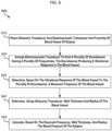
- FIG. 6 is an operational flow diagram illustrating an example method 600 for measuring blood pressure of a subject, in accordance with some embodiments of the disclosure.
- method 600 may be implemented using a continuous blood pressure measurement device 300 as described above.
- an ultrasound transducer and electroacoustic transducer are brought into proximity of a blood vessel of the subject.
- a continuous blood pressure measurement device 300 including an electroacoustic transducer 310 and ultrasound sensor 320 may be brought into proximity of an artery (e.g., carotid artery or brachial artery) of the patient.
- a substrate 500 including device 300 may be aligned with the subject's artery and subsequently adhered.
- the substrate 500 may be adhered to the patient's arm in proximity to the brachial artery.
- the substrate may be adhered to the patient's neck in proximity to the carotid artery.
- the position of the ultrasound transducer and electroacoustic transducer e.g., device 300 or substrate 500
- the position of the ultrasound transducer and electroacoustic transducer may be adjusted to maximize the amplitude and/or signal-to-noise ratio of measurement signals.
- the electroacoustic transducer is actuated to emit a plurality of soundwaves having a plurality of frequencies.
- audio signal generator 305 may be configured to cause electroacoustic transducer 310 to emit sound waves at a plurality of different frequencies.
- the sound waves may produce a vibrational response in blood vessel (e.g., in a cross section of the blood vessel that the sound waves are directed to).
- the vibrational response may have an amplitude that varies depending on the frequency of the sound waves.
- the frequency of each of the sound waves may be between 1 Hz and 3000 Hz. In some embodiments, the frequency of each of the sound waves may be between 670 Hz and 2300 Hz. In some embodiments, the frequency of each of the soundwaves is about 300 Hz to about 3,000 Hz. In some embodiments, the frequency of each of the soundwaves about 1 Hz to about 3,000 Hz.
- the frequency of each of the soundwaves about 1 Hz to about 300 Hz, about 1 Hz to about 500 Hz, about 1 Hz to about 750 Hz, about 1 Hz to about 1,000 Hz, about 1 Hz to about 1,500 Hz, about 1 Hz to about 2,000 Hz, about 1 Hz to about 2,500 Hz, about 1 Hz to about 3,000 Hz, about 300 Hz to about 500 Hz, about 300 Hz to about 750 Hz, about 300 Hz to about 1,000 Hz, about 300 Hz to about 1,500 Hz, about 300 Hz to about 2,000 Hz, about 300 Hz to about 2,500 Hz, about 300 Hz to about 3,000 Hz, about 500 Hz to about 750 Hz, about 500 Hz to about 1,000 Hz, about 500 Hz to about 1,500 Hz, about 500 Hz to about 2,000 Hz, about 500 Hz to about 2,500 Hz, about 500 Hz to about 3,000 Hz, about 750 Hz to about 1,000 Hz, about Hz to about 1,500 Hz
- the frequency of each of the soundwaves about 1 Hz, about 300 Hz, about 500 Hz, about 750 Hz, about 1,000 Hz, about 1,500 Hz, about 2,000 Hz, about 2,500 Hz, or about 3,000 Hz. In some embodiments, the frequency of each of the soundwaves at least about 1 Hz, about 300 Hz, about 500 Hz, about 750 Hz, about 1,000 Hz, about 1,500 Hz, about 2,000 Hz, or about 2,500 Hz. In some embodiments, the frequency of each of the soundwaves at most about 300 Hz, about 500 Hz, about 750 Hz, about 1,000 Hz, about 1,500 Hz, about 2,000 Hz, about 2,500 Hz, or about 3,000 Hz.
- the frequency of each of the soundwaves is about 1 KHz to about 3,000 KHz. In some embodiments, the frequency of each of the soundwaves is about 1 KHz to about 3,000 KHz. In some embodiments, the frequency of each of the soundwaves is about 1 KHz to about 250 KHz, about 1 KHz to about 750 KHz, about 1 KHz to about 1,000 KHz, about 1 KHz to about 1,250 KHz, about 1 KHz to about 1,500 KHz, about 1 KHz to about 1,750 KHz, about 1 KHz to about 2,000 KHz, about 1 KHz to about 2,250 KHz, about 1 KHz to about 2,500 KHz, about 1 KHz to about 2,750 KHz, about 1 KHz to about 3,000 KHz, about 250 KHz to about 750 KHz, about 250 KHz to about 1,000 KHz, about 250 KHz to about 1,250 KHz, about 250 KHz to about 1,500 KHz, about 250 KHz to about 1,750 KHz, about 250 KHz to about 2,000 KHz, about 250 KHz
- the frequency of each of the soundwaves is about 1 KHz, about 250 KHz, about 750 KHz, about 1,000 KHz, about 1,250 KHz, about 1,500 KHz, about 1,750 KHz, about 2,000 KHz, about 2,250 KHz, about 2,500 KHz, about 2,750 KHz, or about 3,000 KHz. In some embodiments, the frequency of each of the soundwaves is at least about 1 KHz, about 250 KHz, about 750 KHz, about 1,000 KHz, about 1,250 KHz, about 1,500 KHz, about 1,750 KHz, about 2,000 KHz, about 2,250 KHz, about 2,500 KHz, or about 2,750 KHz.
- the frequency of each of the soundwaves is at most about 250 KHz, about 750 KHz, about 1,000 KHz, about 1,250 KHz, about 1,500 KHz, about 1,750 KHz, about 2,000 KHz, about 2,250 KHz, about 2,500 KHz, about 2,750 KHz, or about 3,000 KHz.
- the resonant frequency of vibration of the blood vessel may be determined (e.g., based on the frequency that produced the greatest amplitude of response).
- the resonant frequency may be held for a moment and then recorded in memory (e.g., in computer readable medium 340).
- an ultrasonic sensor is used to detect the resonant frequency by capturing images of the blood vessel (e.g., the cross section) as it vibrates in response to different applied frequencies.
- the frequency that produces the highest amplitude of vibration may be selected (e.g., by a processing device communicatively coupled to the sensor) as the resonant frequency.
- the ultrasonic transducer has a sampling rate of at least 3 kHz.
- the electroacoustic transducer and ultrasonic sensor may be placed adjacent one another and driven in synchronization.
- a small speaker may be placed on either side of the ultrasonic sensor, and the two devices/components may be synchronously driven.
- an optimized search algorithm may be used to adjust the frequency of soundwaves output by the electroacoustic transducer in-between measurements.
- the search algorithm may utilize suitable boundary conditions (e.g., maximum frequency, minimum frequency, rate of frequency adjustment, etc.).
- the search algorithm may begin with a wide frequency scan over a large frequency range that uses large changes of frequency between measurements to find a narrower frequency range within which the resonant peak lies, and then transition to a narrow frequency scan within this narrower frequency range to find the resonant frequency.
- the resonant frequency may be held for a moment and then recorded in memory (e.g., in computer readable medium 340).
- the wall thickness and radius of the blood vessel are determined. These parameters may be determined from the ultrasound images captured using an ultrasound sensor 320. For example, echo-mode ultrasonography may be utilized to determine the wall thickness and radius. Ultrasonic waves may be directed to the blood vessel and ultrasonic waves reflected from echogenic boundaries of the blood vessel may be received. A doppler shift of the reflected ultrasonic waves may be measured using the ultrasonic sensor, and a wave velocity of the blood vessel may be calculated based on this doppler shift. In some embodiments, multiple ultrasonic transducers may be utilized to improve imaging accuracy and/or speed. For example, one transducer could produce an ultrasonic signal while three others listen for echoes, allowing for triangulation of echoes as they are received.
- the blood pressure is calculated based on the resonant frequency, the wall thickness, and the radius.
- the calculated blood pressure may establish a baseline diastolic pressure.
- changes in blood pressure over time e.g., using doppler ultrasound imaging
- a small but persistent inaccuracy aggregate into a large drift over the course of many heartbeats.
- periodic re-baselining may be required to maintain accuracy for a patient under long-term monitoring.
- device 300 or an external display system 350 may display the computed blood pressure over time.
- a processing device 330 of continuous blood pressure measurement device 300 may perform the necessary DSP and calculations to arrive at the patient's blood pressure.
- the electroacoustic transducer may be omitted and the acoustic signals of varying frequencies may be generated by pulsing the ultrasonic sensor at varying frequencies to deliver the energy to the blood vessel.
- This alternative design may have the advantage of using a single sensor to produce both the resonant response and capture ultrasound imaging data.
- the system comprises an ultrasound platform for driving one or more ultrasonic transducers.
- the ultrasound platform processes and/or conditions signals received by one or more ultrasound transducers.
- a continuous blood pressure measurement device 500 may be incorporated into a substrate 510.
- the device 500 may include one or more alignment lines 565 or other markings for aligning one or more sensors or transducers 520, 530, 540, 550 of the device 500 with an artery of a patient prior to taking actuating transducer 310 and taking ultrasound measurements.
- a transparent window 575 is provided for aligning one or more sensors or transducers 520, 530, 540, 550 of the device 500 with an artery of a patient prior to taking actuating transducer 310 and taking ultrasound measurements.
- the device may comprise a transparent window 575 for viewing the artery behind the substrate during placement. A combination of a transparent window and alignment marker may further facilitate placement of the device.
- substrate 510 may include an adhesive that used to hold substrate in place and in alignment with the patient's artery. During application, the adhesive may be exposed by peeling away a paper backing. Adhesives may include a rubber, acrylic, or acrylic blend adhesive.
- the device can be placed on the patient's neck to measure blood pressure through the carotid artery. Similar measurements may be made on the radial or ulnar arteries. By virtue of some embodiments, the measurement of blood pressure may be noninvasive, reliable, fast, and provide continuous measurement, thus considering beat to beat variation. These continuous variations may be presented to a user on a display system 350 as described above.
- the sensors and transducers of the device 500 include at least one ultrasound transducer and at least one electroacoustic transducer. Inclusion of more than one ultrasound transducers may allow for increased resolution as described herein.
- a device comprises two ultrasound transducers and one electroacoustic transducer.
- the patch comprises three ultrasound transducers and one electroacoustic transducer.
- the patch comprises four ultrasound transducers.
- Each transducer 520, 530, 540, 550 may be configured as a transmitter, receiver, or both a transmitter and receiver (transceiver).
- transducer 520 is configured as a transmitter and transducer 540 is configured as a receiver.
- transducer 520 is configured as a transmitter and transducer 530 is configured as a receiver. In some embodiments, transducer 520 is configured as a transmitter and transducer 550 is configured as a receiver. In some embodiments, transducer 530 is configured as a transmitter and transducer 520 is configured as a receiver. In some embodiments, transducer 530 is configured as a transmitter and transducer 540 is configured as a receiver. In some embodiments, transducer 530 is configured as a transmitter and transducer 550 is configured as a receiver. In some embodiments, transducers 520 and 530 are configured as transmitters and transducers 540 and 550 are configured as receivers.
- transducers 530 and 540 are configured as transmitters and transducers 520 and 550 are configured as receivers. In some embodiments, transducers 520 and 550 are configured as transmitters and transducers 530 and 540 are configured as receivers. In some embodiments, transducers 520 and 540 are configured as transmitters and transducers 530 and 550 are configured as receivers. In some embodiments, transducer 520 is configured as transmitters and transducers 530 and 540 are configured as receivers. In some embodiments, transducer 530 is configured as transmitters and transducers 550 and 540 are configured as receivers.
- the one or more transducers is incorporate into a wearable device.
- Wearable devices may include a wristband or watch, wherein the one or more transducers are directed to a brachial artery to determine a mean arterial pressure.
- the substrate comprising the one or more transducers is incorporated into a wearable device.
- the wearable device may communicate wirelessly with an external computing device to display or record data.
- the device comprises four ultrasound transducers and an electroacoustic transducer or speaker.
- images or signals captured by the ultrasound transducers are input into a rotational matrix.
- Rotation and/or skew matrices may be applied to properly orient the received signals for convolution, deconvolution, or normalization. Normalization may be applied to received signals, as disclosed herein.
- a skew parameter is applied to the rotational matrices.
- Each ultrasonic transducer of the plurality of ultrasonic transducers may be configured to transmit a transmitted ultrasonic imaging signal to an object.
- Each ultrasonic transducer of the plurality may be configured to transmit a transmitted ultrasonic imaging signal having a frequency of about 100 kHz, about 200 kHz, about 300 kHz, about 400 kHz, about 500 kHz, about 650 kHz, about 700 kHz, about 800 kHz, about 850 kHz, about 900 kHz, about 1 MHz, about 2 MHz, about 3 MHz, about 5.5 MHz, about 6 MHz, about 8 MHz, about 11 MHz, about 15 MHz, about 20 MHz, about 25 MHz, or about 30 MHz
- Each ultrasonic transducer of the plurality may be configured to transmit a transmitted ultrasonic imaging signal having a frequency that is within a range defined by any two of the preceding values.
- Each ultrasonic transducer of the plurality of ultrasonic transducers may be configured to receive a received ultrasonic imaging signal from an object.
- Each ultrasonic transducer of the plurality may be configured to receive a received ultrasonic imaging signal having a frequency of about 100 kHz, about 200 kHz, about 300 kHz, about 400 kHz, about 500 kHz, about 650 kHz, about 700 kHz, about 800 kHz, about 850 kHz, about 900 kHz, about 1 MHz, about 2 MHz, about 3 MHz, about 5.5 MHz, about 6 MHz, about 8 MHz, about 11 MHz, about 15 MHz, about 20 MHz, about 25 MHz, or about 30 MHz
- Each ultrasonic transducer of the plurality may be configured to receive a received ultrasonic imaging signal having a frequency that is within a range defined by any two of the preceding values.
- Each ultrasonic transducer of the plurality may be configured both to transmit and to receive.
- Each ultrasonic transducer of the plurality may be configured to transmit transmitted ultrasonic imaging signals or receive received ultrasonic imaging signals at a frequency that is the same as one or more of the frequencies transmitted or received by other ultrasonic transducer of the plurality.
- Each ultrasonic transducer of the plurality may be configured to transmit transmitted ultrasonic imaging signals or receive received ultrasonic imaging signals at a frequency that is different from all of frequencies transmitted or received by all other ultrasonic transducer of the plurality.
- Each of the ultrasonic transducer of the plurality may be configured to transmit or receive at the same time as one or more other ultrasonic transducer of the plurality.
- a first transmitted imaging signal of a first ultrasonic transducer of the plurality may have a frequency of about 100 kHz, about 200 kHz, about 300 kHz, about 400 kHz, about 500 kHz, about 650 kHz, about 700 kHz, about 800 kHz, about 850 kHz, about 900 kHz, about 1 MHz, about 2 MHz, about 3 MHz, about 5.5 MHz, about 6 MHz, about 8 MHz, or about 11 MHz
- a second transmitted imaging signal of a second ultrasonic transducer of the plurality may have a frequency that is in a range from about 0.5 MHz to about 30 MHz.
- a first received imaging signal of a first ultrasonic transducer of the plurality may have a frequency of about 100 kHz, about 200 kHz, about 300 kHz, about 400 kHz, about 500 kHz, about 650 kHz, about 700 kHz, about 800 kHz, about 850 kHz, about 900 kHz, about 1 MHz, about 2 MHz, about 3 MHz, about 5.5 MHz, about 6 MHz, about 8 MHz, or about 11 MHz
- a second received imaging signal of a second ultrasonic transducer of the plurality may have a frequency that is in a range from about 0.5 MHz to about 30 MHz.
- a first transmitted imaging signal of a first ultrasonic transducer of the plurality may have a frequency that is in a range from about 0.5 MHz to about 30 MHz
- a second transmitted imaging signal of a second ultrasonic transducer of the plurality may have a frequency that is in a range from about 0.5 MHz to about 30 MHz, but that is different from the frequency of the first transmitted imaging signal.
- a first received imaging signal of a first ultrasonic transducer of the plurality may have a frequency that is in a range from about 0.5 MHz to about 30 MHz
- a second received imaging signal of a second ultrasonic transducer of the plurality may have a frequency that is in a range from about 0.5 MHz to about 30 MHz, but that is different from the frequency of the first received imaging signal.
- a third, fourth, fifth, sixth, seventh, eighth, ninth, tenth, eleventh, twelfth, thirteenth, fourteenth, fifteenth, or sixteenth transmitted imaging signal of a third, fourth, fifth, sixth, seventh, eighth, ninth, tenth, eleventh, twelfth, thirteenth, fourteenth, fifteenth, or sixteenth ultrasonic transducer, respectively, may have a frequency that is about 100 kHz, about 200 kHz, about 300 kHz, about 400 kHz, about 500 kHz, about 650 kHz, about 700 kHz, about 800 kHz, about 850 kHz, about 900 kHz, about 1 MHz, about 2 MHz, about 3 MHz, about 5.5 MHz, about 6 MHz, about 8 MHz, or about 11 MHz.
- the third, fourth, fifth, sixth, seventh, eighth, ninth, tenth, eleventh, twelfth, thirteenth, fourteenth, fifteenth, or sixteenth transmitted imaging signal may have a frequency that is within a range described by any two of the preceding values.
- the third, fourth, fifth, sixth, seventh, eighth, ninth, tenth, eleventh, twelfth, thirteenth, fourteenth, fifteenth, or sixteenth transmitted imaging signal may have a value that is in a range from about 0.5 MHz to about 30 MHz.
- the third, fourth, fifth, sixth, seventh, eighth, ninth, tenth, eleventh, twelfth, thirteenth, fourteenth, fifteenth, or sixteenth transmitted imaging signal may have a frequency that is different from one or more of the frequencies of the first and second transmitted imaging signals.
- a third, fourth, fifth, sixth, seventh, eighth, ninth, tenth, eleventh, twelfth, thirteenth, fourteenth, fifteenth, or sixteenth received imaging signal of a third, fourth, fifth, sixth, seventh, eighth, ninth, tenth, eleventh, twelfth, thirteenth, fourteenth, fifteenth, or sixteenth ultrasonic transducer, respectively, may have a frequency that is about 100 kHz, about 200 kHz, about 300 kHz, about 400 kHz, about 500 kHz, about 650 kHz, about 700 kHz, about 800 kHz, about 850 kHz, about 900 kHz, about 1 MHz, about 2 MHz, about 3 MHz, about 5.5 MHz, about 6 MHz, about 8 MHz, or about 11 MHz.
- the third, fourth, fifth, sixth, seventh, eighth, ninth, tenth, eleventh, twelfth, thirteenth, fourteenth, fifteenth, or sixteenth received imaging signal may have a frequency that is within a range described by any two of the preceding values.
- the third, fourth, fifth, sixth, seventh, eighth, ninth, tenth, eleventh, twelfth, thirteenth, fourteenth, fifteenth, or sixteenth received imaging signal may have a value that is in a range from about 0.5 MHz to about 30 MHz.
- the third, fourth, fifth, sixth, seventh, eighth, ninth, tenth, eleventh, twelfth, thirteenth, fourteenth, fifteenth, or sixteenth received imaging signal may have a frequency that is different from one or more of the frequencies of the first and second transmitted imaging signals.
- Each ultrasonic transducer of the plurality of transducers may transmit transmitted ultrasonic imaging signals or receive received ultrasonic imaging signals within a bandwidth.
- the first ultrasonic transducer may have a first bandwidth and the second ultrasonic transducer may have a second bandwidth.
- the first bandwidth and the second bandwidth may overlap.
- the first bandwidth and the second bandwidth may partially overlap.
- the first bandwidth and the second bandwidth may not overlap.
- the third, fourth, fifth, sixth, seventh, eighth, ninth, tenth, eleventh, twelfth, thirteenth, fourteenth, fifteenth, or sixteenth ultrasonic transducers may have third, fourth, fifth, sixth, seventh, eighth, ninth, tenth, eleventh, twelfth, thirteenth, fourteenth, fifteenth, or sixteenth bandwidths, respectively. Any one of the first, second, third, fourth, fifth, sixth, seventh, eighth, ninth, tenth, eleventh, twelfth, thirteenth, fourteenth, fifteenth, or sixteenth bandwidths may overlap one another.
- any one of the first, second, third, fourth, fifth, sixth, seventh, eighth, ninth, tenth, eleventh, twelfth, thirteenth, fourteenth, fifteenth, or sixteenth bandwidths may partially overlap one another. Any one of the first, second, third, fourth, fifth, sixth, seventh, eighth, ninth, tenth, eleventh, twelfth, thirteenth, fourteenth, fifteenth, or sixteenth bandwidths may not overlap one another.
- the received imaging signals may be subjected to pre-processing operations. For instance, a first received imaging signal may form a basis for normalizing other received imaging signals. A second received imaging signal may be normalized by the first received imaging signal. A third, fourth, fifth, sixth, seventh, eighth, ninth, tenth, eleventh, twelfth, thirteenth, fourteenth, fifteenth, or sixteenth received imaging signal may be normalized by the first received imaging signal.
- the system may comprise a transmit (Tx) generator.
- the transmit generator may comprise a host computer, software-defined radio, and ultrasound signal processing circuit (USPC), as disclosed herein.
- the Tx generator may be a Tx beamformer.
- the Tx generator may be configured to operate any one of the ultrasonic transducers to transmit a first, second, third, or fourth transmitted ultrasonic imaging signal, respectively.
- the Tx generator may operate any two or more of the first, second, third, or fourth ultrasonic imaging transducers simultaneously.
- the system may further comprise an image synthesis module.
- the image synthesis module may comprise a receive (Rx) beamformer.
- the Rx beamformer may be configured to operate any one of ultrasonic transducers to receive a first, second, third, or fourth received ultrasonic imaging signal, respectively.
- the image synthesis module may subject the received ultrasonic imaging signals to an ultrasonic image reconstruction operation. For instance, the image synthesis module may subject the received ultrasonic imaging signals to a delay and sum operation. The image synthesis module may subject the received ultrasonic imaging signals to any ultrasonic image reconstruction operation.
- the Tx generator may be configured to operate fifth, sixth, seventh, eighth, ninth, tenth, eleventh, twelfth, thirteenth, fourteenth, fifteenth, or sixteenth ultrasonic transducers to transmit fifth, sixth, seventh, eighth, ninth, tenth, eleventh, twelfth, thirteenth, fourteenth, fifteenth, or sixteenth transmitted ultrasonic imaging signals, respectively.
- the Tx generator may operate any two or more of the first, second, third, fourth, fifth, sixth, seventh, eighth, ninth, tenth, eleventh, twelfth, thirteenth, fourteenth, fifteenth, or sixteenth ultrasonic imaging transducers simultaneously.
- the Rx beamformer may be configured to operate fifth, sixth, seventh, eighth, ninth, tenth, eleventh, twelfth, thirteenth, fourteenth, fifteenth, or sixteenth ultrasonic transducers to transmit fifth, sixth, seventh, eighth, ninth, tenth, eleventh, twelfth, thirteenth, fourteenth, fifteenth, or sixteenth transmitted ultrasonic imaging signals, respectively.
- the Tx generator may be configured to operate any one of the first, second, third, fourth, fifth, sixth, seventh, eighth, ninth, tenth, eleventh, twelfth, thirteenth, fourteenth, fifteenth, or sixteenth ultrasonic transducers to transmit in sequence.
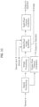
- FIG. 11 schematically illustrates a method of forming ultrasonic images from a plurality of ultrasonic transducers.
- the method may utilize measurements from a plurality of ultrasonic imaging sensors.
- the method may utilize single-pixel and multi-pixel image processing techniques.
- an n-th ultrasonic imaging measurement (where n is a positive integer) may be input to a signal processing unit.
- the signal processing unit may apply any ultrasonic signal processing procedure to the n-th ultrasonic imaging measurement.
- the signal processing unit may output a signal processed measurement to an image processing unit and to a single-pixel feature extraction unit.
- the image processing unit may apply any ultrasonic image processing procedure.
- the single-pixel feature extraction unit may apply any ultrasonic single-pixel feature extraction procedure.
- the single-pixel feature extraction unit may output an extracted feature to an operator.
- an m-th and an (m+1)-th (where m and m+1 are positive integers) ultrasonic imaging measurement may be input to a multi-pixel image synthesis unit and to a multi-pixel feature extraction unit.
- the image synthesis unit may apply any ultrasonic image synthesis procedure.
- the multi-pixel feature extraction unit may apply any ultrasonic multi-pixel feature extraction procedure.
- the multi-feature extraction unit may output an extracted feature to an operator. Multi-pixel extraction may be utilized to build 3D pixels (i.e. voxels).
- image processing methods such as 2-dimensional smoothing filters, Harr filters, Gaussian filters, and integrators may be used to improve the recorded image. Furthermore, each pixel may be filtered in the time-domain to accentuate signal features.
- a single or multiple Butterworth, Chebyshev, and elliptic filters can be used to suppress noise and enhance feature extraction.
- Sensors of the device may further comprise a temperature sensor, an optical sensor, an electrical sensor, a chemical sensor and an electrochemical sensor.
- additional sensors allow measurement of body temperature, a respiration rate, a blood pressure level, and a blood oxygenation saturation (spO 2 ) level.
- the stethoscope device may comprise a first ultrasonic transducer, a light source, and a light detector.
- the stethoscope device may optionally comprise a second ultrasonic transducer.
- the first ultrasonic transducer may operate in a Tx mode.
- the second ultrasonic transducer may operate in a receive mode.
- the stethoscope device may be placed above the skin of a subject (such as skin in a subject's arm). As a bolus of blood travels through an artery beneath the skin of the subject, the stethoscope device may transmit an ultrasonic signal from the first ultrasonic transducer and an optical signal from the light source. The ultrasonic signal or the optical signal may be scattered, dispersed, or reflected from the bolus.
- the scattered, dispersed, or reflected ultrasonic signal or optical signal may be detector by the second ultrasonic transducer or the light detector, respectively.
- the intensity of the scattered, dispersed, or reflected ultrasonic signal or optical signal may be compared to the intensity of the transmitted ultrasonic signal or the transmitted optical signal, respectively.
- These measurements may yield a velocity of the blood bolus as measured by the ultrasonic imaging signal and the optical signal, respectively.
- the velocity of the blood bolus as measured by the ultrasonic imaging signal may be normalized by the velocity of the blood bolus as measured by the optical signal, or vice versa.
- These values may be synthesized and correlated to determine one or more physiological parameters of the subject, such as the subject's heart rate, blood pressure, or respiration.
- Ultrasonic tissue imaging may be plagued by poor optical and acoustic transmissivity as well as beam scattering.
- a method of multi-wavelength ultrasound imaging by collection of information from a plurality of ultrasound sensors, where each sensor has an ultrasound transducer with a unique resonance frequency may be utilized.
- ultrasound emitted by the plurality of transducers may simultaneously penetrate various depths in a given cross-sectional area of physiology (e.g., tissue).
- ultrasound sensors having acoustic frequency responses may be actuated in a time interleaved fashion such that each sensor may be used to image a physiological surface at a unique depth.
- each sensor may be simultaneously actuated with a combination of other sensors to generate higher order harmonics which allow for sub-pixel feature resolution (i.e., super resolution imaging).
- the term “resonant frequency” generally refers to an operating frequency at which the transducer most efficiently converts electrical energy into mechanical energy.
- the term resonant frequency may refer to an operating frequency at which the piezoelectrical material most readily vibrates and converts electrical energy into mechanical energy most efficiently.
- each ultrasound sensor may have a transducer configured with a unique resonance frequency. Specifically, the ultrasound transducers may be selected such that their acoustic frequency responses are non-overlapping. By actuating the transducers in a time interleaved fashion, each sensor may be used to image a surface of a sample at a unique depth. Furthermore, each transducer may be simultaneously actuated with a combination of other transducers to generate higher order harmonics that allow for sub-pixel feature resolution.
- selecting transducers 711, 712, 713 having frequencies which are partially overlapping may allow for self-normalization and cross-correlation of signals.
- the measurement of any pair of sensors may be normalized, thereby reducing systemic sources of noise and significantly increasing signal integrity.
- the simultaneous interrogation of a surface with transducers with distinct resonance frequencies can be used to generate super-resolution ultrasound images of an object 700.
- the frequency overlap between sensors 711, 712, 713 may be configured to be about 200 KHz or less.
- the frequency overlap between sensors may be configured such that a frequency response range of one sensor does not overlap with a resonant frequency of another sensor.
- a first sensor 711 having a resonant frequency 721 and a second sensor 712 having a resonant frequency 722 partially overlap in frequency response.
- a second sensor 712 and a third sensor 713 having a resonant frequency 723 partially overlap in frequency response.
- the frequency overlap between sensors is about 10 KHz to about 500 KHz. In some embodiments, the frequency overlap between sensors is about 10 KHz to about 20 KHz, about 10 KHz to about 30 KHz, about 10 KHz to about 40 KHz, about 10 KHz to about 50 KHz, about 10 KHz to about 75 KHz, about 10 KHz to about 100 KHz, about 10 KHz to about 150 KHz, about 10 KHz to about 200 KHz, about 10 KHz to about 300 KHz, about 10 KHz to about 400 KHz, about 10 KHz to about 500 KHz, about 20 KHz to about 30 KHz, about 20 KHz to about 40 KHz, about 20 KHz to about 50 KHz, about 20 KHz to about 75 KHz, about 20 KHz to about 100 KHz, about 20 KHz to about 150 KHz, about 20 KHz to about 200 KHz, about 20 KHz to about 300 KHz, about 20 KHz to about 400 KHz, about 20 KHz to about 500 KHz, about 30 KHz to about 40 KHz, about 30 KHz, about 10
- the frequency overlap between sensors is about 10 KHz, about 20 KHz, about 30 KHz, about 40 KHz, about 50 KHz, about 75 KHz, about 100 KHz, about 150 KHz, about 200 KHz, about 300 KHz, about 400 KHz, or about 500 KHz. In some embodiments, the frequency overlap between sensors is at least about 10 KHz, about 20 KHz, about 30 KHz, about 40 KHz, about 50 KHz, about 75 KHz, about 100 KHz, about 150 KHz, about 200 KHz, about 300 KHz, or about 400 KHz.
- the frequency overlap between sensors is at most about 20 KHz, about 30 KHz, about 40 KHz, about 50 KHz, about 75 KHz, about 100 KHz, about 150 KHz, about 200 KHz, about 300 KHz, about 400 KHz, or about 500 KHz.
- FIGS. 8A-8D depicts a technique for cross-correlation in an ultrasound measurement device.
- the cross-correlation of signals from any pair of sensors 811, 812, 813 whose frequency responses overlap allows for a redundant measurement of a voxel.
- the transducers of the sensors may be actuated in a time-interleaved fashion.
- the received echo may be measured by all three transducers 811, 812, 812 as depicted in FIG. 8B to obtain received signals 821, 822, 823 on all three transducers as depicted in FIG. 8C .
- FIG. 8C illustrates the event where the echo from actuation of a second sensor 812 is measured by all three sensors.
- the frequency response of a first sensor 811 and a second sensor 812 is convolved in the frequency domain with the received echo waveform.
- the measurement from the third sensor may be correlated with the measurement from the second sensor while using the measurement of first sensor to normalize the measurement of the second sensor.
- FIG. 8D a much sharper peak in a signal monitored by the second sensor is obtained, and those sharper peaks may be achieved by the aforementioned cross-frequency normalization.
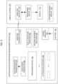
- FIG. 9 depicts an ultrasound signal processing circuit (USPC) 950 configured to process and/or condition ultrasound signals transmitted between one or more ultrasound transducers 930 and a software-defined radio system 920, according to some embodiments.
- the system used to generate and receive ultrasound signals may be correspond to a transmit (Tx) generator and/or a receive (Rx) beamformer as described herein.
- Tx transmit
- Rx receive
- One or more signals transmitted by the software-defined radio system may be referred to as the outputs of the software-defined radio system.
- One or more signals transmitted by the software-defined radio system may be referred to as the inputs of the software-defined radio system.
- the software-defined radio system 920 transmits one or more signals 922, 924 to the ultrasound signal processing circuit (USPC) 950.
- a first transmission signal 922 comprises a transmission pulse or reference clock.
- a second transmission 924 signal comprises a gain ramp.
- the transmission pulse 922 is a low-voltage transmission pulse.
- the transmission pulse 922 is a +/- 4 volt signal.
- a first transmission signal 922 is received by a high-voltage amplifier 952.
- a transmission pulse or reference clock is input into the high-voltage amplifier 952.
- an amplified signal from the high-voltage amplifier 952 passes through a diode 954.
- the first transmission signal 922 is then transmitted to a first multiplexer 982.
- the first transmission signal 922 is a transmission pulse or reference clock transmitted to the first multiplexer 982.
- diode 954 is an anti-parallel diode configured to block received signals from the ultrasound transducer 930 or multiplexer 982 to the high-voltage amplifier 952.
- a high-voltage amplifier may be a discrete amplifier.
- the high voltage amplifier output signal is a +/- 100 volt amplifier.
- the high voltage amplifier 952 creates a +/- 100 volt device signal from a low voltage output of the software-defined radio 920.
- an output from the first multiplexer 928 is transmitted to the one or more ultrasound transducers 930.
- the output from the first multiplexer 928 is received by a first pixel group of the ultrasound transducers 930.
- the ultrasound transducers 930 may then transmit a first pixel group ultrasonic signal to an object.
- the object may then reflect the transmitted ultrasonic signal and the ultrasound transducers 930 may receive the reflected signal.
- the reflected signal is received as part of a first pixel group.
- the reflected signal is received as part of a second pixel group.
- the reflected signal forms both a first pixel group and a second pixel group.
- the ultrasound transducers 930 may then transmit the received reflected signal as an electrical signal.
- the received reflected signal from a first pixel group may be considered a first received signal.
- the first received signal may be received from the transducers 930 by the first multiplexer 982.
- the received reflected signal from a second pixel group may be considered a second received signal.
- the second received signal may be received from the transducers 930 by the second multiplexer 984.
- signals are wirelessly transmitted between the multiplexers 982, 984 and the one or more ultrasound transducers 930.
- a wireless communication link between the multiplexers 982,984 and ultrasound transducers 930 may be a wireless mode such as a Bluetooth ® or Bluetooth ® low energy (LE) link, a Wi-Fi ® link, a ZigBee link, or some other suitable wireless communication link.
- a wired communication link between the multiplexers 982,984 and ultrasound transducers 930 may be achieved using a wired transmitter or other suitable wired interface.
- data may be transferred using a USB-C connector, a USB 2.x or 3.x connector, a micro-USB connector, a THUNDERBOLT connector, an Ethernet cable, etc.
- One or more signals transmitted to the ultrasound transducers may be referred to as the inputs of the ultrasound transducers.
- One or more signals transmitted by the ultrasound transducers may be referred to as the outputs of ultrasound transducers.
- the outputs of the ultrasound transducers may correspond to the reflected ultrasound signals measured or detected by the ultrasound transducers.
- the first multiplexer 982 transmits the first received signal from the first pixel group to a first low-noise amplifier 964.
- the first received signal passes through a high-voltage blocker 966.
- the high voltage blocker 966 may prevent signals from the high-voltage amplifier 952 from passing to the first low-noise amplifier.
- the blocker 966 may be a high voltage protection transmit/ receive switch (T/R switch), such as a MD0100.
- the first low-noise amplifier 964 is a low noise, single-ended, linear in dB, general purpose variable gain amplifier, such as an AD8336.
- the first received signal is then received by a first variable gain amp 962.
- the first low-noise amplifier 964, the first variable gain amplifier 962, the second low-noise amplifier 974, and the second variable gain amplifier 972 utilize the same chip type.
- amplifiers 962, 964, 972, 974 receive faint return pulses an amplify them according to a gain ramp signal.
- 962, 964, 972, 974 receive faint return pulses an amplify them according to a second transmission signal 924 which is gain ramp signal.
- the amplification of the ramp signal corresponds to the time since the input pulse.
- the rate or ration of amplification is determined by the time since the initial pulse of the gain ramp signal was emitted.
- the return pulses are the received signals.
- a second transmission 924 signal is transmitted to a first variable gain amplifier 962.
- the signal output by the first variable gain amplifier 962 is received by the first receive channel 926 of the software-defined radio system 920 and the second variable gain amplifier 972.
- a signal output by the second variable gain amplifier 972 is received by the second receive channel 928 of the software-defined radio system 920.
- the first multiplexer 982 is a 16-channel multiplexer. In some embodiments, the second multiplexer 984 is a 16-channel multiplexer. In some embodiments, the first pixel group comprises a 16 pixels. In some embodiments, the second pixel group comprises a 16 pixels. In some embodiments, the first pixel group functions as a transmit and receive (transceiver) group. In some embodiments, the second pixel group functions as a receive only group. In some embodiments, the resolution of the system is 14 bits. In some embodiments, the resolution of the system is 16 bits. In some embodiments, the system is module and additional hardware may be utilized to increase the channel number. In some embodiments, the system may comprise 16 channels to 2,048 channels.
- the system may comprise 16 channels to 32 channels, 16 channels to 64 channels, 16 channels to 128 channels, 16 channels to 256 channels, 16 channels to 512 channels, 16 channels to 1,024 channels, 16 channels to 2,048 channels, 32 channels to 64 channels, 32 channels to 128 channels, 32 channels to 256 channels, 32 channels to 512 channels, 32 channels to 1,024 channels, 32 channels to 2,048 channels, 64 channels to 128 channels, 64 channels to 256 channels, 64 channels to 512 channels, 64 channels to 1,024 channels, 64 channels to 2,048 channels, 128 channels to 256 channels, 128 channels to 512 channels, 128 channels to 1,024 channels, 128 channels to 2,048 channels, 256 channels to 512 channels, 256 channels to 1,024 channels, 256 channels to 2,048 channels, 512 channels to 1,024 channels, 512 channels to 2,048 channels, or 1,024 channels to 2,048 channels.
- the system may comprise 16 channels, 32 channels, 64 channels, 128 channels, 256 channels, 512 channels, 1,024 channels, or 2,048 channels. In some embodiments, the system may comprise at least 16 channels, 32 channels, 64 channels, 128 channels, 256 channels, 512 channels, or 1,024 channels. In some embodiments, the system may comprise at most 32 channels, 64 channels, 128 channels, 256 channels, 512 channels, 1,024 channels, or 2,048 channels.
- the software-defined radio system 920 is a Universal Software Radio Peripheral (USRP), such as a National Instruments USRP N210.
- the software-defined radio system 920 connects to a host computer 910.
- the radio system 920 connects to the computer 910 through a high-speed link.
- the high-speed link comprises an ethernet connection.
- the ethernet connection is a gigabit ethernet connection which may allow for sampling rates up 50 MS/s (Mega Samples per second).
- a host-based software is loaded onto the computer 910 and utilized to control the radio system hardware and transmit/receive data.
- the general functionality of a host computer is implemented into the radio system 920 with an embedded processor that allows the radio system 920 to operate in a stand-alone fashion.
- connection to a computer 910 comprises a universal serial bus (USB) connection, a fiber optical connection, a peripheral component interconnect expresses (PCle) connection, or other suitable connection.
- connection to a computer 910 may allow the system to utilize the rapid access memory (RAM) of the computer.
- an embedded processor may comprise a RAM buffer.
- the RAM buffer may comprise 4, 8, 16, 32, 64, 80, 128, or 256 gigabytes (GB).
- the software-defined radio system 920 comprises a motherboard.
- the motherboard may provide the following subsystems: clock generation and synchronization, a field-programmed gate array (FPGA), one or more analog-to-digital converters (ADCs), one or more digital-to-analog converters (DACs), a host processor interface, and a power regulation.
- a modular front-end, or daughterboard is used for analog operations such as up/down-conversion, filtering, and other signal conditioning. This modularity may permit the software-defined radio system 920 to serve applications that operate between DC and 6 GHz.
- the system operates between DC and 5MHz.
- the system operates only down to 1 MHz, which may be considered the limit of a normal ultrasonic signal.
- the system operates at about 1 Hz to 3000 Hz frequencies for production of resonant mode soundwaves.
- signals received by a first receive channel 926 or a second receive channel 928 of the software-defined radio system 920 may be adjusted to provide a received signal gain of about -14 decibels (dB) to +60 dB.
- a transmitter daughterboard module is implemented to modulate an output signal to a higher frequency.
- a receiver daughterboard module is implemented to acquire an RF signal and converts it to baseband.
- a transceiver daughterboard module is implemented to combine the functionality of a transmitter and receiver.
- the FPGA of the software-defined radio system 920 performs several digital signal processing (DSP) operations.
- DSP digital signal processing
- the DSP operation performed by the FPGA provide translation from real signals in the analog domain to lower-rate, complex, baseband signals in the digital domain.
- these complex samples are transferred to/from applications running on a host processor, which perform DSP operations.
- the hardware driver of the software-defined radio system 920 supports an operating system, such as Linux, MacOS, and Windows platforms. In some embodiments several frameworks, including GNU Radio, LabVIEW, MATLAB and Simulink may use the hardware driver.
- the functionality provided by hardware driver may also be accessed directly with a hardware driver application programming interface (API).
- the API provides native support for C++ or any other language that can import C++ functions.
- FIG. 10 shows a computer system 1001 that is programmed or otherwise configured to, for example, implement the methods disclosed herein.
- the computer system 1001 can be an electronic device of a user or a computer system that is remotely located with respect to the electronic device.
- the electronic device can be a mobile electronic device.
- the computer system 1001 includes a central processing unit (CPU, also "processor” and “computer processor” herein) 1005, which can be a single core or multi core processor, or a plurality of processors for parallel processing.
- the computer system 1001 also includes memory or memory location 1010 (e.g., random-access memory, read-only memory, flash memory), electronic storage unit 1015 (e.g., hard disk), communication interface 1020 (e.g., network adapter) for communicating with one or more other systems, and peripheral devices 1025, such as cache, other memory, data storage and/or electronic display adapters.
- the memory 1010, storage unit 1015, interface 1020 and peripheral devices 1025 are in communication with the CPU 1005 through a communication bus (solid lines), such as a motherboard.
- the storage unit 1015 can be a data storage unit (or data repository) for storing data.
- the computer system 1001 can be operatively coupled to a computer network ("network") 1030 with the aid of the communication interface 1020.
- the network 1030 can be the Internet, an internet and/or extranet, or an intranet and/or extranet that is in communication with the Internet.
- the network 1030 in some cases is a telecommunication and/or data network.
- the network 1030 can include one or more computer servers, which can enable distributed computing, such as cloud computing.
- the network 1030, in some cases with the aid of the computer system 1001, can implement a peer-to-peer network, which may enable devices coupled to the computer system 1001 to behave as a client or a server.
- the CPU 1005 can execute a sequence of machine-readable instructions, which can be embodied in a program or software.
- the instructions may be stored in a memory location, such as the memory 1010.
- the instructions can be directed to the CPU 1005, which can subsequently program or otherwise configure the CPU 1005 to implement methods of the present disclosure. Examples of operations performed by the CPU 1005 can include fetch, decode, execute, and writeback.
- the CPU 1005 can be part of a circuit, such as an integrated circuit.
- a circuit such as an integrated circuit.
- One or more other components of the system 1001 can be included in the circuit.
- the circuit is an application specific integrated circuit (ASIC).
- the storage unit 1015 can store files, such as drivers, libraries, and saved programs.
- the storage unit 1015 can store user data, e.g., user preferences and user programs.
- the computer system 1001 in some cases can include one or more additional data storage units that are external to the computer system 1001, such as located on a remote server that is in communication with the computer system 1001 through an intranet or the Internet.
- the computer system 1001 can communicate with one or more remote computer systems through the network 1030.
- the computer system 1001 can communicate with a remote computer system of a user (e.g., a smartphone, a laptop computer).
- remote computer systems include personal computers (e.g., portable PC), slate or tablet PC's (e.g., Apple ® iPad, Samsung ® Galaxy Tab), telephones, Smart phones (e.g., Apple ® iPhone, Android-enabled device, Blackberry ® ), or personal digital assistants.
- the user can access the computer system 1001 via the network 1030.
- Methods as described herein can be implemented by way of machine (e.g., computer processor) executable code stored on an electronic storage location of the computer system 1001, such as, for example, on the memory 1010 or electronic storage unit 1015.
- the machine executable or machine-readable code can be provided in the form of software.
- the code can be executed by the processor 1005.
- the code can be retrieved from the storage unit 1015 and stored on the memory 1010 for ready access by the processor 1005.
- the electronic storage unit 1015 can be precluded, and machine-executable instructions are stored on memory 1010.
- the code can be pre-compiled and configured for use with a machine having a processer adapted to execute the code or can be compiled during runtime.
- the code can be supplied in a programming language that can be selected to enable the code to execute in a pre-compiled or as-compiled fashion.
- aspects of the systems and methods provided herein can be embodied in programming.
- Various aspects of the technology may be thought of as “products” or “articles of manufacture” typically in the form of machine (or processor) executable code and/or associated data that is carried on or embodied in a type of machine readable medium.
- Machine-executable code can be stored on an electronic storage unit, such as memory (e.g., read-only memory, random-access memory, flash memory) or a hard disk.
- “Storage” type media can include any or all of the tangible memory of the computers, processors or the like, or associated modules thereof, such as various semiconductor memories, tape drives, disk drives and the like, which may provide non-transitory storage at any time for the software programming.
- All or portions of the software may at times be communicated through the Internet or various other telecommunication networks. Such communications, for example, may enable loading of the software from one computer or processor into another, for example, from a management server or host computer into the computer platform of an application server.
- another type of media that may bear the software elements includes optical, electrical, and electromagnetic waves, such as used across physical interfaces between local devices, through wired and optical landline networks and over various air-links.
- the physical elements that carry such waves, such as wired or wireless links, optical links, or the like, also may be considered as media bearing the software.
- terms such as computer or machine "readable medium” refer to any medium that participates in providing instructions to a processor for execution.
- a machine readable medium such as computer-executable code
- a tangible storage medium such as computer-executable code
- Non-volatile storage media include, for example, optical or magnetic disks, such as any of the storage devices in any computer(s) or the like, such as may be used to implement the databases, etc. shown in the drawings.
- Volatile storage media include dynamic memory, such as main memory of such a computer platform.
- Tangible transmission media include coaxial cables; copper wire and fiber optics, including the wires that comprise a bus within a computer system.
- Carrier-wave transmission media may take the form of electric or electromagnetic signals, or acoustic or light waves such as those generated during radio frequency (RF) and infrared (IR) data communications.
- RF radio frequency
- IR infrared
- Common forms of computer-readable media therefore include for example: a floppy disk, a flexible disk, hard disk, magnetic tape, any other magnetic medium, a CD-ROM, DVD or DVD-ROM, any other optical medium, punch cards paper tape, any other physical storage medium with patterns of holes, a RAM, a ROM, a PROM and EPROM, a FLASH-EPROM, any other memory chip or cartridge, a carrier wave transporting data or instructions, cables or links transporting such a carrier wave, or any other medium from which a computer may read programming code and/or data.
- Many of these forms of computer readable media may be involved in carrying one or more sequences of one or more instructions to a processor for execution.
- the computer system 1001 can include or be in communication with an electronic display 1035 that comprises a user interface (UI) 1040.
- UI user interface
- Examples of UI's include, without limitation, a graphical user interface (GUI), a mobile device application, and web-based user interface.
- FIG. 11 illustrates a chip set 1300, according to some embodiments.
- Chip set 1300 can include, for instance, processor and memory components incorporated in one or more physical packages.
- a physical package includes an arrangement of one or more materials, components, and/or wires on a structural assembly (e.g., a baseboard) to provide one or more characteristics such as physical strength, conservation of size, and/or limitation of electrical interaction.
- chip set 1300 includes a communication mechanism such as a bus 1302 for passing information among the components of the chip set 1300.
- a processor 1304 has connectivity to bus 1302 to execute instructions and process information stored in a memory 1306.
- Processor 1304 includes one or more processing cores with each core configured to perform independently.
- a multi-core processor enables multiprocessing within a single physical package. Examples of a multi-core processor include two, four, eight, or greater numbers of processing cores.
- processor 1304 includes one or more microprocessors configured in tandem via bus 1302 to enable independent execution of instructions, pipelining, and multithreading.
- Processor 1304 may also be accompanied with one or more specialized components to perform certain processing functions and tasks such as one or more digital signal processors (DSP) 1308, and/or one or more application-specific integrated circuits (ASIC) 1310.
- DSP 1308 can typically be configured to process real-world signals (e.g., sound) in real time independently of processor 1304.
- ASIC 1310 can be configured to performed specialized functions not easily performed by a general purposed processor.
- Other specialized components to aid in performing the inventive functions described herein include one or more field programmable gate arrays (FPGA) (not shown), one or more controllers (not shown), or one or more other special-purpose computer chips.
- FPGA field programmable gate arrays
- Memory 1306 includes both dynamic memory (e.g., RAM) and static memory (e.g., ROM) for storing executable instructions that, when executed by processor 1304, DSP 1308, and/or ASIC 1310, perform the process of example embodiments as described herein. Memory 1306 also stores the data associated with or generated by the execution of the process.
- dynamic memory e.g., RAM
- static memory e.g., ROM
- machine readable medium In this document, the terms “machine readable medium,” “computer readable medium,” and similar terms are used to generally refer to non-transitory mediums, volatile or non-volatile, that store data and/or instructions that cause a machine to operate in a specific fashion. Common forms of machine readable media include, for example, a hard disk, solid state drive, magnetic tape, or any other magnetic data storage medium, an optical disc or any other optical data storage medium, any physical medium with patterns of holes, a RAM, a PROM, EPROM, a FLASH-EPROM, NVRAM, any other memory chip or cartridge, and networked versions of the same.
- Instructions may be grouped in the form of computer programs or other groupings. When executed, such instructions may enable a processing device to perform features or functions of the present application as discussed herein.
- a "processing device” may be implemented as a single processor that performs processing operations or a combination of specialized and/or general-purpose processors that perform processing operations.
- a processing device may include a CPU, GPU, APU, DSP, FPGA, ASIC, SOC, and/or other processing circuitry.
- the devices and methods described herein may be utilized for applications in fields outside of the medical fields described above.
- the devices and methods may be used to provide information about the internal conditions of mechanical systems, such as the engines or transmissions of vehicles.
- the stethoscope functionality may be used to detect abnormalities in the mechanical processes of an engine or transmission.
- the ultrasonic functionality may be used to image the engine or transmission to determine if it has sustained internal damage.
- the non-stethoscopic, non-ultrasonic sensors may provide additional information about the state of the engine or transmission, such as its temperature.
- the devices and methods may be used for non-destructive testing of infrastructure. For instance, the devices and methods may be used to examine the internal structure of concrete (in streets or highways, bridges, buildings, or other structures) to determine whether the concrete or metal rebar within the concrete has been damaged. The devices and methods may be used to examine the internal structures of pipelines to determine whether they are damaged and may represent a threat to life, property, or the environment.
- concrete in streets or highways, bridges, buildings, or other structures
- the devices and methods may be used to examine the internal structures of pipelines to determine whether they are damaged and may represent a threat to life, property, or the environment.
- the devices and methods described herein may be utilized to examine the internal structures of other building materials, such as stone, brick, wood, sheetrock, thermal insulating, plastic piping, polyvinyl chloride (PVC) piping, fiberglass, or paint.
- other building materials such as stone, brick, wood, sheetrock, thermal insulating, plastic piping, polyvinyl chloride (PVC) piping, fiberglass, or paint.
- PVC polyvinyl chloride
- range format is merely for convenience and brevity and should not be construed as an inflexible limitation on the scope of the disclosure. Accordingly, the description of a range should be considered to have specifically disclosed all the possible subranges as well as individual numerical values within that range. For example, description of a range such as from 1 to 6 should be considered to have specifically disclosed subranges such as from 1 to 3, from 1 to 4, from 1 to 5, from 2 to 4, from 2 to 6, from 3 to 6 etc., as well as individual numbers within that range, for example, 1, 2, 3, 4, 5, and 6. This applies regardless of the breadth of the range.
- a sample includes a plurality of samples, including mixtures thereof.
- determining means determining if an element is present or not (for example, detection). These terms can include quantitative, qualitative or quantitative and qualitative determinations. Assessing can be relative or absolute. "Detecting the presence of can include determining the amount of something present in addition to determining whether it is present or absent depending on the context.
- a “subject” can be a biological entity containing expressed genetic materials.
- the biological entity can be a plant, animal, or microorganism, including, for example, bacteria, viruses, fungi, and protozoa.
- the subject can be tissues, cells and their progeny of a biological entity obtained in vivo or cultured in vitro.
- the subject can be a mammal.
- the mammal can be a human.
- the subject may be diagnosed or suspected of being at high risk for a disease. In some cases, the subject is not necessarily diagnosed or suspected of being at high risk for the disease.
- in vivo is used to describe an event that takes place in a subject's body.
- ex vivo is used to describe an event that takes place outside of a subject's body.
- An ex vivo assay is not performed on a subject. Rather, it is performed upon a sample separate from a subject.
- An example of an ex vivo assay performed on a sample is an "in vitro" assay.
- in vitro is used to describe an event that takes places contained in a container for holding laboratory reagent such that it is separated from the biological source from which the material is obtained.
- in vitro assays can encompass cell-based assays in which living or dead cells are employed.
- In vitro assays can also encompass a cell-free assay in which no intact cells are employed.
- a number refers to that number plus or minus 10% of that number.
- the term “about” a range refers to that range minus 10% of its lowest value and plus 10% of its greatest value.
- a patient's arm is laid out on a comfortable surface.
- a trained nurse or doctor then places a properly sized cuff around the upper arm of the patient.
- a stethoscope is placed on the brachial artery of the patient just below the cuff
- the trained person then inflates the cuff to 180 mmHG and begins releasing air from the cuff at a suggest rate of 3mm/sec.
- the trained person must simultaneously observe they sphygmomanometer of the cuff while listening with the stethoscope.
- a first "knocking sound” indicates the point at which the systolic pressure of the patient is to be measured using the sphygmomanometer.
- the "knocking sound” disappears, the diastolic pressure of the patient is to be measured using the sphygmomanometer.
- the measured systolic and diastolic pressures should be recorded.
- the subject's blood pressure appears to be elevated, it is recommended that the patient's blood pressure be measured at least two additional times. With a rest period in given in between measurements.
- An adhesive substrate comprising one or more ultrasound transducers and an electroacoustic transducer is adhered proximal to the patient's carotid artery.
- An electroacoustic transducer provided on the adhesive substrate is activated.
- the electroacoustic transducer is varied through a range of audio frequencies.
- the ultrasound transducer detects when resonance in the artery is at a maximum level.
- the resonance frequency is held for a moment and recorded.
- the ultrasound transducer determines the arterial wall thickness and diameter of the artery. The blood pressure of the patient is then calculated and recorded.
Landscapes
- Health & Medical Sciences (AREA)
- Life Sciences & Earth Sciences (AREA)
- Engineering & Computer Science (AREA)
- Physics & Mathematics (AREA)
- General Health & Medical Sciences (AREA)
- Surgery (AREA)
- Pathology (AREA)
- Biomedical Technology (AREA)
- Heart & Thoracic Surgery (AREA)
- Medical Informatics (AREA)
- Molecular Biology (AREA)
- Animal Behavior & Ethology (AREA)
- Biophysics (AREA)
- Public Health (AREA)
- Veterinary Medicine (AREA)
- Radiology & Medical Imaging (AREA)
- Nuclear Medicine, Radiotherapy & Molecular Imaging (AREA)
- Hematology (AREA)
- Gynecology & Obstetrics (AREA)
- Computer Vision & Pattern Recognition (AREA)
- Physiology (AREA)
- General Physics & Mathematics (AREA)
- Computer Networks & Wireless Communication (AREA)
- Acoustics & Sound (AREA)
- Vascular Medicine (AREA)
- Signal Processing (AREA)
- Cardiology (AREA)
- Radar, Positioning & Navigation (AREA)
- Remote Sensing (AREA)
- Otolaryngology (AREA)
- Geometry (AREA)
- Theoretical Computer Science (AREA)
- Multimedia (AREA)
- Mechanical Engineering (AREA)
- Ophthalmology & Optometry (AREA)
- Ultra Sonic Daignosis Equipment (AREA)
- Measuring Pulse, Heart Rate, Blood Pressure Or Blood Flow (AREA)
- Measurement Of The Respiration, Hearing Ability, Form, And Blood Characteristics Of Living Organisms (AREA)
Claims (14)
- Dispositif de mesure de la pression sanguine (300), comprenant :un premier transducteur (250, 310) configuré pour émettre de multiples ondes sonores (240) présentant de multiples fréquences, les ondes sonores étant configurées pour amener un vaisseau sanguin d'un sujet à vibrer ;un deuxième transducteur (320) configuré pour capturer de multiples images ultrasonores du vaisseau sanguin ; etun dispositif de traitement (330) configuré pour :déterminer, sur la base des multiples images ultrasonores capturées, une fréquence de résonance du vaisseau sanguin ; etcalculer, sur la base d'une épaisseur de paroi (110, 210) du vaisseau sanguin, un rayon ou diamètre du vaisseau sanguin et la fréquence de résonance déterminée, une pression sanguine (120) du vaisseau sanguin du sujet,dans lequel la détermination de la fréquence de résonance du vaisseau sanguin comprend :la détermination, à partir des multiples images ultrasonores, sur la base d'une réponse vibratoire du vaisseau sanguin aux ondes sonores, d'une fréquence des multiples fréquences qui optimise une vibration du vaisseau sanguin ; etla sélection de la fréquence comme fréquence de résonance.
- Dispositif de mesure de la pression sanguine selon la revendication 1, comprenant en outre: un générateur de signal audio (305) couplé électriquement au premier transducteur (250, 310), dans lequel le générateur de signal audio (305) est configuré pour amener les multiples ondes sonores à présenter de multiples fréquences.
- Dispositif de mesure de la pression sanguine selon la revendication 1, dans lequel chacune des fréquences est comprise entre 1 Hz et 3 000 Hz ; oudans lequel chacune des fréquences est comprise entre 670 Hz et 2 300 Hz ; oudans lequel le vaisseau sanguin est une artère carotide du sujet ; oudans lequel le transducteur est un haut-parleur audio.
- Dispositif de mesure de la pression sanguine selon la revendication 1, comprenant en outre : un substrat (510), dans lequel le substrat (510) comprend une surface adhésive à faire adhérer à la peau du sujet, dans lequel le premier transducteur (250, 310) et le deuxième transducteur sont incorporés dans le substrat (510).
- Dispositif de mesure de la pression sanguine selon la revendication 4, dans lequel le substrat (510) adhère de manière proximale au vaisseau sanguin ; oudans lequel le substrat adhère de manière proximale à l'artère carotide, oudans lequel le substrat comprend une ligne d'alignement (565), oudans lequel le substrat comprend en outre une fenêtre transparente (575).
- Dispositif de mesure de la pression sanguine selon la revendication 1 ou la revendication 4, comprenant en outre un troisième transducteur configuré pour capturer un deuxième ensemble d'une ou plusieurs images ultrasonores du vaisseau sanguin.
- Dispositif de mesure de la pression sanguine selon la revendication 6, dans lequel le deuxième et le troisième transducteur présentent chacun une fréquence de résonance respective, et dans lequel le deuxième transducteur comprend une réponse de fréquence qui recouvre partiellement une réponse de fréquence du troisième transducteur ; et le dispositif de traitement traite des mesures effectuées par le premier et le deuxième transducteur.
- Dispositif de mesure de la pression sanguine selon la revendication 7, dans lequel le traitement de mesures effectuées par le premier et le deuxième transducteur comprend la normalisation de la première réponse de fréquence et de la seconde réponse de fréquence.
- Dispositif de mesure de la pression sanguine selon la revendication 6 ou la revendication 7, comprenant en outre un quatrième transducteur configuré pour capturer un troisième ensemble d'une ou plusieurs images ultrasonores du vaisseau sanguin.
- Dispositif de mesure de la pression sanguine selon la revendication 9, dans lequel le quatrième transducteur comprend une réponse de fréquence qui recouvre partiellement la réponse de fréquence du deuxième transducteur, ouqui recouvre partiellement la réponse de fréquence du troisième transducteur, ouqui recouvre partiellement la réponse de fréquence du deuxième et du troisième transducteur.
- Support de stockage lisible sur ordinateur non transitoire stockant des instructions exécutables par un processeur (330) d'un dispositif de mesure de la pression sanguine (300), dans lequel l'exécution des instructions amène un dispositif de mesure de la pression sanguine à effectuer des opérations comprenant :l'émission, à l'aide d'un premier transducteur (250, 310) d'un dispositif de mesure de la pression sanguine à proximité d'un vaisseau sanguin d'un sujet, de multiples ondes sonores présentant de multiples fréquences, les ondes sonores amenant un vaisseau sanguin d'un sujet à vibrer ;la capture, à l'aide d'un deuxième transducteur du dispositif de mesure de la pression sanguine, de multiples images ultrasonores du vaisseau sanguin lorsqu'il vibre en réponse aux ondes sonores ;la détermination, à partir des multiples images ultrasonores, sur la base d'une réponse vibratoire du vaisseau sanguin aux multiples ondes sonores, d'une fréquence de résonance du vaisseau sanguin ;la détermination, à l'aide du deuxième transducteur, d'une épaisseur de paroi (110, 210) et d'un rayon ou diamètre du vaisseau sanguin ; etle calcul, sur la base de la fréquence de résonance, de l'épaisseur de paroi (110, 210) du vaisseau sanguin, et du rayon ou diamètre du vaisseau sanguin, d'une pression sanguine (120) du sujet.
- Support de stockage lisible sur ordinateur non transitoire selon la revendication 11, dans lequel la détermination de l'épaisseur de paroi (110, 210) et du rayon du vaisseau sanguin, comprend : la direction, à l'aide du deuxième transducteur, des ondes ultrasonores au vaisseau sanguin ; et la réception, à l'aide du deuxième transducteur, d'ondes ultrasonores réfléchies depuis les limites échogènes du vaisseau sanguin ; ou
dans lequel après le calcul de la pression sanguine (120), les opérations comprennent en outre : la détermination, à l'aide du premier transducteur (250, 310) et du deuxième transducteur, d'un rayon mis à jour du vaisseau sanguin et d'une vitesse mise à jour du sang s'écoulant à travers le vaisseau sanguin ; et le calcul, sur la base du rayon mis à jour et de la vitesse mise à jour, d'une pression sanguine mise à jour (120). - Support de stockage lisible sur ordinateur non transitoire selon la revendication 11, dans lequel les opérations comprennent en outre la capture, à l'aide d'un troisième transducteur, d'un premier ensemble d'images ultrasonores du vaisseau sanguin et la capture, à l'aide du deuxième transducteur, d'un deuxième ensemble d'images ultrasonores du vaisseau sanguin ; ou
dans lequel les opérations comprennent en outre, à l'aide d'un troisième transducteur, un premier ensemble d'images ultrasonores du vaisseau sanguin, la capture, à l'aide du deuxième transducteur, d'un deuxième ensemble d'images ultrasonores du vaisseau sanguin, la capture, à l'aide d'un quatrième transducteur, d'un troisième ensemble d'images ultrasonores du vaisseau sanguin, la normalisation du deuxième ensemble d'images ultrasonores par le premier ensemble d'images ultrasonores, la normalisation du deuxième ensemble d'images ultrasonores par le troisième ensemble d'images ultrasonores. - Procédé, comprenant :l'émission (620), à l'aide d'un premier transducteur (250, 310), à proximité d'un vaisseau sanguin d'un sujet, de multiples ondes sonores présentant de multiples fréquences, les ondes sonores amenant le vaisseau sanguin à vibrer ;la capture, à l'aide d'un deuxième transducteur, de multiples images ultrasonores du vaisseau sanguin lorsqu'il vibre en réponse aux ondes sonores ;la détermination (630), à partir des multiples images ultrasonores, sur la base de la réponse vibratoire du vaisseau sanguin aux ondes sonores, d'une fréquence de résonance du vaisseau sanguin ;la détermination (640), à l'aide du deuxième transducteur, d'une épaisseur de paroi (110, 210) et d'un rayon ou diamètre du vaisseau sanguin ; etle calcul (650), sur la base de la fréquence de résonance, de l'épaisseur de paroi (110, 210) du vaisseau sanguin et du rayon ou diamètre du vaisseau sanguin, d'une pression sanguine (120) du sujet.
Priority Applications (1)
| Application Number | Priority Date | Filing Date | Title |
|---|---|---|---|
| EP25168408.0A EP4555939A3 (fr) | 2020-01-28 | 2021-01-27 | Appareil de mesure de la pression sanguine et ses procédés d'utilisation |
Applications Claiming Priority (2)
| Application Number | Priority Date | Filing Date | Title |
|---|---|---|---|
| US202062966927P | 2020-01-28 | 2020-01-28 | |
| PCT/US2021/015324 WO2021154879A1 (fr) | 2020-01-28 | 2021-01-27 | Appareil de mesure de la pression sanguine et ses procédés d'utilisation |
Related Child Applications (2)
| Application Number | Title | Priority Date | Filing Date |
|---|---|---|---|
| EP25168408.0A Division EP4555939A3 (fr) | 2020-01-28 | 2021-01-27 | Appareil de mesure de la pression sanguine et ses procédés d'utilisation |
| EP25168408.0A Division-Into EP4555939A3 (fr) | 2020-01-28 | 2021-01-27 | Appareil de mesure de la pression sanguine et ses procédés d'utilisation |
Publications (3)
| Publication Number | Publication Date |
|---|---|
| EP4096510A1 EP4096510A1 (fr) | 2022-12-07 |
| EP4096510A4 EP4096510A4 (fr) | 2024-03-13 |
| EP4096510B1 true EP4096510B1 (fr) | 2025-05-07 |
Family
ID=77079397
Family Applications (2)
| Application Number | Title | Priority Date | Filing Date |
|---|---|---|---|
| EP25168408.0A Pending EP4555939A3 (fr) | 2020-01-28 | 2021-01-27 | Appareil de mesure de la pression sanguine et ses procédés d'utilisation |
| EP21747357.8A Active EP4096510B1 (fr) | 2020-01-28 | 2021-01-27 | Appareil de mesure de la pression sanguine et ses procédés d'utilisation |
Family Applications Before (1)
| Application Number | Title | Priority Date | Filing Date |
|---|---|---|---|
| EP25168408.0A Pending EP4555939A3 (fr) | 2020-01-28 | 2021-01-27 | Appareil de mesure de la pression sanguine et ses procédés d'utilisation |
Country Status (10)
| Country | Link |
|---|---|
| US (1) | US20230097973A1 (fr) |
| EP (2) | EP4555939A3 (fr) |
| JP (1) | JP7594030B2 (fr) |
| KR (1) | KR20230051646A (fr) |
| CN (2) | CN120859549A (fr) |
| BR (1) | BR112022015005A2 (fr) |
| CA (1) | CA3169268A1 (fr) |
| ES (1) | ES3030130T3 (fr) |
| MX (1) | MX2022009244A (fr) |
| WO (1) | WO2021154879A1 (fr) |
Families Citing this family (2)
| Publication number | Priority date | Publication date | Assignee | Title |
|---|---|---|---|---|
| US20250312004A1 (en) * | 2022-06-24 | 2025-10-09 | Provisio Medical, Inc. | Near field ultrasound measuring systems and methods |
| JP2024174455A (ja) * | 2023-06-05 | 2024-12-17 | 株式会社オリジン | 超音波測定装置、超音波測定方法 |
Family Cites Families (33)
| Publication number | Priority date | Publication date | Assignee | Title |
|---|---|---|---|---|
| US4646754A (en) * | 1985-02-19 | 1987-03-03 | Seale Joseph B | Non-invasive determination of mechanical characteristics in the body |
| US4771792A (en) * | 1985-02-19 | 1988-09-20 | Seale Joseph B | Non-invasive determination of mechanical characteristics in the body |
| US5241964A (en) * | 1990-10-31 | 1993-09-07 | Medwave, Incorporated | Noninvasive, non-occlusive method and apparatus which provides a continuous indication of arterial pressure and a beat-by-beat characterization of the arterial system |
| JPH08294490A (ja) * | 1995-04-27 | 1996-11-12 | Toshiba Corp | 超音波診断装置 |
| US6068597A (en) * | 1999-04-13 | 2000-05-30 | Lin; Gregory Sharat | Vibrational resonance ultrasonic Doppler spectrometer and imager |
| DE60001445T2 (de) * | 2000-03-21 | 2003-10-23 | Radi Medical Systems Ab, Uppsala | Auf Resonanz basierendes Druckwandlersystem |
| US6554774B1 (en) * | 2000-03-23 | 2003-04-29 | Tensys Medical, Inc. | Method and apparatus for assessing hemodynamic properties within the circulatory system of a living subject |
| KR100381875B1 (ko) * | 2000-07-08 | 2003-04-26 | 주식회사 메디슨 | 도플러 효과를 이용하여 혈류 속도를 측정하기 위한초음파 진단 장치 및 방법 |
| US7022077B2 (en) * | 2000-11-28 | 2006-04-04 | Allez Physionix Ltd. | Systems and methods for making noninvasive assessments of cardiac tissue and parameters |
| US7134341B2 (en) * | 2003-04-28 | 2006-11-14 | Zuli Holdings Ltd | Methods and devices for determining the resonance frequency of passive mechanical resonators |
| JP2009525061A (ja) * | 2005-12-14 | 2009-07-09 | コーニンクレッカ フィリップス エレクトロニクス エヌ ヴィ | 切断された肢が原因による出血を制御するための高密度焦点式超音波の誘導及び適用に関する方法及び装置 |
| US20110021924A1 (en) * | 2007-02-09 | 2011-01-27 | Shriram Sethuraman | Intravascular photoacoustic and utrasound echo imaging |
| US20090099466A1 (en) * | 2007-10-16 | 2009-04-16 | General Electric Company | Method and system for automatic cuff type determination |
| US9078617B2 (en) * | 2008-03-17 | 2015-07-14 | Or-Nim Medical Ltd. | Apparatus for non-invasive optical monitoring |
| ES2885054T3 (es) * | 2009-03-20 | 2021-12-13 | Univ Cincinnati | Inducción, detección y mejora mediada por ultrasonido de la cavitación estable |
| EP2454568B1 (fr) * | 2009-07-16 | 2013-09-11 | Koninklijke Philips Electronics N.V. | Systeme et procede de mesure d' une frequence de resonance d' un tube |
| US11253159B2 (en) * | 2010-01-31 | 2022-02-22 | Vladimir Shusterman | Tracking cardiac forces and arterial blood pressure using accelerometers |
| US20130197320A1 (en) * | 2012-01-26 | 2013-08-01 | David E. Albert | Ultrasonic digital communication of biological parameters |
| NL2008459C2 (en) * | 2012-03-09 | 2013-09-10 | Oldelft B V | A method of manufacturing an ultrasound transducer for use in an ultrasound imaging device, and an ultrasound transducer and ultrasound probe manufactured according to the method. |
| US8764663B2 (en) * | 2012-03-14 | 2014-07-01 | Jeffrey Smok | Method and apparatus for locating and distinguishing blood vessel |
| US9549679B2 (en) * | 2012-05-14 | 2017-01-24 | Acist Medical Systems, Inc. | Multiple transducer delivery device and method |
| JP6019854B2 (ja) * | 2012-07-13 | 2016-11-02 | セイコーエプソン株式会社 | 血圧計測装置及び中心血圧推定用パラメーター校正方法 |
| KR101501479B1 (ko) * | 2013-05-09 | 2015-03-11 | 알피니언메디칼시스템 주식회사 | 초음파 최적화 방법과 그를 위한 초음파 의료 장치 |
| US10231704B2 (en) * | 2013-12-20 | 2019-03-19 | Raghu Raghavan | Method for acquiring ultrasonic data |
| US10820888B2 (en) * | 2015-03-10 | 2020-11-03 | The Regents Of The University Of California | Miniature ultrasonic imaging system |
| JP2019517073A (ja) * | 2016-05-18 | 2019-06-20 | オークランド ユニサービシズ リミテッドAuckland Uniservices Limited | 画像レジストレーション方法 |
| US10052081B2 (en) * | 2016-08-17 | 2018-08-21 | California Institute Of Technology | Enhanced stethoscope devices and methods |
| WO2018081793A1 (fr) * | 2016-10-31 | 2018-05-03 | Northeastern University | Système médical implantable reconfigurable pour commande d'alimentation ultrasonore et télémétrie |
| WO2019034500A1 (fr) * | 2017-08-15 | 2019-02-21 | Koninklijke Philips N.V. | Dispositif ultrasonore intraluminal à fréquence réglable |
| WO2019122412A1 (fr) * | 2017-12-22 | 2019-06-27 | Resmed Sensor Technologies Limited | Appareil, système et procédé de détection relative à la santé et au domaine médical |
| EP3809979A2 (fr) * | 2018-06-20 | 2021-04-28 | Microtech Medical Technologies Ltd. | Appareil, système et procédé permettant d'accroître la visibilité d'un objet |
| US11213225B2 (en) * | 2018-08-20 | 2022-01-04 | Thomas Jefferson University | Acoustic sensor and ventilation monitoring system |
| US12544101B2 (en) * | 2019-01-30 | 2026-02-10 | Bard Access Systems, Inc. | Systems and methods for tracking medical devices |
-
2021
- 2021-01-27 MX MX2022009244A patent/MX2022009244A/es unknown
- 2021-01-27 BR BR112022015005A patent/BR112022015005A2/pt not_active Application Discontinuation
- 2021-01-27 JP JP2022572261A patent/JP7594030B2/ja active Active
- 2021-01-27 EP EP25168408.0A patent/EP4555939A3/fr active Pending
- 2021-01-27 ES ES21747357T patent/ES3030130T3/es active Active
- 2021-01-27 WO PCT/US2021/015324 patent/WO2021154879A1/fr not_active Ceased
- 2021-01-27 CN CN202511073497.4A patent/CN120859549A/zh active Pending
- 2021-01-27 EP EP21747357.8A patent/EP4096510B1/fr active Active
- 2021-01-27 CN CN202180024522.3A patent/CN115916039B/zh active Active
- 2021-01-27 US US17/796,112 patent/US20230097973A1/en active Pending
- 2021-01-27 KR KR1020227029435A patent/KR20230051646A/ko active Pending
- 2021-01-27 CA CA3169268A patent/CA3169268A1/fr active Pending
Also Published As
| Publication number | Publication date |
|---|---|
| CN115916039B (zh) | 2025-08-22 |
| JP7594030B2 (ja) | 2024-12-03 |
| EP4555939A3 (fr) | 2025-07-30 |
| EP4555939A2 (fr) | 2025-05-21 |
| CA3169268A1 (fr) | 2021-08-05 |
| EP4096510A1 (fr) | 2022-12-07 |
| CN115916039A (zh) | 2023-04-04 |
| CN120859549A (zh) | 2025-10-31 |
| US20230097973A1 (en) | 2023-03-30 |
| KR20230051646A (ko) | 2023-04-18 |
| ES3030130T3 (en) | 2025-06-26 |
| WO2021154879A1 (fr) | 2021-08-05 |
| JP2023512117A (ja) | 2023-03-23 |
| BR112022015005A2 (pt) | 2022-10-25 |
| EP4096510A4 (fr) | 2024-03-13 |
| MX2022009244A (es) | 2023-06-16 |
Similar Documents
| Publication | Publication Date | Title |
|---|---|---|
| Bernal et al. | Material property estimation for tubes and arteries using ultrasound radiation force and analysis of propagating modes | |
| CN106333662B (zh) | 用于测量生物信号的设备和方法 | |
| JP6502367B2 (ja) | 異方性柔軟媒体を特性評価するための方法及び超音波デバイス、並びにそのような特性評価デバイス用の超音波プローブのセット | |
| US20240306925A1 (en) | Blood pressure measurement apparatus and methods of use thereof | |
| Hamelmann et al. | Fetal heart rate monitoring implemented by dynamic adaptation of transmission power of a flexible ultrasound transducer array | |
| US12102477B2 (en) | Ultrasound measurement device | |
| CN101301203A (zh) | 基于多环阵列光声传感的便携式血糖检测仪及检测方法 | |
| EP4096510B1 (fr) | Appareil de mesure de la pression sanguine et ses procédés d'utilisation | |
| CN106714672A (zh) | 被检体信息获取装置 | |
| US12144682B2 (en) | Automation-assisted venous congestion assessment in point of care ultrasound | |
| KR102608323B1 (ko) | 보강적인 전단파 초음파 이미징을 위한 방법, 시스템 및 컴퓨터 프로그램 제품 | |
| CN106404912B (zh) | 一种内部无源声学传感系统及其传感方法 | |
| US20250127486A1 (en) | Portable vascular doppler system | |
| JP4880973B2 (ja) | 血液分析測定装置 | |
| EP2946726B1 (fr) | Appareil photoacoustique |
Legal Events
| Date | Code | Title | Description |
|---|---|---|---|
| STAA | Information on the status of an ep patent application or granted ep patent |
Free format text: STATUS: THE INTERNATIONAL PUBLICATION HAS BEEN MADE |
|
| PUAI | Public reference made under article 153(3) epc to a published international application that has entered the european phase |
Free format text: ORIGINAL CODE: 0009012 |
|
| STAA | Information on the status of an ep patent application or granted ep patent |
Free format text: STATUS: REQUEST FOR EXAMINATION WAS MADE |
|
| 17P | Request for examination filed |
Effective date: 20220825 |
|
| AK | Designated contracting states |
Kind code of ref document: A1 Designated state(s): AL AT BE BG CH CY CZ DE DK EE ES FI FR GB GR HR HU IE IS IT LI LT LU LV MC MK MT NL NO PL PT RO RS SE SI SK SM TR |
|
| DAV | Request for validation of the european patent (deleted) | ||
| DAX | Request for extension of the european patent (deleted) | ||
| P01 | Opt-out of the competence of the unified patent court (upc) registered |
Effective date: 20230531 |
|
| RAP1 | Party data changed (applicant data changed or rights of an application transferred) |
Owner name: CALIFORNIA INSTITUTE OF TECHNOLOGY |
|
| A4 | Supplementary search report drawn up and despatched |
Effective date: 20240214 |
|
| RIC1 | Information provided on ipc code assigned before grant |
Ipc: A61B 8/00 20060101ALI20240208BHEP Ipc: A61B 8/08 20060101ALI20240208BHEP Ipc: A61B 8/04 20060101ALI20240208BHEP Ipc: A61B 5/023 20060101ALI20240208BHEP Ipc: A61B 5/0225 20060101ALI20240208BHEP Ipc: A61B 5/022 20060101ALI20240208BHEP Ipc: A61B 5/021 20060101ALI20240208BHEP Ipc: A61B 5/02 20060101AFI20240208BHEP |
|
| RIC1 | Information provided on ipc code assigned before grant |
Ipc: A61B 8/00 20060101ALI20240923BHEP Ipc: A61B 8/08 20060101ALI20240923BHEP Ipc: A61B 8/04 20060101ALI20240923BHEP Ipc: A61B 5/023 20060101ALI20240923BHEP Ipc: A61B 5/0225 20060101ALI20240923BHEP Ipc: A61B 5/022 20060101ALI20240923BHEP Ipc: A61B 5/021 20060101ALI20240923BHEP Ipc: A61B 5/02 20060101AFI20240923BHEP |
|
| GRAP | Despatch of communication of intention to grant a patent |
Free format text: ORIGINAL CODE: EPIDOSNIGR1 |
|
| STAA | Information on the status of an ep patent application or granted ep patent |
Free format text: STATUS: GRANT OF PATENT IS INTENDED |
|
| INTG | Intention to grant announced |
Effective date: 20241113 |
|
| GRAS | Grant fee paid |
Free format text: ORIGINAL CODE: EPIDOSNIGR3 |
|
| GRAA | (expected) grant |
Free format text: ORIGINAL CODE: 0009210 |
|
| STAA | Information on the status of an ep patent application or granted ep patent |
Free format text: STATUS: THE PATENT HAS BEEN GRANTED |
|
| RIN1 | Information on inventor provided before grant (corrected) |
Inventor name: JIMENEZ, RAYMOND Inventor name: RAJAGOPAL, ALAINA ANN BRINLEY Inventor name: ABU-MOSTAFA, YASER Inventor name: YURK, DOMINIC Inventor name: RAJAGOPAL, ADITYA |
|
| AK | Designated contracting states |
Kind code of ref document: B1 Designated state(s): AL AT BE BG CH CY CZ DE DK EE ES FI FR GB GR HR HU IE IS IT LI LT LU LV MC MK MT NL NO PL PT RO RS SE SI SK SM TR |
|
| REG | Reference to a national code |
Ref country code: GB Ref legal event code: FG4D |
|
| REG | Reference to a national code |
Ref country code: CH Ref legal event code: EP |
|
| REG | Reference to a national code |
Ref country code: DE Ref legal event code: R096 Ref document number: 602021030459 Country of ref document: DE |
|
| REG | Reference to a national code |
Ref country code: IE Ref legal event code: FG4D |
|
| REG | Reference to a national code |
Ref country code: ES Ref legal event code: FG2A Ref document number: 3030130 Country of ref document: ES Kind code of ref document: T3 Effective date: 20250626 |
|
| REG | Reference to a national code |
Ref country code: NL Ref legal event code: MP Effective date: 20250507 |
|
| PG25 | Lapsed in a contracting state [announced via postgrant information from national office to epo] |
Ref country code: PT Free format text: LAPSE BECAUSE OF FAILURE TO SUBMIT A TRANSLATION OF THE DESCRIPTION OR TO PAY THE FEE WITHIN THE PRESCRIBED TIME-LIMIT Effective date: 20250908 Ref country code: FI Free format text: LAPSE BECAUSE OF FAILURE TO SUBMIT A TRANSLATION OF THE DESCRIPTION OR TO PAY THE FEE WITHIN THE PRESCRIBED TIME-LIMIT Effective date: 20250507 |
|
| REG | Reference to a national code |
Ref country code: LT Ref legal event code: MG9D |
|
| PG25 | Lapsed in a contracting state [announced via postgrant information from national office to epo] |
Ref country code: NO Free format text: LAPSE BECAUSE OF FAILURE TO SUBMIT A TRANSLATION OF THE DESCRIPTION OR TO PAY THE FEE WITHIN THE PRESCRIBED TIME-LIMIT Effective date: 20250807 Ref country code: GR Free format text: LAPSE BECAUSE OF FAILURE TO SUBMIT A TRANSLATION OF THE DESCRIPTION OR TO PAY THE FEE WITHIN THE PRESCRIBED TIME-LIMIT Effective date: 20250808 |
|
| PG25 | Lapsed in a contracting state [announced via postgrant information from national office to epo] |
Ref country code: PL Free format text: LAPSE BECAUSE OF FAILURE TO SUBMIT A TRANSLATION OF THE DESCRIPTION OR TO PAY THE FEE WITHIN THE PRESCRIBED TIME-LIMIT Effective date: 20250507 Ref country code: NL Free format text: LAPSE BECAUSE OF FAILURE TO SUBMIT A TRANSLATION OF THE DESCRIPTION OR TO PAY THE FEE WITHIN THE PRESCRIBED TIME-LIMIT Effective date: 20250507 |
|
| REG | Reference to a national code |
Ref country code: AT Ref legal event code: MK05 Ref document number: 1791534 Country of ref document: AT Kind code of ref document: T Effective date: 20250507 |
|
| PG25 | Lapsed in a contracting state [announced via postgrant information from national office to epo] |
Ref country code: BG Free format text: LAPSE BECAUSE OF FAILURE TO SUBMIT A TRANSLATION OF THE DESCRIPTION OR TO PAY THE FEE WITHIN THE PRESCRIBED TIME-LIMIT Effective date: 20250507 |
|
| PG25 | Lapsed in a contracting state [announced via postgrant information from national office to epo] |
Ref country code: HR Free format text: LAPSE BECAUSE OF FAILURE TO SUBMIT A TRANSLATION OF THE DESCRIPTION OR TO PAY THE FEE WITHIN THE PRESCRIBED TIME-LIMIT Effective date: 20250507 |
|
| PG25 | Lapsed in a contracting state [announced via postgrant information from national office to epo] |
Ref country code: AT Free format text: LAPSE BECAUSE OF FAILURE TO SUBMIT A TRANSLATION OF THE DESCRIPTION OR TO PAY THE FEE WITHIN THE PRESCRIBED TIME-LIMIT Effective date: 20250507 |
|
| PG25 | Lapsed in a contracting state [announced via postgrant information from national office to epo] |
Ref country code: RS Free format text: LAPSE BECAUSE OF FAILURE TO SUBMIT A TRANSLATION OF THE DESCRIPTION OR TO PAY THE FEE WITHIN THE PRESCRIBED TIME-LIMIT Effective date: 20250807 |
|
| PG25 | Lapsed in a contracting state [announced via postgrant information from national office to epo] |
Ref country code: IS Free format text: LAPSE BECAUSE OF FAILURE TO SUBMIT A TRANSLATION OF THE DESCRIPTION OR TO PAY THE FEE WITHIN THE PRESCRIBED TIME-LIMIT Effective date: 20250907 |
|
| PG25 | Lapsed in a contracting state [announced via postgrant information from national office to epo] |
Ref country code: LV Free format text: LAPSE BECAUSE OF FAILURE TO SUBMIT A TRANSLATION OF THE DESCRIPTION OR TO PAY THE FEE WITHIN THE PRESCRIBED TIME-LIMIT Effective date: 20250507 |
|
| PG25 | Lapsed in a contracting state [announced via postgrant information from national office to epo] |
Ref country code: DK Free format text: LAPSE BECAUSE OF FAILURE TO SUBMIT A TRANSLATION OF THE DESCRIPTION OR TO PAY THE FEE WITHIN THE PRESCRIBED TIME-LIMIT Effective date: 20250507 Ref country code: SM Free format text: LAPSE BECAUSE OF FAILURE TO SUBMIT A TRANSLATION OF THE DESCRIPTION OR TO PAY THE FEE WITHIN THE PRESCRIBED TIME-LIMIT Effective date: 20250507 |
|
| PG25 | Lapsed in a contracting state [announced via postgrant information from national office to epo] |
Ref country code: CZ Free format text: LAPSE BECAUSE OF FAILURE TO SUBMIT A TRANSLATION OF THE DESCRIPTION OR TO PAY THE FEE WITHIN THE PRESCRIBED TIME-LIMIT Effective date: 20250507 |
|
| PG25 | Lapsed in a contracting state [announced via postgrant information from national office to epo] |
Ref country code: EE Free format text: LAPSE BECAUSE OF FAILURE TO SUBMIT A TRANSLATION OF THE DESCRIPTION OR TO PAY THE FEE WITHIN THE PRESCRIBED TIME-LIMIT Effective date: 20250507 |
|
| PG25 | Lapsed in a contracting state [announced via postgrant information from national office to epo] |
Ref country code: SK Free format text: LAPSE BECAUSE OF FAILURE TO SUBMIT A TRANSLATION OF THE DESCRIPTION OR TO PAY THE FEE WITHIN THE PRESCRIBED TIME-LIMIT Effective date: 20250507 |
|
| PG25 | Lapsed in a contracting state [announced via postgrant information from national office to epo] |
Ref country code: IT Free format text: LAPSE BECAUSE OF FAILURE TO SUBMIT A TRANSLATION OF THE DESCRIPTION OR TO PAY THE FEE WITHIN THE PRESCRIBED TIME-LIMIT Effective date: 20250507 |
|
| REG | Reference to a national code |
Ref country code: DE Ref legal event code: R097 Ref document number: 602021030459 Country of ref document: DE |
|
| PLBE | No opposition filed within time limit |
Free format text: ORIGINAL CODE: 0009261 |
|
| STAA | Information on the status of an ep patent application or granted ep patent |
Free format text: STATUS: NO OPPOSITION FILED WITHIN TIME LIMIT |
|
| REG | Reference to a national code |
Ref country code: CH Ref legal event code: L10 Free format text: ST27 STATUS EVENT CODE: U-0-0-L10-L00 (AS PROVIDED BY THE NATIONAL OFFICE) Effective date: 20260318 |
|
| PGFP | Annual fee paid to national office [announced via postgrant information from national office to epo] |
Ref country code: GB Payment date: 20260323 Year of fee payment: 6 |
|
| PGFP | Annual fee paid to national office [announced via postgrant information from national office to epo] |
Ref country code: ES Payment date: 20260325 Year of fee payment: 6 |
|
| PGFP | Annual fee paid to national office [announced via postgrant information from national office to epo] |
Ref country code: DE Payment date: 20260323 Year of fee payment: 6 |
|
| 26N | No opposition filed |
Effective date: 20260210 |
|
| PGFP | Annual fee paid to national office [announced via postgrant information from national office to epo] |
Ref country code: FR Payment date: 20260323 Year of fee payment: 6 |