EP4099285A1 - Aspirating smoke detector packaging - Google Patents
Aspirating smoke detector packaging Download PDFInfo
- Publication number
- EP4099285A1 EP4099285A1 EP22176832.8A EP22176832A EP4099285A1 EP 4099285 A1 EP4099285 A1 EP 4099285A1 EP 22176832 A EP22176832 A EP 22176832A EP 4099285 A1 EP4099285 A1 EP 4099285A1
- Authority
- EP
- European Patent Office
- Prior art keywords
- housing
- smoke detector
- sensor head
- detector device
- mounting
- Prior art date
- Legal status (The legal status is an assumption and is not a legal conclusion. Google has not performed a legal analysis and makes no representation as to the accuracy of the status listed.)
- Granted
Links
Images









Classifications
-
- G—PHYSICS
- G08—SIGNALLING
- G08B—SIGNALLING SYSTEMS, e.g. PERSONAL CALLING SYSTEMS; ORDER TELEGRAPHS; ALARM SYSTEMS
- G08B17/00—Fire alarms; Alarms responsive to explosion
- G08B17/10—Actuation by presence of smoke or gases, e.g. automatic alarm devices for analysing flowing fluid materials by the use of optical means
-
- G—PHYSICS
- G01—MEASURING; TESTING
- G01D—MEASURING NOT SPECIALLY ADAPTED FOR A SPECIFIC VARIABLE; ARRANGEMENTS FOR MEASURING TWO OR MORE VARIABLES NOT COVERED IN A SINGLE OTHER SUBCLASS; TARIFF METERING APPARATUS; MEASURING OR TESTING NOT OTHERWISE PROVIDED FOR
- G01D11/00—Component parts of measuring arrangements not specially adapted for a specific variable
- G01D11/30—Supports specially adapted for an instrument; Supports specially adapted for a set of instruments
-
- G—PHYSICS
- G01—MEASURING; TESTING
- G01N—INVESTIGATING OR ANALYSING MATERIALS BY DETERMINING THEIR CHEMICAL OR PHYSICAL PROPERTIES
- G01N15/00—Investigating characteristics of particles; Investigating permeability, pore-volume or surface-area of porous materials
- G01N15/06—Investigating concentration of particle suspensions
-
- G—PHYSICS
- G08—SIGNALLING
- G08B—SIGNALLING SYSTEMS, e.g. PERSONAL CALLING SYSTEMS; ORDER TELEGRAPHS; ALARM SYSTEMS
- G08B17/00—Fire alarms; Alarms responsive to explosion
- G08B17/10—Actuation by presence of smoke or gases, e.g. automatic alarm devices for analysing flowing fluid materials by the use of optical means
- G08B17/11—Actuation by presence of smoke or gases, e.g. automatic alarm devices for analysing flowing fluid materials by the use of optical means using an ionisation chamber for detecting smoke or gas
- G08B17/113—Constructional details
Definitions
- the present disclosure relates to devices, systems, and methods for aspirating smoke detector packaging.
- an alarm system may include a control panel (e.g., a fire control panel) and a plurality of aspirating smoke detector devices located throughout the facility (e.g., on different floors and/or in different rooms of the facility) that detect a hazard event, such as smoke generation (e.g., as the result of a fire or otherwise).
- the aspirating smoke detector can transmit a signal to the control panel in order to notify a building manager, occupants of the facility, emergency services, and/or others of the hazard event via alarms or other mechanisms.
- Some users attempting to install or maintain previous aspirating smoke detector devices may face difficulties. For instance, some users may be frustrated in attempting to mount previous aspirating smoke detector devices on a wall or other object. In addition, periodic maintenance performed on previous aspirating smoke detector devices carries risks associated with fouling sensitive components with dust or other debris.
- one or more embodiments include a package for an aspirating smoke detector device, comprising a plurality of panels, wherein a first panel includes a mounting template having a plurality of mounting indicators, wherein each of the plurality of mounting indicators corresponds to a respective mounting location of the aspirating smoke detector device, and a second panel includes a head protector configured to be removed from the package and inserted into a slot of the aspirating smoke detector device.
- An aspirating smoke detector device can be utilized in a facility to detect a hazard event by detecting the presence of smoke.
- the aspirating smoke detector device can draw gas (e.g., air, via a blower) from the facility into a sensor through a network of pipes throughout the facility.
- the sensor can sample the gas in order to determine whether the gas includes smoke particles.
- the aspirating smoke detector device can transmit a signal to a control panel in the facility to signal detection of smoke particles.
- aspirating smoke detector devices may be difficult to assemble and/or install.
- assembling an aspirating smoke detector device may require assembly of a blower, a sensor head, and/or other components by utilizing a tool to engage with bolts, screws, or other fasteners.
- Such a design may result in a cumbersome assembly process, which can result in increases in assembly time for the aspirating smoke detector device.
- An aspirating smoke detector device can allow for a compact and modular aspirating smoke detector device that can be lower cost and easier to assemble as compared with previous approaches.
- an aspirating smoke detector device can allow for tool-less assembly without the need for fasteners, which can result in decreased assembly time and lower assembly cost as compared with previous approaches.
- Embodiments of the present disclosure provide a mounting template on a panel of the package containing the aspirating smoke detector device.
- the mounting template includes a plurality of mounting indicators. These mounting indicators align with mounting locations (e.g., holes) on a rear surface of a housing of the aspirating smoke detector device. Thus, a user can place the template on the surface where the aspirating smoke detector device is to be mounted.
- the mounting indicators can indicate where holes should be drilled for mounting the aspirating smoke detector device via fasteners (e.g., screws). In some embodiments, drilling can be performed directly through the mounting indicators.
- Embodiments of the present disclosure provide a number of removable head protectors on a panel of the package containing the aspirating smoke detector device.
- a head protector can be defined by perforations in the panel, for instance, which can allow the head protector to be removed by hand (e.g., without the use of a tool).
- the head protector can be inserted into a slot of a sensor head housing between the filter and the sensor head. Accordingly, any dust or debris dislodged by the removal of the filter can be prevented from reaching the sensor head by the head protector. After cleaning or replacement of the filter is completed, the head protector can be removed and the aspirating smoke detector device can resume functioning.
- a can refer to one or more such things, while “a plurality of” something can refer to more than one such things.
- a number of components can refer to one or more components, while “a plurality of components” can refer to more than one component.
- Figure 1 is an exploded view of an example of a portion of an aspirating smoke detector device 100, in accordance with one or more embodiments of the present disclosure.
- the aspirating smoke detector device 100 can include a manifold 102 and a PCB 112.
- the aspirating smoke detector device 100 can include a printed circuit board (PCB) 112.
- PCB printed circuit board
- the term "PCB” refers to a device to mechanically support and/or electrically connect electrical components via conductive traces.
- the PCB 112 can, therefore, include electrical components utilized in detection of smoke via the aspirating smoke detector device 100.
- the aspirating smoke detector device 100 can include a blower and sensor head housings.
- the PCB 112 can be utilized to control the blower (e.g., the speed of the blower), receive signals from the sensor head housings, etc.
- the PCB 112 can, accordingly, be utilized to control operation of the aspirating smoke detector device 100 to detect smoke particles in a gas flowing through the aspirating smoke detector device 100 and transmit a signal to a control panel in response to detection of smoke particles in the gas.
- the PCB 112 can include buttons (e.g., not illustrated in Figure 1 ), light emitting diodes (LEDs), as are further described in connection with Figure 6 , among other electrical components.
- the aspirating smoke detector device 100 can further include a manifold 102.
- the term "manifold” refers to a device including at least one inlet and at least one outlet.
- the manifold 102 can make up a portion of the aspirating smoke detector device 100 and can include various parts, including a flow path 104, a blower housing 106, a first sensor head housing 108-1, and a second sensor head housing 108-2, as are further described herein.
- the manifold 102 can be manufactured of a plastic material.
- the manifold 102 can be manufactured from acrylonitrile butadiene styrene (ABS) plastic, poly(methyl methacrylate) (PMMA) plastic, thermoplastic elastomers (TPE), among other types of plastic materials.
- ABS acrylonitrile butadiene styrene
- PMMA poly(methyl methacrylate)
- TPE thermoplastic elastomers
- the manifold 102 can be made of any other type of material (e.g., metal, carbon fiber, etc.).
- the manifold 102 can be manufactured via multi-shot molding techniques, among other manufacturing techniques, as is further described in connection with Figure 10 .
- a flow path 104 can be included as part of the manifold 102.
- the flow path 104 can include a first flow channel 105-1 and a second flow channel 105-2 (referred to collectively herein as flow channels 105).
- the flow channels 105 can allow for the flow of gas through the aspirating smoke detector device 100. For instance, gas can flow into and out of different portions of the aspirating smoke detector device 100 through the flow channels 105 for smoke detection, as is further described herein.
- the manifold 102 can include light pipes 114-1 and 114-2.
- the term "light pipe” refers to a device to transmit light for the purpose of illumination.
- the light pipes 114 can be of a transparent material to allow light (e.g., from an LED of the PCB 112) to be transmitted, as is further described in connection with Figures 6 and 8 .
- the light pipes 114-1 can be in a 2x2 array configuration and the light pipes 114-2 can be in a 1x1 array configuration.
- the manifold 102 can include a blower housing 106.
- the blower housing 106 can be configured to receive a blower (e.g., not illustrated in Figure 1 ).
- the blower can operate to draw gas into and cause gas to flow through the aspirating smoke detector device 100.
- the blower housing 106 can include a blower housing outlet 111. The gas flowing through the aspirating smoke detector device 100 can exit the aspirating smoke detector device through the blower housing outlet 111.
- the first flow channel 105-1 can connect the blower housing 106 to a first sensor head housing 108-1.
- the first sensor head housing 108-1 can be configured to receive a sensor head (e.g., not illustrated in Figure 1 ).
- the first sensor head housing 108-1 can include a first sensor head housing inlet 110-1.
- the blower can operate to draw gas into a sensor head located in the first sensor head housing 108-1 via the first sensor head housing inlet 110-1 and out of the first sensor head housing 108-1 via the first flow channel 105-1 for detection of smoke particles in the gas.
- the second flow channel 105-2 can connect the blower housing 106 to a second sensor head housing 108-2.
- the second sensor head housing 108-2 can also be configured to receive a sensor head (e.g., not illustrated in Figure 1 ).
- the second sensor head housing 108-2 can include a second sensor head housing inlet 110-2.
- the blower can operate to draw gas into another sensor head located in the second sensor head housing 108-2 via the second sensor head housing inlet 110-2 and out of the second sensor head housing 108-2 via the second flow channel 105-2 for detection of smoke particles in the gas.
- the first sensor head housing 108-1 can include a first slot component 186-1
- the second sensor head housing 108-2 can include a second slot component 186-2 (sometimes cumulatively referred to as "slot components 186").
- the slot components 186 which are described in more detail below, can receive a filter and a head protector as described herein.
- the manifold 102 can further include a gasket 116.
- gasket refers to a device located around an area of another device to make the area impervious to the transition of fluid through or around the device.
- the gasket 116 can be located on a "back" side of the manifold 102 which is to interface (e.g., rest against) the PCB 112.
- the gasket 116 can fluidically seal the manifold 102 to the PCB 112, as is further described in connection with Figure 2 .
- Figure 2 is an exploded view of an example of a manifold 202 and a printed circuit board (PCB) 212 of an aspirating smoke detector device 200, in accordance with one or more embodiments of the present disclosure.
- the manifold 202 can include a gasket 216.
- the manifold 202 can include a gasket 216.
- the gasket 216 can be utilized to fluidically seal the manifold 202 to the PCB 212.
- the manifold 202 can be positioned adjacent to (e.g., resting against) the PCB 212.
- the gasket 216 can be compressed against the PCB 212 to cause the gasket 216 to fluidically seal the manifold 202 to the PCB 212.
- the gasket 216 can be a thermo-plastic rubber gasket.
- the gasket 216 can be created on the manifold 202 via molding techniques, as is further described in connection with Figure 10 .
- the gasket 216 is described as a thermo-plastic rubber gasket, embodiments of the present disclosure are not so limited.
- the gasket 216 can be any other material that can fluidically seal the manifold 202 to the PCB 212.
- Fluidically sealing the manifold 202 to the PCB 212 can prevent substances from transiting between the gasket 216 into a space between the manifold 202 and the PCB 212. Such a fluidically sealed space can prevent moisture from entering the space. Accordingly, the gasket 216 can guard against moisture interacting with the PCB 212, preventing shorting of the electrical components of the PCB 212, preventing corrosion of the PCB 212, etc.
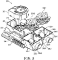
- Figure 3 is an exploded view of an example of a manifold 302, a blower 307, and sensor heads 309 of an aspirating smoke detector device 300, in accordance with one or more embodiments of the present disclosure.
- the aspirating smoke detector device 300 can include a manifold 302.
- the aspirating smoke detector device 300 can include a manifold 302, the manifold including a flow path 304, a blower housing 306, a first sensor head housing 308-1, and a second sensor head housing 308-2.
- the first sensor head housing 308-1 can include a first slot component 386-1.
- the second sensor head housing 308-2 can include a second slot component 386-2.
- the manifold 302 can cover the PCB 312
- the flow path 304 can include the first flow channel 305-1 and the second flow channel 305-2.
- the manifold 302 can include the blower housing 306.
- the blower housing 306 is configured to receive the blower 307.
- the term "blower” refers to a mechanical device for moving gas in a particular direction.
- the blower 307 can be utilized to move gas through the aspirating smoke detector device 300.
- the blower 307 can, in some instances, comprise a ducted housing having a fan that, when spinning, causes gas (e.g., such as air) to flow in a particular direction.
- the blower housing 306 is configured to receive the blower 307 when the blower 307 is oriented in a particular configuration.
- the blower housing 306 can be designed such that the blower 307 can fit into the blower housing 306 in a single orientation. This can prevent the blower 307 from being installed in the blower housing 306 in an incorrect orientation.
- the blower housing 306 can include a blower cover gasket 318.
- the blower cover gasket 318 can be formed on the blower housing 306 by, for instance, molding techniques.
- the blower cover gasket 318 can be, for example, a thermoplastic rubber gasket, among other examples.
- the manifold 302 can additionally include the first sensor head housing 308-1.
- the first sensor head housing 308-1 can be connected to the blower housing 306 via the first flow channel 305-1 and can receive a first sensor head 309-1.
- the term "sensor head” refers to a device to detect events and/or changes in its environment and transmit the detected events and/or changes for processing and/or analysis.
- the sensor heads 309 can be utilized to detect smoke particles in gas transiting through the aspirating smoke detector device 300.
- the first sensor head 309-1 can be a nephelometer (e.g., an aerosol photometer) to measure the concentration of smoke particles in a gas by utilizing light scattered by smoke particles.
- the first sensor head 309-1 can be any other type of smoke detection sensor that detects smoke utilizing gas transiting through the aspirating smoke detector device 300.
- the first sensor head housing 308-1 can be configured to receive a first sensor head 309-1. That is, the first sensor head housing 308-1 is configured to receive the first sensor head 309-1 when the first sensor head 309-1 is oriented in a particular configuration.
- the first sensor head housing 308-1 can be designed such that the first sensor head 309-1 can fit into the first sensor head housing 308-1 in a single orientation. This can prevent the first sensor head 309-1 from being installed in the first sensor head housing 308-1 in an incorrect orientation.
- the first sensor head housing 308-1 can include a first sensor head housing cover gasket 320-1.
- the first sensor head housing cover gasket 320-1 can be formed on the first sensor head housing 308-1 by, for instance, molding techniques.
- the first sensor head housing cover gasket 320-1 can be, for example, a thermoplastic rubber gasket, among other examples.
- the second sensor head housing 308-2 can be connected to the blower housing 306 via the second flow channel 305-2 and can receive a second sensor head 309-2.
- the second sensor head 309-2 can be a nephelometer or any other type of smoke detection sensor that detects smoke utilizing gas transiting through the aspirating smoke detector device 300.
- the second sensor head housing 308-2 can be configured to receive the second sensor head 309-2. That is, the second sensor head housing 308-2 is configured to receive the second sensor head 309-2 when the second sensor head 309-2 is oriented in a particular configuration.
- the second sensor head housing 308-2 can be designed such that the second sensor head 309-2 can fit into the second sensor head housing 308-2 in a single orientation. This can prevent the second sensor head 309-2 from being installed in the second sensor head housing 308-2 in an incorrect orientation.
- the second sensor head housing 308-2 can include a second sensor head housing cover gasket 320-2.
- the second sensor head housing cover gasket 320-2 can be formed on the second sensor head housing 308-2 by, for instance, molding techniques.
- the second sensor head housing cover gasket 320-2 can be, for example, a thermoplastic rubber gasket, among other examples.
- FIG. 4 is perspective view of an example of a housing 422 and a PCB 412 of an aspirating smoke detector device 400, in accordance with one or more embodiments of the present disclosure.
- the housing 422 can house the PCB 412, as is further described herein.
- the aspirating smoke detector device 400 can include a housing 422.
- the term "housing” refers to an outer shell of a device.
- the housing 422 can be a "rear" housing of the aspirating smoke detector device 400 which can house the PCB 412.
- the housing 422 can retain the PCB 412 after assembly of the aspirating smoke detector device 400.
- the PCB 412 can include LEDs 428-1 and 428-2.
- the LEDs 428-1 can be in a 2x2 array configuration to correspond with the 2x2 array configuration of the light pipes (e.g., light pipes 114-1, previously described in connection with Figure 1 ) and the LEDs 428-2 can be in a 1x1 array configuration to correspond with the 1x1 array configuration of the light pipes (e.g., light pipes 114-2, previously described in connection with Figure 1 ).
- the housing 422 can include a fastening mechanism.
- the fastening mechanism can retain the PCB 412 in the housing 422.
- the fastening mechanism can be, for example, a clamp(s), a snap clip, a mechanical fastener (e.g., a bolt, screw, etc.), among other types of fastening mechanisms.
- the housing 422 can include mounting locations.
- the mounting locations can include, for instance, a hole through which a fastener can secure the aspirating smoke detector device 400 to a wall or other object.
- the fastener can be secured to the wall or other object and slipped through the hole of the mounting location such that the housing 422 can rest on the fastener to mount the aspirating smoke detector device 400 to the wall or other object.
- the housing 422 can include a first housing inlet 424-1, a second housing inlet 424-2, and a housing outlet 426.
- the first housing inlet 424-1, the second housing inlet 424-2, and the housing outlet 426 can be apertures in the structure of the housing 422.
- the first housing inlet 424-1 can receive a first sensor head housing inlet
- the second housing inlet 424-2 can receive a second sensor head housing inlet
- the housing outlet 426 can receive a blower housing outlet, as is further described in connection with Figure 5 .
- the housing 422 can further include snap clips 430.
- snap clip refers to a fastening mechanism including a protruding flange having an engagement tooth.
- the snap clips 430 can be deflected when an object to be secured is inserted adjacent to the snap clips 430 and an engagement tooth of each of the snap clips can engage with a surface of the object to secure the object, as is further described in connection with Figure 5 .
- Figure 5 is a perspective view of an example of a housing 522 and a manifold 502 of an aspirating smoke detector device 500 having a blower housing cover 532 and sensor head housing cover 534, in accordance with one or more embodiments of the present disclosure.
- the manifold 502 can include a blower housing 506 and sensor head housings 508.
- the aspirating smoke detector device 500 can be partially assembled.
- the manifold 502 can be connected to the housing 522 via a snap clip (e.g., snap clip 430, previously described in connection with Figure 4 ).
- the snap clip can be deflected when the manifold 502 is inserted into the housing 522 and an engagement tooth of the snap clip can engage with a surface of the manifold 502 to connect the manifold 502 to the housing 522.
- the first sensor head housing inlet 510-1 can be coaxially located with the first housing inlet 524-1.
- the second sensor head housing inlet 510-2 can be coaxially located with the second housing inlet 524-2.
- a blower housing outlet e.g., blower housing outlet 636, as is further described in connection with Figure 6
- the housing outlet e.g., housing outlet 426, previously described in connection with Figure 4 .
- gas can flow into the aspirating smoke detector device 500 via the first sensor head housing inlet 510-1 and/or the second sensor head housing inlet 510-2, to the sensor heads located in the sensor head housings 508, through the flow channels, and out the blower housing outlet, during which time the sensor heads can determine whether the gas includes smoke particles.
- the various housings comprising the manifold 502 can be fluidically sealed.
- the blower housing 506 can receive a blower housing cover 532.
- the blower housing 506 can include a cover gasket (e.g., blower cover gasket 318, previously described in connection with Figure 3 ).
- cover gasket e.g., blower cover gasket 318, previously described in connection with Figure 3 .
- the first sensor head housing 508-1 and the second sensor head housing 508-2 can receive a sensor head housing cover 534 to cover the first sensor head and the second sensor head respectively located therein.
- the first sensor head housing 508-1 and the second sensor head housing 508-2 can include a cover gasket (e.g., first sensor head housing cover gasket 320-1, previously described in connection with Figure 3 ).
- the sensor head housing cover gasket can fluidically seal the first sensor head housing 508-1 and the second sensor head housing 508-2 to the sensor head housing cover 534.
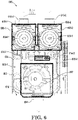
- FIG. 6 is a front view of an example of a manifold 602 of an aspirating smoke detector device 600 having flow channels 605, in accordance with one or more embodiments of the present disclosure.
- the manifold 602 can include a first sensor head housing 608-1, a second sensor head housing 608-2, and a blower housing 606.
- the first sensor head housing 608-1 can include a first sensor head 609-1 and a first sensor head housing inlet 610-1.
- the second sensor head housing 608-2 can include a second sensor head 609-2 and a second sensor head housing inlet 610-2.
- the first sensor head housing 608-1 can include a first slot component 686-1.
- the second sensor head housing 608-2 can include a second slot component 686-2.
- the blower housing 606 can include a blower 607.
- gas can flow through the aspirating smoke detector device 600 as indicated in Figure 6 .
- Gas e.g., such as air from a space in a facility
- Gas can enter the aspirating smoke detector device 600 via the first sensor head housing inlet 610-1 and/or the second sensor head housing inlet 610-2 for smoke particle detection by the first sensor head 609-1 located in the first sensor head housing 608-1 and/or the second sensor head 609-2 located in the second sensor head housing 608-2.
- gas can pass through a first filter (not shown in Figure 6 so as not to obscure embodiments herein) located in the first slot component 686-1 and/or a second filter (not shown in Figure 6 so as not to obscure embodiments herein) located in the second slot component 686-2.
- a filter can include one or more materials known to those of skill in the art that filter out dust and/or debris from the gas entering the first sensor head housing inlet 610-1 and/or the second sensor head housing inlet 610-2.
- filters can include wire mesh filters, woven filters, nonwoven filters, etc.
- the gas can travel through the first flow channel 605-1 and/or the second flow channel 605-2 and exit the aspirating smoke detector device 600 via the blower housing outlet 636.
- the aspirating smoke detector device 600 can include a PCB.
- the PCB can include LEDs that can light up during operation of the aspirating smoke detector device 600 in order to indicate certain information about the operation of the aspirating smoke detector device 600.
- the manifold 602 can further include light pipes 614-1 (e.g., in the 2x2 array configuration) and 614-2 (e.g., in the 1x1 array configuration). The manifold 602 can be positioned over the PCB and cover a portion of the PCB such that the light pipes 614 are oriented above the LEDs included on the PCB.
- the light pipes 614 can be of a transparent material to allow for the light emitted by the LEDs to be transmitted through the light pipes 614 when a cover (e.g., cover 844, as is further described in connection with Figure 8 ) is connected to the manifold 602.
- the light pipes 614 can be, for example, of a transparent acrylic material, although embodiments of the present disclosure are not so limited. Accordingly, the light emitted by the LED can be visible when the aspirating smoke detector device 600 is operational.
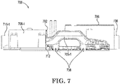
- Figure 7 is a side section view of an example of a manifold 702 having a flow channel 705-1 and a PCB 712 having a pair of ultrasonic sensors 738, in accordance with one or more embodiments of the present disclosure.
- the manifold 702 can include a first sensor head housing 708-1, and a blower housing 706.
- the first sensor head housing 708-1 can be fluidically connected to the blower housing 706 via the first flow channel 705-1.
- the second sensor head housing e.g., second sensor head housing 108-2, 308-2, 508-2, and 608-2, previously described in connection with Figures 1 , 3 , 5 , and 6 , respectively
- a second flow channel e.g., second flow channel 105-2, 305-2, 605-2, previously described in connection with Figures 1 , 3 , and 6 , respectively.
- the first flow channel 705-1 and the second flow channel can include constant cross-sectional dimensions.
- the first flow channel 705-1 and the second flow channel can include constant cross-sectional dimensions (e.g., a constant radius/constant diameter) through a length of the first flow channel 705-1 and the second flow channel.
- the constant cross-sectional dimensions of the first flow channel 705-1 and the second flow channel can help to reduce speed variation and distribution in the flow of the gas through the first flow channel 705-1 and the second flow channel, which can help to increase performance of the blower included in the blower housing 706, as compared with previous approaches.
- the PCB 712 can include a pair of ultrasonic sensors 738 exposed in the first flow channel 705-1. Further, although not illustrated in Figure 7 for clarity and so as not to obscure embodiments of the present disclosure, the PCB 712 can include another pair of ultrasonic sensors exposed in a similar location in the second flow channel as the pair of ultrasonic sensors 738 in the first flow channel 705-1.
- the term "ultrasonic sensor” refers to an electronic component used for measuring the time needed by ultrasonic waves to cover a distance between the sensor and a target, where the target can be another ultrasonic sensor. Using the time of travel (forward and backward) between the pair of ultrasonic sensors, a flow rate of a gas can be measured flowing through the aspirating smoke detector device 700.
- the pair of ultrasonic sensors 738 can measure a gas flow rate of the gas through the aspirating smoke detector device 700. Measuring the gas flow rate of the gas through the aspirating smoke detector device 700 via the pair of ultrasonic sensors 738 can allow for calibration of the blower, as well as ensuring a constant air flow through the aspirating smoke detector device 700.
- FIG 8 is an exploded perspective view of an example of an aspirating smoke detector device 800 having inlet pipes 840, in accordance with one or more embodiments of the present disclosure.
- the aspirating smoke detector device 800 can include a housing 822 and a cover 844.
- the aspirating smoke detector device 800 can be nearly fully assembled.
- the cover 844 e.g., a "front” cover
- the light pipes 814 allow for illumination from the LEDs included on a PCB in the aspirating smoke detector device 800 to be seen when the aspirating smoke detector device 800 is assembled.
- the first housing inlet 824-1 can be connected to a first inlet pipe 840-1 via a first inlet adapter 842-1. Additionally, the second housing inlet 824-2 can be connected to a second inlet pipe 840-2 via a second inlet adapter 842-2.
- the aspirating smoke detector device 800 can draw gas from a location in a facility through a piping network to the aspirating smoke detector device 800 for smoke detection.
- the piping network can include the first inlet pipe 840-1 and/or the second inlet pipe 840-2, which can be connected to the aspirating smoke detector device 800 via the first inlet adapter 842-1 and/or the second inlet adapter 842-2, respectively.
- the first inlet adapter 842-1 and the second inlet adapter 842-2 can be "breakable". If the first inlet pipe 840-1 and the second inlet pipe 840-2 are 25 millimeter (mm) diameter pipes, the first inlet adapter 842-1 and the second inlet adapter 842-2 can be used to accommodate the 25 mm inlet pipes 840. If the first inlet pipe 840-1 and the second inlet pipe 840-2 are 27 mm diameter pipes, the inlet adapters 842 can be removed to accommodate the 27 mm inlet pipes 840.
- the first inlet adapter 842-1 and the second inlet adapter 842-2 can accordingly allow for the accommodation of differently sized piping networks which may vary based on different facilities, different jurisdictions, etc., allowing for ease of installation in different facilities in different locations.
- the first inlet adapter 842-1 can fluidically seal the first inlet pipe 840-1 and the first sensor head housing inlet 810-1
- the second inlet adapter 842-2 can fluidically seal the second inlet pipe 840-2 and the second sensor head housing inlet 810-2.
- Figure 9A is an exploded perspective view of an example of an aspirating smoke detector device 900 having an exhaust pipe 946 and an outlet adapter 948, in accordance with one or more embodiments of the present disclosure.
- the aspirating smoke detector device 900 can include the cover 944 connected to the housing 922.
- the blower housing outlet 936 can be connected to an exhaust pipe 946 via an outlet adapter 948.
- the gas exiting the aspirating smoke detector device 900 can do so through the exhaust pipe 946.
- the outlet adapter 948 can be oriented to receive the exhaust pipe 946. That is, the exhaust pipe 946 can be connected to the outlet adapter 948 by inserting the exhaust pipe 946 into the outlet adapter 948.
- a mesh screen included on the outlet adapter 948 can point "inwards" and prevent particulate or other objects from exiting or entering the aspirating smoke detector device 900 via the blower housing outlet 936.
- Figure 9B is an exploded perspective view of an example of an aspirating smoke detector device 900 having an outlet adapter 948, in accordance with one or more embodiments of the present disclosure.
- the aspirating smoke detector device 900 can include the cover 944 connected to the housing 922.
- the blower housing outlet 936 can be connected to an outlet adapter 948.
- the gas exiting the aspirating smoke detector device 900 can do so through the outlet adapter 948.
- the outlet adapter can be connected to the blower housing outlet 936 by inserting the outlet adapter 948 into the blower housing outlet 936.
- a mesh screen included on the outlet adapter 948 can point "outwards" and prevent particulate or other objects from exiting or entering the aspirating smoke detector device 900 via the blower housing outlet 936.
- the outlet adapter 948 can function as a mesh plug.
- the outlet adapter 948 can be oriented as illustrated in Figure 9B in an embodiment in which the aspirating smoke detector device 900 is not connected to an exhaust pipe (e.g., exhaust pipe 946, previously described in connection with Figure 9A ).
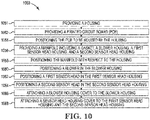
- FIG 10 is an example of a method 1050 of manufacturing of an aspirating smoke detector device, in accordance with one or more embodiments of the present disclosure.
- the method includes providing a housing.
- the housing can be a "rear" housing that can house a PCB and include snap clips to connect various parts of the aspirating smoke detector device thereto.
- the housing can be molded, cast, three-dimensionally (3D) printed, etc.
- the method 1050 includes providing a PCB.
- the PCB can include electrical components utilized in detection of smoke via the aspirating smoke detector device, such as LEDs, switches, buttons, pairs of ultrasonic sensors, as well as processing and memory resources, among other electrical components.
- the method includes positioning the PCB to be housed by the housing.
- the PCB can be positioned and attached to the housing.
- the method 1050 includes providing a manifold including a gasket, a first flow channel and a second flow channel, a blower housing, a first sensor head housing, and a second sensor head housing.
- the manifold can be provided using multi-shot molding techniques. Multiple material types can be utilized in a single mold at one time, including ABS plastic, PMMA plastic, and TPE elastomers, among other materials, in order to provide the manifold. Further, the method 1050 can include an in-mold assembling procedure in conjunction with ultrasonic welding directly in the single-shot molding tool to provide the manifold.
- the method 1050 can include over-molding the gasket to the manifold, another gasket to the blower housing, and a further gasket to the first and second sensor head housings.
- the gaskets can be, for example, thermoplastic rubber gaskets, among other examples.
- the method 1050 includes positioning the manifold with respect to the housing.
- the manifold can be positioned with respect to the housing such that the gasket interfaces with and compresses against the PCB to fluidically seal the manifold to the PCB.
- the method 1050 includes positioning a blower in the blower housing.
- the blower housing can be shaped such that the blower has to be oriented in a particular configuration in order to be received by the blower housing. This can prevent the blower from being positioned/installed in the blower housing in an incorrect orientation and ensures the correct orientation of the blower in the blower housing.
- the method 1050 includes positioning a first sensor head in the first sensor head housing such that the first sensor head is secured in the first sensor head housing.
- the first sensor head housing can be shaped such that the first sensor head also has to be oriented in a particular configuration in order to be received by the first sensor head housing.
- the method 1050 includes positioning a second sensor head in the second sensor head housing such that the second sensor head is secured in the second sensor head housing.
- the second sensor head housing can be shaped such that the second sensor head also has to be oriented in a particular configuration in order to be received by the second sensor head housing.
- the method 1050 can include attaching a blower housing cover to the blower housing.
- the blower housing cover can fluidically seal, via the blower housing gasket, the blower housing in response to attaching the blower housing cover to the blower housing. Since the blower is not secured in the blower housing by a snap clip, the blower housing cover can secure the blower in the blower housing.
- the method 1050 can include attaching a sensor head housing cover to the first sensor head housing and the second sensor head housing.
- the sensor head housing cover can fluidically seal, via the first sensor head housing gasket and the second sensor head housing gasket, the first sensor head housing and the second sensor head housing.
- the method 1050 can include providing an additional "front” cover.
- the "front” cover can be attached to the “rear” cover to complete assembly of the aspirating smoke detector device.
- Figure 11A is a perspective view of an example aspirating smoke detector device package 1170 in accordance with one or more embodiments of the present disclosure.
- Figure 11B is a rear view of an example of a housing 1122 of an aspirating smoke detector device in accordance with one or more embodiments of the present disclosure.
- Figure 11A and Figure 11B may be cumulatively referred to as " Figure 11 .”
- the package 1170 can be made from cardboard, boxboard, containerboard, chipboard, combined board, corrugated board, fiberboard, polymer(s) and/or other suitable packaging material(s).
- the package 1170 is a carton (e.g., box) including a plurality of panels.
- a panel can refer to a side, a top, a bottom, a tongue, and/or other parts of a package.
- the particular configuration of the panels can be any suitable configuration and/or geometry.
- the package 1170 can be a 1-2-3 bottom snap lock carton, a six corner tray, an airplane style straight tuck carton, an airplane tuck end box, a four corner brightwood tray, a tongue & tuck carton, a tuck top auto lock bottom box, a tuck top snap lock bottom box, a rigid box, a regular slotted container (RSC), a half slotted container (HSC), an overlap slotted container (OSC), etc.
- RSC regular slotted container
- HSC half slotted container
- OSC overlap slotted container
- the package 1170 can include a first panel 1172 having a mounting template.
- the mounting template can include a number of mounting indicators.
- the mounting template includes a first mounting indicator 1174-1, a second mounting indicator 1174-2, and a third mounting indicator 1174-3 (referred to cumulatively as "mounting indicators 1174").
- mounting indicators 1174" referred to cumulatively as "mounting indicators 1174".
- three mounting indicators 1174 are shown in the example illustrated in Figure 11 , embodiments herein are not so limited and other quantities of mounting indicators are in accordance with the present disclosure; for example, the example package 1570 illustrated in Figure 15 includes four mounting indicators.
- the mounting indicators 1174 correspond to a number of mounting locations (cumulatively referred to as "mounting locations 1176") on the housing 1122.
- the first mounting indicator 1174-1 corresponds to a first mounting location 1176-1
- the second mounting indicator 1174-2 corresponds to a second mounting location 1176-2
- the third mounting indicator 1174-3 corresponds to a third mounting location 1176-3.
- Each of the mounting locations 1176 can include a surface defining a hole through which a fastener can secure the aspirating smoke detector device to a wall (or other object). The fastener can be secured to the wall or other object and slipped through the hole of the mounting location such that the housing 1122 can rest on the fastener to mount the aspirating smoke detector device to the wall.
- the panel 1172 can be kept on the package 1170 or removed from the package 1170.
- the panel 1172 can be placed on the wall where the smoke detector is desired.
- Mounting holes can be drilled into the wall according to the location of the mounting indicators 1174. Once the holes are drilled, the mounting locations 1176 can be aligned with the drilled holes and the smoke detector can be mounted using fasteners (e.g., screws).
- the mounting indicators 1174 are printed indicia (e.g., circles, crosshairs, etc.) on the panel 1172 such that a drill bit can drill through the printed indica and into the wall behind.
- the mounting indicators 1174 are apertures defined by surfaces extending through the first panel such that a drill bit can be extended through the aperture during drilling.
- Figure 12 is a perspective view of an example panel 1278 of a package 1270 of an aspirating smoke detector device including removable head protectors 1280 in accordance with one or more embodiments of the present disclosure.
- the panel 1278 is a different panel than the panel 1172, previously described in connection with Figure 11 .
- the panel 1278 and the panel 1172 are a same panel.
- the panel 1278 includes a head protector 1280.
- the head protector 1280 can be removed from the panel 1278 and inserted into a slot of the aspirating smoke detector device (discussed further below in connection with Figure 13 ).
- the panel 1278 included two head protectors.
- the head protector 1280 remains in the panel 1278 while a second head protector has been removed leaving a head protector vacancy 1284. It is noted that embodiments of the present disclosure do not limit a quantity of head protectors to a particular number.
- the head protector 1280 can be defined by perforations in the panel 1278.
- the perforations can be made by any suitable manner allowing the head protector 1280 to be removed from the panel 1278 with little or no tools.
- the head protector 1280 is removable by hand.
- the head protector 1280 includes a protrusion 1282.
- the protrusion 1282 which is also shown in Figure 13 , can allow the head protector 1280 to be gripped by a user even when the head protector is inserted in a slot component as described herein. Stated differently, the protrusion 1282 can protrude and/or extend from the aspirating smoke detector device when the head protector 1280 is inserted into the slot.
- the protrusion 1282 is shown as having a semicircular shape, though it is noted that embodiments of the present disclosure are not so limited.
- Figure 13A is a detailed view of a sensor head housing 1308 having a slot component 1386 in accordance with one or more embodiments of the present disclosure.
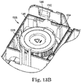
- Figure 13B is a detailed view of the sensor head housing 1308 having a filter 1394 and a head protector 1380 inserted into the slot component 1386 in accordance with one or more embodiments of the present disclosure.
- Figure 13A and Figure 13B may be cumulatively referred to herein as " Figure 13 .”
- the sensor head 1309 is located within the sensor head housing 1308.
- the sensor head housing 1308 can include a slot component 1386.
- the slot component 1386 can include a pair of rails protruding inward and defining a slot.
- the slot component 1386 can define a first portion (e.g., a first slot) and a second portion (e.g., a second slot). As shown in the example illustrated in Figure 13 , the slot component 1386 includes a medial projection 1392 separating a first portion 1388 of the slot component 1386 from a second portion 1390 of the slot component 1386. Stated differently, the slot component 1386 can define two slots.
- a filter 1394 can be inserted into the first portion 1388 of the slot component 1386.
- the filter 1394 can include materials known to those of skill in the art that filter out dust and/or debris from the gas entering the first sensor head housing inlet 610-1 and/or the second sensor head housing inlet 610-2.
- the filter 1394 can be a wire mesh filter, woven filter, nonwoven filter, etc.
- a head protector 1380 can be inserted into the second portion 1390 of the slot component 1386.
- the head protector 1380 can be inserted between the filter 1394 and the sensor head 1309. Accordingly, any dust or debris dislodged by the removal of the filter 1394 can be prevented from reaching the sensor head 1309 by the head protector 1380.
- the head protector 1380 can be removed and the aspirating smoke detector device can resume functioning. Removal of the head protector 1380 can be performed by gripping a protrusion 1382 of the head protector 1380 and withdrawing the head protector 1380 from the second portion 1390 of the slot component 1386.
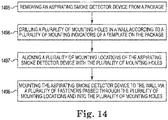
- Figure 14 illustrates a method of utilizing an aspirating smoke detector package in accordance with one or more embodiments of the present disclosure.
- the method includes removing an aspirating smoke detector device from a package.
- the method includes drilling a plurality of mounting holes in a wall according to a plurality of mounting indicators of a template on the package.
- the template can be kept on the package or removed from the package.
- the template can be placed on the wall where the smoke detector is desired.
- Mounting holes can be drilled into the wall according to the location of the mounting indicators.
- the mounting indicators are printed indicia (e.g., circles, crosshairs, etc.) such that a drill bit can drill through the printed indica and into the wall behind.
- the mounting indicators are apertures such that a drill bit can be extended through the aperture during drilling.
- the method includes aligning a plurality of mounting locations of the aspirating smoke detector device with the plurality of mounting holes, and at 1498, the method includes mounting the aspirating smoke detector device to the wall via a plurality of fasteners passed through the plurality of mounting locations and into the plurality of mounting holes.
- suitable fasteners e.g., screws, anchors, etc.
- the method includes steps performed after the mounting of the smoke detector device.
- the method can include removing a head protector from the package, inserting the head protector into a second portion of a slot component, and removing a filter from a first portion of the slot component while the head protector is inserted into the second portion of the slot component.
- Some embodiments include cleaning the filter and re-inserting it before removing the head protector.
- Some embodiments include discarding the filter and inserting a new filter before removing the head protector.
- Figure 15 is a top view of an example unassembled aspirating smoke detector device package 1570 in accordance with one or more embodiments of the present disclosure.
- the package 1570 In an "unassembled" state, the package 1570 is shown laid flat with a plurality of panels. As will be appreciated by those of skill in the art, the panels can be folded, joined, inserted, and/or fastened together to form a three-dimensional package configured to contain an aspirating smoke detector device.
- the package 1570 includes a plurality of head protectors: a first head protector 1580-1, a second head protector 1580-2, a third head protector 1580-3, and a fourth head protector 1580-4 (cumulatively referred to herein as "head protectors 1580").
- the package 1570 includes a mounting template.
- the mounting template can include a number of mounting indicators. For instance, as shown in the example illustrated in Figure 15 , the mounting template includes a first mounting indicator 1574-1, a second mounting indicator 1574-2, a third mounting indicator 1574-3, and a fourth mounting indicator 1574-4 (referred to cumulatively as “mounting indicators 1574").
- embodiments herein include mounting indicators located on more than one panel of the package 1570.
- the package e.g., the panel comprising the mounting indicators 1574.
- the package can include instructions associated with utilizing the mounting indicators 1574, assembling the aspirating smoke detector device, mounting the aspirating smoke detector device, and/or utilizing the head protectors 1580 to protect sensor heads, as described herein.
Landscapes
- Chemical & Material Sciences (AREA)
- Physics & Mathematics (AREA)
- General Physics & Mathematics (AREA)
- Analytical Chemistry (AREA)
- Emergency Management (AREA)
- Business, Economics & Management (AREA)
- Biochemistry (AREA)
- General Health & Medical Sciences (AREA)
- Life Sciences & Earth Sciences (AREA)
- Immunology (AREA)
- Pathology (AREA)
- Health & Medical Sciences (AREA)
- Dispersion Chemistry (AREA)
- Fire-Detection Mechanisms (AREA)
Abstract
Description
- The present disclosure relates to devices, systems, and methods for aspirating smoke detector packaging.
- Large facilities (e.g., buildings), such as commercial facilities, office buildings, hospitals, and the like, may have an alarm system that can be triggered during an emergency situation (e.g., a fire) to warn occupants to evacuate. For example, an alarm system may include a control panel (e.g., a fire control panel) and a plurality of aspirating smoke detector devices located throughout the facility (e.g., on different floors and/or in different rooms of the facility) that detect a hazard event, such as smoke generation (e.g., as the result of a fire or otherwise). The aspirating smoke detector can transmit a signal to the control panel in order to notify a building manager, occupants of the facility, emergency services, and/or others of the hazard event via alarms or other mechanisms.
- Some users attempting to install or maintain previous aspirating smoke detector devices may face difficulties. For instance, some users may be frustrated in attempting to mount previous aspirating smoke detector devices on a wall or other object. In addition, periodic maintenance performed on previous aspirating smoke detector devices carries risks associated with fouling sensitive components with dust or other debris.
-
-
Figure 1 is an exploded view of an example of a portion of an aspirating smoke detector device in accordance with one or more embodiments of the present disclosure. -
Figure 2 is an exploded view of an example of a manifold and a printed circuit board (PCB) of an aspirating smoke detector device in accordance with one or more embodiments of the present disclosure. -
Figure 3 is an exploded view of an example of a manifold, a blower, and sensor heads of an aspirating smoke detector device in accordance with one or more embodiments of the present disclosure. -
Figure 4 is perspective view of an example of a housing and a PCB of an aspirating smoke detector device in accordance with one or more embodiments of the present disclosure. -
Figure 5 is a perspective view of an example of a housing and a manifold of an aspirating smoke detector device having a blower housing cover and sensor head housing covers in accordance with one or more embodiments of the present disclosure. -
Figure 6 is a front view of an example of a manifold of an aspirating smoke detector device having flow channels in accordance with one or more embodiments of the present disclosure. -
Figure 7 is a side section view of an example of a manifold having a flow channel and a PCB having a pair of ultrasonic sensors in accordance with one or more embodiments of the present disclosure. -
Figure 8 is an exploded perspective view of an example of an aspirating smoke detector device having inlet pipes in accordance with one or more embodiments of the present disclosure. -
Figure 9A is an exploded perspective view of an example of an aspirating smoke detector device having an exhaust pipe and an outlet adapter in accordance with one or more embodiments of the present disclosure. -
Figure 9B is an exploded perspective view of an example of an aspirating smoke detector device having an outlet adapter in accordance with one or more embodiments of the present disclosure. -
Figure 10 is an example of a method of manufacturing of an aspirating smoke detector device in accordance with one or more embodiments of the present disclosure. -
Figure 11A is a perspective view of an example aspirating smoke detector device package in accordance with one or more embodiments of the present disclosure. -
Figure 11B is a rear view of an example of a housing of an aspirating smoke detector device in accordance with one or more embodiments of the present disclosure. -
Figure 12 is a perspective view of an example panel of a package of an aspirating smoke detector device including removable head protectors in accordance with one or more embodiments of the present disclosure. -
Figure 13A is a detailed view of a sensor head housing having a slot component in accordance with one or more embodiments of the present disclosure. -
Figure 13B is a detailed view of the sensor head housing having a filter and a head protector inserted into the slot component in accordance with one or more embodiments of the present disclosure. -
Figure 14 illustrates a method of utilizing an aspirating smoke detector package in accordance with one or more embodiments of the present disclosure. -
Figure 15 is a top view of an example unassembled aspirating smoke detector device package in accordance with one or more embodiments of the present disclosure. - Devices, systems, and methods for aspirating smoke detector packaging are described herein. In some examples, one or more embodiments include a package for an aspirating smoke detector device, comprising a plurality of panels, wherein a first panel includes a mounting template having a plurality of mounting indicators, wherein each of the plurality of mounting indicators corresponds to a respective mounting location of the aspirating smoke detector device, and a second panel includes a head protector configured to be removed from the package and inserted into a slot of the aspirating smoke detector device.
- An aspirating smoke detector device can be utilized in a facility to detect a hazard event by detecting the presence of smoke. The aspirating smoke detector device can draw gas (e.g., air, via a blower) from the facility into a sensor through a network of pipes throughout the facility. The sensor can sample the gas in order to determine whether the gas includes smoke particles. In response to detection of smoke particles, the aspirating smoke detector device can transmit a signal to a control panel in the facility to signal detection of smoke particles.
- However, aspirating smoke detector devices may be difficult to assemble and/or install. For example, assembling an aspirating smoke detector device may require assembly of a blower, a sensor head, and/or other components by utilizing a tool to engage with bolts, screws, or other fasteners. Such a design may result in a cumbersome assembly process, which can result in increases in assembly time for the aspirating smoke detector device.
- An aspirating smoke detector device according to the present disclosure can allow for a compact and modular aspirating smoke detector device that can be lower cost and easier to assemble as compared with previous approaches. For example, an aspirating smoke detector device according to the present disclosure can allow for tool-less assembly without the need for fasteners, which can result in decreased assembly time and lower assembly cost as compared with previous approaches.
- Various difficulties faced by users attempting to install and/or maintain an aspirating smoke detector device can be addressed by packing in accordance with embodiments herein. Moreover, these difficulties can be addressed without the need for users to acquire additional tooling, skills, or components because the packaging of the aspirating smoke detector device itself carries helpful solutions with it.
- For instance, some users may be frustrated in attempting to mount previous aspirating smoke detector devices on a wall or other object. The location(s) and or spacing of holes to be drilled may be difficult, particularly with increased numbers of holes. Embodiments of the present disclosure provide a mounting template on a panel of the package containing the aspirating smoke detector device. In some embodiments, the mounting template includes a plurality of mounting indicators. These mounting indicators align with mounting locations (e.g., holes) on a rear surface of a housing of the aspirating smoke detector device. Thus, a user can place the template on the surface where the aspirating smoke detector device is to be mounted. The mounting indicators can indicate where holes should be drilled for mounting the aspirating smoke detector device via fasteners (e.g., screws). In some embodiments, drilling can be performed directly through the mounting indicators.
- In addition, periodic maintenance performed on previous aspirating smoke detector devices carries risks associated with fouling sensitive components with dust or other debris. In one example, removing a filter for periodic cleaning or replacement can dislodge dust that can fall, or otherwise deposit, on a sensor head. Dust on a sensor head can negatively affect the operation of the sensor head. Embodiments of the present disclosure provide a number of removable head protectors on a panel of the package containing the aspirating smoke detector device. A head protector can be defined by perforations in the panel, for instance, which can allow the head protector to be removed by hand (e.g., without the use of a tool). In some embodiments, the head protector can be inserted into a slot of a sensor head housing between the filter and the sensor head. Accordingly, any dust or debris dislodged by the removal of the filter can be prevented from reaching the sensor head by the head protector. After cleaning or replacement of the filter is completed, the head protector can be removed and the aspirating smoke detector device can resume functioning.
- In the following detailed description, reference is made to the accompanying drawings that form a part hereof. The drawings show by way of illustration how one or more embodiments of the disclosure may be practiced.
- These embodiments are described in sufficient detail to enable those of ordinary skill in the art to practice one or more embodiments of this disclosure. It is to be understood that other embodiments may be utilized and that process, electrical, and/or structural changes may be made without departing from the scope of the present disclosure.
- As will be appreciated, elements shown in the various embodiments herein can be added, exchanged, combined, and/or eliminated so as to provide a number of additional embodiments of the present disclosure. The proportion and the relative scale of the elements provided in the figures are intended to illustrate the embodiments of the present disclosure and should not be taken in a limiting sense.
- The figures herein follow a numbering convention in which the first digit or digits correspond to the drawing figure number and the remaining digits identify an element or component in the drawing. Similar elements or components between different figures may be identified by the use of similar digits. For example, 102 may reference element "02" in
Figure 1 , and a similar element may be referenced as 202 inFigure 2 . - As used herein, "a", "an", or "a number of" something can refer to one or more such things, while "a plurality of" something can refer to more than one such things. For example, "a number of components" can refer to one or more components, while "a plurality of components" can refer to more than one component.
-
Figure 1 is an exploded view of an example of a portion of an aspiratingsmoke detector device 100, in accordance with one or more embodiments of the present disclosure. The aspiratingsmoke detector device 100 can include a manifold 102 and aPCB 112. - As illustrated in
Figure 1 , the aspiratingsmoke detector device 100 can include a printed circuit board (PCB) 112. As used herein, the term "PCB" refers to a device to mechanically support and/or electrically connect electrical components via conductive traces. ThePCB 112 can, therefore, include electrical components utilized in detection of smoke via the aspiratingsmoke detector device 100. For example, although not illustrated inFigure 1 for clarity and so as not to obscure embodiments of the present disclosure, the aspiratingsmoke detector device 100 can include a blower and sensor head housings. ThePCB 112 can be utilized to control the blower (e.g., the speed of the blower), receive signals from the sensor head housings, etc. ThePCB 112 can, accordingly, be utilized to control operation of the aspiratingsmoke detector device 100 to detect smoke particles in a gas flowing through the aspiratingsmoke detector device 100 and transmit a signal to a control panel in response to detection of smoke particles in the gas. ThePCB 112 can include buttons (e.g., not illustrated inFigure 1 ), light emitting diodes (LEDs), as are further described in connection withFigure 6 , among other electrical components. - As shown in the exploded view of
Figure 1 , the aspiratingsmoke detector device 100 can further include amanifold 102. As used herein, the term "manifold" refers to a device including at least one inlet and at least one outlet. For example, the manifold 102 can make up a portion of the aspiratingsmoke detector device 100 and can include various parts, including aflow path 104, ablower housing 106, a first sensor head housing 108-1, and a second sensor head housing 108-2, as are further described herein. - The manifold 102 can be manufactured of a plastic material. For example, the manifold 102 can be manufactured from acrylonitrile butadiene styrene (ABS) plastic, poly(methyl methacrylate) (PMMA) plastic, thermoplastic elastomers (TPE), among other types of plastic materials. Further, the manifold 102 can be made of any other type of material (e.g., metal, carbon fiber, etc.). The manifold 102 can be manufactured via multi-shot molding techniques, among other manufacturing techniques, as is further described in connection with
Figure 10 . - A
flow path 104 can be included as part of themanifold 102. Theflow path 104 can include a first flow channel 105-1 and a second flow channel 105-2 (referred to collectively herein as flow channels 105). The flow channels 105 can allow for the flow of gas through the aspiratingsmoke detector device 100. For instance, gas can flow into and out of different portions of the aspiratingsmoke detector device 100 through the flow channels 105 for smoke detection, as is further described herein. - The manifold 102 can include light pipes 114-1 and 114-2. As used herein, the term "light pipe" refers to a device to transmit light for the purpose of illumination. The light pipes 114 can be of a transparent material to allow light (e.g., from an LED of the PCB 112) to be transmitted, as is further described in connection with
Figures 6 and8 . The light pipes 114-1 can be in a 2x2 array configuration and the light pipes 114-2 can be in a 1x1 array configuration. - The manifold 102 can include a
blower housing 106. Theblower housing 106 can be configured to receive a blower (e.g., not illustrated inFigure 1 ). The blower can operate to draw gas into and cause gas to flow through the aspiratingsmoke detector device 100. Theblower housing 106 can include ablower housing outlet 111. The gas flowing through the aspiratingsmoke detector device 100 can exit the aspirating smoke detector device through theblower housing outlet 111. - The first flow channel 105-1 can connect the
blower housing 106 to a first sensor head housing 108-1. The first sensor head housing 108-1 can be configured to receive a sensor head (e.g., not illustrated inFigure 1 ). The first sensor head housing 108-1 can include a first sensor head housing inlet 110-1. The blower can operate to draw gas into a sensor head located in the first sensor head housing 108-1 via the first sensor head housing inlet 110-1 and out of the first sensor head housing 108-1 via the first flow channel 105-1 for detection of smoke particles in the gas. - Similar to the first flow channel 105-1, the second flow channel 105-2 can connect the
blower housing 106 to a second sensor head housing 108-2. The second sensor head housing 108-2 can also be configured to receive a sensor head (e.g., not illustrated inFigure 1 ). The second sensor head housing 108-2 can include a second sensor head housing inlet 110-2. The blower can operate to draw gas into another sensor head located in the second sensor head housing 108-2 via the second sensor head housing inlet 110-2 and out of the second sensor head housing 108-2 via the second flow channel 105-2 for detection of smoke particles in the gas. - The first sensor head housing 108-1 can include a first slot component 186-1, and the second sensor head housing 108-2 can include a second slot component 186-2 (sometimes cumulatively referred to as "slot components 186"). The slot components 186, which are described in more detail below, can receive a filter and a head protector as described herein.
- As illustrated in
Figure 1 , the manifold 102 can further include agasket 116. As used herein, the term "gasket" refers to a device located around an area of another device to make the area impervious to the transition of fluid through or around the device. For example, thegasket 116 can be located on a "back" side of the manifold 102 which is to interface (e.g., rest against) thePCB 112. Thegasket 116 can fluidically seal the manifold 102 to thePCB 112, as is further described in connection withFigure 2 . -
Figure 2 is an exploded view of an example of a manifold 202 and a printed circuit board (PCB) 212 of an aspiratingsmoke detector device 200, in accordance with one or more embodiments of the present disclosure. The manifold 202 can include agasket 216. - As previously described in connection with
Figure 1 , the manifold 202 can include agasket 216. Thegasket 216 can be utilized to fluidically seal the manifold 202 to thePCB 212. For example, when the aspiratingsmoke detector device 200 is assembled, the manifold 202 can be positioned adjacent to (e.g., resting against) thePCB 212. When the manifold 202 is positioned adjacent to thePCB 212, thegasket 216 can be compressed against thePCB 212 to cause thegasket 216 to fluidically seal the manifold 202 to thePCB 212. - In some examples, the
gasket 216 can be a thermo-plastic rubber gasket. Thegasket 216 can be created on the manifold 202 via molding techniques, as is further described in connection withFigure 10 . Further, although thegasket 216 is described as a thermo-plastic rubber gasket, embodiments of the present disclosure are not so limited. For example, thegasket 216 can be any other material that can fluidically seal the manifold 202 to thePCB 212. - Fluidically sealing the manifold 202 to the
PCB 212 can prevent substances from transiting between thegasket 216 into a space between the manifold 202 and thePCB 212. Such a fluidically sealed space can prevent moisture from entering the space. Accordingly, thegasket 216 can guard against moisture interacting with thePCB 212, preventing shorting of the electrical components of thePCB 212, preventing corrosion of thePCB 212, etc. -
Figure 3 is an exploded view of an example of a manifold 302, ablower 307, and sensor heads 309 of an aspiratingsmoke detector device 300, in accordance with one or more embodiments of the present disclosure. The aspiratingsmoke detector device 300 can include amanifold 302. - As previously described in connection with
Figure 1 , the aspiratingsmoke detector device 300 can include a manifold 302, the manifold including aflow path 304, ablower housing 306, a first sensor head housing 308-1, and a second sensor head housing 308-2. The first sensor head housing 308-1 can include a first slot component 386-1. The second sensor head housing 308-2 can include a second slot component 386-2. The manifold 302 can cover the PCB312The flow path 304 can include the first flow channel 305-1 and the second flow channel 305-2. - As illustrated in
Figure 3 , the manifold 302 can include theblower housing 306. Theblower housing 306 is configured to receive theblower 307. As used herein, the term "blower" refers to a mechanical device for moving gas in a particular direction. For example, theblower 307 can be utilized to move gas through the aspiratingsmoke detector device 300. Theblower 307 can, in some instances, comprise a ducted housing having a fan that, when spinning, causes gas (e.g., such as air) to flow in a particular direction. - The
blower housing 306 is configured to receive theblower 307 when theblower 307 is oriented in a particular configuration. For example, theblower housing 306 can be designed such that theblower 307 can fit into theblower housing 306 in a single orientation. This can prevent theblower 307 from being installed in theblower housing 306 in an incorrect orientation. - The
blower housing 306 can include ablower cover gasket 318. Theblower cover gasket 318 can be formed on theblower housing 306 by, for instance, molding techniques. Theblower cover gasket 318 can be, for example, a thermoplastic rubber gasket, among other examples. - The manifold 302 can additionally include the first sensor head housing 308-1. The first sensor head housing 308-1 can be connected to the
blower housing 306 via the first flow channel 305-1 and can receive a first sensor head 309-1. As used herein, the term "sensor head" refers to a device to detect events and/or changes in its environment and transmit the detected events and/or changes for processing and/or analysis. For example, the sensor heads 309 can be utilized to detect smoke particles in gas transiting through the aspiratingsmoke detector device 300. In some examples, the first sensor head 309-1 can be a nephelometer (e.g., an aerosol photometer) to measure the concentration of smoke particles in a gas by utilizing light scattered by smoke particles. However, the first sensor head 309-1 can be any other type of smoke detection sensor that detects smoke utilizing gas transiting through the aspiratingsmoke detector device 300. - The first sensor head housing 308-1 can be configured to receive a first sensor head 309-1. That is, the first sensor head housing 308-1 is configured to receive the first sensor head 309-1 when the first sensor head 309-1 is oriented in a particular configuration. For example, the first sensor head housing 308-1 can be designed such that the first sensor head 309-1 can fit into the first sensor head housing 308-1 in a single orientation. This can prevent the first sensor head 309-1 from being installed in the first sensor head housing 308-1 in an incorrect orientation.
- The first sensor head housing 308-1 can include a first sensor head housing cover gasket 320-1. The first sensor head housing cover gasket 320-1 can be formed on the first sensor head housing 308-1 by, for instance, molding techniques. The first sensor head housing cover gasket 320-1 can be, for example, a thermoplastic rubber gasket, among other examples.
- Similar to the first sensor head housing 308-1, the second sensor head housing 308-2 can be connected to the
blower housing 306 via the second flow channel 305-2 and can receive a second sensor head 309-2. The second sensor head 309-2 can be a nephelometer or any other type of smoke detection sensor that detects smoke utilizing gas transiting through the aspiratingsmoke detector device 300. Additionally, the second sensor head housing 308-2 can be configured to receive the second sensor head 309-2. That is, the second sensor head housing 308-2 is configured to receive the second sensor head 309-2 when the second sensor head 309-2 is oriented in a particular configuration. For example, the second sensor head housing 308-2 can be designed such that the second sensor head 309-2 can fit into the second sensor head housing 308-2 in a single orientation. This can prevent the second sensor head 309-2 from being installed in the second sensor head housing 308-2 in an incorrect orientation. - The second sensor head housing 308-2 can include a second sensor head housing cover gasket 320-2. The second sensor head housing cover gasket 320-2 can be formed on the second sensor head housing 308-2 by, for instance, molding techniques. The second sensor head housing cover gasket 320-2 can be, for example, a thermoplastic rubber gasket, among other examples.
-
Figure 4 is perspective view of an example of ahousing 422 and aPCB 412 of an aspiratingsmoke detector device 400, in accordance with one or more embodiments of the present disclosure. Thehousing 422 can house thePCB 412, as is further described herein. - As illustrated in
Figure 4 , the aspiratingsmoke detector device 400 can include ahousing 422. As used herein, the term "housing" refers to an outer shell of a device. Thehousing 422 can be a "rear" housing of the aspiratingsmoke detector device 400 which can house thePCB 412. For example, thehousing 422 can retain thePCB 412 after assembly of the aspiratingsmoke detector device 400. ThePCB 412 can include LEDs 428-1 and 428-2. The LEDs 428-1 can be in a 2x2 array configuration to correspond with the 2x2 array configuration of the light pipes (e.g., light pipes 114-1, previously described in connection withFigure 1 ) and the LEDs 428-2 can be in a 1x1 array configuration to correspond with the 1x1 array configuration of the light pipes (e.g., light pipes 114-2, previously described in connection withFigure 1 ). - Although not illustrated in
Figure 4 for clarity and so as not to obscure embodiments of the present disclosure, thehousing 422 can include a fastening mechanism. The fastening mechanism can retain thePCB 412 in thehousing 422. The fastening mechanism can be, for example, a clamp(s), a snap clip, a mechanical fastener (e.g., a bolt, screw, etc.), among other types of fastening mechanisms. - Additionally, although not illustrated in
Figure 4 for clarity and so as not to obscure embodiments of the present disclosure, thehousing 422 can include mounting locations. The mounting locations can include, for instance, a hole through which a fastener can secure the aspiratingsmoke detector device 400 to a wall or other object. The fastener can be secured to the wall or other object and slipped through the hole of the mounting location such that thehousing 422 can rest on the fastener to mount the aspiratingsmoke detector device 400 to the wall or other object. - The
housing 422 can include a first housing inlet 424-1, a second housing inlet 424-2, and ahousing outlet 426. The first housing inlet 424-1, the second housing inlet 424-2, and thehousing outlet 426 can be apertures in the structure of thehousing 422. The first housing inlet 424-1 can receive a first sensor head housing inlet, the second housing inlet 424-2 can receive a second sensor head housing inlet, and thehousing outlet 426 can receive a blower housing outlet, as is further described in connection withFigure 5 . - As illustrated in
Figure 4 , thehousing 422 can further include snap clips 430. As used herein, the term "snap clip" refers to a fastening mechanism including a protruding flange having an engagement tooth. The snap clips 430 can be deflected when an object to be secured is inserted adjacent to the snap clips 430 and an engagement tooth of each of the snap clips can engage with a surface of the object to secure the object, as is further described in connection withFigure 5 . -
Figure 5 is a perspective view of an example of ahousing 522 and amanifold 502 of an aspiratingsmoke detector device 500 having ablower housing cover 532 and sensorhead housing cover 534, in accordance with one or more embodiments of the present disclosure. The manifold 502 can include ablower housing 506 and sensor head housings 508. - In the embodiment illustrated in
Figure 5 , the aspiratingsmoke detector device 500 can be partially assembled. For example, the manifold 502 can be connected to thehousing 522 via a snap clip (e.g.,snap clip 430, previously described in connection withFigure 4 ). The snap clip can be deflected when the manifold 502 is inserted into thehousing 522 and an engagement tooth of the snap clip can engage with a surface of the manifold 502 to connect the manifold 502 to thehousing 522. - When the manifold 502 is connected to the
housing 522, the first sensor head housing inlet 510-1 can be coaxially located with the first housing inlet 524-1. Additionally, the second sensor head housing inlet 510-2 can be coaxially located with the second housing inlet 524-2. Further, although not illustrated inFigure 5 for clarity and so as not to obscure embodiments of the present disclosure, a blower housing outlet (e.g.,blower housing outlet 636, as is further described in connection withFigure 6 ) can be coaxially located with the housing outlet (e.g.,housing outlet 426, previously described in connection withFigure 4 ). Accordingly, gas can flow into the aspiratingsmoke detector device 500 via the first sensor head housing inlet 510-1 and/or the second sensor head housing inlet 510-2, to the sensor heads located in the sensor head housings 508, through the flow channels, and out the blower housing outlet, during which time the sensor heads can determine whether the gas includes smoke particles. - In order to ensure the gas flowing through the aspirating
smoke detector device 500 is not mixed with gas located outside the aspiratingsmoke detector device 500, the various housings comprising the manifold 502 can be fluidically sealed. For example, theblower housing 506 can receive ablower housing cover 532. As previously described in connection withFigure 3 , theblower housing 506 can include a cover gasket (e.g.,blower cover gasket 318, previously described in connection withFigure 3 ). When theblower housing cover 532 is connected to theblower housing 506, the blower cover gasket can fluidically seal theblower housing 506 to theblower housing cover 532. - Similar to the
blower housing 506, the first sensor head housing 508-1 and the second sensor head housing 508-2 can receive a sensorhead housing cover 534 to cover the first sensor head and the second sensor head respectively located therein. As previously described in connection withFigure 3 , the first sensor head housing 508-1 and the second sensor head housing 508-2 can include a cover gasket (e.g., first sensor head housing cover gasket 320-1, previously described in connection withFigure 3 ). When the sensorhead housing cover 534 is connected to the first sensor head housing 508-1 and the second sensor head housing 508-2, the sensor head housing cover gasket can fluidically seal the first sensor head housing 508-1 and the second sensor head housing 508-2 to the sensorhead housing cover 534. -
Figure 6 is a front view of an example of amanifold 602 of an aspiratingsmoke detector device 600 having flow channels 605, in accordance with one or more embodiments of the present disclosure. The manifold 602 can include a first sensor head housing 608-1, a second sensor head housing 608-2, and ablower housing 606. The first sensor head housing 608-1 can include a first sensor head 609-1 and a first sensor head housing inlet 610-1. The second sensor head housing 608-2 can include a second sensor head 609-2 and a second sensor head housing inlet 610-2. The first sensor head housing 608-1 can include a first slot component 686-1. The second sensor head housing 608-2 can include a second slot component 686-2. Theblower housing 606 can include ablower 607. - When the
blower 607 is operating, gas can flow through the aspiratingsmoke detector device 600 as indicated inFigure 6 . Gas (e.g., such as air from a space in a facility) can enter the aspiratingsmoke detector device 600 via the first sensor head housing inlet 610-1 and/or the second sensor head housing inlet 610-2 for smoke particle detection by the first sensor head 609-1 located in the first sensor head housing 608-1 and/or the second sensor head 609-2 located in the second sensor head housing 608-2. Before reaching the first sensor head 609-1 and/or the second sensor head 609-2, gas can pass through a first filter (not shown inFigure 6 so as not to obscure embodiments herein) located in the first slot component 686-1 and/or a second filter (not shown inFigure 6 so as not to obscure embodiments herein) located in the second slot component 686-2. A filter, as referred to herein, can include one or more materials known to those of skill in the art that filter out dust and/or debris from the gas entering the first sensor head housing inlet 610-1 and/or the second sensor head housing inlet 610-2. For instance, in some embodiments, filters can include wire mesh filters, woven filters, nonwoven filters, etc. - Following smoke particle detection by the first sensor head 609-1 and/or the second sensor head 609-2, the gas can travel through the first flow channel 605-1 and/or the second flow channel 605-2 and exit the aspirating
smoke detector device 600 via theblower housing outlet 636. - As previously described herein, the aspirating
smoke detector device 600 can include a PCB. The PCB can include LEDs that can light up during operation of the aspiratingsmoke detector device 600 in order to indicate certain information about the operation of the aspiratingsmoke detector device 600. Further, as previously described herein, the manifold 602 can further include light pipes 614-1 (e.g., in the 2x2 array configuration) and 614-2 (e.g., in the 1x1 array configuration). The manifold 602 can be positioned over the PCB and cover a portion of the PCB such that the light pipes 614 are oriented above the LEDs included on the PCB. The light pipes 614 can be of a transparent material to allow for the light emitted by the LEDs to be transmitted through the light pipes 614 when a cover (e.g.,cover 844, as is further described in connection withFigure 8 ) is connected to themanifold 602. The light pipes 614 can be, for example, of a transparent acrylic material, although embodiments of the present disclosure are not so limited. Accordingly, the light emitted by the LED can be visible when the aspiratingsmoke detector device 600 is operational. -
Figure 7 is a side section view of an example of a manifold 702 having a flow channel 705-1 and aPCB 712 having a pair ofultrasonic sensors 738, in accordance with one or more embodiments of the present disclosure. The manifold 702 can include a first sensor head housing 708-1, and ablower housing 706. - The first sensor head housing 708-1 can be fluidically connected to the
blower housing 706 via the first flow channel 705-1. Further, although not illustrated inFigure 7 for clarity and so as not to obscure embodiments of the present disclosure, the second sensor head housing (e.g., second sensor head housing 108-2, 308-2, 508-2, and 608-2, previously described in connection withFigures 1 ,3 ,5 , and6 , respectively) can be fluidically connected to theblower housing 706 via a second flow channel (e.g., second flow channel 105-2, 305-2, 605-2, previously described in connection withFigures 1 ,3 , and6 , respectively). - The first flow channel 705-1 and the second flow channel can include constant cross-sectional dimensions. For example, the first flow channel 705-1 and the second flow channel can include constant cross-sectional dimensions (e.g., a constant radius/constant diameter) through a length of the first flow channel 705-1 and the second flow channel. The constant cross-sectional dimensions of the first flow channel 705-1 and the second flow channel can help to reduce speed variation and distribution in the flow of the gas through the first flow channel 705-1 and the second flow channel, which can help to increase performance of the blower included in the
blower housing 706, as compared with previous approaches. - The
PCB 712 can include a pair ofultrasonic sensors 738 exposed in the first flow channel 705-1. Further, although not illustrated inFigure 7 for clarity and so as not to obscure embodiments of the present disclosure, thePCB 712 can include another pair of ultrasonic sensors exposed in a similar location in the second flow channel as the pair ofultrasonic sensors 738 in the first flow channel 705-1. As used herein, the term "ultrasonic sensor" refers to an electronic component used for measuring the time needed by ultrasonic waves to cover a distance between the sensor and a target, where the target can be another ultrasonic sensor. Using the time of travel (forward and backward) between the pair of ultrasonic sensors, a flow rate of a gas can be measured flowing through the aspiratingsmoke detector device 700. - The pair of
ultrasonic sensors 738 can measure a gas flow rate of the gas through the aspiratingsmoke detector device 700. Measuring the gas flow rate of the gas through the aspiratingsmoke detector device 700 via the pair ofultrasonic sensors 738 can allow for calibration of the blower, as well as ensuring a constant air flow through the aspiratingsmoke detector device 700. -
Figure 8 is an exploded perspective view of an example of an aspiratingsmoke detector device 800 having inlet pipes 840, in accordance with one or more embodiments of the present disclosure. The aspiratingsmoke detector device 800 can include ahousing 822 and acover 844. - As illustrated in
Figure 8 , the aspiratingsmoke detector device 800 can be nearly fully assembled. The cover 844 (e.g., a "front" cover) can be connected to thehousing 822 via snap clip(s). When thecover 844 is connected to thehousing 822, thelight pipes 814 allow for illumination from the LEDs included on a PCB in the aspiratingsmoke detector device 800 to be seen when the aspiratingsmoke detector device 800 is assembled. - The first housing inlet 824-1 can be connected to a first inlet pipe 840-1 via a first inlet adapter 842-1. Additionally, the second housing inlet 824-2 can be connected to a second inlet pipe 840-2 via a second inlet adapter 842-2. For example, when installed, the aspirating
smoke detector device 800 can draw gas from a location in a facility through a piping network to the aspiratingsmoke detector device 800 for smoke detection. The piping network can include the first inlet pipe 840-1 and/or the second inlet pipe 840-2, which can be connected to the aspiratingsmoke detector device 800 via the first inlet adapter 842-1 and/or the second inlet adapter 842-2, respectively. - The first inlet adapter 842-1 and the second inlet adapter 842-2 can be "breakable". If the first inlet pipe 840-1 and the second inlet pipe 840-2 are 25 millimeter (mm) diameter pipes, the first inlet adapter 842-1 and the second inlet adapter 842-2 can be used to accommodate the 25 mm inlet pipes 840. If the first inlet pipe 840-1 and the second inlet pipe 840-2 are 27 mm diameter pipes, the inlet adapters 842 can be removed to accommodate the 27 mm inlet pipes 840. The first inlet adapter 842-1 and the second inlet adapter 842-2 can accordingly allow for the accommodation of differently sized piping networks which may vary based on different facilities, different jurisdictions, etc., allowing for ease of installation in different facilities in different locations. As such, the first inlet adapter 842-1 can fluidically seal the first inlet pipe 840-1 and the first sensor head housing inlet 810-1 and the second inlet adapter 842-2 can fluidically seal the second inlet pipe 840-2 and the second sensor head housing inlet 810-2.
-
Figure 9A is an exploded perspective view of an example of an aspiratingsmoke detector device 900 having anexhaust pipe 946 and anoutlet adapter 948, in accordance with one or more embodiments of the present disclosure. The aspiratingsmoke detector device 900 can include thecover 944 connected to thehousing 922. - As illustrated in
Figure 9A , theblower housing outlet 936 can be connected to anexhaust pipe 946 via anoutlet adapter 948. The gas exiting the aspiratingsmoke detector device 900 can do so through theexhaust pipe 946. - As illustrated in
Figure 9A , theoutlet adapter 948 can be oriented to receive theexhaust pipe 946. That is, theexhaust pipe 946 can be connected to theoutlet adapter 948 by inserting theexhaust pipe 946 into theoutlet adapter 948. A mesh screen included on theoutlet adapter 948 can point "inwards" and prevent particulate or other objects from exiting or entering the aspiratingsmoke detector device 900 via theblower housing outlet 936. -
Figure 9B is an exploded perspective view of an example of an aspiratingsmoke detector device 900 having anoutlet adapter 948, in accordance with one or more embodiments of the present disclosure. The aspiratingsmoke detector device 900 can include thecover 944 connected to thehousing 922. - As illustrated in
Figure 9B , theblower housing outlet 936 can be connected to anoutlet adapter 948. The gas exiting the aspiratingsmoke detector device 900 can do so through theoutlet adapter 948. - The outlet adapter can be connected to the
blower housing outlet 936 by inserting theoutlet adapter 948 into theblower housing outlet 936. A mesh screen included on theoutlet adapter 948 can point "outwards" and prevent particulate or other objects from exiting or entering the aspiratingsmoke detector device 900 via theblower housing outlet 936. In such a manner, theoutlet adapter 948 can function as a mesh plug. Theoutlet adapter 948 can be oriented as illustrated inFigure 9B in an embodiment in which the aspiratingsmoke detector device 900 is not connected to an exhaust pipe (e.g.,exhaust pipe 946, previously described in connection withFigure 9A ). -
Figure 10 is an example of amethod 1050 of manufacturing of an aspirating smoke detector device, in accordance with one or more embodiments of the present disclosure. At 1051, the method includes providing a housing. The housing can be a "rear" housing that can house a PCB and include snap clips to connect various parts of the aspirating smoke detector device thereto. The housing can be molded, cast, three-dimensionally (3D) printed, etc. - At 1052, the
method 1050 includes providing a PCB. The PCB can include electrical components utilized in detection of smoke via the aspirating smoke detector device, such as LEDs, switches, buttons, pairs of ultrasonic sensors, as well as processing and memory resources, among other electrical components. - At 1052, the method includes positioning the PCB to be housed by the housing. For example, the PCB can be positioned and attached to the housing.
- At 1056, the
method 1050 includes providing a manifold including a gasket, a first flow channel and a second flow channel, a blower housing, a first sensor head housing, and a second sensor head housing. The manifold can be provided using multi-shot molding techniques. Multiple material types can be utilized in a single mold at one time, including ABS plastic, PMMA plastic, and TPE elastomers, among other materials, in order to provide the manifold. Further, themethod 1050 can include an in-mold assembling procedure in conjunction with ultrasonic welding directly in the single-shot molding tool to provide the manifold. Further, themethod 1050 can include over-molding the gasket to the manifold, another gasket to the blower housing, and a further gasket to the first and second sensor head housings. The gaskets can be, for example, thermoplastic rubber gaskets, among other examples. - At 1058, the
method 1050 includes positioning the manifold with respect to the housing. The manifold can be positioned with respect to the housing such that the gasket interfaces with and compresses against the PCB to fluidically seal the manifold to the PCB. - At 1060, the
method 1050 includes positioning a blower in the blower housing. The blower housing can be shaped such that the blower has to be oriented in a particular configuration in order to be received by the blower housing. This can prevent the blower from being positioned/installed in the blower housing in an incorrect orientation and ensures the correct orientation of the blower in the blower housing. - At 1062, the
method 1050 includes positioning a first sensor head in the first sensor head housing such that the first sensor head is secured in the first sensor head housing. The first sensor head housing can be shaped such that the first sensor head also has to be oriented in a particular configuration in order to be received by the first sensor head housing. - At 1064, the
method 1050 includes positioning a second sensor head in the second sensor head housing such that the second sensor head is secured in the second sensor head housing. The second sensor head housing can be shaped such that the second sensor head also has to be oriented in a particular configuration in order to be received by the second sensor head housing. - At 1066, the
method 1050 can include attaching a blower housing cover to the blower housing. The blower housing cover can fluidically seal, via the blower housing gasket, the blower housing in response to attaching the blower housing cover to the blower housing. Since the blower is not secured in the blower housing by a snap clip, the blower housing cover can secure the blower in the blower housing. - At 1068, the
method 1050 can include attaching a sensor head housing cover to the first sensor head housing and the second sensor head housing. The sensor head housing cover can fluidically seal, via the first sensor head housing gasket and the second sensor head housing gasket, the first sensor head housing and the second sensor head housing. - Lastly, the
method 1050 can include providing an additional "front" cover. The "front" cover can be attached to the "rear" cover to complete assembly of the aspirating smoke detector device. -
Figure 11A is a perspective view of an example aspirating smokedetector device package 1170 in accordance with one or more embodiments of the present disclosure.Figure 11B is a rear view of an example of ahousing 1122 of an aspirating smoke detector device in accordance with one or more embodiments of the present disclosure.Figure 11A andFigure 11B may be cumulatively referred to as "Figure 11 ." - The
package 1170 can be made from cardboard, boxboard, containerboard, chipboard, combined board, corrugated board, fiberboard, polymer(s) and/or other suitable packaging material(s). In some embodiments, thepackage 1170 is a carton (e.g., box) including a plurality of panels. A panel can refer to a side, a top, a bottom, a tongue, and/or other parts of a package. The particular configuration of the panels can be any suitable configuration and/or geometry. For instance, thepackage 1170 can be a 1-2-3 bottom snap lock carton, a six corner tray, an airplane style straight tuck carton, an airplane tuck end box, a four corner brightwood tray, a tongue & tuck carton, a tuck top auto lock bottom box, a tuck top snap lock bottom box, a rigid box, a regular slotted container (RSC), a half slotted container (HSC), an overlap slotted container (OSC), etc. - As shown in
Figure 11 , thepackage 1170 can include afirst panel 1172 having a mounting template. The mounting template can include a number of mounting indicators. For instance, as shown in the example illustrated inFigure 11 , the mounting template includes a first mounting indicator 1174-1, a second mounting indicator 1174-2, and a third mounting indicator 1174-3 (referred to cumulatively as "mounting indicators 1174"). It is noted that while three mounting indicators 1174 are shown in the example illustrated inFigure 11 , embodiments herein are not so limited and other quantities of mounting indicators are in accordance with the present disclosure; for example, theexample package 1570 illustrated inFigure 15 includes four mounting indicators. - The mounting indicators 1174 correspond to a number of mounting locations (cumulatively referred to as "mounting locations 1176") on the
housing 1122. The first mounting indicator 1174-1 corresponds to a first mounting location 1176-1, the second mounting indicator 1174-2 corresponds to a second mounting location 1176-2, and the third mounting indicator 1174-3 corresponds to a third mounting location 1176-3. Each of the mounting locations 1176 can include a surface defining a hole through which a fastener can secure the aspirating smoke detector device to a wall (or other object). The fastener can be secured to the wall or other object and slipped through the hole of the mounting location such that thehousing 1122 can rest on the fastener to mount the aspirating smoke detector device to the wall. - The
panel 1172 can be kept on thepackage 1170 or removed from thepackage 1170. Thepanel 1172 can be placed on the wall where the smoke detector is desired. Mounting holes can be drilled into the wall according to the location of the mounting indicators 1174. Once the holes are drilled, the mounting locations 1176 can be aligned with the drilled holes and the smoke detector can be mounted using fasteners (e.g., screws). In some embodiments, the mounting indicators 1174 are printed indicia (e.g., circles, crosshairs, etc.) on thepanel 1172 such that a drill bit can drill through the printed indica and into the wall behind. In some embodiments, the mounting indicators 1174 are apertures defined by surfaces extending through the first panel such that a drill bit can be extended through the aperture during drilling. -
Figure 12 is a perspective view of anexample panel 1278 of apackage 1270 of an aspirating smoke detector device includingremovable head protectors 1280 in accordance with one or more embodiments of the present disclosure. In some embodiments, thepanel 1278 is a different panel than thepanel 1172, previously described in connection withFigure 11 . In some embodiments, thepanel 1278 and thepanel 1172 are a same panel. - As shown in
Figure 12 , thepanel 1278 includes ahead protector 1280. Thehead protector 1280 can be removed from thepanel 1278 and inserted into a slot of the aspirating smoke detector device (discussed further below in connection withFigure 13 ). As shown in the example illustrated inFigure 12 , thepanel 1278 included two head protectors. Thehead protector 1280 remains in thepanel 1278 while a second head protector has been removed leaving ahead protector vacancy 1284. It is noted that embodiments of the present disclosure do not limit a quantity of head protectors to a particular number. - The
head protector 1280 can be defined by perforations in thepanel 1278. The perforations can be made by any suitable manner allowing thehead protector 1280 to be removed from thepanel 1278 with little or no tools. For example, in some embodiments, thehead protector 1280 is removable by hand. As shown inFigure 12 , thehead protector 1280 includes aprotrusion 1282. Theprotrusion 1282, which is also shown inFigure 13 , can allow thehead protector 1280 to be gripped by a user even when the head protector is inserted in a slot component as described herein. Stated differently, theprotrusion 1282 can protrude and/or extend from the aspirating smoke detector device when thehead protector 1280 is inserted into the slot. Theprotrusion 1282 is shown as having a semicircular shape, though it is noted that embodiments of the present disclosure are not so limited. -
Figure 13A is a detailed view of asensor head housing 1308 having aslot component 1386 in accordance with one or more embodiments of the present disclosure.Figure 13B is a detailed view of thesensor head housing 1308 having afilter 1394 and ahead protector 1380 inserted into theslot component 1386 in accordance with one or more embodiments of the present disclosure.Figure 13A andFigure 13B may be cumulatively referred to herein as "Figure 13 ." As shown inFigure 13 , thesensor head 1309 is located within thesensor head housing 1308. Thesensor head housing 1308 can include aslot component 1386. Theslot component 1386 can include a pair of rails protruding inward and defining a slot. In some embodiments theslot component 1386 can define a first portion (e.g., a first slot) and a second portion (e.g., a second slot). As shown in the example illustrated inFigure 13 , theslot component 1386 includes amedial projection 1392 separating afirst portion 1388 of theslot component 1386 from asecond portion 1390 of theslot component 1386. Stated differently, theslot component 1386 can define two slots. - As shown in
Figure 13B , afilter 1394 can be inserted into thefirst portion 1388 of theslot component 1386. Thefilter 1394 can include materials known to those of skill in the art that filter out dust and/or debris from the gas entering the first sensor head housing inlet 610-1 and/or the second sensor head housing inlet 610-2. For instance, in some embodiments, thefilter 1394 can be a wire mesh filter, woven filter, nonwoven filter, etc. - As shown in
Figure 13B , ahead protector 1380 can be inserted into thesecond portion 1390 of theslot component 1386. Thehead protector 1380 can be inserted between thefilter 1394 and thesensor head 1309. Accordingly, any dust or debris dislodged by the removal of thefilter 1394 can be prevented from reaching thesensor head 1309 by thehead protector 1380. After cleaning or replacement of thefilter 1394 is completed, thehead protector 1380 can be removed and the aspirating smoke detector device can resume functioning. Removal of thehead protector 1380 can be performed by gripping aprotrusion 1382 of thehead protector 1380 and withdrawing thehead protector 1380 from thesecond portion 1390 of theslot component 1386. -
Figure 14 illustrates a method of utilizing an aspirating smoke detector package in accordance with one or more embodiments of the present disclosure. At 1495, the method includes removing an aspirating smoke detector device from a package. At 1496, the method includes drilling a plurality of mounting holes in a wall according to a plurality of mounting indicators of a template on the package. In some embodiments, the template can be kept on the package or removed from the package. The template can be placed on the wall where the smoke detector is desired. Mounting holes can be drilled into the wall according to the location of the mounting indicators. In some embodiments, the mounting indicators are printed indicia (e.g., circles, crosshairs, etc.) such that a drill bit can drill through the printed indica and into the wall behind. In some embodiments, the mounting indicators are apertures such that a drill bit can be extended through the aperture during drilling. - At 1497, the method includes aligning a plurality of mounting locations of the aspirating smoke detector device with the plurality of mounting holes, and at 1498, the method includes mounting the aspirating smoke detector device to the wall via a plurality of fasteners passed through the plurality of mounting locations and into the plurality of mounting holes. As previously discussed, once the holes are drilled, the mounting locations can be aligned with the drilled holes and the smoke detector can be mounted using suitable fasteners (e.g., screws, anchors, etc.).
- In some embodiments, the method includes steps performed after the mounting of the smoke detector device. For instance, the method can include removing a head protector from the package, inserting the head protector into a second portion of a slot component, and removing a filter from a first portion of the slot component while the head protector is inserted into the second portion of the slot component. Some embodiments include cleaning the filter and re-inserting it before removing the head protector. Some embodiments include discarding the filter and inserting a new filter before removing the head protector.
-
Figure 15 is a top view of an example unassembled aspirating smokedetector device package 1570 in accordance with one or more embodiments of the present disclosure. In an "unassembled" state, thepackage 1570 is shown laid flat with a plurality of panels. As will be appreciated by those of skill in the art, the panels can be folded, joined, inserted, and/or fastened together to form a three-dimensional package configured to contain an aspirating smoke detector device. - As shown in
Figure 15 , thepackage 1570 includes a plurality of head protectors: a first head protector 1580-1, a second head protector 1580-2, a third head protector 1580-3, and a fourth head protector 1580-4 (cumulatively referred to herein as "head protectors 1580"). Additionally, as shown inFigure 15 , thepackage 1570 includes a mounting template. The mounting template can include a number of mounting indicators. For instance, as shown in the example illustrated inFigure 15 , the mounting template includes a first mounting indicator 1574-1, a second mounting indicator 1574-2, a third mounting indicator 1574-3, and a fourth mounting indicator 1574-4 (referred to cumulatively as "mounting indicators 1574"). As shown in the example illustrated inFigure 15 , embodiments herein include mounting indicators located on more than one panel of thepackage 1570. Additionally, in some embodiments, such as that shown in the example illustrated inFigure 15 , the package (e.g., the panel comprising the mounting indicators 1574) can include instructions associated with utilizing the mounting indicators 1574, assembling the aspirating smoke detector device, mounting the aspirating smoke detector device, and/or utilizing the head protectors 1580 to protect sensor heads, as described herein. - Although specific embodiments have been illustrated and described herein, those of ordinary skill in the art will appreciate that any arrangement calculated to achieve the same techniques can be substituted for the specific embodiments shown. This disclosure is intended to cover any and all adaptations or variations of various embodiments of the disclosure.
- It is to be understood that the above description has been made in an illustrative fashion, and not a restrictive one. Combinations of the above embodiments, and other embodiments not specifically described herein will be apparent to those of skill in the art upon reviewing the above description.
- The scope of the various embodiments of the disclosure includes any other applications in which the above structures and methods are used. Therefore, the scope of various embodiments of the disclosure should be determined with reference to the appended claims, along with the full range of equivalents to which such claims are entitled.
- In the foregoing Detailed Description, various features are grouped together in example embodiments illustrated in the figures for the purpose of streamlining the disclosure. This method of disclosure is not to be interpreted as reflecting an intention that the embodiments of the disclosure require more features than are expressly recited in each claim.
- Rather, as the following claims reflect, inventive subject matter lies in less than all features of a single disclosed embodiment. Thus, the following claims are hereby incorporated into the Detailed Description, with each claim standing on its own as a separate embodiment.
Claims (15)
- A package (1170, 1270, 1570) for an aspirating smoke detector device (100, 200, 300, 400, 500, 600, 700, 800, 900) comprising:
a plurality of panels (1172, 1278), wherein:a first panel (1172) includes a mounting template having a plurality of mounting indicators (1174, 1574), wherein each of the plurality of mounting indicators (1174, 1574) corresponds to a respective mounting location (1176) of the aspirating smoke detector device (100, 200, 300, 400, 500, 600, 700, 800, 900); anda second panel (1278) includes a head protector (1280, 1380, 1580) configured to be removed from the package (1170, 1270, 1570) and inserted into a slot (186, 386, 686, 1386) of the aspirating smoke detector device (100, 200, 300, 400, 500, 600, 700, 800, 900). - The package (1170, 1270, 1570) of claim 1, wherein the package (1170, 1270, 1570) is a cardboard package (1170, 1270, 1570).
- the package (1170, 1270, 1570) of claim 1, wherein the first panel (1172) and the second panel (1278) are a same panel.
- The package (1170, 1270, 1570) of claim 1, wherein the first panel (1172) and the second panel (1278) are different panels.
- The package (1170, 1270, 1570) of claim 1, wherein the plurality of mounting indicators (1174, 1574) are printed on the first panel (1172).
- The package (1170, 1270, 1570) of claim 1, wherein the plurality of mounting indicators (1174, 1574) are apertures defined by surfaces extending through the first panel (1172).
- The package (1170, 1270, 1570) of claim 1, wherein the plurality of mounting indicators (1174, 1574) include three mounting indicators.
- The package (1170, 1270, 1570) of claim 7, wherein the three mounting indicators (1174, 1574) include:a first mounting indicator (1174-1, 1574-1) located on a first half of the first panel (1172);a second mounting indicator (1174-2, 1574-2) located on a second half of the first panel (1172); anda third mounting indicator (1174-3, 1574-3) located on the second half of the first panel (1172).
- The package (1170, 1270, 1570) of claim 1, wherein the head protector (1280, 1380, 1580) includes a protrusion (1282, 1382) located along an edge of the head protector (1280, 1380, 1580).
- The package (1170, 1270, 1570) of claim 9, wherein the protrusion (1282, 1382) is configured to protrude from the aspirating smoke detector device (100, 200, 300, 400, 500, 600, 700, 800, 900) when the head protector (1280, 1380, 1580) is inserted into the slot (186, 386, 686, 1386) of the aspirating smoke detector device (100, 200, 300, 400, 500, 600, 700, 800, 900).
- The package (1170, 1270, 1570) of claim 1, wherein the head protector (1280, 1380, 1580) is defined by a plurality of perforations through the second panel (1278).
- A system, comprising:an aspirating smoke detector device (100, 200, 300, 400, 500, 600, 700, 800, 900); anda package (1170, 1270, 1570) configured to contain the aspirating smoke detector device (100, 200, 300, 400, 500, 600, 700, 800, 900);wherein the aspirating smoke detector device (100, 200, 300, 400, 500, 600, 700, 800, 900) includes:a plurality of mounting locations (1176);a sensor head housing (108, 308, 508, 608, 1308) wherein the sensor head housing (108, 308, 508, 608, 1308) includes a housing inlet (110, 510, 610, 810) a housing outlet (105, 305, 605, 705), and a slot component (186, 386, 686, 1386);a sensor head (309, 609, 1309) within the sensor head housing (108, 308, 508, 608, 1308);a blower (307, 607) configured to draw gas into the sensor head housing (108, 308, 508, 608, 1308) through the housing inlet (110, 510, 610, 810) and out of the sensor head housing (108, 308, 508, 608, 1308) through the housing outlet (105, 305, 605, 705); anda filter (1394) retained in the sensor head housing (108, 308, 508, 608, 1308) by a first portion (1388) of the slot component (186, 386, 686, 1386); andwherein the package (1170, 1270, 1570) includes:a mounting template having a plurality of mounting indicators (1174, 1574), wherein each of the plurality of mounting indicators (1174, 1574) corresponds to one of the plurality of mounting locations (1176); anda head protector (1280, 1380, 1580) configured to be removed from the package (1170, 1270, 1570) and inserted into a second portion (1390) of the slot component (186, 386, 686, 1386).
- The system of claim 12, wherein the second portion (1390) of the slot component (186, 386, 686, 1386) is between the first portion (1388) of the slot component (186, 386, 686, 1386) and the sensor head (309, 609, 1309).
- The system of claim 12, wherein a plurality of mounting locations are located on a housing (422, 522, 822, 922, 1122) of the aspirating smoke detector device (100, 200, 300, 400, 500, 600, 700, 800, 900).
- The system of claim 12, wherein the head protector (1280, 1380, 1580) includes a protrusion (1282, 1382) configured to extend above the second portion of the slot component when the head protector (1280, 1380, 1580) is inserted into the second portion (1390) of the slot component (186, 386, 686, 1386).
Applications Claiming Priority (1)
| Application Number | Priority Date | Filing Date | Title |
|---|---|---|---|
| US17/335,308 US11867532B2 (en) | 2021-06-01 | 2021-06-01 | Aspirating smoke detector packaging |
Publications (2)
| Publication Number | Publication Date |
|---|---|
| EP4099285A1 true EP4099285A1 (en) | 2022-12-07 |
| EP4099285B1 EP4099285B1 (en) | 2024-02-21 |
Family
ID=81877745
Family Applications (1)
| Application Number | Title | Priority Date | Filing Date |
|---|---|---|---|
| EP22176832.8A Active EP4099285B1 (en) | 2021-06-01 | 2022-06-01 | Aspirating smoke detector packaging |
Country Status (3)
| Country | Link |
|---|---|
| US (1) | US11867532B2 (en) |
| EP (1) | EP4099285B1 (en) |
| CN (1) | CN115436242B (en) |
Cited By (4)
| Publication number | Priority date | Publication date | Assignee | Title |
|---|---|---|---|---|
| US20220381592A1 (en) * | 2021-06-01 | 2022-12-01 | Honeywell International Inc. | Aspirating smoke detector packaging |
| EP4530610A1 (en) | 2023-09-28 | 2025-04-02 | Wagner Group GmbH | Basic device with particle detection unit and filters |
| EP4531016A1 (en) | 2023-09-28 | 2025-04-02 | Wagner Group GmbH | Particle detection unit having a detection chamber and flow guiding component |
| WO2025068490A1 (en) | 2023-09-28 | 2025-04-03 | Wagner Group Gmbh | Particle detection unit with detection chamber and flow-guiding component |
Families Citing this family (1)
| Publication number | Priority date | Publication date | Assignee | Title |
|---|---|---|---|---|
| USD991067S1 (en) * | 2020-10-17 | 2023-07-04 | Honeywell International Inc. | Modular aspirated smoke, gas, and air quality monitoring system device |
Citations (4)
| Publication number | Priority date | Publication date | Assignee | Title |
|---|---|---|---|---|
| EP0774742A2 (en) * | 1995-11-14 | 1997-05-21 | Wagner Alarm- und Sicherungssysteme GmbH | Fire detector |
| DE10114729A1 (en) * | 2001-03-22 | 2002-10-02 | Rittal Gmbh & Co Kg | Switchgear cabinet with smoke alarm device, includes fan for drawing air out from interior of switchgear cabinet into housing via inlet aperture in housing wall |
| CN110613912A (en) * | 2018-06-19 | 2019-12-27 | 山东省科学院自动化研究所 | Small-space fire very early detection and nondestructive fire extinguishing device and method |
| RU2726142C1 (en) * | 2020-01-31 | 2020-07-09 | Общество с ограниченной ответственностью "Пожтехника" | Aspiration fire detector (versions) |
Family Cites Families (23)
| Publication number | Priority date | Publication date | Assignee | Title |
|---|---|---|---|---|
| KR900002606B1 (en) * | 1986-05-02 | 1990-04-20 | 주식회사 금성사 | Video head protection device |
| DE4428694C2 (en) | 1994-08-12 | 1996-06-20 | Wagner Alarm Sicherung | Air pressure compensated fire detection device and method |
| CA2291203A1 (en) | 1998-12-04 | 2000-06-04 | George A. Schoenfelder | Aspirated detector with flow sensor |
| IL134630A0 (en) * | 2000-02-20 | 2001-04-30 | Spintech Technologies Ltd | Lens protection mechanism |
| DE20205194U1 (en) * | 2002-04-03 | 2002-08-08 | Everday Technology Co., Ltd., Taipeh/T'ai-pei | Smoke collection case |
| DE102004034908A1 (en) * | 2004-07-19 | 2006-03-16 | Airbus Deutschland Gmbh | Smoke alarm system for aircraft, has camera module and smoke warning transmitter which are arranged in housing |
| US20100194575A1 (en) * | 2009-01-30 | 2010-08-05 | Carlos Pedrejon Rodriguez | Dual channel aspirated detector |
| ES2394872T3 (en) | 2010-07-15 | 2013-02-06 | Siemens Schweiz Ag | Detection of obstructions and interruptions of an aspirated smoke detector (ASD) |
| CN202642445U (en) * | 2012-06-05 | 2013-01-02 | 珠海格力电器股份有限公司 | Packaging piece |
| ES2451915R1 (en) * | 2012-09-27 | 2014-06-02 | Utc Fire & Security Americas Corporation, Inc. | MODULAR SMOKE DETECTION SYSTEM AND PROCEDURE FOR MOUNTING A SMOKE DETECTION SYSTEM |
| WO2014209897A2 (en) * | 2013-06-25 | 2014-12-31 | Cummins Filtration Ip, Inc | Fluid quality monitoring and filtration system |
| US9373238B2 (en) * | 2013-07-19 | 2016-06-21 | Honeywell International Inc. | Multi-channel aspirated smoke detector |
| CN203480636U (en) * | 2013-10-18 | 2014-03-12 | 温州港湾安全科技有限公司 | Electrical fire monitoring detector positioning structure in panel installation type |
| US10115280B2 (en) * | 2014-06-26 | 2018-10-30 | Life Safety Distribution Ag | Detector with optical block |
| US9824564B2 (en) * | 2015-12-14 | 2017-11-21 | Honeywell International Inc. | Aspirated smoke detector with improved optical chamber |
| US10877011B2 (en) | 2016-06-29 | 2020-12-29 | Nexceris, Llc | Systems and methods for monitoring for a gas analyte |
| CN205845239U (en) * | 2016-07-27 | 2016-12-28 | 郑州森鹏电子技术有限公司 | A kind of active inspiration formula smoke detector |
| WO2020041224A1 (en) * | 2018-08-20 | 2020-02-27 | Yale University | Shoulder mountable real-time air quality measurement device and air quality device calibration system |
| US11231403B2 (en) * | 2018-10-16 | 2022-01-25 | Novinium, Inc. | Methods of using dilution of a second type to calibrate one or more sensors |
| CN211044472U (en) * | 2019-11-08 | 2020-07-17 | 内蒙古电力(集团)有限责任公司薛家湾供电局 | Air filtering device suitable for air suction type smoke sensing fire detection system |
| CN211927627U (en) * | 2020-04-28 | 2020-11-13 | 北京睿创智源科技有限公司 | Online monitoring system for oil smoke concentration of catering industry |
| US11867532B2 (en) * | 2021-06-01 | 2024-01-09 | Honeywell International Inc. | Aspirating smoke detector packaging |
| US11900776B2 (en) * | 2021-06-01 | 2024-02-13 | Honeywell International Inc. | Lid of an aspirating smoke detector device |
-
2021
- 2021-06-01 US US17/335,308 patent/US11867532B2/en active Active
-
2022
- 2022-06-01 EP EP22176832.8A patent/EP4099285B1/en active Active
- 2022-06-01 CN CN202210618753.3A patent/CN115436242B/en active Active
Patent Citations (4)
| Publication number | Priority date | Publication date | Assignee | Title |
|---|---|---|---|---|
| EP0774742A2 (en) * | 1995-11-14 | 1997-05-21 | Wagner Alarm- und Sicherungssysteme GmbH | Fire detector |
| DE10114729A1 (en) * | 2001-03-22 | 2002-10-02 | Rittal Gmbh & Co Kg | Switchgear cabinet with smoke alarm device, includes fan for drawing air out from interior of switchgear cabinet into housing via inlet aperture in housing wall |
| CN110613912A (en) * | 2018-06-19 | 2019-12-27 | 山东省科学院自动化研究所 | Small-space fire very early detection and nondestructive fire extinguishing device and method |
| RU2726142C1 (en) * | 2020-01-31 | 2020-07-09 | Общество с ограниченной ответственностью "Пожтехника" | Aspiration fire detector (versions) |
Cited By (6)
| Publication number | Priority date | Publication date | Assignee | Title |
|---|---|---|---|---|
| US20220381592A1 (en) * | 2021-06-01 | 2022-12-01 | Honeywell International Inc. | Aspirating smoke detector packaging |
| US11867532B2 (en) * | 2021-06-01 | 2024-01-09 | Honeywell International Inc. | Aspirating smoke detector packaging |
| EP4530610A1 (en) | 2023-09-28 | 2025-04-02 | Wagner Group GmbH | Basic device with particle detection unit and filters |
| EP4531016A1 (en) | 2023-09-28 | 2025-04-02 | Wagner Group GmbH | Particle detection unit having a detection chamber and flow guiding component |
| WO2025068484A1 (en) | 2023-09-28 | 2025-04-03 | Wagner Group Gmbh | Base device with particle detection unit and filters |
| WO2025068490A1 (en) | 2023-09-28 | 2025-04-03 | Wagner Group Gmbh | Particle detection unit with detection chamber and flow-guiding component |
Also Published As
| Publication number | Publication date |
|---|---|
| US20220381592A1 (en) | 2022-12-01 |
| US11867532B2 (en) | 2024-01-09 |
| CN115436242B (en) | 2025-11-14 |
| CN115436242A (en) | 2022-12-06 |
| EP4099285B1 (en) | 2024-02-21 |
Similar Documents
| Publication | Publication Date | Title |
|---|---|---|
| EP4099285B1 (en) | Aspirating smoke detector packaging | |
| EP4099286B1 (en) | Aspirating smoke detector device | |
| CA2489933C (en) | Fire detector | |
| EP2172916B1 (en) | Photoelectric smoke detector | |
| EP2960878A1 (en) | Detector with optical block | |
| EP0717385A1 (en) | Light scattering smoke sensor | |
| CA2660270A1 (en) | Combination smoke and heat detector | |
| CA1278839C (en) | Monitor display system | |
| CN112185055A (en) | Alarm device | |
| AU2011300546A1 (en) | Duct detector | |
| US11888258B2 (en) | Sealed electrical connector | |
| CN115439994B (en) | Cover for an aspirated smoke detector device | |
| CN210895746U (en) | Explosion-proof smoke, carbon monoxide and temperature composite detector | |
| GB2620007A (en) | Optical detection devices | |
| JP3766912B2 (en) | Fire detector | |
| JP3362324B2 (en) | Fire detector | |
| EP1784629B1 (en) | Fluid detector | |
| JPH1058U (en) | Flame detector protective cover | |
| CN117760643A (en) | Quick detection reaction unit intakes | |
| CN207851032U (en) | A kind of dust-proof gas detector structure | |
| WO2025076388A1 (en) | Smoke chamber | |
| CN222947574U (en) | Deflector and sorting system | |
| CN217388677U (en) | Sliding gesture infrared induction switch | |
| EP4290233A2 (en) | Emi protected enclosure with integral indicator-light guides for gas detectors | |
| JP3407093B2 (en) | Fire detector |
Legal Events
| Date | Code | Title | Description |
|---|---|---|---|
| PUAI | Public reference made under article 153(3) epc to a published international application that has entered the european phase |
Free format text: ORIGINAL CODE: 0009012 |
|
| STAA | Information on the status of an ep patent application or granted ep patent |
Free format text: STATUS: REQUEST FOR EXAMINATION WAS MADE |
|
| 17P | Request for examination filed |
Effective date: 20220601 |
|
| AK | Designated contracting states |
Kind code of ref document: A1 Designated state(s): AL AT BE BG CH CY CZ DE DK EE ES FI FR GB GR HR HU IE IS IT LI LT LU LV MC MK MT NL NO PL PT RO RS SE SI SK SM TR |
|
| P01 | Opt-out of the competence of the unified patent court (upc) registered |
Effective date: 20230523 |
|
| GRAJ | Information related to disapproval of communication of intention to grant by the applicant or resumption of examination proceedings by the epo deleted |
Free format text: ORIGINAL CODE: EPIDOSDIGR1 |
|
| STAA | Information on the status of an ep patent application or granted ep patent |
Free format text: STATUS: GRANT OF PATENT IS INTENDED |
|
| GRAP | Despatch of communication of intention to grant a patent |
Free format text: ORIGINAL CODE: EPIDOSNIGR1 |
|
| RIC1 | Information provided on ipc code assigned before grant |
Ipc: G08B 17/113 20060101ALI20230913BHEP Ipc: G08B 17/10 20060101AFI20230913BHEP |
|
| INTG | Intention to grant announced |
Effective date: 20231005 |
|
| GRAS | Grant fee paid |
Free format text: ORIGINAL CODE: EPIDOSNIGR3 |
|
| GRAA | (expected) grant |
Free format text: ORIGINAL CODE: 0009210 |
|
| STAA | Information on the status of an ep patent application or granted ep patent |
Free format text: STATUS: THE PATENT HAS BEEN GRANTED |
|
| AK | Designated contracting states |
Kind code of ref document: B1 Designated state(s): AL AT BE BG CH CY CZ DE DK EE ES FI FR GB GR HR HU IE IS IT LI LT LU LV MC MK MT NL NO PL PT RO RS SE SI SK SM TR |
|
| REG | Reference to a national code |
Ref country code: GB Ref legal event code: FG4D |
|
| REG | Reference to a national code |
Ref country code: CH Ref legal event code: EP |
|
| REG | Reference to a national code |
Ref country code: IE Ref legal event code: FG4D |
|
| REG | Reference to a national code |
Ref country code: DE Ref legal event code: R096 Ref document number: 602022002019 Country of ref document: DE |
|
| REG | Reference to a national code |
Ref country code: LT Ref legal event code: MG9D |
|
| REG | Reference to a national code |
Ref country code: NL Ref legal event code: MP Effective date: 20240221 |
|
| PG25 | Lapsed in a contracting state [announced via postgrant information from national office to epo] |
Ref country code: IS Free format text: LAPSE BECAUSE OF FAILURE TO SUBMIT A TRANSLATION OF THE DESCRIPTION OR TO PAY THE FEE WITHIN THE PRESCRIBED TIME-LIMIT Effective date: 20240621 |
|
| PG25 | Lapsed in a contracting state [announced via postgrant information from national office to epo] |
Ref country code: LT Free format text: LAPSE BECAUSE OF FAILURE TO SUBMIT A TRANSLATION OF THE DESCRIPTION OR TO PAY THE FEE WITHIN THE PRESCRIBED TIME-LIMIT Effective date: 20240221 |
|
| PG25 | Lapsed in a contracting state [announced via postgrant information from national office to epo] |
Ref country code: GR Free format text: LAPSE BECAUSE OF FAILURE TO SUBMIT A TRANSLATION OF THE DESCRIPTION OR TO PAY THE FEE WITHIN THE PRESCRIBED TIME-LIMIT Effective date: 20240522 |
|
| REG | Reference to a national code |
Ref country code: AT Ref legal event code: MK05 Ref document number: 1659782 Country of ref document: AT Kind code of ref document: T Effective date: 20240221 |
|
| PG25 | Lapsed in a contracting state [announced via postgrant information from national office to epo] |
Ref country code: RS Free format text: LAPSE BECAUSE OF FAILURE TO SUBMIT A TRANSLATION OF THE DESCRIPTION OR TO PAY THE FEE WITHIN THE PRESCRIBED TIME-LIMIT Effective date: 20240521 Ref country code: HR Free format text: LAPSE BECAUSE OF FAILURE TO SUBMIT A TRANSLATION OF THE DESCRIPTION OR TO PAY THE FEE WITHIN THE PRESCRIBED TIME-LIMIT Effective date: 20240221 Ref country code: NL Free format text: LAPSE BECAUSE OF FAILURE TO SUBMIT A TRANSLATION OF THE DESCRIPTION OR TO PAY THE FEE WITHIN THE PRESCRIBED TIME-LIMIT Effective date: 20240221 |
|
| PG25 | Lapsed in a contracting state [announced via postgrant information from national office to epo] |
Ref country code: ES Free format text: LAPSE BECAUSE OF FAILURE TO SUBMIT A TRANSLATION OF THE DESCRIPTION OR TO PAY THE FEE WITHIN THE PRESCRIBED TIME-LIMIT Effective date: 20240221 |
|
| PG25 | Lapsed in a contracting state [announced via postgrant information from national office to epo] |
Ref country code: AT Free format text: LAPSE BECAUSE OF FAILURE TO SUBMIT A TRANSLATION OF THE DESCRIPTION OR TO PAY THE FEE WITHIN THE PRESCRIBED TIME-LIMIT Effective date: 20240221 |
|
| PG25 | Lapsed in a contracting state [announced via postgrant information from national office to epo] |
Ref country code: RS Free format text: LAPSE BECAUSE OF FAILURE TO SUBMIT A TRANSLATION OF THE DESCRIPTION OR TO PAY THE FEE WITHIN THE PRESCRIBED TIME-LIMIT Effective date: 20240521 Ref country code: NO Free format text: LAPSE BECAUSE OF FAILURE TO SUBMIT A TRANSLATION OF THE DESCRIPTION OR TO PAY THE FEE WITHIN THE PRESCRIBED TIME-LIMIT Effective date: 20240521 Ref country code: NL Free format text: LAPSE BECAUSE OF FAILURE TO SUBMIT A TRANSLATION OF THE DESCRIPTION OR TO PAY THE FEE WITHIN THE PRESCRIBED TIME-LIMIT Effective date: 20240221 Ref country code: LT Free format text: LAPSE BECAUSE OF FAILURE TO SUBMIT A TRANSLATION OF THE DESCRIPTION OR TO PAY THE FEE WITHIN THE PRESCRIBED TIME-LIMIT Effective date: 20240221 Ref country code: IS Free format text: LAPSE BECAUSE OF FAILURE TO SUBMIT A TRANSLATION OF THE DESCRIPTION OR TO PAY THE FEE WITHIN THE PRESCRIBED TIME-LIMIT Effective date: 20240621 Ref country code: HR Free format text: LAPSE BECAUSE OF FAILURE TO SUBMIT A TRANSLATION OF THE DESCRIPTION OR TO PAY THE FEE WITHIN THE PRESCRIBED TIME-LIMIT Effective date: 20240221 Ref country code: GR Free format text: LAPSE BECAUSE OF FAILURE TO SUBMIT A TRANSLATION OF THE DESCRIPTION OR TO PAY THE FEE WITHIN THE PRESCRIBED TIME-LIMIT Effective date: 20240522 Ref country code: FI Free format text: LAPSE BECAUSE OF FAILURE TO SUBMIT A TRANSLATION OF THE DESCRIPTION OR TO PAY THE FEE WITHIN THE PRESCRIBED TIME-LIMIT Effective date: 20240221 Ref country code: ES Free format text: LAPSE BECAUSE OF FAILURE TO SUBMIT A TRANSLATION OF THE DESCRIPTION OR TO PAY THE FEE WITHIN THE PRESCRIBED TIME-LIMIT Effective date: 20240221 Ref country code: BG Free format text: LAPSE BECAUSE OF FAILURE TO SUBMIT A TRANSLATION OF THE DESCRIPTION OR TO PAY THE FEE WITHIN THE PRESCRIBED TIME-LIMIT Effective date: 20240221 Ref country code: AT Free format text: LAPSE BECAUSE OF FAILURE TO SUBMIT A TRANSLATION OF THE DESCRIPTION OR TO PAY THE FEE WITHIN THE PRESCRIBED TIME-LIMIT Effective date: 20240221 |
|
| PG25 | Lapsed in a contracting state [announced via postgrant information from national office to epo] |
Ref country code: PL Free format text: LAPSE BECAUSE OF FAILURE TO SUBMIT A TRANSLATION OF THE DESCRIPTION OR TO PAY THE FEE WITHIN THE PRESCRIBED TIME-LIMIT Effective date: 20240221 Ref country code: PT Free format text: LAPSE BECAUSE OF FAILURE TO SUBMIT A TRANSLATION OF THE DESCRIPTION OR TO PAY THE FEE WITHIN THE PRESCRIBED TIME-LIMIT Effective date: 20240621 |
|
| PG25 | Lapsed in a contracting state [announced via postgrant information from national office to epo] |
Ref country code: SE Free format text: LAPSE BECAUSE OF FAILURE TO SUBMIT A TRANSLATION OF THE DESCRIPTION OR TO PAY THE FEE WITHIN THE PRESCRIBED TIME-LIMIT Effective date: 20240221 Ref country code: PT Free format text: LAPSE BECAUSE OF FAILURE TO SUBMIT A TRANSLATION OF THE DESCRIPTION OR TO PAY THE FEE WITHIN THE PRESCRIBED TIME-LIMIT Effective date: 20240621 Ref country code: PL Free format text: LAPSE BECAUSE OF FAILURE TO SUBMIT A TRANSLATION OF THE DESCRIPTION OR TO PAY THE FEE WITHIN THE PRESCRIBED TIME-LIMIT Effective date: 20240221 Ref country code: LV Free format text: LAPSE BECAUSE OF FAILURE TO SUBMIT A TRANSLATION OF THE DESCRIPTION OR TO PAY THE FEE WITHIN THE PRESCRIBED TIME-LIMIT Effective date: 20240221 |
|
| PG25 | Lapsed in a contracting state [announced via postgrant information from national office to epo] |
Ref country code: DK Free format text: LAPSE BECAUSE OF FAILURE TO SUBMIT A TRANSLATION OF THE DESCRIPTION OR TO PAY THE FEE WITHIN THE PRESCRIBED TIME-LIMIT Effective date: 20240221 |
|
| PG25 | Lapsed in a contracting state [announced via postgrant information from national office to epo] |
Ref country code: SM Free format text: LAPSE BECAUSE OF FAILURE TO SUBMIT A TRANSLATION OF THE DESCRIPTION OR TO PAY THE FEE WITHIN THE PRESCRIBED TIME-LIMIT Effective date: 20240221 |
|
| PG25 | Lapsed in a contracting state [announced via postgrant information from national office to epo] |
Ref country code: EE Free format text: LAPSE BECAUSE OF FAILURE TO SUBMIT A TRANSLATION OF THE DESCRIPTION OR TO PAY THE FEE WITHIN THE PRESCRIBED TIME-LIMIT Effective date: 20240221 Ref country code: CZ Free format text: LAPSE BECAUSE OF FAILURE TO SUBMIT A TRANSLATION OF THE DESCRIPTION OR TO PAY THE FEE WITHIN THE PRESCRIBED TIME-LIMIT Effective date: 20240221 |
|
| PG25 | Lapsed in a contracting state [announced via postgrant information from national office to epo] |
Ref country code: SK Free format text: LAPSE BECAUSE OF FAILURE TO SUBMIT A TRANSLATION OF THE DESCRIPTION OR TO PAY THE FEE WITHIN THE PRESCRIBED TIME-LIMIT Effective date: 20240221 |
|
| PG25 | Lapsed in a contracting state [announced via postgrant information from national office to epo] |
Ref country code: SM Free format text: LAPSE BECAUSE OF FAILURE TO SUBMIT A TRANSLATION OF THE DESCRIPTION OR TO PAY THE FEE WITHIN THE PRESCRIBED TIME-LIMIT Effective date: 20240221 Ref country code: SK Free format text: LAPSE BECAUSE OF FAILURE TO SUBMIT A TRANSLATION OF THE DESCRIPTION OR TO PAY THE FEE WITHIN THE PRESCRIBED TIME-LIMIT Effective date: 20240221 Ref country code: RO Free format text: LAPSE BECAUSE OF FAILURE TO SUBMIT A TRANSLATION OF THE DESCRIPTION OR TO PAY THE FEE WITHIN THE PRESCRIBED TIME-LIMIT Effective date: 20240221 Ref country code: EE Free format text: LAPSE BECAUSE OF FAILURE TO SUBMIT A TRANSLATION OF THE DESCRIPTION OR TO PAY THE FEE WITHIN THE PRESCRIBED TIME-LIMIT Effective date: 20240221 Ref country code: DK Free format text: LAPSE BECAUSE OF FAILURE TO SUBMIT A TRANSLATION OF THE DESCRIPTION OR TO PAY THE FEE WITHIN THE PRESCRIBED TIME-LIMIT Effective date: 20240221 Ref country code: CZ Free format text: LAPSE BECAUSE OF FAILURE TO SUBMIT A TRANSLATION OF THE DESCRIPTION OR TO PAY THE FEE WITHIN THE PRESCRIBED TIME-LIMIT Effective date: 20240221 |
|
| REG | Reference to a national code |
Ref country code: DE Ref legal event code: R097 Ref document number: 602022002019 Country of ref document: DE |
|
| PG25 | Lapsed in a contracting state [announced via postgrant information from national office to epo] |
Ref country code: IT Free format text: LAPSE BECAUSE OF FAILURE TO SUBMIT A TRANSLATION OF THE DESCRIPTION OR TO PAY THE FEE WITHIN THE PRESCRIBED TIME-LIMIT Effective date: 20240221 |
|
| PLBE | No opposition filed within time limit |
Free format text: ORIGINAL CODE: 0009261 |
|
| STAA | Information on the status of an ep patent application or granted ep patent |
Free format text: STATUS: NO OPPOSITION FILED WITHIN TIME LIMIT |
|
| PG25 | Lapsed in a contracting state [announced via postgrant information from national office to epo] |
Ref country code: IT Free format text: LAPSE BECAUSE OF FAILURE TO SUBMIT A TRANSLATION OF THE DESCRIPTION OR TO PAY THE FEE WITHIN THE PRESCRIBED TIME-LIMIT Effective date: 20240221 |
|
| 26N | No opposition filed |
Effective date: 20241122 |
|
| PG25 | Lapsed in a contracting state [announced via postgrant information from national office to epo] |
Ref country code: MC Free format text: LAPSE BECAUSE OF FAILURE TO SUBMIT A TRANSLATION OF THE DESCRIPTION OR TO PAY THE FEE WITHIN THE PRESCRIBED TIME-LIMIT Effective date: 20240221 |
|
| PG25 | Lapsed in a contracting state [announced via postgrant information from national office to epo] |
Ref country code: LU Free format text: LAPSE BECAUSE OF NON-PAYMENT OF DUE FEES Effective date: 20240601 |
|
| PG25 | Lapsed in a contracting state [announced via postgrant information from national office to epo] |
Ref country code: IE Free format text: LAPSE BECAUSE OF NON-PAYMENT OF DUE FEES Effective date: 20240601 |
|
| PG25 | Lapsed in a contracting state [announced via postgrant information from national office to epo] |
Ref country code: SI Free format text: LAPSE BECAUSE OF FAILURE TO SUBMIT A TRANSLATION OF THE DESCRIPTION OR TO PAY THE FEE WITHIN THE PRESCRIBED TIME-LIMIT Effective date: 20240221 Ref country code: BE Free format text: LAPSE BECAUSE OF NON-PAYMENT OF DUE FEES Effective date: 20240630 |
|
| REG | Reference to a national code |
Ref country code: BE Ref legal event code: MM Effective date: 20240630 |
|
| PGFP | Annual fee paid to national office [announced via postgrant information from national office to epo] |
Ref country code: DE Payment date: 20250626 Year of fee payment: 4 |
|
| PGFP | Annual fee paid to national office [announced via postgrant information from national office to epo] |
Ref country code: FR Payment date: 20250624 Year of fee payment: 4 |
|
| PG25 | Lapsed in a contracting state [announced via postgrant information from national office to epo] |
Ref country code: CY Free format text: LAPSE BECAUSE OF FAILURE TO SUBMIT A TRANSLATION OF THE DESCRIPTION OR TO PAY THE FEE WITHIN THE PRESCRIBED TIME-LIMIT; INVALID AB INITIO Effective date: 20220601 |
|
| REG | Reference to a national code |
Ref country code: CH Ref legal event code: H13 Free format text: ST27 STATUS EVENT CODE: U-0-0-H10-H13 (AS PROVIDED BY THE NATIONAL OFFICE) Effective date: 20260127 |
|
| PG25 | Lapsed in a contracting state [announced via postgrant information from national office to epo] |
Ref country code: HU Free format text: LAPSE BECAUSE OF FAILURE TO SUBMIT A TRANSLATION OF THE DESCRIPTION OR TO PAY THE FEE WITHIN THE PRESCRIBED TIME-LIMIT; INVALID AB INITIO Effective date: 20220601 |
|
| PG25 | Lapsed in a contracting state [announced via postgrant information from national office to epo] |
Ref country code: CH Free format text: LAPSE BECAUSE OF NON-PAYMENT OF DUE FEES Effective date: 20250630 |