EP4099346B1 - Schraubenförmige führung zur kühlung eines mittelfrequenztransformators - Google Patents
Schraubenförmige führung zur kühlung eines mittelfrequenztransformators Download PDFInfo
- Publication number
- EP4099346B1 EP4099346B1 EP21177404.7A EP21177404A EP4099346B1 EP 4099346 B1 EP4099346 B1 EP 4099346B1 EP 21177404 A EP21177404 A EP 21177404A EP 4099346 B1 EP4099346 B1 EP 4099346B1
- Authority
- EP
- European Patent Office
- Prior art keywords
- coil
- core
- transformer
- inductor
- coolant
- Prior art date
- Legal status (The legal status is an assumption and is not a legal conclusion. Google has not performed a legal analysis and makes no representation as to the accuracy of the status listed.)
- Active
Links
Images


Classifications
-
- H—ELECTRICITY
- H01—ELECTRIC ELEMENTS
- H01F—MAGNETS; INDUCTANCES; TRANSFORMERS; SELECTION OF MATERIALS FOR THEIR MAGNETIC PROPERTIES
- H01F27/00—Details of transformers or inductances, in general
- H01F27/08—Cooling; Ventilating
- H01F27/085—Cooling by ambient air
-
- H—ELECTRICITY
- H01—ELECTRIC ELEMENTS
- H01F—MAGNETS; INDUCTANCES; TRANSFORMERS; SELECTION OF MATERIALS FOR THEIR MAGNETIC PROPERTIES
- H01F27/00—Details of transformers or inductances, in general
- H01F27/02—Casings
- H01F27/025—Constructional details relating to cooling
-
- H—ELECTRICITY
- H01—ELECTRIC ELEMENTS
- H01F—MAGNETS; INDUCTANCES; TRANSFORMERS; SELECTION OF MATERIALS FOR THEIR MAGNETIC PROPERTIES
- H01F27/00—Details of transformers or inductances, in general
- H01F27/08—Cooling; Ventilating
- H01F27/10—Liquid cooling
- H01F27/12—Oil cooling
Definitions
- the present disclosure relates to a guide configured and shaped for cooling an inductor and/or a transformer, and to an inductor and a transformer including said guide configured to guide a coolant and to a method for cooling a transformer or an inductor.
- MFT Medium frequency transformers
- the low voltage (LV) coil is typically at a low potential with respect to the core of the MFT, for example a terminal of the LV coil may be grounded together with the core of the MFT.
- the high voltage (HV) coil of the MFT is on medium voltage.
- the LV coil is designed as inner winding close to the core, while the HV coil is designed as outer winding.
- CN205148832U describes a super thick core spiral cooling device
- CN213277725U describes a solid core inductance coil
- US2020388430A1 describes non-liquid immersed transformers with improved coil cooling.
- a transformer receives an input AC current at an input voltage and produces an output AC current at an output voltage, transferring the input power applied to the transformer to an output power.
- a transformer includes a first coil and a second coil and a transformer core that may be formed for example by laminated steel and/or by high permeability materials.
- the transformer core provides a mutual inductance between the first coil and the second coil such that a current flowing in one coil induces an electromotive force (voltage) across the other coil.
- the coil receiving electric power is called the primary coil and the coil outputting electric power is called the secondary coil.
- the current produces a significant amount of heat due to Joule heating and therefore it may be necessary to cool the high-voltage coil, but in particular the low-voltage coil which has less cooling surface, and/or to dissipate the generated heat to prevent an overheating of the transformer.
- An inductor is formed by a coil and typically includes an inductor core.
- an inductor is a system including an inductor core and a first coil, that presents a self-inductance, i.e. a voltage is induced across the terminals of the first coil when a current flows in the first coil.
- first coil typically wound around the core
- second coil typically wound around the core
- a mutual inductance between the first coil and the second coil arises.
- the system comprising first coil, core and second coil becomes a transformer.
- an inductor as a system formed by an inductor core and a first coil.
- a transformer includes a core, a first coil and a second coil. Therefore, the transformer includes a subsystem formed by a core and a first coil that can be identified with an inductor formed by said core and the first coil.
- a transformer can be used as inductor, in particular when leaving the terminals of the secondary coil open such that a current flowing in the secondary coil does not induce a voltage in the primary coil.
- the present disclosure relates in particular to medium frequency transformers, operating for example in the range from 5 kHz to 30 kHz, in particular for example at 20 kHz.
- MFT Medium frequency transformers
- the core may be grounded, i.e. the core may be connected to a common ground.
- the secondary coil (for example the first coil of the present disclosure) is not on ground potential, but requires only low-voltage insulation to ground.
- the LV coil is typically at voltages in the range from 200 V to 1 kV.
- the high voltage (HV) coil of the transformer is at a medium voltage, i.e. typically at voltages in the range from 10 kV to 50 kV, for example 20 kV or for example 30 kV.
- the LV coil is designed as an inner winding being close to the core, while the HV winding is designed as outer winding.
- the present disclosure is directed at increasing the cooling inside a gap between the core and the inner coil of the transformer/inductor.
- the present disclosure provides a temperature reduction and an increased power density of a MFT, thereby reducing the relative cost of the MFT.
- the inductors and/or transformers of the present disclosure operate at medium frequencies, i.e. for example at frequencies that may be in the range from 5 kHz to 30 kHz, in particular of 20 kHz.
- the medium frequencies may be at least one order of magnitude greater than 50 Hz.
- transformers and inductors of the present disclosure may operate at any suitable frequency and/or at any suitable input and/or output voltage(s) and/or current(s) .
- the inductors of the present disclosure may for example operate at a voltage in the range from 200 V to 1 kV.
- a low voltage across a first coil of an inductor may therefore be a low voltage in the range from 200 V to 1 kV.
- the transformers of the present disclosure have a first coil and a second coil.
- the first coil may be placed/wound around the transformer core and the second coil may be placed/wound around the first coil and/or around the core at a greater distance than the first coil.
- Medium frequency transformers may have any convenient turn ratio of the turns of the first and second coil, in particular a turn ratio of 1.
- the primary voltage may be greater, equal or lower than the secondary voltage.
- a plurality of medium frequency transformers may be stacked to produce an overall high primary voltage.
- the first and/or second coils of the transformers in the plurality of medium frequency transformers may be conveniently connected in series and/or parallel to increase a primary and/or secondary voltage and/or current.
- a series connection of coils increases the voltage across the series while a parallel connection of coils increases the total current flowing in the coils.
- the first coil may act as primary or secondary winding; the second coil may act as secondary or primary winding respectively.
- the insulation requirement of the second coil of the transformer is a medium voltage, for example a medium voltage in the range from 10 kV to 30 kV, for example 20 kV.
- the insulation requirement of the second coil is a medium voltage (MV), while the voltage across the second coil may be lower, for example as low as a few hundreds of V, typically in the range of some kV, for example 1 kV.
- FIG. 1 illustrates an inductor and a transformer according to embodiments of the present disclosure.
- the core 120 may have legs/limbs and/or core yokes, i.e. may be formed by substantially parallel segments/legs/limbs around which the first coil and/or the second coil are wound, the substantially parallel segments being coupled to each other by yokes to form a closed magnetic circuit.
- the first coil is at a lower potential than the second coil.
- Another problem may be that, while the insulation requirements can be met by solid insulation like e.g. epoxy casting of the coils, said solid insulation prevents an efficient cooling of the coils and significantly limits the power that the MFT can handle.
- the LV coil requires low voltage insulation to ground potential as well as the core.
- the LV coil may not be directly connected to ground, but requires only low-voltage insulation to ground.
- the medium frequency transformers of the present disclosure may be a part of a stacked arrangement of transformers.
- the HV-coil i.e. the second coil 112 which is on medium voltage (typically 10 kV - 30 kV) requires accordingly an insulation distance to the LV coil (i.e. to the first coil 110) and to the core. Therefore, in typical MFT designs, the LV coil (i.e. the first coil 110) is designed as inner winding being very close to the core, while the HV coil (i.e. the second coil 112) is designed as outer winding as exemplarily illustrated in Figure 1 and Figure 2 .
- a spatial gap 130 between the first coil 110 and the core 120 allow forced convection cooling.
- a typical problem related to said cooling is that an air flow in the spatial gap 130 is blocked/hindered by the core 120 and/or by core yokes. In fact, the core forms a closed line and thereby hinders an uniform inflow/outflow of air in and out of the spatial gap 130.
- This hot spot limits the total amount of power of the MFT which can be directly translated into reduced power density [kW/dm3] and increased cost [USD/kW].
- the present disclosure solves the problem of providing an improved flow of coolant in the spatial gap 130 between the first coil 110 and the second coil 120.
- the present disclosure provides increased cooling inside the spatial gap between the inner first coil surface and the core legs/limbs which results in temperature reduction and, as a consequence, in increased power density and reduced relative cost of the MFT.
- the same problems are present and the same solutions are provided as for the transformer.
- the cooling of the first coil 110 and of the core 120 of the inductor is improved.
- the present invention provides a helicoidal guide 140 configured and shaped for cooling an inductor and/or a transformer 100 with a core 120 and a first coil 110 having a spatial gap 130 between the core 120 and the first coil 110, the helicoidal guide 140 being placeable within the spatial gap 130 and configured to guide a flow of coolant through the spatial gap, wherein the coolant is in direct contact with the core and/or the first coil.
- the present disclosure further provides an inductor 102 comprising
- the present disclosure further provides a transformer 100 comprising
- FIG. 2 illustrates details of an inductor and a transformer according to embodiments of the present disclosure.
- both the first coil and the second coil are split in two parts, to better use the space around the core.
- first coil and/or the second coil may be split into any convenient number of parts.
- first coil and/or the second coil may be formed with only a single part, i.e. as a uniform single winding.
- the core may have any convenient geometry to form a closed magnetic circuit.
- a varying number of legs/limbs may be present coupled by a varying number of yokes.
- the transformer may be a three-phase transformer with three legs/limbs.
- the present invention provides a helicoidal guide 140 that guides a flow of coolant, for example air, in the spatial gap 130 between the core 120 and the first coil 110.
- the helicoidal guide 140 provides for example air flow guidance in the spatial gap between the surface of the inner first coil 110 of medium frequency transformer (MFT) 100 and the leg of the transformer core 120.
- MFT medium frequency transformer
- a circular coolant flow in coil-axial direction around the core leg is provided for an improved cooling of both, core and coil.
- the present disclosure solves the problem of coolant flow being partly blocked by the core yokes at top and bottom, and the pitch of the helicoidal guide structure can be set to optimize the speed and volume of the coolant flow, resulting in optimum utilization of a fan producing the flow of coolant.
- the coolant may in particular be air.
- the helicoidal guide 140 is placed in the spatial gap 130 between the core 120 and the first coil 110.
- the spatial gap 130 may surround the leg of the core 120 around which the first coil is wound in the space between the core and the inner surface of the first coil (the surface of the first coil towards the core).
- first coil 110 and the core 120 may extend around said different legs.
- each of the first coil 110 and second coil 112 has two parts placed around two legs of the core 120 respectively.
- the spatial gap 130 is then present around both legs (as illustrated on the left and right of FIG. 1 and FIG. 2 respectively).
- FIG. 3 illustrates a flow of coolant according to embodiments of the present disclosure.
- the helicoidal guide 140 is located in the spatial gap 130 between the core and the first coil.
- the helicoidal guide 140 forces a flow of coolant 300 to circulate around the core (around one or more core legs around which the first coil is wound) in coil-axial direction (or in a coil-axial direction for each part of a coil wound around a different leg of the core).
- the coolant is in particular air.
- the coolant is forced to circulate around the core leg (each core leg) in coil-axial direction (for each part of the coil wound around a different leg) resulting in improved cooling.
- FIG. 4 illustrate details of a helicoidal guide according to embodiments of the present disclosure.
- FIG. 4 illustrates in more detail how the helicoidal guide 140 penetrates into the spatial gap. The core is not shown.
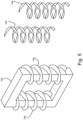
- FIG. 5 illustrates details of a helicoidal guide according to embodiments of the present disclosure.
- the helicoidal guide may be adapted to have an inlet configured to improve utilization of a fan.
- the helicoidal guide may be engrooved inside the first coil and/or attached to the first coil.
- the helicoidal guide may be part of the core (e.g. employing sintering, grooving) or attached to the core.
- the helicoidal guide may be part of and/or attached to the coil (helical groove).
- the helicoidal guide may be part of and/or attached to the core.
- the helicoidal structure may be manufactured as air guidance component, to be mounted during the assembly of the MFT.
- the helicoidal guide may be inserted in the spatial gap between first coil and core during the MFT assembly.
- Mounting structures may be optionally attached to the first coil and/or the core to keep the helicoidal guide in place and/or in shape.
- the helicoidal guide may be adapted to cores with legs with circular cross sections and/or rectangular cross sections.
- the helicoidal guide nay be adapted to coils with circular shape and/or rectangular shape.
- the helicoidal guides may be adapted as to allow a flow of coolant along the helicoidal shape of the guide, without coolant bypassing the turns of the helicoidal guides.
- the transformers of the present disclosure may be oil transformers and/or three-phase transformers.
- FIG. 5 illustrates that the helical guide 140 may extend around different legs of the core 120, in particular when the coils are split into parts wound around different legs and/or in the presence of three-phase transformers.
- Two legs are exemplarily shown, but the number of legs and the geometry of the core may be any known geometry/arrangement for a transformer.
- the helicoidal guide may for example have a pitch of at least 2 cm and/or of at most 50 cm.
- the helicoidal guide may for example include two or more turns.
- the pitch and/or the total length of the helicoidal guide may be adjusted to optimize a cooling performance of a fan.
- the pitch of the helicoidal guide may be adjusted in function of a pressure difference of the coolant flowing along the helicoidal guide and/or to increase a flow rate of the coolant flowing along the helicoidal guide and/or to maximize the heat transfer from the first coil and/or from the core to the coolant (for example air) and/or to maximize said heat transfer divided by a power consumption of the fan.
- the shape of the helicoidal guide may therefore result from a nonlinear optimization problem taking into account the cooling performance of the coolant and the required power for the fan, to obtain a maximum of cooling with or without constraints on the power consumption of the fan.
- the optimization problem may further take into account a noise level produced by the fan, for example as a constraint to keep the noise produced by the fan below a threshold.
- the helicoidal guide may be made of epoxy and/or metal and be designed as to avoid or minimize Eddy currents in the guide.
- the present disclosure provides a helicoidal guide configured and shaped for cooling an inductor and/or a transformer with a core and a first coil having a spatial gap between the core and the first coil, the helicoidal guide being placeable within the spatial gap and configured to guide a flow of coolant through the spatial gap, wherein the coolant is in direct contact with the first coil and optionally with the core.
- the transformer may be a medium frequency transformer, in particular a medium frequency transformer part of one or more stacked arrangements of a plurality of medium frequency transformers, for example in particular part of a solid state transformer.
- the helicoidal guide has at least two turns; and/or has a pitch of at least 2 cm and/or a pitch of at most 50 cm;
- the present disclosure further provides an inductor comprising
- the inductor further comprises a fan to produce a flow of a coolant guided by the helicoidal guide in the spatial gap.
- the coolant is air.
- the helicoidal guide is attached to the inductor core and/or the helicoidal guide is attached to the first coil of the inductor.
- the helicoidal guide and the inductor core form a single piece.
- the inductor core partially obstructs the spatial gap partially hindering an inflow and/or an outflow of coolant into and/or out of the spatial gap
- the helicoidal guide is configured to produce a uniform flow of the coolant around the inductor core in the spatial gap when coolant flows in the spatial gap.
- said uniform flow may be obtained optimizing the form and/or geometry of the helicoidal guide, to obtain at least an improvement in the cooling by the flow of coolant.
- the core may be a ferrite core and the helicoidal guide may be engraved in the ferrite core.
- the present disclosure further provides, a transformer comprising
- the first coil may be at a low potential, although the coil does not need to be grounded.
- the second coil may be at a medium voltage.
- the transformer further comprises electrically insulating oil to insulate the first coil from the second coil and/or the transformer is a three-phase transformer.
- the second coil is wound around the first coil of the transformer, in particular the second coil of the transformer forms a high voltage coil and the first coil of the transformer forms a low voltage coil, the high voltage being greater than the low voltage.
- the second coil may for example be at high voltage and the first coil at low voltage.
- a low voltage of the first coil is related to a low voltage insulation of the first coil.
- the voltage across the terminals of the first coil may be any convenient voltage.
- the transformer further comprises a mounting structure attached to the transformer core and/or to the first coil and/or to the second coil configured to hold the helicoidal guide in place within the spatial gap.
- producing a flow is obtained using a fan and the coolant is air.
Landscapes
- Engineering & Computer Science (AREA)
- Power Engineering (AREA)
- Coils Of Transformers For General Uses (AREA)
Claims (17)
- Spiralförmige Führung (140), die so konfiguriert und geformt ist, dass sie einen Induktor und/oder einen Transformator mit einem Kern (120) und einer ersten Spule (110) mit einem räumlichen Spalt (130) zwischen dem Kern (120) und der ersten Spule (110) kühlt, wobei die spiralförmige Führung in dem räumlichen Spalt platziert werden kann und so konfiguriert ist, dass sie eine Kühlmittelströmung durch den räumlichen Spalt leitet, dadurch gekennzeichnet, dass das Kühlmittel in direktem Kontakt mit der ersten Spule steht.
- Spiralförmige Führung nach Anspruch 1, wobei das Kühlmittel in direktem Kontakt mit dem Kern steht.
- Spiralförmige Führung nach Anspruch 1 oder Anspruch 2 mit mindestens zwei Windungen;
und/oder mit einem Abstand von mindestens 2 cm und/oder einem Abstand von höchstens 50 cm. - Induktor, umfassendeinen Induktorkern,wobei eine erste Spule des Induktors durch eine elektrisch isolierte Wicklung gebildet wird, die um den Induktorkern gewickelt ist,eine spiralförmige Führung nach einem der Ansprüche 1 bis 3;wobei ein räumlicher Spalt zwischen dem Induktorkern und der ersten Spule des Induktors vorhanden ist, wobei die spiralförmige Führung in dem räumlichen Spalt platziert ist;und wobei die spiralförmige Führung so konfiguriert ist, dass sie ein Kühlmittel in dem räumlichen Spalt führt, wobei das Kühlmittel in direktem Kontakt mit der ersten Spule (110) des Induktors und wahlweise mit dem Induktorkern (120) steht.
- Induktor nach Anspruch 4, ferner umfassend ein Gebläse zur Erzeugung einer Kühlmittelströmung, die durch die spiralförmige Führung in dem räumlichen Spalt geführt wird.
- Induktor nach einem der Ansprüche 4 und 5, wobei es sich bei dem Kühlmittel um Luft handelt.
- Induktor nach einem der Ansprüche 4 bis 6, wobei die spiralförmige Führung am Induktorkern angebracht ist und/oder wobei die spiralförmige Führung an der ersten Spule des Induktors angebracht ist.
- Induktor nach einem der Ansprüche 4 bis 7, wobei die spiralförmige Führung und der Induktorkern ein einziges Stück bilden.
- Induktor nach einem der Ansprüche 4 bis 8, wobei der Induktorkern den räumlichen Spalt teilweise versperrt und ein Einströmen und/oder Ausströmen von Kühlmittel in den und/oder aus dem räumlichen Spalt teilweise behindert, und wobei die spiralförmige Führung so konfiguriert ist, dass sie eine gleichmäßige Strömung des Kühlmittels um den Induktorkern im räumlichen Spalt erzeugt, wenn Kühlmittel im räumlichen Spalt strömt.
- Induktor nach einem der Ansprüche 4 bis 9, wobei die spiralförmige Führung aus isolierendem Epoxidharz oder aus einem leitenden Material besteht, das dasselbe Material wie der Induktorkern ist, und/oder wobei die spiralförmige Führung aus elektrisch isolierten Segmenten gebildet ist und/oder die spiralförmige Führung in den Kern eingraviert ist.
- Transformator, umfassendeinen Induktor nach einem der Ansprüche 4 bis 10, wobei der Induktorkern einen Transformatorkern (120) bildet und die erste Spule (110) des Induktors eine erste Spule des Transformators bildet;eine zweite Spule (112) des Transformators, die durch eine gegenüber der ersten Spule isolierte Wicklung gebildet ist,wobei ein räumlicher Spalt zwischen dem Transformatorkern und der ersten Spule des Transformators vorhanden ist, wobei die spiralförmige Führung in dem räumlichen Spalt platziert ist;und wobei die spiralförmige Führung so konfiguriert ist, dass sie ein Kühlmittel in dem räumlichen Spalt führt, das die erste Spule des Transformators und/oder den Transformatorkern kühlt, wobei das Kühlmittel in direktem Kontakt mit der ersten Spule (110) des Transformators und wahlweise mit dem Transformatorkern (120) steht.
- Transformator nach Anspruch 11, ferner umfassend elektrisch isolierendes Öl, um die erste Spule gegenüber der zweiten Spule zu isolieren und/oder wobei es sich bei dem Transformator um einen Dreiphasentransformator handelt.
- Transformator nach einem der Ansprüche 11 und 12, wobei die zweite Spule um die erste Spule des Transformators gewickelt ist, wobei insbesondere die zweite Spule des Transformators eine Hochspannungsspule bildet und die erste Spule des Transformators eine Niederspannungsspule bildet, wobei die Hochspannung größer ist als die Niederspannung.
- Transformator nach einem der Ansprüche 11 bis 13, ferner umfassend eine am Transformatorkern und/oder an der ersten Spule und/oder an der zweiten Spule angebrachte Befestigungsstruktur, die so konfiguriert ist, dass sie die spiralförmige Führung in dem räumlichen Spalt fixiert.
- Transformator nach einem der Ansprüche 11 bis 14, wobei der Transformatorkern einen kreisförmigen Querschnitt oder einen rechteckigen Querschnitt aufweist und die erste Spule und die zweite Spule eine Kreisform oder eine Rechteckform aufweisen; und wobei die spiralförmige Führung an den Querschnitt des Kerns und die Form der Spulen angepasst ist.
- Verfahren zum Kühlen eines Transformators, insbesondere des Transformators nach einem der Ansprüche 11 bis 15, oder eines Induktors, insbesondere des Induktors nach einem der Ansprüche 4 bis 10, mit einem Kern und mit einer ersten Spule, die durch eine elektrisch isolierte Wicklung gebildet wird, die um den Kern gewickelt ist, wobei der Transformator oder der Induktor einen räumlichen Spalt zwischen dem Kern und der ersten Spule aufweist, wobei das Verfahren umfasst:Bereitstellen einer spiralförmigen Führung innerhalb des räumlichen Spalts,Erzeugen einer Strömung eines Kühlmittels in den räumlichen Spalt;wobei die spiralförmige Führung so konfiguriert ist, dass sie das Kühlmittel in den räumlichen Spalt führt und einen direkten Kontakt zwischen dem Kühlmittel und der ersten Spule und wahlweise zwischen dem Kühlmittel und dem Kern herstellt.
- Verfahren nach Anspruch 16, wobei das Erzeugen einer Strömung unter Verwendung eines Gebläses erfolgt und es sich bei dem Kühlmittel um Luft handelt.
Priority Applications (4)
| Application Number | Priority Date | Filing Date | Title |
|---|---|---|---|
| EP21177404.7A EP4099346B1 (de) | 2021-06-02 | 2021-06-02 | Schraubenförmige führung zur kühlung eines mittelfrequenztransformators |
| CN202280039002.4A CN117480578A (zh) | 2021-06-02 | 2022-06-01 | 用于中频变压器的冷却的螺旋引导件 |
| PCT/EP2022/064956 WO2022253916A1 (en) | 2021-06-02 | 2022-06-01 | Helicoidal guide for the cooling of a medium-frequency transformer |
| US18/566,355 US20250054675A1 (en) | 2021-06-02 | 2022-06-01 | Helicoidal guide for the cooling of a medium-frequency transformer |
Applications Claiming Priority (1)
| Application Number | Priority Date | Filing Date | Title |
|---|---|---|---|
| EP21177404.7A EP4099346B1 (de) | 2021-06-02 | 2021-06-02 | Schraubenförmige führung zur kühlung eines mittelfrequenztransformators |
Publications (3)
| Publication Number | Publication Date |
|---|---|
| EP4099346A1 EP4099346A1 (de) | 2022-12-07 |
| EP4099346B1 true EP4099346B1 (de) | 2024-08-21 |
| EP4099346C0 EP4099346C0 (de) | 2024-08-21 |
Family
ID=76250210
Family Applications (1)
| Application Number | Title | Priority Date | Filing Date |
|---|---|---|---|
| EP21177404.7A Active EP4099346B1 (de) | 2021-06-02 | 2021-06-02 | Schraubenförmige führung zur kühlung eines mittelfrequenztransformators |
Country Status (4)
| Country | Link |
|---|---|
| US (1) | US20250054675A1 (de) |
| EP (1) | EP4099346B1 (de) |
| CN (1) | CN117480578A (de) |
| WO (1) | WO2022253916A1 (de) |
Families Citing this family (1)
| Publication number | Priority date | Publication date | Assignee | Title |
|---|---|---|---|---|
| CN118675853B (zh) * | 2024-07-18 | 2024-11-26 | 东亮电气有限公司 | 一种光伏固态变压器 |
Family Cites Families (4)
| Publication number | Priority date | Publication date | Assignee | Title |
|---|---|---|---|---|
| US7205875B2 (en) * | 2003-06-26 | 2007-04-17 | Eaton Power Quality Corporation | Hybrid air/magnetic core inductor |
| CN205148832U (zh) * | 2015-11-27 | 2016-04-13 | 宁波君灵模具技术有限公司 | 一种超厚型芯螺旋冷却装置 |
| EP3373314A1 (de) * | 2017-03-10 | 2018-09-12 | ABB Schweiz AG | Kühlung von nicht-flüssigen eingetauchten transformatoren |
| CN213277725U (zh) * | 2020-11-24 | 2021-05-25 | 惠州市磁极新能源科技有限公司 | 实芯电感线圈 |
-
2021
- 2021-06-02 EP EP21177404.7A patent/EP4099346B1/de active Active
-
2022
- 2022-06-01 WO PCT/EP2022/064956 patent/WO2022253916A1/en not_active Ceased
- 2022-06-01 CN CN202280039002.4A patent/CN117480578A/zh active Pending
- 2022-06-01 US US18/566,355 patent/US20250054675A1/en active Pending
Also Published As
| Publication number | Publication date |
|---|---|
| CN117480578A (zh) | 2024-01-30 |
| EP4099346A1 (de) | 2022-12-07 |
| WO2022253916A1 (en) | 2022-12-08 |
| EP4099346C0 (de) | 2024-08-21 |
| US20250054675A1 (en) | 2025-02-13 |
Similar Documents
| Publication | Publication Date | Title |
|---|---|---|
| JP6400663B2 (ja) | 非接触給電トランス | |
| EP2671234B1 (de) | Trockenverteilertransformator | |
| EP2444983A2 (de) | Flüssiges, gekühltes magnetisches Bauteil mit indirekter Kühlung für Hochfrequenz- und Hochleistungsanwendungen | |
| US20150109090A1 (en) | Electrical transformer with a shielded cast coil assembly | |
| JP6317244B2 (ja) | 誘導加熱用コイルユニットおよび誘導加熱装置 | |
| US20150109081A1 (en) | Cast coil assembly with fins for an electrical transformer | |
| US20230395313A1 (en) | Heat transfer from transformer windings | |
| EP4099346B1 (de) | Schraubenförmige führung zur kühlung eines mittelfrequenztransformators | |
| CN104205259B (zh) | 用于电动车辆的变压器 | |
| KR101088171B1 (ko) | 냉각 파이프를 구비하는 주상변압기 | |
| EP3657518B1 (de) | Elektromagnetische vorrichtung mit thermisch wärmeleitendem former | |
| EP3062319B1 (de) | Transformator zur reduzierung von wirbelstromverlusten einer spule | |
| WO2020036507A1 (ru) | Сглаживающе-токоограничивающий реактор фильтр-устройства железнодорожной тяговой подстанции | |
| Dawood et al. | Cost analysis and economic factors in transformer design and production | |
| CN115481555B (zh) | 大功率高频磁谐振空心变压器优化设计方法 | |
| Liu et al. | Effects of axial gap length between disc windings on magnetic fields and power losses of evaporative cooling traction transformers | |
| CN110729103B (zh) | 一种隔离变压器 | |
| Chen et al. | Design method for high-power high-frequency magnetic-resonance air-core transformer | |
| US20230008213A1 (en) | Electrotechnical device for an aircraft, comprising low-frequency coil components | |
| US20230033439A1 (en) | Electrotechnical device for an aircraft | |
| AU738507B2 (en) | Inductance arrangement | |
| CN217719270U (zh) | 变压器 | |
| KR102555275B1 (ko) | 변압장치용 철심구조 | |
| US11942254B2 (en) | Transformer insulation modification | |
| KR200486562Y1 (ko) | 자속차폐판을 구비한 유입변압기 |
Legal Events
| Date | Code | Title | Description |
|---|---|---|---|
| PUAI | Public reference made under article 153(3) epc to a published international application that has entered the european phase |
Free format text: ORIGINAL CODE: 0009012 |
|
| STAA | Information on the status of an ep patent application or granted ep patent |
Free format text: STATUS: THE APPLICATION HAS BEEN PUBLISHED |
|
| AK | Designated contracting states |
Kind code of ref document: A1 Designated state(s): AL AT BE BG CH CY CZ DE DK EE ES FI FR GB GR HR HU IE IS IT LI LT LU LV MC MK MT NL NO PL PT RO RS SE SI SK SM TR |
|
| STAA | Information on the status of an ep patent application or granted ep patent |
Free format text: STATUS: REQUEST FOR EXAMINATION WAS MADE |
|
| 17P | Request for examination filed |
Effective date: 20230606 |
|
| RBV | Designated contracting states (corrected) |
Designated state(s): AL AT BE BG CH CY CZ DE DK EE ES FI FR GB GR HR HU IE IS IT LI LT LU LV MC MK MT NL NO PL PT RO RS SE SI SK SM TR |
|
| GRAP | Despatch of communication of intention to grant a patent |
Free format text: ORIGINAL CODE: EPIDOSNIGR1 |
|
| STAA | Information on the status of an ep patent application or granted ep patent |
Free format text: STATUS: GRANT OF PATENT IS INTENDED |
|
| RIC1 | Information provided on ipc code assigned before grant |
Ipc: H01F 27/12 20060101ALN20240307BHEP Ipc: H01F 27/08 20060101AFI20240307BHEP |
|
| INTG | Intention to grant announced |
Effective date: 20240327 |
|
| GRAS | Grant fee paid |
Free format text: ORIGINAL CODE: EPIDOSNIGR3 |
|
| GRAA | (expected) grant |
Free format text: ORIGINAL CODE: 0009210 |
|
| STAA | Information on the status of an ep patent application or granted ep patent |
Free format text: STATUS: THE PATENT HAS BEEN GRANTED |
|
| AK | Designated contracting states |
Kind code of ref document: B1 Designated state(s): AL AT BE BG CH CY CZ DE DK EE ES FI FR GB GR HR HU IE IS IT LI LT LU LV MC MK MT NL NO PL PT RO RS SE SI SK SM TR |
|
| REG | Reference to a national code |
Ref country code: GB Ref legal event code: FG4D |
|
| REG | Reference to a national code |
Ref country code: CH Ref legal event code: EP |
|
| REG | Reference to a national code |
Ref country code: IE Ref legal event code: FG4D |
|
| REG | Reference to a national code |
Ref country code: DE Ref legal event code: R096 Ref document number: 602021017410 Country of ref document: DE |
|
| U01 | Request for unitary effect filed |
Effective date: 20240904 |
|
| U07 | Unitary effect registered |
Designated state(s): AT BE BG DE DK EE FI FR IT LT LU LV MT NL PT RO SE SI Effective date: 20240923 |
|
| PG25 | Lapsed in a contracting state [announced via postgrant information from national office to epo] |
Ref country code: NO Free format text: LAPSE BECAUSE OF FAILURE TO SUBMIT A TRANSLATION OF THE DESCRIPTION OR TO PAY THE FEE WITHIN THE PRESCRIBED TIME-LIMIT Effective date: 20241121 |
|
| PG25 | Lapsed in a contracting state [announced via postgrant information from national office to epo] |
Ref country code: GR Free format text: LAPSE BECAUSE OF FAILURE TO SUBMIT A TRANSLATION OF THE DESCRIPTION OR TO PAY THE FEE WITHIN THE PRESCRIBED TIME-LIMIT Effective date: 20241122 Ref country code: PL Free format text: LAPSE BECAUSE OF FAILURE TO SUBMIT A TRANSLATION OF THE DESCRIPTION OR TO PAY THE FEE WITHIN THE PRESCRIBED TIME-LIMIT Effective date: 20240821 |
|
| PG25 | Lapsed in a contracting state [announced via postgrant information from national office to epo] |
Ref country code: IS Free format text: LAPSE BECAUSE OF FAILURE TO SUBMIT A TRANSLATION OF THE DESCRIPTION OR TO PAY THE FEE WITHIN THE PRESCRIBED TIME-LIMIT Effective date: 20241221 |
|
| PG25 | Lapsed in a contracting state [announced via postgrant information from national office to epo] |
Ref country code: HR Free format text: LAPSE BECAUSE OF FAILURE TO SUBMIT A TRANSLATION OF THE DESCRIPTION OR TO PAY THE FEE WITHIN THE PRESCRIBED TIME-LIMIT Effective date: 20240821 |
|
| PG25 | Lapsed in a contracting state [announced via postgrant information from national office to epo] |
Ref country code: ES Free format text: LAPSE BECAUSE OF FAILURE TO SUBMIT A TRANSLATION OF THE DESCRIPTION OR TO PAY THE FEE WITHIN THE PRESCRIBED TIME-LIMIT Effective date: 20240821 Ref country code: RS Free format text: LAPSE BECAUSE OF FAILURE TO SUBMIT A TRANSLATION OF THE DESCRIPTION OR TO PAY THE FEE WITHIN THE PRESCRIBED TIME-LIMIT Effective date: 20241121 |
|
| PG25 | Lapsed in a contracting state [announced via postgrant information from national office to epo] |
Ref country code: RS Free format text: LAPSE BECAUSE OF FAILURE TO SUBMIT A TRANSLATION OF THE DESCRIPTION OR TO PAY THE FEE WITHIN THE PRESCRIBED TIME-LIMIT Effective date: 20241121 Ref country code: PL Free format text: LAPSE BECAUSE OF FAILURE TO SUBMIT A TRANSLATION OF THE DESCRIPTION OR TO PAY THE FEE WITHIN THE PRESCRIBED TIME-LIMIT Effective date: 20240821 Ref country code: NO Free format text: LAPSE BECAUSE OF FAILURE TO SUBMIT A TRANSLATION OF THE DESCRIPTION OR TO PAY THE FEE WITHIN THE PRESCRIBED TIME-LIMIT Effective date: 20241121 Ref country code: IS Free format text: LAPSE BECAUSE OF FAILURE TO SUBMIT A TRANSLATION OF THE DESCRIPTION OR TO PAY THE FEE WITHIN THE PRESCRIBED TIME-LIMIT Effective date: 20241221 Ref country code: HR Free format text: LAPSE BECAUSE OF FAILURE TO SUBMIT A TRANSLATION OF THE DESCRIPTION OR TO PAY THE FEE WITHIN THE PRESCRIBED TIME-LIMIT Effective date: 20240821 Ref country code: GR Free format text: LAPSE BECAUSE OF FAILURE TO SUBMIT A TRANSLATION OF THE DESCRIPTION OR TO PAY THE FEE WITHIN THE PRESCRIBED TIME-LIMIT Effective date: 20241122 Ref country code: ES Free format text: LAPSE BECAUSE OF FAILURE TO SUBMIT A TRANSLATION OF THE DESCRIPTION OR TO PAY THE FEE WITHIN THE PRESCRIBED TIME-LIMIT Effective date: 20240821 |
|
| PG25 | Lapsed in a contracting state [announced via postgrant information from national office to epo] |
Ref country code: SM Free format text: LAPSE BECAUSE OF FAILURE TO SUBMIT A TRANSLATION OF THE DESCRIPTION OR TO PAY THE FEE WITHIN THE PRESCRIBED TIME-LIMIT Effective date: 20240821 |
|
| PG25 | Lapsed in a contracting state [announced via postgrant information from national office to epo] |
Ref country code: CZ Free format text: LAPSE BECAUSE OF FAILURE TO SUBMIT A TRANSLATION OF THE DESCRIPTION OR TO PAY THE FEE WITHIN THE PRESCRIBED TIME-LIMIT Effective date: 20240821 |
|
| PG25 | Lapsed in a contracting state [announced via postgrant information from national office to epo] |
Ref country code: SK Free format text: LAPSE BECAUSE OF FAILURE TO SUBMIT A TRANSLATION OF THE DESCRIPTION OR TO PAY THE FEE WITHIN THE PRESCRIBED TIME-LIMIT Effective date: 20240821 |
|
| PLBE | No opposition filed within time limit |
Free format text: ORIGINAL CODE: 0009261 |
|
| STAA | Information on the status of an ep patent application or granted ep patent |
Free format text: STATUS: NO OPPOSITION FILED WITHIN TIME LIMIT |
|
| 26N | No opposition filed |
Effective date: 20250522 |
|
| U20 | Renewal fee for the european patent with unitary effect paid |
Year of fee payment: 5 Effective date: 20250627 |
|
| REG | Reference to a national code |
Ref country code: CH Ref legal event code: H13 Free format text: ST27 STATUS EVENT CODE: U-0-0-H10-H13 (AS PROVIDED BY THE NATIONAL OFFICE) Effective date: 20260127 |
|
| PG25 | Lapsed in a contracting state [announced via postgrant information from national office to epo] |
Ref country code: MC Free format text: LAPSE BECAUSE OF FAILURE TO SUBMIT A TRANSLATION OF THE DESCRIPTION OR TO PAY THE FEE WITHIN THE PRESCRIBED TIME-LIMIT Effective date: 20240821 |
|
| GBPC | Gb: european patent ceased through non-payment of renewal fee |
Effective date: 20250602 |
|
| PG25 | Lapsed in a contracting state [announced via postgrant information from national office to epo] |
Ref country code: GB Free format text: LAPSE BECAUSE OF NON-PAYMENT OF DUE FEES Effective date: 20250602 |
|
| PG25 | Lapsed in a contracting state [announced via postgrant information from national office to epo] |
Ref country code: IE Free format text: LAPSE BECAUSE OF NON-PAYMENT OF DUE FEES Effective date: 20250602 |