EP4099531B1 - Procédé de détermination des paramètres réseau destiné à la commande d'une bobine de petersen - Google Patents
Procédé de détermination des paramètres réseau destiné à la commande d'une bobine de petersen Download PDFInfo
- Publication number
- EP4099531B1 EP4099531B1 EP22168172.9A EP22168172A EP4099531B1 EP 4099531 B1 EP4099531 B1 EP 4099531B1 EP 22168172 A EP22168172 A EP 22168172A EP 4099531 B1 EP4099531 B1 EP 4099531B1
- Authority
- EP
- European Patent Office
- Prior art keywords
- zero
- sequence voltage
- angular velocity
- zero voltage
- pointer
- Prior art date
- Legal status (The legal status is an assumption and is not a legal conclusion. Google has not performed a legal analysis and makes no representation as to the accuracy of the status listed.)
- Active
Links
Images


Classifications
-
- H—ELECTRICITY
- H02—GENERATION; CONVERSION OR DISTRIBUTION OF ELECTRIC POWER
- H02H—EMERGENCY PROTECTIVE CIRCUIT ARRANGEMENTS
- H02H9/00—Emergency protective circuit arrangements for limiting excess current or voltage without disconnection
- H02H9/08—Limitation or suppression of earth fault currents, e.g. Petersen coil
-
- G—PHYSICS
- G01—MEASURING; TESTING
- G01R—MEASURING ELECTRIC VARIABLES; MEASURING MAGNETIC VARIABLES
- G01R27/00—Arrangements for measuring resistance, reactance, impedance, or electric characteristics derived therefrom
- G01R27/02—Measuring real or complex resistance, reactance, impedance, or other two-pole characteristics derived therefrom, e.g. time constant
- G01R27/16—Measuring impedance of element or network through which a current is passing from another source, e.g. cable, power line
-
- H—ELECTRICITY
- H02—GENERATION; CONVERSION OR DISTRIBUTION OF ELECTRIC POWER
- H02H—EMERGENCY PROTECTIVE CIRCUIT ARRANGEMENTS
- H02H3/00—Emergency protective circuit arrangements for automatic disconnection directly responsive to an undesired change from normal electric working condition with or without subsequent reconnection ; integrated protection
- H02H3/16—Emergency protective circuit arrangements for automatic disconnection directly responsive to an undesired change from normal electric working condition with or without subsequent reconnection ; integrated protection responsive to fault current to earth, frame or mass
- H02H3/162—Emergency protective circuit arrangements for automatic disconnection directly responsive to an undesired change from normal electric working condition with or without subsequent reconnection ; integrated protection responsive to fault current to earth, frame or mass for AC systems
- H02H3/165—Emergency protective circuit arrangements for automatic disconnection directly responsive to an undesired change from normal electric working condition with or without subsequent reconnection ; integrated protection responsive to fault current to earth, frame or mass for AC systems for three-phase systems
-
- H—ELECTRICITY
- H02—GENERATION; CONVERSION OR DISTRIBUTION OF ELECTRIC POWER
- H02J—ELECTRIC POWER NETWORKS; CIRCUIT ARRANGEMENTS OR SYSTEMS FOR SUPPLYING OR DISTRIBUTING ELECTRIC POWER; SYSTEMS FOR STORING ELECTRIC ENERGY
- H02J3/00—Circuit arrangements for AC mains or AC distribution networks
- H02J3/18—Arrangements for adjusting, eliminating or compensating reactive power in networks
Definitions
- the invention relates to a method for determining network parameters for controlling a Petersen coil for earth fault compensation of a multi-phase power network with a nominal frequency, wherein a zero voltage signal is detected.
- the control of the Petersen coil is a preventive measure in the event of a ground fault and should be carried out in a healthy network condition.
- the increase in the interconnection of power grids and increasingly frequent redispatching make frequent readjustments necessary.
- the AT504506B1 proposes that after an automatically extinguishing ground fault, the zero voltage is recorded during a time interval at the beginning of the decay process and a number of instantaneous frequency values are determined from the time between the zero crossings of the zero voltage and the frequency of the decay process is extrapolated from this.
- the disadvantage of the prior art is, on the one hand, that the tuning can only be determined after a ground fault and can no longer be used if a natural asymmetry occurs, since the zero crossings associated with the decay process can naturally no longer be determined.
- the WO2016029890A1 proposes to modulate an auxiliary signal with a variable frequency to a zero sequence component in a power grid without a ground fault and to carry out a frequency analysis for the resulting resonant circuit.
- the natural frequency at which the lowest current flows is then determined.
- This natural frequency is compared to the rated frequency of the electrical system to determine whether the resonant circuit is over- or under-compensated, whereupon the inductance of the Petersen coil is adjusted accordingly.
- the invention is therefore based on the object of providing a method for determining network parameters for earth fault compensation, in which the network parameters for a Petersen coil can be reliably determined within a period of the network frequency even if natural asymmetry occurs.
- the invention which is defined by method claim 1, solves the problem in that the continuous zero voltage signal is sampled during a transient decay process over a period of the nominal frequency and is transformed into the complex image area as a zero voltage pointer for each time step, after which For each time step, a synchronous zero voltage pointer is formed by reducing the angular velocity of the zero voltage pointer by a reference angular velocity and for each time step the vectorial difference between two synchronous zero voltage pointers with a predetermined time interval is determined, after which the angular deviation between the vectorial differences of two time steps as the angular velocity deviation of the zero voltage pointer from the reference angular velocity and/or the absolute value deviation of the vectorial differences between two time steps is output as attenuation of the zero voltage vector.
- a transient decay process can be caused, for example, by an initial or re-igniting ground fault in a phase, or by feeding in a modulation current.
- the sampling of the zero voltage signal is preferably carried out at an integer multiple of the nominal frequency of the power network and can be carried out, for example, via an analog-digital converter, which forwards the sampled values to a computing unit.
- This computing unit transforms the zero voltage signal into the complex image area based on the sample values.
- the pointers formed for each time step are referred to as zero voltage pointers.
- the angular velocity of the zero voltage vectors is then reduced by a reference angular velocity to form synchronous zero voltage vectors. This reference angular velocity can, for example, be the angular velocity corresponding to the nominal frequency.
- the concatenated voltage signal between two conductors is sampled, also transformed, and its angular velocity is used as the reference angular velocity.
- the reduced angular velocity of the synchronous zero voltage pointer facilitates the subsequent determination of the network parameters from the rate of change of the magnitude and angle of the vectorial difference between two synchronous zero voltage pointers with a predetermined time interval. This time interval can be fixed. However, since the frequency and consequently the angular velocity of the zero voltage can differ from the nominal frequency, the transformation into the complex Leakage effects occur in the image area, which manifest themselves in local minima and maxima of the magnitude of the zero voltage vector and subsequently in the magnitude and angle of the synchronous zero voltage vector.
- These disturbances resulting from the transformation into the complex image area can either be compensated for using a correction factor to be determined, or the time interval between two synchronous zero voltage vectors, which are used to determine the vectorial difference, is selected so that the synchronous zero voltage vectors used have local minima or Maxima of the magnitude of the synchronous zero voltage pointer coincide. In the latter case, the time interval corresponds to the time interval between two minima or maxima of the magnitude of the synchronous zero voltage vector.
- U N and U ab are the amplitudes of the nominal voltage component or the decaying voltage
- ⁇ N and ⁇ ab are the angular velocity of the nominal voltage component or the decaying component
- t is the time and j is the imaginary unit.
- ⁇ is the (real) time constant of the decay process
- ⁇ is the difference between ⁇ ab and ⁇ N and ⁇ 0 is the phase shift.
- the invention is based on the knowledge that in the event of a transient decay process, the synchronous zero voltage vectors form a logarithmic spiral in the complex image plane, so that the angular velocity of the synchronous zero voltage vectors as well as the logarithmic damping of the magnitude of the synchronous zero voltage vectors are largely constant during the decay process.
- the angular velocity of the vectorial difference between two synchronous zero voltage vectors and the rate of change of the attenuation of the vectorial difference between two synchronous zero voltage vectors are largely constant during the decay process and allow conclusions to be drawn about the rates of change of the angular velocity and the magnitude of the synchronous zero voltage vector and thus also of the zero voltage vector itself.
- the network parameters for controlling the Petersen coil can be reliably determined by averaging within a network period, in particular within half a network period, after a multiple of the specified time intervals, provided that the significant interference influences on the transformation in the complex image area have subsided.
- the transformation into the complex image area can, for example, be a discrete Fourier transformation.
- the computing unit can transfer the deviation of the angle of the vectorial difference between two time steps as the angular velocity deviation of the zero voltage vector from the reference angular velocity and / or the absolute value deviation of the vectorial differences between two time steps as the damping of the zero voltage vector as a network parameter to a controller for the Petersen coil in order to control the parallel resonant circuit true that a capacitive ground fault current can be compensated.
- the resource expenditure for carrying out the method according to the invention on a computing unit can be reduced if, as described above, the predetermined time interval is the time interval between two minima or maxima of the magnitude of the synchronous zero voltage vector.
- an additional impedance can, for example, be connected between the star point of the power network and earth for a predetermined period of time. This period can be at least half a period of the nominal frequency.
- the star point can alternatively be connected to a voltage source via the additional impedance.
- the modulation current pulse can have different signal forms, such as an approximate Dirac pulse, an alternating signal with nominal frequency or an alternating signal with multiple and/or varying frequency components.
- the modulation current pulse can be fed into the zero system, for example, at the star point of the multi-phase power network, with feeding possible both in front of the Petersen coil and between the Petersen coil and the star point.
- the energy required to feed in the modulation current pulse can be considerable, so that, especially in power networks with natural asymmetry, it is advisable to short-circuit the star point to earth via a current-limiting impedance in order to apply a modulation current pulse to the zero system.
- the method according to the invention therefore has the advantage that external Petersen coils can also be taken into account, since these influence the zero voltage in the decay process and their switching on and off can therefore be recognized.
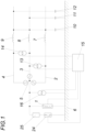
- the parameters for a Petersen coil 1 for a power network with three conductors 2, 3, 4 are determined.
- the Petersen coil 1 is connected between the star point 5 of the star connection of the three conductors 2, 3, 4 and the earth 6 to form a parallel resonant circuit made up of the Petersen coil 1 and the inductors 7, 8, 9 and the earth capacitances 10, 11 , 12 to form the conductors 2, 3, 4.
- the ohmic line resistances are not shown.
- Voltage converters 13, 14 allow the interlinked voltage between the individual phases 2, 3, 4 to be determined and can sample the interlinked voltage over a period of the nominal frequency and forward these sampled values to a computing unit 15.
- a voltage converter 16 is provided which detects and samples the zero voltage between the star point 5 and the earth 6 and directs the sampled zero voltage signal 17 to the computing unit 15.
- the zero voltage signal 17 shown is sampled over a period of the nominal frequency of the power network and transformed into the complex image area by the computing unit 15 as a zero voltage pointer U 0 in the decay process.
- the angular velocity of this zero voltage pointer U 0 is then reduced by a reference angular velocity ⁇ N and thereby the Synchronous zero voltage pointer U 0 S formed.
- This reference angular velocity ⁇ N can be derived either from the nominal frequency or from the frequency of the linked voltage signal between two phases 2, 3, 4.
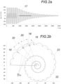
- the zero voltage signal 17 is sampled per time step, transformed into the complex image area as a zero voltage pointer U 0 and a synchronous zero voltage pointer U 0 S is formed therefrom.
- the vectorial difference 18 is then formed between the synchronous zero voltage pointer U 0 S of this time step and a synchronous zero voltage pointer U 0 S of a previous time step, preferably the immediately preceding time step.
- the computing unit 15 can temporarily store at least one synchronous zero voltage pointer U 0 S from a previous time step.
- the angular deviation 19 between the vector differences 18 of two time steps can then be determined and output as the angular velocity deviation ⁇ of the zero voltage pointer U 0 from the reference angular velocity ⁇ N.
- the magnitude deviation between the magnitudes 20 of the vector differences 18 of two time steps can also be determined and output as attenuation of the zero voltage vector U 0 and thus also of the synchronous voltage vector U 0 S.
- the time course of the logarithm of the amount 21 is for the in the Fig. 2b illustrated case in the Fig. 3a shown, where the slope of this curve corresponds to the attenuation.
- an angular deviation 19 and an amount deviation between the amounts 20 are determined for each time step, with vectorial differences 18 of two immediately successive time steps being used for the calculation. This means that only one must be in the computing unit 15 Synchronous zero voltage pointer U 0 S of the previous time step and a vector difference 18 of the previous time step are buffered, which enables extremely low resource consumption.
- the vector differences 18 approximately form a logarithmic spiral 22, the time course of the individual synchronous zero voltage pointers U 0 S being indicated by a connecting line 23.
- the angle of this synchronous zero voltage pointer U 0 S is for the in the Fig. 2b
- the slope of this curve corresponds to the angular velocity deviation and is ⁇ .
- Figs. 2a to 3b refer to the case without natural asymmetry
- the logarithmic spiral 22 is shifted away from the zero point.
- the measures according to the invention do not change the determination of the network parameters. By forming the vector differences 18, the asymmetrical signal component is eliminated.
- the zero system is subjected to a modulation current pulse, after which the zero voltage signal is sampled in the decay process to determine the zero voltage pointer U 0 and that The method according to the invention is carried out further as described above.
Landscapes
- Physics & Mathematics (AREA)
- General Physics & Mathematics (AREA)
- Inverter Devices (AREA)
- Ac-Ac Conversion (AREA)
- Testing Of Short-Circuits, Discontinuities, Leakage, Or Incorrect Line Connections (AREA)
- Control Of Eletrric Generators (AREA)
Claims (4)
- Procédé de détermination de paramètres de réseau pour le réglage d'une bobine de Petersen (1) pour compenser les défauts de terre d'un réseau électrique polyphasé doté d'une fréquence nominale, selon lequel un signal de tension nulle(17) est enregistré, ce signal de tension nulle continu (17) étant échantillonné lors d'un processus de relâchement transitoire sur une période de la fréquence nominale et chaque intervalle de temps étant transformé en vecteur de tension nulle U o dans la zone d'image complexe, caractérisé en ce qu'à chaque incrément de temps, un vecteur de tension nulle synchrone U os est formé en réduisant la vitesse angulaire du vecteur de tension nulle U o d'une vitesse angulaire de référence ω N et à chaque incrément de temps, la différence vectorielle (18) entre deux vecteurs de tension nulle synchrone U os est déterminée avec un écart temporel prédéfini, après quoi l'écart angulaire (19) entre les différences vectorielles (18) des deux incréments de temps est déduite comme étant l'écart de vitesse angulaire du vecteur de tension nulle U o par rapport à la vitesse angulaire de référence ω N et/ou l'écart quantitatif des différences vectorielles (18) des deux incréments de temps comme étant l'amortissement du vecteur de tension nulle U o.
- Procédé selon la revendication 1, caractérisé en ce que l'écart temporel prédéfini est l'écart temporel entre deux minima ou maxima de la quantité du vecteur de tension nulle synchrone U os.
- Procédé selon la revendication 1 ou 2, caractérisé en ce que le système homopolaire est soumis à une impulsion de courant de modulation, après quoi le signal de tension nulle (17) est échantillonné pendant le processus d'affaiblissement pour déterminer le vecteur de tension nulle U o.
- Procédé selon la revendication 3, caractérisé en ce que, pour soumettre le système homopolaire à une impulsion de courant de modulation, le point neutre (5) est mis en court-circuit avec la terre (6) par le biais d'une impédance limitant le courant (25).
Applications Claiming Priority (1)
| Application Number | Priority Date | Filing Date | Title |
|---|---|---|---|
| ATA50440/2021A AT524958B1 (de) | 2021-06-01 | 2021-06-01 | Verfahren zur Ermittlung von Netzparametern zur Regelung einer Petersen-Spule |
Publications (3)
| Publication Number | Publication Date |
|---|---|
| EP4099531A1 EP4099531A1 (fr) | 2022-12-07 |
| EP4099531C0 EP4099531C0 (fr) | 2023-12-13 |
| EP4099531B1 true EP4099531B1 (fr) | 2023-12-13 |
Family
ID=81260039
Family Applications (1)
| Application Number | Title | Priority Date | Filing Date |
|---|---|---|---|
| EP22168172.9A Active EP4099531B1 (fr) | 2021-06-01 | 2022-04-13 | Procédé de détermination des paramètres réseau destiné à la commande d'une bobine de petersen |
Country Status (2)
| Country | Link |
|---|---|
| EP (1) | EP4099531B1 (fr) |
| AT (1) | AT524958B1 (fr) |
Families Citing this family (1)
| Publication number | Priority date | Publication date | Assignee | Title |
|---|---|---|---|---|
| CN120628319B (zh) * | 2025-08-12 | 2025-10-10 | 温州卓业汽车科技有限公司 | 一种散热点火线圈的温度监测方法、系统及介质 |
Family Cites Families (8)
| Publication number | Priority date | Publication date | Assignee | Title |
|---|---|---|---|---|
| FR2697341B1 (fr) * | 1992-10-26 | 1995-01-13 | Electricite De France | Procédé et dispositif de mesure de l'accord et du désaccord de compensation d'un réseau de distribution électrique. |
| FI113592B (fi) * | 1997-08-27 | 2004-05-14 | Abb Oy | Menetelmä kompensointikuristimen säätämiseksi sähkönjakeluverkossa |
| DE10307668B3 (de) * | 2003-02-21 | 2005-01-13 | Edc Gmbh | Verfahren zur Bestimmung der Parameter eines gelöschten Netzes |
| DE502004001266D1 (de) * | 2004-05-18 | 2006-10-05 | Trench Austria Gmbh | Verfahren zum Anzeigen eines hochohmingen Erdschlusses in einem Drehstromnetz |
| AT504506B1 (de) | 2007-04-03 | 2008-06-15 | Univ Graz Tech | Verfahren zum nachstellen einer löschspule |
| CN101981774B (zh) * | 2008-04-03 | 2014-06-25 | 西门子公司 | 用于产生故障信号的方法、装置和现场设备 |
| CZ308721B6 (cs) | 2014-08-28 | 2021-03-24 | Ege, Spol.S R.O. | Způsob a zařízení pro automatické nastavení plynule a/nebo diskrétně laditelné zhášecí tlumivky v kompenzované síti elektrické soustavy |
| EP3657620B1 (fr) * | 2018-11-21 | 2021-08-18 | ABB Schweiz AG | Procédé et appareil de contrôle d'un dispositif de suppression d'arc |
-
2021
- 2021-06-01 AT ATA50440/2021A patent/AT524958B1/de active
-
2022
- 2022-04-13 EP EP22168172.9A patent/EP4099531B1/fr active Active
Also Published As
| Publication number | Publication date |
|---|---|
| EP4099531C0 (fr) | 2023-12-13 |
| AT524958B1 (de) | 2022-11-15 |
| EP4099531A1 (fr) | 2022-12-07 |
| AT524958A4 (de) | 2022-11-15 |
Similar Documents
| Publication | Publication Date | Title |
|---|---|---|
| EP3198698B1 (fr) | Procédé de protection de différentiel et appareil de protection de différentiel permettant de mettre en oeuvre un procédé de protection de différentiel | |
| EP2260556B1 (fr) | Procédé et dispositif de production d'un signal d'erreur | |
| DE2805524C2 (fr) | ||
| EP2449387B1 (fr) | Procédé et dispositif d'observation de l'état d'un réseau | |
| EP0993695B1 (fr) | Procede et systeme pour la detection de courts-circuits dans des reseaux basse tension | |
| CH665735A5 (de) | Verfahren zur ortung einer fehlerstelle in einer uebertragungsleitung. | |
| DE102011084910A1 (de) | Verfahren und Vorrichtung zum Einspeisen elektrischen Stroms in ein elektrisches Netz | |
| EP3046197A1 (fr) | Procédé et dispositif de détection de direction de défaut de mise à la terre dans un réseau à courant triphasé | |
| DE2609654A1 (de) | Digitaler ueberstromausloeser | |
| EP0150814B1 (fr) | Relais à impédance digital | |
| EP4099531B1 (fr) | Procédé de détermination des paramètres réseau destiné à la commande d'une bobine de petersen | |
| DE10302451B3 (de) | Verfahren zur Erkennung der Richtung eines Erdschlusses | |
| EP0812427B1 (fr) | Procede de reconnaissance de pertes monopolaires a la terre dans un reseau triphase | |
| DE69329326T2 (de) | Verfahren und Vorrichtung zum Messen der Anpassung und Fehlanpassung der Kompensation eines Stromversorgungsnetzes | |
| EP1844484B1 (fr) | Procede et dispositif pour determiner l'instant de commutation d'un appareil de commutation electrique | |
| DE102020114018A1 (de) | Verfahren und Vorrichtung zur Ermittlung der Richtung zu einem Erdschluss | |
| EP3916939A1 (fr) | Procédé pour une protection de conduites et agencement de protection | |
| DE4026799A1 (de) | Verfahren zur selektiven erfassung von fehlern der leiter in hoch- und hoechstspannungsnetzen | |
| DE10307668B3 (de) | Verfahren zur Bestimmung der Parameter eines gelöschten Netzes | |
| EP2908397B1 (fr) | Procédé de protection d'un réseau d'alimentation électrique | |
| EP3923435B1 (fr) | Procédé et dispositif de surveillance d'un réseau triphasé à fonctionnement compensé au niveau d'une variation de syntonisation de la bobine d'extinction | |
| DE10225058B4 (de) | Verfahren zur selektiven Erfassung von Erdschlusswischern in Drehstromnetzen | |
| EP3913382A1 (fr) | Procédé et dispositif de détermination de la localisation d'un défaut non symétrique à trois pôles sur une ligne d'un réseau d'alimentation électrique triphasé | |
| EP4310521B1 (fr) | Procédé et appareil de protection permettant de localiser une défaillance | |
| DE69731180T2 (de) | Verfahren und Gerät zur Erkennung von Kurzschlusszuständen |
Legal Events
| Date | Code | Title | Description |
|---|---|---|---|
| PUAI | Public reference made under article 153(3) epc to a published international application that has entered the european phase |
Free format text: ORIGINAL CODE: 0009012 |
|
| STAA | Information on the status of an ep patent application or granted ep patent |
Free format text: STATUS: THE APPLICATION HAS BEEN PUBLISHED |
|
| AK | Designated contracting states |
Kind code of ref document: A1 Designated state(s): AL AT BE BG CH CY CZ DE DK EE ES FI FR GB GR HR HU IE IS IT LI LT LU LV MC MK MT NL NO PL PT RO RS SE SI SK SM TR |
|
| STAA | Information on the status of an ep patent application or granted ep patent |
Free format text: STATUS: REQUEST FOR EXAMINATION WAS MADE |
|
| 17P | Request for examination filed |
Effective date: 20230502 |
|
| RBV | Designated contracting states (corrected) |
Designated state(s): AL AT BE BG CH CY CZ DE DK EE ES FI FR GB GR HR HU IE IS IT LI LT LU LV MC MK MT NL NO PL PT RO RS SE SI SK SM TR |
|
| GRAP | Despatch of communication of intention to grant a patent |
Free format text: ORIGINAL CODE: EPIDOSNIGR1 |
|
| STAA | Information on the status of an ep patent application or granted ep patent |
Free format text: STATUS: GRANT OF PATENT IS INTENDED |
|
| INTG | Intention to grant announced |
Effective date: 20231002 |
|
| GRAS | Grant fee paid |
Free format text: ORIGINAL CODE: EPIDOSNIGR3 |
|
| GRAA | (expected) grant |
Free format text: ORIGINAL CODE: 0009210 |
|
| STAA | Information on the status of an ep patent application or granted ep patent |
Free format text: STATUS: THE PATENT HAS BEEN GRANTED |
|
| AK | Designated contracting states |
Kind code of ref document: B1 Designated state(s): AL AT BE BG CH CY CZ DE DK EE ES FI FR GB GR HR HU IE IS IT LI LT LU LV MC MK MT NL NO PL PT RO RS SE SI SK SM TR |
|
| REG | Reference to a national code |
Ref country code: GB Ref legal event code: FG4D Free format text: NOT ENGLISH |
|
| REG | Reference to a national code |
Ref country code: CH Ref legal event code: EP |
|
| REG | Reference to a national code |
Ref country code: DE Ref legal event code: R096 Ref document number: 502022000320 Country of ref document: DE |
|
| REG | Reference to a national code |
Ref country code: IE Ref legal event code: FG4D Free format text: LANGUAGE OF EP DOCUMENT: GERMAN |
|
| U01 | Request for unitary effect filed |
Effective date: 20240108 |
|
| U07 | Unitary effect registered |
Designated state(s): AT BE BG DE DK EE FI FR IT LT LU LV MT NL PT SE SI Effective date: 20240117 |
|
| U1O | Appointed representative for the unitary patent procedure deleted after the registration of the unitary effect | ||
| PG25 | Lapsed in a contracting state [announced via postgrant information from national office to epo] |
Ref country code: GR Free format text: LAPSE BECAUSE OF FAILURE TO SUBMIT A TRANSLATION OF THE DESCRIPTION OR TO PAY THE FEE WITHIN THE PRESCRIBED TIME-LIMIT Effective date: 20240314 |
|
| PG25 | Lapsed in a contracting state [announced via postgrant information from national office to epo] |
Ref country code: ES Free format text: LAPSE BECAUSE OF FAILURE TO SUBMIT A TRANSLATION OF THE DESCRIPTION OR TO PAY THE FEE WITHIN THE PRESCRIBED TIME-LIMIT Effective date: 20231213 |
|
| PG25 | Lapsed in a contracting state [announced via postgrant information from national office to epo] |
Ref country code: GR Free format text: LAPSE BECAUSE OF FAILURE TO SUBMIT A TRANSLATION OF THE DESCRIPTION OR TO PAY THE FEE WITHIN THE PRESCRIBED TIME-LIMIT Effective date: 20240314 Ref country code: ES Free format text: LAPSE BECAUSE OF FAILURE TO SUBMIT A TRANSLATION OF THE DESCRIPTION OR TO PAY THE FEE WITHIN THE PRESCRIBED TIME-LIMIT Effective date: 20231213 |
|
| U20 | Renewal fee for the european patent with unitary effect paid |
Year of fee payment: 3 Effective date: 20240416 |
|
| PG25 | Lapsed in a contracting state [announced via postgrant information from national office to epo] |
Ref country code: RS Free format text: LAPSE BECAUSE OF FAILURE TO SUBMIT A TRANSLATION OF THE DESCRIPTION OR TO PAY THE FEE WITHIN THE PRESCRIBED TIME-LIMIT Effective date: 20231213 Ref country code: NO Free format text: LAPSE BECAUSE OF FAILURE TO SUBMIT A TRANSLATION OF THE DESCRIPTION OR TO PAY THE FEE WITHIN THE PRESCRIBED TIME-LIMIT Effective date: 20240313 Ref country code: HR Free format text: LAPSE BECAUSE OF FAILURE TO SUBMIT A TRANSLATION OF THE DESCRIPTION OR TO PAY THE FEE WITHIN THE PRESCRIBED TIME-LIMIT Effective date: 20231213 |
|
| PG25 | Lapsed in a contracting state [announced via postgrant information from national office to epo] |
Ref country code: IS Free format text: LAPSE BECAUSE OF FAILURE TO SUBMIT A TRANSLATION OF THE DESCRIPTION OR TO PAY THE FEE WITHIN THE PRESCRIBED TIME-LIMIT Effective date: 20240413 |
|
| PG25 | Lapsed in a contracting state [announced via postgrant information from national office to epo] |
Ref country code: CZ Free format text: LAPSE BECAUSE OF FAILURE TO SUBMIT A TRANSLATION OF THE DESCRIPTION OR TO PAY THE FEE WITHIN THE PRESCRIBED TIME-LIMIT Effective date: 20231213 |
|
| PG25 | Lapsed in a contracting state [announced via postgrant information from national office to epo] |
Ref country code: SK Free format text: LAPSE BECAUSE OF FAILURE TO SUBMIT A TRANSLATION OF THE DESCRIPTION OR TO PAY THE FEE WITHIN THE PRESCRIBED TIME-LIMIT Effective date: 20231213 |
|
| PG25 | Lapsed in a contracting state [announced via postgrant information from national office to epo] |
Ref country code: SM Free format text: LAPSE BECAUSE OF FAILURE TO SUBMIT A TRANSLATION OF THE DESCRIPTION OR TO PAY THE FEE WITHIN THE PRESCRIBED TIME-LIMIT Effective date: 20231213 Ref country code: SK Free format text: LAPSE BECAUSE OF FAILURE TO SUBMIT A TRANSLATION OF THE DESCRIPTION OR TO PAY THE FEE WITHIN THE PRESCRIBED TIME-LIMIT Effective date: 20231213 Ref country code: RO Free format text: LAPSE BECAUSE OF FAILURE TO SUBMIT A TRANSLATION OF THE DESCRIPTION OR TO PAY THE FEE WITHIN THE PRESCRIBED TIME-LIMIT Effective date: 20231213 Ref country code: IS Free format text: LAPSE BECAUSE OF FAILURE TO SUBMIT A TRANSLATION OF THE DESCRIPTION OR TO PAY THE FEE WITHIN THE PRESCRIBED TIME-LIMIT Effective date: 20240413 Ref country code: CZ Free format text: LAPSE BECAUSE OF FAILURE TO SUBMIT A TRANSLATION OF THE DESCRIPTION OR TO PAY THE FEE WITHIN THE PRESCRIBED TIME-LIMIT Effective date: 20231213 |
|
| PG25 | Lapsed in a contracting state [announced via postgrant information from national office to epo] |
Ref country code: PL Free format text: LAPSE BECAUSE OF FAILURE TO SUBMIT A TRANSLATION OF THE DESCRIPTION OR TO PAY THE FEE WITHIN THE PRESCRIBED TIME-LIMIT Effective date: 20231213 |
|
| PG25 | Lapsed in a contracting state [announced via postgrant information from national office to epo] |
Ref country code: PL Free format text: LAPSE BECAUSE OF FAILURE TO SUBMIT A TRANSLATION OF THE DESCRIPTION OR TO PAY THE FEE WITHIN THE PRESCRIBED TIME-LIMIT Effective date: 20231213 |
|
| REG | Reference to a national code |
Ref country code: DE Ref legal event code: R097 Ref document number: 502022000320 Country of ref document: DE |
|
| PLBE | No opposition filed within time limit |
Free format text: ORIGINAL CODE: 0009261 |
|
| STAA | Information on the status of an ep patent application or granted ep patent |
Free format text: STATUS: NO OPPOSITION FILED WITHIN TIME LIMIT |
|
| 26N | No opposition filed |
Effective date: 20240916 |
|
| PG25 | Lapsed in a contracting state [announced via postgrant information from national office to epo] |
Ref country code: MC Free format text: LAPSE BECAUSE OF FAILURE TO SUBMIT A TRANSLATION OF THE DESCRIPTION OR TO PAY THE FEE WITHIN THE PRESCRIBED TIME-LIMIT Effective date: 20231213 |
|
| PG25 | Lapsed in a contracting state [announced via postgrant information from national office to epo] |
Ref country code: MC Free format text: LAPSE BECAUSE OF FAILURE TO SUBMIT A TRANSLATION OF THE DESCRIPTION OR TO PAY THE FEE WITHIN THE PRESCRIBED TIME-LIMIT Effective date: 20231213 |
|
| U20 | Renewal fee for the european patent with unitary effect paid |
Year of fee payment: 4 Effective date: 20250311 |
|
| PG25 | Lapsed in a contracting state [announced via postgrant information from national office to epo] |
Ref country code: IE Free format text: LAPSE BECAUSE OF NON-PAYMENT OF DUE FEES Effective date: 20240413 |
|
| PGFP | Annual fee paid to national office [announced via postgrant information from national office to epo] |
Ref country code: CH Payment date: 20250501 Year of fee payment: 4 |
|
| PG25 | Lapsed in a contracting state [announced via postgrant information from national office to epo] |
Ref country code: CY Free format text: LAPSE BECAUSE OF FAILURE TO SUBMIT A TRANSLATION OF THE DESCRIPTION OR TO PAY THE FEE WITHIN THE PRESCRIBED TIME-LIMIT; INVALID AB INITIO Effective date: 20220413 |
|
| PG25 | Lapsed in a contracting state [announced via postgrant information from national office to epo] |
Ref country code: HU Free format text: LAPSE BECAUSE OF FAILURE TO SUBMIT A TRANSLATION OF THE DESCRIPTION OR TO PAY THE FEE WITHIN THE PRESCRIBED TIME-LIMIT; INVALID AB INITIO Effective date: 20220413 |
|
| U20 | Renewal fee for the european patent with unitary effect paid |
Year of fee payment: 5 Effective date: 20260317 |