EP4105733B1 - Perkussionsschlagwerk, insbesondere für uhren - Google Patents
Perkussionsschlagwerk, insbesondere für uhren Download PDFInfo
- Publication number
- EP4105733B1 EP4105733B1 EP21179616.4A EP21179616A EP4105733B1 EP 4105733 B1 EP4105733 B1 EP 4105733B1 EP 21179616 A EP21179616 A EP 21179616A EP 4105733 B1 EP4105733 B1 EP 4105733B1
- Authority
- EP
- European Patent Office
- Prior art keywords
- hammer
- magnet
- striking mechanism
- mechanism according
- movable
- Prior art date
- Legal status (The legal status is an assumption and is not a legal conclusion. Google has not performed a legal analysis and makes no representation as to the accuracy of the status listed.)
- Active
Links
Images
Classifications
-
- G—PHYSICS
- G04—HOROLOGY
- G04B—MECHANICALLY-DRIVEN CLOCKS OR WATCHES; MECHANICAL PARTS OF CLOCKS OR WATCHES IN GENERAL; TIME PIECES USING THE POSITION OF THE SUN, MOON OR STARS
- G04B21/00—Indicating the time by acoustic means
- G04B21/02—Regular striking mechanisms giving the full hour, half hour or quarter hour
- G04B21/06—Details of striking mechanisms, e.g. hammer, fan governor
-
- G—PHYSICS
- G04—HOROLOGY
- G04B—MECHANICALLY-DRIVEN CLOCKS OR WATCHES; MECHANICAL PARTS OF CLOCKS OR WATCHES IN GENERAL; TIME PIECES USING THE POSITION OF THE SUN, MOON OR STARS
- G04B23/00—Arrangements producing acoustic signals at preselected times
- G04B23/02—Alarm clocks
- G04B23/026—Hammer driving; hammers; devices with several hammers or sounding bodies; vibrators
Definitions
- the invention relates to a percussion striking mechanism, particularly for watchmaking.
- the invention also relates to a clockwork movement comprising such a striking mechanism.
- a striking mechanism can be combined with a traditional watch movement to serve in particular as a minute repeater or to signal a programmed alarm time.
- a striking mechanism generally comprises at least one gong made of sapphire, quartz or a metallic material, such as steel, bronze, precious metal or metallic glass.
- This gong can describe for example at least a portion of a circle around the watch movement in the watch cage.
- the gong is fixed by at least one of its ends to a gong holder, which is itself secured to a watch plate.
- a hammer of the mechanism is rotatably mounted on the plate for example near the gong holder so as to strike the gong to make it vibrate.
- the sound produced by the gong struck by the hammer is in particular in the audible frequency range of 1 kHz to 20 kHz. This makes it possible to signal to the wearer of the watch, a well-defined time, a programmed alarm or a minute repeater.
- the striking mechanism of a watch may comprise two or more gongs fixed by one of their ends to the same gong-carrier, which is itself secured to a plate. Each gong may be struck by a respective hammer. To do this, each hammer is driven by its own spring drive mechanism, which must have been previously armed, so as to drive the hammer against the gong, in order to signal a minute repeater or an alarm time.
- Two damping countersprings are each provided to push back and keep the two hammers away from the gongs in a rest mode. In a striking mode, the damping countersprings act with a significant force and slow down the fall of each hammer before striking against the respective gong. These countersprings allow each hammer to be pushed back to their rest position following the strike. Eccentrics are also provided for adjusting the operation of the countersprings to essentially prevent any rebound of each hammer against the respective gong.
- a disadvantage of such a structure of the striking mechanism with these countersprings is that there is a significant loss of kinetic energy of the hammer when striking the respective gong, which reduces the acoustic level of the strike. This loss of energy is due in large part to the slowdown imposed by each counterspring on the path of the hammer when it strikes the gong. Moreover, even if the pre-winding of the drive springs is increased, this implies an adaptation of the countersprings by means of their eccentric to also avoid any rebound, which is another disadvantage of such a striking mechanism.
- the wall of the case does not include a membrane or holes.
- a hammer is equipped with a magnet or electromagnet and the gong intended to cooperate with this hammer is equipped with a magnet or electromagnet, so that the movements of the hammer are transmitted electromagnetically to the corresponding gong.
- a magnet or electromagnet is placed at the end of the hammer, when it performs its back and forth movement, it approaches, then repels (if the polarities are reversed), another magnet or electromagnet fixed on the gong. The information on the movements is thus transmitted from one side of the wall to the other without it being necessary to provide a membrane or a striker.
- the invention therefore aims to overcome the drawbacks of the state of the aforementioned technique in providing a striking mechanism of a timepiece, with the aim of avoiding a significant loss of energy when the hammer falls against the gong.
- the invention relates to a striking mechanism, in particular for watchmaking, the mechanism comprising at least one resonant element making it possible to emit a sound when struck, and a hammer. movable between a rest position and a shock position in which it strikes the resonant element to make it vibrate.
- the striking mechanism includes a hammer actuation system having a movable striker configured to move from a trigger position to a percussion position, in which it transmits to the hammer a quantity of movement in order to move it from its rest position to its shock position to vibrate the resonant element.
- the striking mechanism according to the invention as claimed is remarkable in that it comprises a magnet fixed relative to the clockwork movement, the magnet being configured to attract the movable striker in the percussion position.
- the momentum provided by a striker is used to operate the hammer. Due to the momentum of the striker, the hammer receives enough energy to strike the gong and make it vibrate. Furthermore, by selecting a particular mass difference between the hammer and the striker, the speed of the hammer can be adapted. For example, a hammer with a reduced mass can be selected, which moves to strike the gong with a greater speed than the striker with a greater mass.
- This striking mechanism saves the energy needed to operate the hammer.
- a lighter, faster-moving hammer reduces the risk of rebound after striking the gong.
- the hammer comprises a magnetic conductive material.
- the striker comprises a magnetic conductive material, so as to be attracted by the magnet.
- the hammer is in contact with the magnet in its rest position.
- the striker is configured to strike the magnet so as to give an impulse to the hammer.
- the distance between the firing position of the striker and the magnet is chosen so that the magnet attracts the striker against it in its percussion position.
- the momentum transmitted by the striker is sufficiently large to overcome the retaining force of the magnet acting on the hammer, so that the hammer detaches from the magnet and strikes the resonant element.
- the mechanism comprises a flexible guide on which the hammer is mounted to allow it to move between its rest position and its impact position.
- the flexible guide is configured to press the hammer against the magnet.
- the actuation system comprises a flexible guide on which the striker is mounted to allow it to move between the trigger position and the percussion position.
- the flexible guide comprises a flexible blade or a flexible neck.
- the actuation system comprises a rotary device provided with the striker, the rotating device being configured to bring the firing pin into the firing position.
- the actuation system comprises at least one additional striker, preferably two additional strikers, arranged on the rotating device, so as to alternately bring each striker into the trigger position.
- the rotating device comprises a rotating hub.
- the rotating device comprises at least one arm, each arm carrying a striker.
- the rotating device comprises several arms distributed angularly around the hub.
- the mass of the striker is greater than that of the hammer, for example, the mass of the striker is at least twice as great as that of the hammer.
- the invention also relates to a clockwork movement comprising such a striking mechanism.
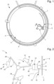
- the striking mechanism 1 is intended for a timepiece 10, such as a watch shown in the figure 1 .
- the timepiece 10 comprises a caseband 2 and a watch movement 3, preferably mechanical, which is for example provided with a plate 4 and a barrel spring to provide the operating energy.
- the embodiment described below is based on the combination of the principle of the “Gauss magnetic cannon” and the principle of conservation of momentum during an impact.
- the striking mechanism 1 comprises a resonant element 5, for example a gong conventionally used in clockwork strikes.
- the resonant element 5 makes it possible to emit a sound when struck.
- the resonant element 5 is a rod comprising a rectilinear portion 6.
- the resonant element 5 is preferably fixed to the plate 4, so as to extend above next to the plate 4, for example in a plane parallel to that of the plate.
- Resonant element 5 may further comprise a circular portion 7, shown in FIG. figure 1 , in particular to run along the inner face of the middle 2.
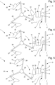
- the mechanism 1 comprises a movable hammer 8 relative to the plate 4.
- the hammer 8 is movable between two positions, a rest position 9 distant from the resonant element 5, and a shock position 11 in which it strikes the resonant element to make it vibrate.
- the resonant element 5 produces a vibration which propagates in the watch.
- the outer part of the watch radiates these vibrations so as to emit a sound.
- Other embodiments are possible with various shapes of hammer 8 and resonant element 5.
- the mechanism 1 here comprises a flexible guide 12 on which the hammer 8 is mounted to allow it to move between its rest position 9 and its impact position 11.
- the flexible guide 12 preferably comprises a first flexible blade 13 assembled to the plate 4 on the one hand, and to the hammer 8 on the other hand.
- the first flexible blade 13 is preferably arranged substantially parallel to the resonant element 5 when the hammer 8 is in the rest position 9. By the elastic deformation of the first flexible blade 13, the hammer 8 passes from the rest position 9 to the impact position 11 and vice versa.
- the mechanism 1 further comprises a magnet 15 fixed relative to the plate 4.
- the magnet 15 is preferably assembled on the plate 4.
- the magnet 15 is for example arranged on a promontory 14 opposite the resonant element 5.
- the magnet 15 is configured to retain the hammer 8 in its rest position 9.
- the hammer 8 comprises a material magnetic conductor, which induces an attractive force of the hammer 8 against the magnet 15.
- a hammer 8 may be selected that does not include a magnetically conductive material.
- the flexible guide 12 is configured to apply a preload to the hammer 8, so as to press it against the magnet 8.
- the hammer 8 in the rest position 9, the hammer 8 is in contact with a front face 29 of the magnet 15.
- the hammer 8 keeps this position permanently, except when it strikes the resonant element 5.
- the flexible guide 12 is assembled to the plate 4 between the promontory 14 and the resonant element 5.
- the hammer 8 can move between the magnet 15 and the resonant element 5 thanks to the flexible guide 12.
- the front face 29 preferably has a substantially flat surface.
- the hammer 8 has, for example, a cylindrical or spherical shape. These rounded shapes make it easier to separate the hammer 8 from the front face 29 of the magnet 15.
- the mechanism 1 comprises a system for actuating the hammer 8.
- This mechanism is configured to cause the movement of the hammer 8 from its rest position 9 to its impact position 11. In particular, it serves to separate the hammer 8 from the magnet 15 and to allow it to reach the resonant element 5.
- the actuation system 20 comprises at least one movable striker 16, 17, 18 configured to transmit to the hammer 8 a sufficient quantity of movement for it to pass from its rest position 9 to its impact position 11 and to vibrate the resonant element 5.
- the striker 16, 17, 18 is configured to move from a trigger position 19 to a percussion position 21 in which it transmits a quantity of movement to the hammer 8.
- the actuation system comprises a rotating device 20 provided with three movable strikers 16, 17, 18.
- the rotating device 20 comprises a hub 22 and three arms 23, 24, 25, distributed angularly around the hub 22, and are connected to the hub 22 by one end.
- Each arm 23, 24, 25 carries a movable striker 16, 17, 18 arranged at the opposite end of the arm 23, 24, 25 relative to the hub 22.
- the arms 23, 24, 25 are preferably arranged in the same plane substantially perpendicular to the axis of the hub 22. This plane also preferably passes through the magnet 15, the hammer 8 and the resonant element 5.
- Each movable striker 16, 17, 18 is mounted on an arm 23, 24, 25 so as to form an angle with the arm 23, 24, 25.
- the angle is between 30 and 60°, when the movable striker 16, 17, 18 is in the trigger position 19, and the angle is between 60 and 90°, when the movable striker 16, 17, 18 is in the percussion position 21.
- An arm can, for example, be an oblong body, a gear tooth or a plate.
- each movable striker 16, 17, 18 is mounted on the arm 23, 24, 25 by a flexible guide to enable it to move relative to the arm 23, 24, 25, and to pass from the trigger position 19 to the percussion position 21.
- the flexible guide here comprises a second flexible blade 26 assembled to the movable striker 16, 17, 18 on the one hand, and on the other hand to the end of the arm 23, 24, 25.
- Each movable striker 16, 17, 18 comprises a contact face 31, 32, 33, which is intended to come into contact with the magnet 15, when it passes from the trigger position 19 to the percussion position 21.
- the contact faces 31, 32, 33 of the movable striker 16, 17, 18 are preferably rounded, to allow easier release when the movable striker 16, 17, 18 returns to its trigger position.
- the rotating device 20 When the rotating device 20 rotates, it positions one of the movable strikers 16, 17, 18 opposite the magnet 15. The movable striker 16, 17, 18 then moves from the trigger position 19 to the percussion position 21 according to a radial displacement. Once the percussion has been carried out, the rotating device 20 continues to rotate in order to prevent the movable striker 16, 17, 18 from remaining against the magnet 15.
- the geometry of the movable strikers 16, 17, 18 is produced so as to require the least possible torque on the rotating device 20. For example, a contact face 32 having a ramp shape tangential to the rotary movement is chosen.
- the rotating device 20 is actuated by rotating the hub 22 about its axis, so that the arms 23, 24, 25 rotate about the axis of the hub 22.
- the movable strikers 16, 17, 18 also rotate about the axis of the hub 22 while remaining in the trigger position 19. In other words, the movable strikers 16, 17, 18 remain in the same position relative to the arms 23, 24, 25, which carry them.
- gear means are mechanically connected to the barrel of the movement by means of gear means, not shown in the figures.
- gear means comprise for example an actuation system configured to determine the chimes to be performed according to the time displayed by the movement 3, to serve in particular as minute repeaters or to signal a programmed alarm time.
- the actuation system triggers the rotation of the hub 22.
- the rotating device 20 is configured to bring the striker into the trigger position 21 in front of the magnet 15.
- the figure 3 shows an example in which the striker 21 is in the trigger position closest to the magnet 15.
- the magnet 15 has an opposite face 30 oriented towards the rotating device 20, so that the opposite face 30 of the magnet 15 and a contact face 31, 32, 33 of a movable striker 16, 17, 18 are opposite each other when the rotating device 20 rotates.
- the opposite face 30 preferably has a substantially flat surface.
- the attractive force of the magnet 15 and the distance between the contact face 31, 32, 33 of the movable striker 16, 17, 18 in the trigger position and the opposite face 30 of the magnet 15 are chosen so that the magnet 15 attracts the striker 16 against its opposite face 30, when it passes in front of its opposite face 30.
- the magnetic potential energy produced by the magnet 15 acting on the movable striker 16, 17, 18 is transformed into kinetic energy by the movable striker 16, 17, 18. This kinetic energy is transmitted to the hammer 8 by the impact of the movable striker 16, 17, 18.
- each movable striker 16, 17, 18 is configured to strike the magnet 15 so as to give an impulse to the hammer.
- the movable strikers 16, 17, 18 and the rotating device 20 are configured so that the amount of movement transmitted to the hammer 8 by the striker 16, 17, 18 is greater than the retaining force of the magnet acting on the hammer 8, so that the hammer detaches from the magnet 15 and strikes the resonant element 5 with sufficient force, as shown in FIG. figure 4 .
- the magnet 15 and the hammer 8 are further configured so that the front face 29 attracts the hammer 8 against it, after it has struck the resonant element 5.
- the hammer 8 returns to its rest position 9, and can be actuated again by the following movable striker 16, 17, 18. This also prevents the hammer 8 from bouncing and striking the resonant element 5 again in an inopportune manner.
- the rotation device 20 pulls on the movable striker 16, 17, 18 so that it detaches from the opposite face 30 of the magnet 15.
- the hub 22 rotates, the next movable striker 16, 17, 18 moves closer to the magnet 15.
- the rotating device 20 is actuated by the movement, when a ringing is required.
- the ringing sounds automatically thanks to the movable strikers 16, 17, 18, the magnet 15, the hammer 8 and the resonant element 5.
- each movable striker 16, 17, 18 strikes the magnet 15 one after the other, to produce a sound each time.
- the hammer 8 strikes the resonant element 5, and returns to the rest position 9 against the magnet 15 between two successive percussions.
- the rotating device is activated for a predefined time.
- the rotation is carried out at a constant speed so that the ringing strokes are emitted periodically at the same frequency.
- the rotation speed can also be varied to emit a particular ringtone.
- the present invention is not limited to the illustrated example but is susceptible to various variants and modifications within the scope of the subject of the appended claim 1.
- the device may comprise a greater or lesser number of arms and strikers than those illustrated in the embodiment described.
Landscapes
- Physics & Mathematics (AREA)
- General Physics & Mathematics (AREA)
- Acoustics & Sound (AREA)
- Electromechanical Clocks (AREA)
Claims (14)
- Schlagwerk (1), insbesondere für ein Uhrwerk (3), wobei das Werk (1) mindestens ein Resonanzelement (5), das es ermöglicht, bei seinem Anschlag einen Ton zu erzeugen, und einen Hammer (8) umfasst, der sich zwischen einer Ruheposition (9) und einer Stoßposition (11) bewegen kann, in der er auf das Resonanzelement (5) aufschlägt, um es in Schwingung zu versetzen, wobei das Schlagwerk (1) ein System zur Betätigung des Hammers (8) umfasst, das einen beweglichen Schlagkörper (16, 17, 18) enthält, der so konfiguriert ist, dass er sich von einer Freigabeposition (19) in eine Schlagposition (21) bewegt, in der er zumindest teilweise sein Moment auf den Hammer (8) überträgt, um ihn von seiner Ruheposition (9) in seine Stoßposition (11) zu bewegen, um das Resonanzelement (5) in Schwingung zu versetzen,
dadurch gekennzeichnet, dass er einen Magneten (15) umfasst, der relativ zum Uhrwerk (3) befestigt ist, wobei der Magnet (15) so konfiguriert ist, dass er den beweglichen Schlagkörper (16, 17, 18) in eine Schlagposition (21) anzieht. - Schlagwerk nach Anspruch 1, dadurch gekennzeichnet, dass der Hammer (8) in seiner Ruheposition (9) mit dem Magneten (15) in Kontakt ist.
- Schlagwerk nach Anspruch 2, dadurch gekennzeichnet, dass der Schlagkörper (16, 17, 18) so konfiguriert ist, dass er auf den Magneten (15) einwirkt, um dem Hammer (8) über den Magneten (15) einen Impuls zu verleihen.
- Schlagwerk nach Anspruch 3, dadurch gekennzeichnet, dass der Abstand zwischen der Freigabeposition (19) des beweglichen Schlagkörpers (16, 17, 18) und dem Magneten (15) so gewählt ist, dass der Magnet (15) den beweglichen Schlagkörper (16, 17, 18) in dessen Schlagposition (21) an sich zieht.
- Schlagwerk nach Anspruch 3 oder 4, dadurch gekennzeichnet, dass der durch den beweglichen Schlagkörper (16, 17, 18) übertragene Impuls die auf den Hammer (8) wirkende magnetische Haltekraft des Magneten (15) überwindet, so dass sich der Hammer (8) vom Magneten (15) löst und auf das Resonanzelement (5) schlägt.
- Schlagwerk nach einem der vorhergehenden Ansprüche, dadurch gekennzeichnet, dass es eine biegsame Führung (12) aufweist, auf der der Hammer (8) montiert ist, um seine Bewegung zwischen seiner Ruheposition (9) und seiner Stoßposition (11) zu ermöglichen.
- Schlagwerk nach einem der vorhergehenden Ansprüche, dadurch gekennzeichnet, dass das Betätigungssystem eine biegsame Führung aufweist, auf der der bewegliche Schlagkörper (16, 17, 18) montiert ist, um seine Bewegung zwischen der Freigabeposition (19) und der Stoßposition (21) zu ermöglichen.
- Schlagwerk nach Anspruch 6 oder 7, dadurch gekennzeichnet, dass die biegsame Führung (12) eine biegsame Lamelle (13, 26, 27, 28) oder einen biegsamen Hals umfasst.
- Schlagwerk nach einem der vorhergehenden Ansprüche, dadurch gekennzeichnet, dass das Betätigungssystem eine Drehvorrichtung (20) aufweist, die mit dem beweglichen Schlagkörper (16, 17, 18) ausgestattet ist, wobei die Drehvorrichtung so gestaltet ist, dass sie den beweglichen Schlagkörper (16, 17, 18) in die Freigabeposition (19) bringt.
- Schlagwerk nach Anspruch 9, dadurch gekennzeichnet, dass das Betätigungssystem mindestens einen zusätzlichen Schlagkörper (16, 17, 18), vorzugsweise zwei zusätzliche Schlagkörper, aufweist, die an der Drehvorrichtung (20) angeordnet sind, um jeden beweglichen Schlagkörper (16, 17, 18) abwechselnd in die Freigabeposition (19) zu bringen.
- Schlagwerk nach einem der vorhergehenden Ansprüche, dadurch gekennzeichnet, dass die Drehvorrichtung (20) eine Nabe (22) aufweist.
- Schlagwerk nach Anspruch 9, dadurch gekennzeichnet, dass die Drehvorrichtung (20) mindestens einen Arm (22, 23, 24) aufweist, wobei jeder Arm (22, 23, 24) einen beweglichen Schlagkörper (16, 17, 18) trägt.
- Schlagwerk nach Anspruch 9, dadurch gekennzeichnet, dass die Drehvorrichtung (20) eine Vielzahl von Armen (22, 23, 24) aufweist, die winklig um die Nabe (22) verteilt sind.
- Uhrwerk (3), dadurch gekennzeichnet, dass es ein Schlagwerk (1) nach einem der vorhergehenden Ansprüche aufweist.
Priority Applications (4)
| Application Number | Priority Date | Filing Date | Title |
|---|---|---|---|
| EP21179616.4A EP4105733B1 (de) | 2021-06-15 | 2021-06-15 | Perkussionsschlagwerk, insbesondere für uhren |
| JP2022093513A JP7407235B2 (ja) | 2021-06-15 | 2022-06-09 | 特に計時器のための、衝撃ストライク機構 |
| US17/836,407 US12248279B2 (en) | 2021-06-15 | 2022-06-09 | Impact striking mechanism, in particular for timepieces |
| CN202210747967.0A CN115480472B (zh) | 2021-06-15 | 2022-06-14 | 尤其用于钟表的撞击式鸣响机构 |
Applications Claiming Priority (1)
| Application Number | Priority Date | Filing Date | Title |
|---|---|---|---|
| EP21179616.4A EP4105733B1 (de) | 2021-06-15 | 2021-06-15 | Perkussionsschlagwerk, insbesondere für uhren |
Publications (2)
| Publication Number | Publication Date |
|---|---|
| EP4105733A1 EP4105733A1 (de) | 2022-12-21 |
| EP4105733B1 true EP4105733B1 (de) | 2024-12-18 |
Family
ID=76483157
Family Applications (1)
| Application Number | Title | Priority Date | Filing Date |
|---|---|---|---|
| EP21179616.4A Active EP4105733B1 (de) | 2021-06-15 | 2021-06-15 | Perkussionsschlagwerk, insbesondere für uhren |
Country Status (4)
| Country | Link |
|---|---|
| US (1) | US12248279B2 (de) |
| EP (1) | EP4105733B1 (de) |
| JP (1) | JP7407235B2 (de) |
| CN (1) | CN115480472B (de) |
Citations (2)
| Publication number | Priority date | Publication date | Assignee | Title |
|---|---|---|---|---|
| CH701699A2 (fr) * | 2009-08-26 | 2011-02-28 | Montres Breguet Sa | Piece d'horlogerie a dispositif de sonnerie munie d'un timbre. |
| EP2707779B1 (de) * | 2011-05-12 | 2020-06-10 | Hublot S.A., Genève | Uhr mit akustischem mechanismus |
Family Cites Families (18)
| Publication number | Priority date | Publication date | Assignee | Title |
|---|---|---|---|---|
| US2948105A (en) * | 1953-06-25 | 1960-08-09 | Manuf Des Montres & Chronograp | Alarm watch |
| US3777701A (en) * | 1972-05-05 | 1973-12-11 | Ansonia Clock Co Inc | Clock chime intensity control |
| CH697380B1 (fr) | 2004-03-09 | 2008-09-15 | Franck Muller Watchland Sa | Pièce d'horlogerie à répétition à minute. |
| JP2008020212A (ja) * | 2006-07-10 | 2008-01-31 | Seiko Epson Corp | 時計 |
| TWI461865B (zh) | 2006-06-23 | 2014-11-21 | Omega Sa | 用於機械式時計機心之擺輪游絲調節系統及具有此系統之時計 |
| JP5206233B2 (ja) | 2007-09-05 | 2013-06-12 | セイコーエプソン株式会社 | 時計および携帯機器 |
| EP2290480B1 (de) * | 2009-08-26 | 2012-04-25 | Montres Breguet SA | Glocke für ein Schlagwerk einer Uhr |
| CH703776A2 (fr) * | 2010-09-13 | 2012-03-15 | Montres Breguet Sa | Montre a sonnerie munie d'un isolateur pour timbre. |
| CH704199A2 (fr) * | 2010-12-10 | 2012-06-15 | Montres Breguet Sa | Mecanisme de sonnerie d'une montre ou d'une boite a musique. |
| CH704198A2 (fr) * | 2010-12-10 | 2012-06-15 | Montres Breguet Sa | Mecanisme de sonnerie d'une montre. |
| CH704392A1 (fr) * | 2011-01-28 | 2012-07-31 | Montres Breguet Sa | Mécanisme de sonnerie d'une montre à blocage du marteau. |
| EP2808745B1 (de) * | 2013-05-28 | 2019-07-03 | Montres Breguet SA | Schlagwerk mit Mitteln zur Auswahl des Vibrationsmodus einer Tonfeder |
| CH710948A2 (fr) * | 2015-04-09 | 2016-10-14 | Montres Breguet Sa | Mécanisme d'activation magnétique de sonnerie d'horlogerie. |
| JP6968814B2 (ja) * | 2015-12-21 | 2021-11-17 | デトラ ソシエテ アノニム | 時計の脱進装置およびそのような装置の動作方法 |
| EP3316046B1 (de) * | 2016-10-25 | 2019-07-31 | The Swatch Group Research and Development Ltd | Verbessertes uhrwerk |
| EP3495895B1 (de) * | 2017-12-11 | 2022-02-23 | Omega SA | Akustischer anzeigemechanismus für uhr, insbesondere chronographen-repetition |
| EP3543801A1 (de) * | 2018-03-21 | 2019-09-25 | Montres Breguet S.A. | Schlagwerkmechanismus einer uhr |
| EP3663869B1 (de) * | 2018-12-06 | 2021-06-16 | Montres Breguet S.A. | Schlagwerkmechanismus einer uhr mit hängehammer |
-
2021
- 2021-06-15 EP EP21179616.4A patent/EP4105733B1/de active Active
-
2022
- 2022-06-09 JP JP2022093513A patent/JP7407235B2/ja active Active
- 2022-06-09 US US17/836,407 patent/US12248279B2/en active Active
- 2022-06-14 CN CN202210747967.0A patent/CN115480472B/zh active Active
Patent Citations (2)
| Publication number | Priority date | Publication date | Assignee | Title |
|---|---|---|---|---|
| CH701699A2 (fr) * | 2009-08-26 | 2011-02-28 | Montres Breguet Sa | Piece d'horlogerie a dispositif de sonnerie munie d'un timbre. |
| EP2707779B1 (de) * | 2011-05-12 | 2020-06-10 | Hublot S.A., Genève | Uhr mit akustischem mechanismus |
Also Published As
| Publication number | Publication date |
|---|---|
| JP2022191178A (ja) | 2022-12-27 |
| US20220397863A1 (en) | 2022-12-15 |
| US12248279B2 (en) | 2025-03-11 |
| CN115480472B (zh) | 2024-05-28 |
| CN115480472A (zh) | 2022-12-16 |
| JP7407235B2 (ja) | 2023-12-28 |
| EP4105733A1 (de) | 2022-12-21 |
Similar Documents
| Publication | Publication Date | Title |
|---|---|---|
| EP2339412B1 (de) | Schlagwerkmechanismus einer Armbanduhr | |
| EP2463731B1 (de) | Schlagwerkmechanismus einer Armbanduhr | |
| EP2808745B1 (de) | Schlagwerk mit Mitteln zur Auswahl des Vibrationsmodus einer Tonfeder | |
| EP2707779B1 (de) | Uhr mit akustischem mechanismus | |
| EP2485097B1 (de) | Schlagwerkmechanismus einer Armbanduhr mit Schlagwerkhammerblockierung | |
| EP3079024B1 (de) | Magnetischer aktivierungsmechanismus für schlagwerke einer uhr | |
| EP2290480A1 (de) | Glocke für ein Schlagwerk einer Uhr | |
| EP2947522B1 (de) | Uhranker für mechanischen Oszillator, und Mechanismus zur Zeitauslösung der Uhr | |
| EP2362279B1 (de) | Schlagwerkmechanismus einer Armbanduhr mit aktiver Dämpfungsgegenfeder | |
| EP2362278B1 (de) | Hammer für Schlagwerkmechanismus einer Armbanduhr | |
| EP4105733B1 (de) | Perkussionsschlagwerk, insbesondere für uhren | |
| EP1272906B1 (de) | Hemmung für uhr | |
| EP4105734B1 (de) | Mikromechanischer mechanismus, der mit einem schlag-betätigungssystem ausgestattet ist, insbesondere für uhren | |
| EP3663869A1 (de) | Schlagwerkmechanismus einer uhr mit hängehammer | |
| CH718729A2 (fr) | Mécanisme de sonnerie à percussion, notamment pour l'horlogerie. | |
| CH718730A2 (fr) | Mécanisme micromécanique à percussion, notamment de sonnerie pour un mouvement d'horlogerie. | |
| CH715617A2 (fr) | Mécanisme de sonnerie d'horlogerie à marteau suspendu. | |
| CH719059A1 (fr) | Dispositif horloger comprenant un marteau comportant deux parties reliées entre elles par un organe de guidage flexible. | |
| HK40078719B (zh) | 尤其用於钟表的撞击式鸣响机构 | |
| CH701699A2 (fr) | Piece d'horlogerie a dispositif de sonnerie munie d'un timbre. | |
| HK40078719A (en) | Impact striking mechanism, in particular for timepieces | |
| CH705303B1 (fr) | Pièce d'horlogerie à mécanisme sonore. | |
| CH702720A2 (fr) | Marteau d'un mecanisme de sonnerie d'une montre. |
Legal Events
| Date | Code | Title | Description |
|---|---|---|---|
| PUAI | Public reference made under article 153(3) epc to a published international application that has entered the european phase |
Free format text: ORIGINAL CODE: 0009012 |
|
| STAA | Information on the status of an ep patent application or granted ep patent |
Free format text: STATUS: THE APPLICATION HAS BEEN PUBLISHED |
|
| AK | Designated contracting states |
Kind code of ref document: A1 Designated state(s): AL AT BE BG CH CY CZ DE DK EE ES FI FR GB GR HR HU IE IS IT LI LT LU LV MC MK MT NL NO PL PT RO RS SE SI SK SM TR |
|
| STAA | Information on the status of an ep patent application or granted ep patent |
Free format text: STATUS: REQUEST FOR EXAMINATION WAS MADE |
|
| P01 | Opt-out of the competence of the unified patent court (upc) registered |
Effective date: 20230611 |
|
| 17P | Request for examination filed |
Effective date: 20230621 |
|
| RBV | Designated contracting states (corrected) |
Designated state(s): AL AT BE BG CH CY CZ DE DK EE ES FI FR GB GR HR HU IE IS IT LI LT LU LV MC MK MT NL NO PL PT RO RS SE SI SK SM TR |
|
| GRAP | Despatch of communication of intention to grant a patent |
Free format text: ORIGINAL CODE: EPIDOSNIGR1 |
|
| STAA | Information on the status of an ep patent application or granted ep patent |
Free format text: STATUS: GRANT OF PATENT IS INTENDED |
|
| RIC1 | Information provided on ipc code assigned before grant |
Ipc: G04B 21/06 20060101AFI20240715BHEP |
|
| INTG | Intention to grant announced |
Effective date: 20240802 |
|
| GRAS | Grant fee paid |
Free format text: ORIGINAL CODE: EPIDOSNIGR3 |
|
| GRAA | (expected) grant |
Free format text: ORIGINAL CODE: 0009210 |
|
| STAA | Information on the status of an ep patent application or granted ep patent |
Free format text: STATUS: THE PATENT HAS BEEN GRANTED |
|
| AK | Designated contracting states |
Kind code of ref document: B1 Designated state(s): AL AT BE BG CH CY CZ DE DK EE ES FI FR GB GR HR HU IE IS IT LI LT LU LV MC MK MT NL NO PL PT RO RS SE SI SK SM TR |
|
| REG | Reference to a national code |
Ref country code: CH Ref legal event code: EP |
|
| REG | Reference to a national code |
Ref country code: DE Ref legal event code: R096 Ref document number: 602021023456 Country of ref document: DE |
|
| REG | Reference to a national code |
Ref country code: IE Ref legal event code: FG4D Free format text: LANGUAGE OF EP DOCUMENT: FRENCH |
|
| REG | Reference to a national code |
Ref country code: LT Ref legal event code: MG9D |
|
| PG25 | Lapsed in a contracting state [announced via postgrant information from national office to epo] |
Ref country code: HR Free format text: LAPSE BECAUSE OF FAILURE TO SUBMIT A TRANSLATION OF THE DESCRIPTION OR TO PAY THE FEE WITHIN THE PRESCRIBED TIME-LIMIT Effective date: 20241218 |
|
| PG25 | Lapsed in a contracting state [announced via postgrant information from national office to epo] |
Ref country code: FI Free format text: LAPSE BECAUSE OF FAILURE TO SUBMIT A TRANSLATION OF THE DESCRIPTION OR TO PAY THE FEE WITHIN THE PRESCRIBED TIME-LIMIT Effective date: 20241218 |
|
| PG25 | Lapsed in a contracting state [announced via postgrant information from national office to epo] |
Ref country code: BG Free format text: LAPSE BECAUSE OF FAILURE TO SUBMIT A TRANSLATION OF THE DESCRIPTION OR TO PAY THE FEE WITHIN THE PRESCRIBED TIME-LIMIT Effective date: 20241218 |
|
| PG25 | Lapsed in a contracting state [announced via postgrant information from national office to epo] |
Ref country code: NO Free format text: LAPSE BECAUSE OF FAILURE TO SUBMIT A TRANSLATION OF THE DESCRIPTION OR TO PAY THE FEE WITHIN THE PRESCRIBED TIME-LIMIT Effective date: 20250318 |
|
| REG | Reference to a national code |
Ref country code: NL Ref legal event code: MP Effective date: 20241218 |
|
| PG25 | Lapsed in a contracting state [announced via postgrant information from national office to epo] |
Ref country code: GR Free format text: LAPSE BECAUSE OF FAILURE TO SUBMIT A TRANSLATION OF THE DESCRIPTION OR TO PAY THE FEE WITHIN THE PRESCRIBED TIME-LIMIT Effective date: 20250319 Ref country code: LV Free format text: LAPSE BECAUSE OF FAILURE TO SUBMIT A TRANSLATION OF THE DESCRIPTION OR TO PAY THE FEE WITHIN THE PRESCRIBED TIME-LIMIT Effective date: 20241218 |
|
| PG25 | Lapsed in a contracting state [announced via postgrant information from national office to epo] |
Ref country code: RS Free format text: LAPSE BECAUSE OF FAILURE TO SUBMIT A TRANSLATION OF THE DESCRIPTION OR TO PAY THE FEE WITHIN THE PRESCRIBED TIME-LIMIT Effective date: 20250318 |
|
| PG25 | Lapsed in a contracting state [announced via postgrant information from national office to epo] |
Ref country code: NL Free format text: LAPSE BECAUSE OF FAILURE TO SUBMIT A TRANSLATION OF THE DESCRIPTION OR TO PAY THE FEE WITHIN THE PRESCRIBED TIME-LIMIT Effective date: 20241218 |
|
| REG | Reference to a national code |
Ref country code: AT Ref legal event code: MK05 Ref document number: 1752727 Country of ref document: AT Kind code of ref document: T Effective date: 20241218 |
|
| PG25 | Lapsed in a contracting state [announced via postgrant information from national office to epo] |
Ref country code: SM Free format text: LAPSE BECAUSE OF FAILURE TO SUBMIT A TRANSLATION OF THE DESCRIPTION OR TO PAY THE FEE WITHIN THE PRESCRIBED TIME-LIMIT Effective date: 20241218 |
|
| PG25 | Lapsed in a contracting state [announced via postgrant information from national office to epo] |
Ref country code: PL Free format text: LAPSE BECAUSE OF FAILURE TO SUBMIT A TRANSLATION OF THE DESCRIPTION OR TO PAY THE FEE WITHIN THE PRESCRIBED TIME-LIMIT Effective date: 20241218 |
|
| PGFP | Annual fee paid to national office [announced via postgrant information from national office to epo] |
Ref country code: DE Payment date: 20250520 Year of fee payment: 5 |
|
| PG25 | Lapsed in a contracting state [announced via postgrant information from national office to epo] |
Ref country code: ES Free format text: LAPSE BECAUSE OF FAILURE TO SUBMIT A TRANSLATION OF THE DESCRIPTION OR TO PAY THE FEE WITHIN THE PRESCRIBED TIME-LIMIT Effective date: 20241218 |
|
| PGFP | Annual fee paid to national office [announced via postgrant information from national office to epo] |
Ref country code: GB Payment date: 20250520 Year of fee payment: 5 |
|
| PG25 | Lapsed in a contracting state [announced via postgrant information from national office to epo] |
Ref country code: IS Free format text: LAPSE BECAUSE OF FAILURE TO SUBMIT A TRANSLATION OF THE DESCRIPTION OR TO PAY THE FEE WITHIN THE PRESCRIBED TIME-LIMIT Effective date: 20250418 |
|
| PG25 | Lapsed in a contracting state [announced via postgrant information from national office to epo] |
Ref country code: PT Free format text: LAPSE BECAUSE OF FAILURE TO SUBMIT A TRANSLATION OF THE DESCRIPTION OR TO PAY THE FEE WITHIN THE PRESCRIBED TIME-LIMIT Effective date: 20250421 |
|
| PG25 | Lapsed in a contracting state [announced via postgrant information from national office to epo] |
Ref country code: EE Free format text: LAPSE BECAUSE OF FAILURE TO SUBMIT A TRANSLATION OF THE DESCRIPTION OR TO PAY THE FEE WITHIN THE PRESCRIBED TIME-LIMIT Effective date: 20241218 |
|
| PGFP | Annual fee paid to national office [announced via postgrant information from national office to epo] |
Ref country code: FR Payment date: 20250520 Year of fee payment: 5 |
|
| PG25 | Lapsed in a contracting state [announced via postgrant information from national office to epo] |
Ref country code: RO Free format text: LAPSE BECAUSE OF FAILURE TO SUBMIT A TRANSLATION OF THE DESCRIPTION OR TO PAY THE FEE WITHIN THE PRESCRIBED TIME-LIMIT Effective date: 20241218 Ref country code: AT Free format text: LAPSE BECAUSE OF FAILURE TO SUBMIT A TRANSLATION OF THE DESCRIPTION OR TO PAY THE FEE WITHIN THE PRESCRIBED TIME-LIMIT Effective date: 20241218 |
|
| PG25 | Lapsed in a contracting state [announced via postgrant information from national office to epo] |
Ref country code: SK Free format text: LAPSE BECAUSE OF FAILURE TO SUBMIT A TRANSLATION OF THE DESCRIPTION OR TO PAY THE FEE WITHIN THE PRESCRIBED TIME-LIMIT Effective date: 20241218 |
|
| PG25 | Lapsed in a contracting state [announced via postgrant information from national office to epo] |
Ref country code: CZ Free format text: LAPSE BECAUSE OF FAILURE TO SUBMIT A TRANSLATION OF THE DESCRIPTION OR TO PAY THE FEE WITHIN THE PRESCRIBED TIME-LIMIT Effective date: 20241218 |
|
| PG25 | Lapsed in a contracting state [announced via postgrant information from national office to epo] |
Ref country code: IT Free format text: LAPSE BECAUSE OF FAILURE TO SUBMIT A TRANSLATION OF THE DESCRIPTION OR TO PAY THE FEE WITHIN THE PRESCRIBED TIME-LIMIT Effective date: 20241218 |
|
| PG25 | Lapsed in a contracting state [announced via postgrant information from national office to epo] |
Ref country code: SE Free format text: LAPSE BECAUSE OF FAILURE TO SUBMIT A TRANSLATION OF THE DESCRIPTION OR TO PAY THE FEE WITHIN THE PRESCRIBED TIME-LIMIT Effective date: 20241218 |
|
| REG | Reference to a national code |
Ref country code: DE Ref legal event code: R097 Ref document number: 602021023456 Country of ref document: DE |
|
| PG25 | Lapsed in a contracting state [announced via postgrant information from national office to epo] |
Ref country code: DK Free format text: LAPSE BECAUSE OF FAILURE TO SUBMIT A TRANSLATION OF THE DESCRIPTION OR TO PAY THE FEE WITHIN THE PRESCRIBED TIME-LIMIT Effective date: 20241218 |
|
| PGFP | Annual fee paid to national office [announced via postgrant information from national office to epo] |
Ref country code: CH Payment date: 20250701 Year of fee payment: 5 |
|
| PLBE | No opposition filed within time limit |
Free format text: ORIGINAL CODE: 0009261 |
|
| STAA | Information on the status of an ep patent application or granted ep patent |
Free format text: STATUS: NO OPPOSITION FILED WITHIN TIME LIMIT |
|
| 26N | No opposition filed |
Effective date: 20250919 |
|
| PG25 | Lapsed in a contracting state [announced via postgrant information from national office to epo] |
Ref country code: MC Free format text: LAPSE BECAUSE OF FAILURE TO SUBMIT A TRANSLATION OF THE DESCRIPTION OR TO PAY THE FEE WITHIN THE PRESCRIBED TIME-LIMIT Effective date: 20241218 |
|
| PG25 | Lapsed in a contracting state [announced via postgrant information from national office to epo] |
Ref country code: LU Free format text: LAPSE BECAUSE OF NON-PAYMENT OF DUE FEES Effective date: 20250615 |
|
| REG | Reference to a national code |
Ref country code: BE Ref legal event code: MM Effective date: 20250630 |
|
| PG25 | Lapsed in a contracting state [announced via postgrant information from national office to epo] |
Ref country code: IE Free format text: LAPSE BECAUSE OF NON-PAYMENT OF DUE FEES Effective date: 20250615 |
|
| PG25 | Lapsed in a contracting state [announced via postgrant information from national office to epo] |
Ref country code: BE Free format text: LAPSE BECAUSE OF NON-PAYMENT OF DUE FEES Effective date: 20250630 |