EP4112440B1 - Hélice à pas variable auto-réglable - Google Patents
Hélice à pas variable auto-réglable Download PDFInfo
- Publication number
- EP4112440B1 EP4112440B1 EP21182266.3A EP21182266A EP4112440B1 EP 4112440 B1 EP4112440 B1 EP 4112440B1 EP 21182266 A EP21182266 A EP 21182266A EP 4112440 B1 EP4112440 B1 EP 4112440B1
- Authority
- EP
- European Patent Office
- Prior art keywords
- blade
- hub
- variable pitch
- pitch propeller
- blades
- Prior art date
- Legal status (The legal status is an assumption and is not a legal conclusion. Google has not performed a legal analysis and makes no representation as to the accuracy of the status listed.)
- Active
Links
Images


Classifications
-
- B—PERFORMING OPERATIONS; TRANSPORTING
- B63—SHIPS OR OTHER WATERBORNE VESSELS; RELATED EQUIPMENT
- B63H—MARINE PROPULSION OR STEERING
- B63H3/00—Propeller-blade pitch changing
- B63H3/008—Propeller-blade pitch changing characterised by self-adjusting pitch, e.g. by means of springs, centrifugal forces, hydrodynamic forces
-
- B—PERFORMING OPERATIONS; TRANSPORTING
- B63—SHIPS OR OTHER WATERBORNE VESSELS; RELATED EQUIPMENT
- B63H—MARINE PROPULSION OR STEERING
- B63H20/00—Outboard propulsion units, e.g. outboard motors or Z-drives; Arrangements thereof on vessels
- B63H20/24—Arrangements, apparatus and methods for handling exhaust gas in outboard drives, e.g. exhaust gas outlets
- B63H20/245—Exhaust gas outlets
Definitions
- An object of the present invention is to provide an enhanced self-adjusting variable pitch propeller for marine use.
- the at least one interconnecting member may comprise a ring-shaped member and the second gear teeth of the ring-shaped member may mesh with the first gear teeth of all blade roots.
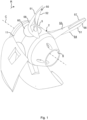
- the present disclosure provides a self-adjusting variable pitch propeller for marine use which propeller comprises a central hub with an axial propeller centre line defining the rotational axis of the propeller and a plurality of blades extending radially from the hub, wherein the hub exhibits a central bore arranged to receive a rotating drive shaft, each blade is pivotally fixed to the hub and pivotal about a respective blade pivot axis which extends radially from the hub, the blades are mechanically interconnected to transfer pivotal movement of each blade to all other blades and wherein the hub exhibits an axially extending exhaust channel for transportation of exhaust gases.
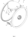
- the hub may comprise an exhaust turbine which is fixed to the hub and arranged in the exhaust channel.
- the hub may comprise a central sleeve exhibiting the central bore and a peripheral sleeve concentrically arranged with and outside the central sleeve thereby forming the exhaust channel between the central sleeve and the peripheral sleeve.
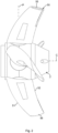
- Each blade further comprises a bladelet 55 or vortex reducer which is arranged at the blade tip 56 being positioned at the radially outer end of the blade 50.
- the bladelet 55 is formed as a protrusion or bead which protrudes from the blade tip 56 edge towards the suction side 53 and reduces water flow from the suction side to the pressure side 54, over the blade tip to thereby reduce cavitation at the blade tip 56.
- the length of the bladelet 55 is preferably approx. 5-15% of the total radial length of the blade 50.
- the blade 50 further comprises a blade diffuser 57 or separation delayer which is arranged at the trailing edge 52 and extends from the blade tip 56 inwardly, approx. half the way towards the hub 10.
- the blade diffuser 57 comprises a portion of the blade in the region adjacent the trailing edge, which portion is bent or curved towards the suction side 53.
- the length of the blade diffuser in the rotational direction R of the propeller is approx. 10-15% of the distance between the leading 51 and trailing 52 edge at the blade diffuser.
- the blade diffuser 57 reduces the water resistance experienced by the propeller to thereby increase the efficiency and reduce fuel consumption.
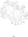
- the blade further exhibits a through opening 58 which is arranged at the radially inner half of the blade.
- the area of the through opening 58 constitutes approx. 30% of the radially inner half of the suction side 53 area.
- the gear arrangement comprises interconnecting members 71, 72 arranged to mechanically interconnect the blade roots 60 for synchronising the pivotal movement of the blades 50.
- the gear arrangement comprises two different types of interconnecting members 71, 72.
- Fig 7 is a side view corresponding to the view in fig 2 illustrating an exemplifying blade 50' (without the blade root) according to a second embodiment.
- Fig. 7 shows the pressure side of the blade 50'
- Fig. 8 is a plan view from the front of the propeller showing the suction side of the propeller 50' shown in fig 7 .
- the direction of the propeller centre line C has been schematically indicated for reference purposes.
Landscapes
- Engineering & Computer Science (AREA)
- Chemical & Material Sciences (AREA)
- Combustion & Propulsion (AREA)
- Mechanical Engineering (AREA)
- Ocean & Marine Engineering (AREA)
- Physics & Mathematics (AREA)
- Fluid Mechanics (AREA)
- Aviation & Aerospace Engineering (AREA)
- Structures Of Non-Positive Displacement Pumps (AREA)
- General Details Of Gearings (AREA)
- Working-Up Tar And Pitch (AREA)
Claims (16)
- Hélice à pas variable autoréglable (1) destinée à une utilisation marine, comprenant un moyeu central (2) avec une ligne centrale axiale d'hélice (C) définissant l'axe de rotation de l'hélice et une pluralité de pales (50, 50') s'étendant radialement à partir du moyeu,- le moyeu (2) présentant un alésage central (3) agencé pour recevoir un arbre d'entraînement rotatif (S),- chaque pale (50, 50') étant fixée de manière à pouvoir pivoter au moyeu (2) et à pouvoir pivoter autour d'un axe de pivotement de pale correspondant (P) qui s'étend radialement depuis le moyeu (2) à travers la pale correspondante (50, 50'),- chaque pale (50, 50') présentant un bord d'attaque (51, 51'), un bord de fuite (52, 52'), un côté pression (54, 54') présentant une surface côté pression et un côté aspiration (53, 53') présentant une surface côté aspiration,caractérisée en ce que- les pales (50) sont interconnectées mécaniquement pour transférer librement le mouvement pivotant de chaque pale à toutes les autres pales et où- l'axe de pivotement (P) de chaque pale (50, 50') est positionné de telle sorte que > 50 % de la surface côté aspiration (53, 53') et de la surface côté pression (54, 54') soient disposés entre le bord de fuite (52, 52') et l'axe de pivotement (P) de la pale concernée (50, 50').
- Hélice à pas variable autoréglable selon la revendication 1, dans laquelle ≤ 92 % de la surface du côté aspiration (53, 53') et ≤ 96 % de la surface du côté pression (54, 54') sont disposés entre le bord de fuite (52, 52') et l'axe de pivotement (P) de chaque pale (50, 50').
- Hélice à pas variable autoréglable selon la revendication 1 ou 2, dans laquelle chaque pale (50, 50') peut pivoter de manière limitée autour de l'axe de pivotement (P) entre un angle de pivotement minimum et un angle de pivotement maximum.
- Hélice à pas variable autoréglable selon la revendication 3, dans laquelle chaque pale (50, 50') est formée de telle sorte que l'angle de pivotement minimum corresponde à un pas de 7 pouces et l'angle de pivotement maximum corresponde à un pas de 27 pouces.
- Hélice à pas variable selon l'une quelconque des revendications 1 à 4, dans laquelle chaque pale (50, 50') est fixée à ou formée d'un seul tenant avec un pied de pale correspondant (60).
- Hélice à pas variable selon l'une quelconque des revendications 1 à 5, dans laquelle les pales (50, 50') sont interconnectées mécaniquement au moyen d'un agencement d'engrenage (70).
- Hélice à pas variable selon la revendication 6, dans laquelle l'agencement d'engrenage (70) comprend des premières dents d'engrenage (62, 63) disposées sur chaque pied de pale (60) et des secondes dents d'engrenage (71a, 72a) disposées sur au moins un élément d'interconnexion (71, 72).
- Hélice à pas variable selon la revendication 7, dans laquelle l'au moins un élément d'interconnexion comprend un élément de forme annulaire (71) et les secondes dents d'engrenage (71a) de l'élément de forme annulaire (71) s'engrènent avec les premières dents d'engrenage (62) de tous les pieds de pale (60).
- Hélice à pas variable selon la revendication 7 ou 8, dans laquelle l'au moins un élément d'interconnexion comprend une pluralité de roues dentées (72) et dans laquelle les secondes dents d'engrenage (72a) de chaque roue dentée (72) s'engrènent avec les premières dents d'engrenage (63) de deux pieds de pale mutuellement adjacents (60).
- Hélice à pas variable selon l'une quelconque des revendications 1 à 9, dans laquelle le moyeu (2) présente un canal d'échappement (6) s'étendant axialement pour le transport des gaz d'échappement.
- Hélice à pas variable selon la revendication 10, dans laquelle le canal d'échappement (6) est annulaire et disposé concentriquement autour de l'alésage central (3) du moyeu (2).
- Hélice à pas variable selon la revendication 10 ou 11, dans laquelle le moyeu (2) comprend une turbine d'échappement (8) qui est fixée au moyeu (2) et disposée dans le canal d'échappement (6).
- Hélice à pas variable selon l'une quelconque des revendications 10 à 12, dans laquelle le moyeu (2) comprend un manchon central (4) présentant l'alésage central (3) et un manchon périphérique (5) disposé concentriquement avec et à l'extérieur du manchon central (4), en formant ainsi le canal d'échappement (6) entre le manchon central (4) et le manchon périphérique (5).
- Hélice à pas variable selon la revendication 13, dans laquelle le manchon périphérique (5) est relié au manchon central (4) au moyen de rayons (14a, 24a, 34a, 44a-d) agencés en hélice qui forment des pales de turbine (7a-d) de la turbine d'échappement (8).
- Hélice à pas variable selon l'une quelconque des revendications 1 à 14, dans laquelle le moyeu (2) comporte au moins deux segments (10, 20, 30, 40) qui sont mutuellement fixés l'un après l'autre dans la direction axiale de l'hélice et dans laquelle les pales (50) sont fixées au moyeu au niveau d'évidements correspondants (25a, 35a) formés dans le moyeu à la jonction entre deux segments (20, 30).
- Hélice à pas variable selon l'une quelconque des revendications 1 à 15, dans laquelle le nombre de pales (50) est compris entre deux et huit, de préférence entre trois et cinq.
Priority Applications (9)
| Application Number | Priority Date | Filing Date | Title |
|---|---|---|---|
| FIEP21182266.3T FI4112440T3 (fi) | 2021-06-29 | 2021-06-29 | Itsesäätyvä nousultaan muutettava potkuri |
| EP21182266.3A EP4112440B1 (fr) | 2021-06-29 | 2021-06-29 | Hélice à pas variable auto-réglable |
| HRP20250646TT HRP20250646T1 (hr) | 2021-06-29 | 2021-06-29 | Samo-podesivi propeler promjenjivog koraka |
| JP2023579551A JP2024524307A (ja) | 2021-06-29 | 2022-06-28 | 自己調節式可変ピッチプロペラ |
| PCT/EP2022/067711 WO2023275040A1 (fr) | 2021-06-29 | 2022-06-28 | Hélice à pas variable à réglage automatique |
| EP22735442.0A EP4363308A1 (fr) | 2021-06-29 | 2022-06-28 | Hélice à pas variable à réglage automatique |
| AU2022302792A AU2022302792B2 (en) | 2021-06-29 | 2022-06-28 | A self-adjusting variable pitch propeller |
| US18/573,911 US12103656B2 (en) | 2021-06-29 | 2022-06-28 | Self-adjusting variable pitch propeller |
| CA3222275A CA3222275A1 (fr) | 2021-06-29 | 2022-06-28 | Helice a pas variable a reglage automatique |
Applications Claiming Priority (1)
| Application Number | Priority Date | Filing Date | Title |
|---|---|---|---|
| EP21182266.3A EP4112440B1 (fr) | 2021-06-29 | 2021-06-29 | Hélice à pas variable auto-réglable |
Publications (2)
| Publication Number | Publication Date |
|---|---|
| EP4112440A1 EP4112440A1 (fr) | 2023-01-04 |
| EP4112440B1 true EP4112440B1 (fr) | 2025-04-09 |
Family
ID=76707994
Family Applications (2)
| Application Number | Title | Priority Date | Filing Date |
|---|---|---|---|
| EP21182266.3A Active EP4112440B1 (fr) | 2021-06-29 | 2021-06-29 | Hélice à pas variable auto-réglable |
| EP22735442.0A Pending EP4363308A1 (fr) | 2021-06-29 | 2022-06-28 | Hélice à pas variable à réglage automatique |
Family Applications After (1)
| Application Number | Title | Priority Date | Filing Date |
|---|---|---|---|
| EP22735442.0A Pending EP4363308A1 (fr) | 2021-06-29 | 2022-06-28 | Hélice à pas variable à réglage automatique |
Country Status (8)
| Country | Link |
|---|---|
| US (1) | US12103656B2 (fr) |
| EP (2) | EP4112440B1 (fr) |
| JP (1) | JP2024524307A (fr) |
| AU (1) | AU2022302792B2 (fr) |
| CA (1) | CA3222275A1 (fr) |
| FI (1) | FI4112440T3 (fr) |
| HR (1) | HRP20250646T1 (fr) |
| WO (1) | WO2023275040A1 (fr) |
Family Cites Families (13)
| Publication number | Priority date | Publication date | Assignee | Title |
|---|---|---|---|---|
| US2246539A (en) * | 1938-08-20 | 1941-06-24 | Robert J Ruths | Variable pitch propeller |
| US2682926A (en) * | 1950-03-20 | 1954-07-06 | Laurence J Evans | Automatic variable pitch propeller |
| US3308889A (en) | 1965-07-06 | 1967-03-14 | Finn Bergishagen | Variable pitch propeller with automatic adjustment |
| US4140434A (en) * | 1975-12-29 | 1979-02-20 | Massimiliano Bianchi | Feathering propeller especially for sailing boats |
| GB2058231B (en) | 1979-09-07 | 1982-01-20 | Woodcoxon Eng International Lt | Variable pitch marine propellers |
| US4693671A (en) * | 1986-08-28 | 1987-09-15 | Tramtec Corporation | Reversible self-adjusting propeller device |
| US5326223A (en) * | 1988-07-07 | 1994-07-05 | Speer Stephen R | Automatic variable pitch marine propeller with mechanical holding means |
| US5290147A (en) * | 1991-12-02 | 1994-03-01 | Brunswick Corporation | Variable pitch marine propeller with shift biasing and synchronizing mechanism |
| US5549455A (en) * | 1992-07-15 | 1996-08-27 | Aerostar Marine Corporation | Through the hub exhaust flow improvements for marine variable pitch propeller |
| JP3252042B2 (ja) * | 1993-12-27 | 2002-01-28 | 本田技研工業株式会社 | 船用の可変プロペラ |
| US5851131A (en) * | 1997-06-16 | 1998-12-22 | Land And Sea, Inc. | Self-adjusting variable pitch propeller |
| EP2275343B1 (fr) * | 2006-12-19 | 2012-05-09 | Max Prop S.r.l. | Propulseur à tangage variable |
| CN102050219A (zh) * | 2010-12-29 | 2011-05-11 | 广州中船龙穴造船有限公司 | 可变螺距船用螺旋桨 |
-
2021
- 2021-06-29 HR HRP20250646TT patent/HRP20250646T1/hr unknown
- 2021-06-29 EP EP21182266.3A patent/EP4112440B1/fr active Active
- 2021-06-29 FI FIEP21182266.3T patent/FI4112440T3/fi active
-
2022
- 2022-06-28 US US18/573,911 patent/US12103656B2/en active Active
- 2022-06-28 JP JP2023579551A patent/JP2024524307A/ja active Pending
- 2022-06-28 CA CA3222275A patent/CA3222275A1/fr active Pending
- 2022-06-28 EP EP22735442.0A patent/EP4363308A1/fr active Pending
- 2022-06-28 AU AU2022302792A patent/AU2022302792B2/en active Active
- 2022-06-28 WO PCT/EP2022/067711 patent/WO2023275040A1/fr not_active Ceased
Also Published As
| Publication number | Publication date |
|---|---|
| HRP20250646T1 (hr) | 2025-07-18 |
| CA3222275A1 (fr) | 2023-01-05 |
| AU2022302792A1 (en) | 2023-12-21 |
| FI4112440T3 (fi) | 2025-06-11 |
| JP2024524307A (ja) | 2024-07-05 |
| AU2022302792B2 (en) | 2024-12-12 |
| EP4363308A1 (fr) | 2024-05-08 |
| US20240262477A1 (en) | 2024-08-08 |
| EP4112440A1 (fr) | 2023-01-04 |
| US12103656B2 (en) | 2024-10-01 |
| WO2023275040A1 (fr) | 2023-01-05 |
Similar Documents
| Publication | Publication Date | Title |
|---|---|---|
| US11511837B2 (en) | Hybrid propulsor for watercraft | |
| US6352408B1 (en) | Slip inhibiting boat propeller | |
| EP3495257B1 (fr) | Petit conduit de réglage d'hélice et navire | |
| EP2902312A1 (fr) | Hélices marines | |
| US11945562B1 (en) | Shovel blade airplane/boat propeller | |
| US5527195A (en) | Flow through marine propeller | |
| EP4112440B1 (fr) | Hélice à pas variable auto-réglable | |
| EP1871659B1 (fr) | Systeme de propulsion et de guidage pour navire | |
| KR101599383B1 (ko) | 해수에서 작동 가능한 보조 추진기 클러치 시스템 | |
| US12286203B2 (en) | Hybrid propulsor for watercraft | |
| US4834683A (en) | Apparatus for reducing exhaust gas pressure in outboard and inboard/outboard motors | |
| US11772763B1 (en) | Marine accelerating propeller | |
| WO1997015489A1 (fr) | Helice amelioree | |
| KR102871402B1 (ko) | 유체에 추력을 가하기 위한 추진 디바이스 | |
| KR101599388B1 (ko) | 선박용 보조 추진기 | |
| CA3259665C (fr) | Dispositif de propulsion pour exercer une poussée sur un fluide | |
| JP7580323B2 (ja) | 船舶推進装置、船舶 | |
| JP3339010B2 (ja) | 船舶用プロペラ | |
| JP2024141683A (ja) | 船舶用推進装置及びそれを備えた船舶 | |
| EP1541461A1 (fr) | Helice, systeme de propulsion par helice et navire comprenant un systeme de propulsion |
Legal Events
| Date | Code | Title | Description |
|---|---|---|---|
| REG | Reference to a national code |
Ref country code: HR Ref legal event code: TUEP Ref document number: P20250646T Country of ref document: HR |
|
| PUAI | Public reference made under article 153(3) epc to a published international application that has entered the european phase |
Free format text: ORIGINAL CODE: 0009012 |
|
| STAA | Information on the status of an ep patent application or granted ep patent |
Free format text: STATUS: THE APPLICATION HAS BEEN PUBLISHED |
|
| AK | Designated contracting states |
Kind code of ref document: A1 Designated state(s): AL AT BE BG CH CY CZ DE DK EE ES FI FR GB GR HR HU IE IS IT LI LT LU LV MC MK MT NL NO PL PT RO RS SE SI SK SM TR |
|
| STAA | Information on the status of an ep patent application or granted ep patent |
Free format text: STATUS: REQUEST FOR EXAMINATION WAS MADE |
|
| 17P | Request for examination filed |
Effective date: 20230622 |
|
| RBV | Designated contracting states (corrected) |
Designated state(s): AL AT BE BG CH CY CZ DE DK EE ES FI FR GB GR HR HU IE IS IT LI LT LU LV MC MK MT NL NO PL PT RO RS SE SI SK SM TR |
|
| GRAP | Despatch of communication of intention to grant a patent |
Free format text: ORIGINAL CODE: EPIDOSNIGR1 |
|
| STAA | Information on the status of an ep patent application or granted ep patent |
Free format text: STATUS: GRANT OF PATENT IS INTENDED |
|
| INTG | Intention to grant announced |
Effective date: 20241106 |
|
| GRAS | Grant fee paid |
Free format text: ORIGINAL CODE: EPIDOSNIGR3 |
|
| GRAA | (expected) grant |
Free format text: ORIGINAL CODE: 0009210 |
|
| STAA | Information on the status of an ep patent application or granted ep patent |
Free format text: STATUS: THE PATENT HAS BEEN GRANTED |
|
| AK | Designated contracting states |
Kind code of ref document: B1 Designated state(s): AL AT BE BG CH CY CZ DE DK EE ES FI FR GB GR HR HU IE IS IT LI LT LU LV MC MK MT NL NO PL PT RO RS SE SI SK SM TR |
|
| REG | Reference to a national code |
Ref country code: GB Ref legal event code: FG4D |
|
| RIN1 | Information on inventor provided before grant (corrected) |
Inventor name: ANDERSSON, MATHIAS Inventor name: AENGGARD, JOHN Inventor name: BANG, EMIL |
|
| REG | Reference to a national code |
Ref country code: CH Ref legal event code: EP |
|
| REG | Reference to a national code |
Ref country code: DE Ref legal event code: R096 Ref document number: 602021028788 Country of ref document: DE |
|
| REG | Reference to a national code |
Ref country code: IE Ref legal event code: FG4D |
|
| REG | Reference to a national code |
Ref country code: FI Ref legal event code: FGE |
|
| REG | Reference to a national code |
Ref country code: NL Ref legal event code: FP |
|
| REG | Reference to a national code |
Ref country code: SE Ref legal event code: TRGR |
|
| PGFP | Annual fee paid to national office [announced via postgrant information from national office to epo] |
Ref country code: SM Payment date: 20250630 Year of fee payment: 5 |
|
| REG | Reference to a national code |
Ref country code: HR Ref legal event code: ODRP Ref document number: P20250646T Country of ref document: HR Payment date: 20250602 Year of fee payment: 5 |
|
| PGFP | Annual fee paid to national office [announced via postgrant information from national office to epo] |
Ref country code: MC Payment date: 20250623 Year of fee payment: 5 |
|
| PGFP | Annual fee paid to national office [announced via postgrant information from national office to epo] |
Ref country code: DE Payment date: 20250618 Year of fee payment: 5 |
|
| PGFP | Annual fee paid to national office [announced via postgrant information from national office to epo] |
Ref country code: NO Payment date: 20250618 Year of fee payment: 5 |
|
| PGFP | Annual fee paid to national office [announced via postgrant information from national office to epo] |
Ref country code: LU Payment date: 20250616 Year of fee payment: 5 Ref country code: NL Payment date: 20250618 Year of fee payment: 5 Ref country code: BE Payment date: 20250618 Year of fee payment: 5 |
|
| PGFP | Annual fee paid to national office [announced via postgrant information from national office to epo] |
Ref country code: HR Payment date: 20250602 Year of fee payment: 5 |
|
| PGFP | Annual fee paid to national office [announced via postgrant information from national office to epo] |
Ref country code: FR Payment date: 20250617 Year of fee payment: 5 |
|
| REG | Reference to a national code |
Ref country code: HR Ref legal event code: T1PR Ref document number: P20250646 Country of ref document: HR |
|
| PGFP | Annual fee paid to national office [announced via postgrant information from national office to epo] |
Ref country code: GR Payment date: 20250619 Year of fee payment: 5 |
|
| PGFP | Annual fee paid to national office [announced via postgrant information from national office to epo] |
Ref country code: AT Payment date: 20250721 Year of fee payment: 5 |
|
| PGFP | Annual fee paid to national office [announced via postgrant information from national office to epo] |
Ref country code: CZ Payment date: 20250530 Year of fee payment: 5 |
|
| PGFP | Annual fee paid to national office [announced via postgrant information from national office to epo] |
Ref country code: SE Payment date: 20250618 Year of fee payment: 5 |
|
| REG | Reference to a national code |
Ref country code: GR Ref legal event code: EP Ref document number: 20250401077 Country of ref document: GR Effective date: 20250613 |
|
| PG25 | Lapsed in a contracting state [announced via postgrant information from national office to epo] |
Ref country code: PT Free format text: LAPSE BECAUSE OF FAILURE TO SUBMIT A TRANSLATION OF THE DESCRIPTION OR TO PAY THE FEE WITHIN THE PRESCRIBED TIME-LIMIT Effective date: 20250811 Ref country code: ES Free format text: LAPSE BECAUSE OF FAILURE TO SUBMIT A TRANSLATION OF THE DESCRIPTION OR TO PAY THE FEE WITHIN THE PRESCRIBED TIME-LIMIT Effective date: 20250409 |
|
| PGFP | Annual fee paid to national office [announced via postgrant information from national office to epo] |
Ref country code: FI Payment date: 20250717 Year of fee payment: 5 |
|
| REG | Reference to a national code |
Ref country code: LT Ref legal event code: MG9D |
|
| PG25 | Lapsed in a contracting state [announced via postgrant information from national office to epo] |
Ref country code: PL Free format text: LAPSE BECAUSE OF FAILURE TO SUBMIT A TRANSLATION OF THE DESCRIPTION OR TO PAY THE FEE WITHIN THE PRESCRIBED TIME-LIMIT Effective date: 20250409 |
|
| PGFP | Annual fee paid to national office [announced via postgrant information from national office to epo] |
Ref country code: IT Payment date: 20250728 Year of fee payment: 5 |
|
| PG25 | Lapsed in a contracting state [announced via postgrant information from national office to epo] |
Ref country code: BG Free format text: LAPSE BECAUSE OF FAILURE TO SUBMIT A TRANSLATION OF THE DESCRIPTION OR TO PAY THE FEE WITHIN THE PRESCRIBED TIME-LIMIT Effective date: 20250409 |
|
| PGFP | Annual fee paid to national office [announced via postgrant information from national office to epo] |
Ref country code: GB Payment date: 20250721 Year of fee payment: 5 |
|
| PGFP | Annual fee paid to national office [announced via postgrant information from national office to epo] |
Ref country code: CH Payment date: 20250918 Year of fee payment: 5 |
|
| PG25 | Lapsed in a contracting state [announced via postgrant information from national office to epo] |
Ref country code: RS Free format text: LAPSE BECAUSE OF FAILURE TO SUBMIT A TRANSLATION OF THE DESCRIPTION OR TO PAY THE FEE WITHIN THE PRESCRIBED TIME-LIMIT Effective date: 20250709 |
|
| PG25 | Lapsed in a contracting state [announced via postgrant information from national office to epo] |
Ref country code: IS Free format text: LAPSE BECAUSE OF FAILURE TO SUBMIT A TRANSLATION OF THE DESCRIPTION OR TO PAY THE FEE WITHIN THE PRESCRIBED TIME-LIMIT Effective date: 20250809 |
|
| PG25 | Lapsed in a contracting state [announced via postgrant information from national office to epo] |
Ref country code: LV Free format text: LAPSE BECAUSE OF FAILURE TO SUBMIT A TRANSLATION OF THE DESCRIPTION OR TO PAY THE FEE WITHIN THE PRESCRIBED TIME-LIMIT Effective date: 20250409 |
|
| REG | Reference to a national code |
Ref country code: DE Ref legal event code: R097 Ref document number: 602021028788 Country of ref document: DE |
|
| PG25 | Lapsed in a contracting state [announced via postgrant information from national office to epo] |
Ref country code: DK Free format text: LAPSE BECAUSE OF FAILURE TO SUBMIT A TRANSLATION OF THE DESCRIPTION OR TO PAY THE FEE WITHIN THE PRESCRIBED TIME-LIMIT Effective date: 20250409 |
|
| PGFP | Annual fee paid to national office [announced via postgrant information from national office to epo] |
Ref country code: CY Payment date: 20250610 Year of fee payment: 5 |
|
| PG25 | Lapsed in a contracting state [announced via postgrant information from national office to epo] |
Ref country code: EE Free format text: LAPSE BECAUSE OF FAILURE TO SUBMIT A TRANSLATION OF THE DESCRIPTION OR TO PAY THE FEE WITHIN THE PRESCRIBED TIME-LIMIT Effective date: 20250409 |
|
| PG25 | Lapsed in a contracting state [announced via postgrant information from national office to epo] |
Ref country code: SK Free format text: LAPSE BECAUSE OF FAILURE TO SUBMIT A TRANSLATION OF THE DESCRIPTION OR TO PAY THE FEE WITHIN THE PRESCRIBED TIME-LIMIT Effective date: 20250409 |
|
| PG25 | Lapsed in a contracting state [announced via postgrant information from national office to epo] |
Ref country code: RO Free format text: LAPSE BECAUSE OF FAILURE TO SUBMIT A TRANSLATION OF THE DESCRIPTION OR TO PAY THE FEE WITHIN THE PRESCRIBED TIME-LIMIT Effective date: 20250409 |
|
| PLBE | No opposition filed within time limit |
Free format text: ORIGINAL CODE: 0009261 |
|
| STAA | Information on the status of an ep patent application or granted ep patent |
Free format text: STATUS: NO OPPOSITION FILED WITHIN TIME LIMIT |
|
| REG | Reference to a national code |
Ref country code: CH Ref legal event code: L10 Free format text: ST27 STATUS EVENT CODE: U-0-0-L10-L00 (AS PROVIDED BY THE NATIONAL OFFICE) Effective date: 20260218 |
|
| 26N | No opposition filed |
Effective date: 20260112 |
|
| PG25 | Lapsed in a contracting state [announced via postgrant information from national office to epo] |
Ref country code: IE Free format text: LAPSE BECAUSE OF NON-PAYMENT OF DUE FEES Effective date: 20250629 |