EP4112857B1 - Scharnier mit schnappbetätigung mit gedämpftem schliess- und öffnungswinkel von mehr als 90° - Google Patents
Scharnier mit schnappbetätigung mit gedämpftem schliess- und öffnungswinkel von mehr als 90° Download PDFInfo
- Publication number
- EP4112857B1 EP4112857B1 EP22188428.1A EP22188428A EP4112857B1 EP 4112857 B1 EP4112857 B1 EP 4112857B1 EP 22188428 A EP22188428 A EP 22188428A EP 4112857 B1 EP4112857 B1 EP 4112857B1
- Authority
- EP
- European Patent Office
- Prior art keywords
- lever
- pivot
- hinge
- quadrilateral
- fixing plate
- Prior art date
- Legal status (The legal status is an assumption and is not a legal conclusion. Google has not performed a legal analysis and makes no representation as to the accuracy of the status listed.)
- Active
Links
Images


Classifications
-
- E—FIXED CONSTRUCTIONS
- E05—LOCKS; KEYS; WINDOW OR DOOR FITTINGS; SAFES
- E05D—HINGES OR SUSPENSION DEVICES FOR DOORS, WINDOWS OR WINGS
- E05D3/00—Hinges with pins
- E05D3/06—Hinges with pins with two or more pins
- E05D3/16—Hinges with pins with two or more pins with seven parallel pins and four arms
-
- E—FIXED CONSTRUCTIONS
- E05—LOCKS; KEYS; WINDOW OR DOOR FITTINGS; SAFES
- E05D—HINGES OR SUSPENSION DEVICES FOR DOORS, WINDOWS OR WINGS
- E05D11/00—Additional features or accessories of hinges
- E05D11/10—Devices for preventing movement between relatively-movable hinge parts
- E05D11/1028—Devices for preventing movement between relatively-movable hinge parts for maintaining the hinge in two or more positions, e.g. intermediate or fully open
- E05D11/105—Devices for preventing movement between relatively-movable hinge parts for maintaining the hinge in two or more positions, e.g. intermediate or fully open the maintaining means acting perpendicularly to the pivot axis
-
- E—FIXED CONSTRUCTIONS
- E05—LOCKS; KEYS; WINDOW OR DOOR FITTINGS; SAFES
- E05D—HINGES OR SUSPENSION DEVICES FOR DOORS, WINDOWS OR WINGS
- E05D11/00—Additional features or accessories of hinges
- E05D11/10—Devices for preventing movement between relatively-movable hinge parts
-
- E—FIXED CONSTRUCTIONS
- E05—LOCKS; KEYS; WINDOW OR DOOR FITTINGS; SAFES
- E05D—HINGES OR SUSPENSION DEVICES FOR DOORS, WINDOWS OR WINGS
- E05D11/00—Additional features or accessories of hinges
-
- E—FIXED CONSTRUCTIONS
- E05—LOCKS; KEYS; WINDOW OR DOOR FITTINGS; SAFES
- E05D—HINGES OR SUSPENSION DEVICES FOR DOORS, WINDOWS OR WINGS
- E05D7/00—Hinges or pivots of special construction
-
- E—FIXED CONSTRUCTIONS
- E05—LOCKS; KEYS; WINDOW OR DOOR FITTINGS; SAFES
- E05F—DEVICES FOR MOVING WINGS INTO OPEN OR CLOSED POSITION; CHECKS FOR WINGS; WING FITTINGS NOT OTHERWISE PROVIDED FOR, CONCERNED WITH THE FUNCTIONING OF THE WING
- E05F1/00—Closers or openers for wings, not otherwise provided for in this subclass
- E05F1/08—Closers or openers for wings, not otherwise provided for in this subclass spring-actuated, e.g. for horizontally sliding wings
- E05F1/10—Closers or openers for wings, not otherwise provided for in this subclass spring-actuated, e.g. for horizontally sliding wings for swinging wings, e.g. counterbalance
- E05F1/12—Mechanisms in the shape of hinges or pivots, operated by springs
- E05F1/1246—Mechanisms in the shape of hinges or pivots, operated by springs with a coil spring perpendicular to the pivot axis
- E05F1/1253—Mechanisms in the shape of hinges or pivots, operated by springs with a coil spring perpendicular to the pivot axis with a compression spring
- E05F1/1261—Mechanisms in the shape of hinges or pivots, operated by springs with a coil spring perpendicular to the pivot axis with a compression spring for counterbalancing
-
- E—FIXED CONSTRUCTIONS
- E05—LOCKS; KEYS; WINDOW OR DOOR FITTINGS; SAFES
- E05F—DEVICES FOR MOVING WINGS INTO OPEN OR CLOSED POSITION; CHECKS FOR WINGS; WING FITTINGS NOT OTHERWISE PROVIDED FOR, CONCERNED WITH THE FUNCTIONING OF THE WING
- E05F5/00—Braking devices, e.g. checks; Stops; Buffers
- E05F5/02—Braking devices, e.g. checks; Stops; Buffers specially for preventing the slamming of swinging wings during final closing movement, e.g. jamb stops
-
- E—FIXED CONSTRUCTIONS
- E05—LOCKS; KEYS; WINDOW OR DOOR FITTINGS; SAFES
- E05F—DEVICES FOR MOVING WINGS INTO OPEN OR CLOSED POSITION; CHECKS FOR WINGS; WING FITTINGS NOT OTHERWISE PROVIDED FOR, CONCERNED WITH THE FUNCTIONING OF THE WING
- E05F5/00—Braking devices, e.g. checks; Stops; Buffers
- E05F5/06—Buffers or stops limiting opening of swinging wings, e.g. floor or wall stops
- E05F5/10—Buffers or stops limiting opening of swinging wings, e.g. floor or wall stops with piston brakes
-
- E—FIXED CONSTRUCTIONS
- E05—LOCKS; KEYS; WINDOW OR DOOR FITTINGS; SAFES
- E05D—HINGES OR SUSPENSION DEVICES FOR DOORS, WINDOWS OR WINGS
- E05D3/00—Hinges with pins
- E05D3/06—Hinges with pins with two or more pins
- E05D3/16—Hinges with pins with two or more pins with seven parallel pins and four arms
- E05D2003/163—Horizontal pivot-axis
-
- E—FIXED CONSTRUCTIONS
- E05—LOCKS; KEYS; WINDOW OR DOOR FITTINGS; SAFES
- E05D—HINGES OR SUSPENSION DEVICES FOR DOORS, WINDOWS OR WINGS
- E05D3/00—Hinges with pins
- E05D3/06—Hinges with pins with two or more pins
- E05D3/16—Hinges with pins with two or more pins with seven parallel pins and four arms
- E05D2003/166—Vertical pivot-axis
-
- E—FIXED CONSTRUCTIONS
- E05—LOCKS; KEYS; WINDOW OR DOOR FITTINGS; SAFES
- E05Y—INDEXING SCHEME ASSOCIATED WITH SUBCLASSES E05D AND E05F, RELATING TO CONSTRUCTION ELEMENTS, ELECTRIC CONTROL, POWER SUPPLY, POWER SIGNAL OR TRANSMISSION, USER INTERFACES, MOUNTING OR COUPLING, DETAILS, ACCESSORIES, AUXILIARY OPERATIONS NOT OTHERWISE PROVIDED FOR, APPLICATION THEREOF
- E05Y2900/00—Application of doors, windows, wings or fittings thereof
- E05Y2900/20—Application of doors, windows, wings or fittings thereof for furniture, e.g. cabinets
Definitions
- the present invention relates to a snap-acting hinge with damped closure and opening angle of more than 90°.
- hinges are known for articulating door leaves for closing spaces about horizontal axes substantially coinciding with their upper side, such as those normally employed in wall cupboards and the like.
- Such hinges must allow the rotation of the door leaf between a closed configuration, in which it is arranged substantially vertically and is directed downward, and an open configuration, in which it is inclined upward and rotated at an angle of more than 90° with respect to the closed configuration.
- hinges are, substantially, constituted by a first articulated quadrilateral and by a second articulated quadrilateral, which are provided with a first lever and a second lever in common and which have as a base element, respectively, a plate for coupling to a fixed element of an item of furniture that defines a compartment and a plate for fixing to a movable element for closing such compartment.
- Such hinges are adapted to assume alternately a closed configuration and an open configuration, in which the fixing plate assumes a different arrangement with respect to the coupling plate, in the transition between such configurations the fixing plate performing a rotation angle of more than 90°.
- the aim of the present invention is to eliminate the above mentioned drawbacks in the background art, by providing a snap-acting hinge with damped closure and opening angle of more than 90° that makes it possible to integrate the holding of both the open configuration and of the closed configuration, as well as the possibility to obtain a damped closure.
- an object of the present invention is to not increase the external space occupation compared to conventional snap-acting hinges with opening angle of more than 90°.
- Another object of the present invention is to provide a simple structure that is quite easy and practical to implement, safe in use and effective in operation, and low cost.
- a damped closure and opening angle of more than 90° which comprises a first articulated quadrilateral and a second articulated quadrilateral, which have a first lever and a second lever in common and are provided with respective base elements constituted by a plate for coupling to a fixed element and by a plate for fixing to a movable element, the hinge being movable between an open configuration and a closed configuration, in which the fixing plate has different arrangements with respect to the coupling plate which are angularly spaced apart by an angle of more than 90°, wherein it comprises first elastic means for holding the open configuration which are associated with said first quadrilateral, second elastic means for holding the closed configuration which are associated with said second quadrilateral and damping means that act in the transition from the open configuration to the closed configuration and which are interposed between said first lever and said fixing plate.
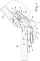
- the reference numeral 1 generally designates a snap-acting hinge with damped closure and opening angle of more than 90°.
- the hinge 1 comprises a first articulated quadrilateral 2 and a second articulated quadrilateral 3 arranged in series, which have a first lever 4 and a second lever 5 in common and are provided with respective base elements constituted by a plate 6 for coupling to a fixed element 100 and by a plate 8 for fixing to a movable element 101.
- the coupling plate 6 is connected in a lower region to the upper element that defines the compartment of the cupboard, and the fixing plate 8 is connected internally to the door leaf that closes the same compartment in a front region.
- the connection can occur, for example, with conventional screws or other threaded elements.
- the fixing plate 8 has different arrangements with respect to the coupling plate 6, which are mutually angularly spaced apart by an angle of more than 90°, corresponding to the so-called opening angle of the hinge 1.
- the hinge 1 comprises first elastic means 12 for holding the open configuration, which are associated with the first quadrilateral 2, second elastic means 13 for holding the closed configuration, which are associated with the second quadrilateral 3 and damping means 14 that act in the transition from the open configuration to the closed configuration and which are interposed between the first lever 4 and the fixing plate 8.
- the first quadrilateral 2 is constituted by the coupling plate 6, by a segment of the first lever 4, by a segment of the second lever 5 and by a first arm 15, which are mutually articulated about respective parallel pivots.
- the reference numerals 16, 17, 18 and 19 designate, respectively, the hinging pivot between the coupling plate 6 and the first lever 4, between the first lever 4 and the second lever 5, between the second lever 5 and the first arm 15 and between that first arm and the coupling plate 6.
- the second quadrilateral 3 is constituted by the fixing plate 8, by a segment of the second lever 5, by a segment of the first lever 4 and by a second arm 20, which are mutually articulated about respective parallel pivots.
- the reference numerals 21, 22 and 23 designate, respectively, the pivot between the fixing plate 8 and the second lever 5, between the first lever 4 and the second arm 20 and between the second arm and the fixing plate 8, the pivot 17 hinging between the first lever and the second lever being common to the first quadrilateral 2.
- the first elastic means 12 comprise at least one first compression spring 24 that acts between the first arm 15 and the second lever 5.
- the first arm 15 is substantially U-shaped, being provided with a pair of sides that are connected by a crossmember arranged at the pivot 19, and the first spring 24 is accommodated in the recess defined between the aforementioned sides, resting on the crossmember of that same first arm.
- the second lever 5 is integral with a supporting element 25 that is hinged on the pivots 17 and 18 and which supports a pivot 26 that protrudes between the aforementioned sides of the first arm 15, on which the first spring 24 rests in rotation.
- the second elastic means 13 comprise at least one second compression spring 27 that acts between the fixing plate 8 and the second arm 20.
- the fixing plate 8 in fact, is contoured so as to define a pair of wings that protrude beyond the pivot 23 and support an additional pivot 28, on which the second spring 27 rests in rotation.
- the second arm 20 is also substantially U-shaped, being provided with a pair of sides that are connected by a crossmember arranged at the pivot 22, and the second spring 27 is accommodated in the recess defined between the aforementioned sides resting on the crossmember of said second arm.
- the hinge 1 comprises at least one bracket 29 for connecting the damping means 14 to the fixing plate 8, which is substantially L-shaped and is constituted by a first portion and by a second portion which are mutually connected.
- the first portion of the bracket 29 is hinged to the fixing plate 8 at a first pivot 30 which, preferably, coincides with the pivot 21. Furthermore, the connecting region between the two portions of the bracket 29 is hinged to the second lever 5 about a second pivot 31. Finally, the second portion of the bracket 29 protrudes with respect to the second lever 5 toward the first quadrilateral 2 and carries a third pivot 32 about which the damping means 14 are hinged.
- the second lever 5 is constituted by two parallel wings connected by stiffening bridges, between which the brackets 29 are interposed.
- the hinge 1 comprises at least one rod 33 for connecting the damping means 14 to the first lever 4, which is articulated about the pivots 16 and 17 for hinging that first lever, respectively, to the coupling plate 6 and to the second lever 5.
- the rod 33 comprises a portion that protrudes with respect to the pivot 17 toward the second quadrilateral 3 which carries a fourth pivot 34 about which the damping means 14 are articulated.
- the first lever 4 is constituted by two parallel wings connected by stiffening bridges, between which the rods 33 are interposed.
- the damping means 14 comprise a piston (not shown in the figures) that can slide within a hollow body 35 and it is associated with a stem 36 that protrudes from that same body.
- the stem 36 is hinged to the third pivot 32 and the hollow body 35 is hinged about the fourth pivot 34.
- the hinge according to the invention makes it possible to integrate, on hinges that have an opening angle of more than 90°, the three functions of holding the open configuration by virtue of the action of the first elastic means, of holding the closed configuration by virtue of the action of the second elastic means, and of damped closure (also known as "soft-close") by virtue of the damping means.
- the hinge according to the invention does not present encumbrances outside the quadrilaterals on the side directed toward the user in use.
Landscapes
- Engineering & Computer Science (AREA)
- Mechanical Engineering (AREA)
- Hinges (AREA)
- Closures For Containers (AREA)
- Pivots And Pivotal Connections (AREA)
- Supports For Pipes And Cables (AREA)
Claims (11)
- Ein Schnappscharnier (1) mit gedämpftem Schließ- und Öffnungswinkel von mehr als 90°,
das Folgendes umfasst:ein erstes gelenkiges Rechteck (2) und ein zweites gelenkiges Rechteck (3), die einen ersten Hebel und einen zweiten Hebel (4, 5) gemeinsam haben und mit entsprechenden Grundelementen ausgestattet sind, bestehend aus einer Platte (6) zur Kopplung mit einem festen Element (100) und einer Platte (8) zur Befestigung an einem beweglichen Element (101),wobei das Scharnier (1) beweglich ist zwischen einer offenen Anordnung und einer geschlossenen Anordnung, in welcher die Befestigungsplatte (8) verschiedene Anordnungen mit Bezug auf die Kopplungsplatte (6) hat, die winklig in einem Winkel von mehr als 90° beabstandet sind;erste elastische Mittel (12) zum Halten der offenen Anordnung, die mit dem ersten Rechteck (2) verbunden sind;zweite elastische Mittel (13) zum Halten der geschlossenen Anordnung, die mit dem zweiten Rechteck (3) verbunden sind;Dämpfungsmittel (14), die beim Übergang von der offenen Anordnung in die geschlossene Anordnung wirken und zwischen dem ersten Hebel (4) und der Befestigungsplatte (8) angebracht sind; wobei das Scharnier dadurch gekennzeichnet ist, dass es weiter Folgendes umfasst:mindestens eine Stange (33) zum Verbinden der Dämpfungsmittel (14) mit dem ersten Hebel (4), wobei die Stange (33) drehgelenkig um Drehzapfen (16, 17) zur gelenkigen Verbindung des ersten Hebels (4) mit der Kopplungsplatte (6) und mit dem zweiten Hebel (5) angeschlossen und weiter mit einem Gelenkzapfen (34) für den gelenkigen Anschluss der Dämpfungsmittel (14) verbunden ist. - Das Scharnier (1) gemäß Anspruch 1, dadurch gekennzeichnet, dass es mindestens einen Arm (29) zum Verbinden der Dämpfungsmittel (14) mit der Befestigungsplatte (8) umfasst, der im Wesentlichen L-förmig ist und aus einem ersten Abschnitt und einem zweiten Abschnitt besteht, die miteinander verbunden sind;
wobei der erste Abschnitt mit der Befestigungsplatte (8) um einen ersten Drehzapfen (30) gelenkig verbunden ist, der Verbindungsbereich zwischen den Abschnitten drehgelenkig um einen zweiten Drehzapfen (31) mit dem zweiten Hebel (5) verbunden ist und der zweite Abschnitt mit den Dämpfungsmitteln (14) drehgelenkig um einen dritten Drehzapfen (32) verbunden ist. - Das Scharnier (1) gemäß Anspruch 2, dadurch gekennzeichnet, dass der dritte Drehzapfen (32) angeordnet ist, um im Verhältnis zu dem zweiten Hebel (5) zu dem ersten Viereck (2) hin vorzustehen.
- Das Scharnier (1) gemäß Anspruch 2, dadurch gekennzeichnet, dass der erste Drehzapfen (30) mit dem Drehzapfen (21) zusammenfällt, um den zweiten Hebel (5) drehgelenkig mit der Befestigungsplatte (8) zu verbinden.
- Das Scharnier (1) gemäß Anspruch 1 oder 2, dadurch gekennzeichnet, dass der Gelenkzapfen ein vierter Drehzapfen (34) ist, der angeordnet ist, um im Verhältnis zu dem Drehzapfen (17) vorzustehen, um den ersten und den zweiten Hebel (4, 5) drehgelenkig zu dem zweiten Viereck (3) hin aufzuhängen.
- Das Scharnier (1) gemäß Anspruch 1, dadurch gekennzeichnet, dass die Dämpfungsmittel (14) einen Kolben umfassen, der innerhalb eines Hohlkörpers (35) gleiten kann und mit einem Schaft (36) verbunden ist, der von dem Körper vorsteht.
- Das Scharnier (1) gemäß den Ansprüchen 2 und 6, dadurch gekennzeichnet, dass der Schaft (36) drehgelenkig um den dritten Drehzapfen (32) angeschlossen ist und der Hohlkörper (35) drehgelenkig um den vierten Drehzapfen (34) angeschlossen ist.
- Das Scharnier (1) gemäß Anspruch 1, dadurch gekennzeichnet, dass die ersten elastischen Mittel (12) mindestens eine erste Druckfeder (24) umfassen, die zwischen dem zweiten Hebel (5) und einem ersten Arm (15) des ersten Vierecks (2) wirkt, der zwischen der Kopplungsplatte (6) und dem zweiten Hebel angeordnet ist.
- Das Scharnier (1) gemäß Anspruch 1, dadurch gekennzeichnet, dass die zweiten elastischen Mittel (13) mindestens eine zweite Druckfeder (27) umfassen, die zwischen der Befestigungsplatte (8) und einem zweiten Arm (20) des zweiten Vierecks (3) wirkt, der an die Feder angrenzt.
- Das Scharnier (1) gemäß Anspruch 2, dadurch gekennzeichnet, dass der zweite Abschnitt des Arms (29) im Verhältnis zu dem zweiten Hebel (5) zu dem ersten Viereck (2) hin vorsteht und den dritten Drehzapfen (32) trägt, um welchen die Dämpfungsmittel (14) drehgelenkig angeschlossen sind.
- Das Scharnier gemäß Anspruch 1, dadurch gekennzeichnet, dass die mindestens eine Stange (33) einen Abschnitt umfasst, der mit Bezug auf den Drehzapfen (17) zum zweiten Viereck (3) hin vorsteht und den Gelenkzapfen (34) trägt, um welchen die Dämpfungsmittel (14) gelenkig angeschlossen sind.
Priority Applications (2)
| Application Number | Priority Date | Filing Date | Title |
|---|---|---|---|
| SI201731480T SI4112857T1 (sl) | 2016-10-18 | 2017-10-13 | Zaskočni tečaj z dušenim zapiranjem in kotom odpiranja večjim od 90 stopinj |
| EP23206681.1A EP4293186A3 (de) | 2016-10-18 | 2017-10-13 | Schnappscharnier mit gedämpftem schliess- und öffnungswinkel über 90 ° |
Applications Claiming Priority (2)
| Application Number | Priority Date | Filing Date | Title |
|---|---|---|---|
| IT102016000104173A IT201600104173A1 (it) | 2016-10-18 | 2016-10-18 | Cerniera a scatto con chiusura ammortizzata e angolo di apertura maggiore di 90° |
| EP17196411.7A EP3312372B1 (de) | 2016-10-18 | 2017-10-13 | Scharnier mit schnappbetätigung mit gedämpftem schliess- und öffnungswinkel von mehr als 90° |
Related Parent Applications (2)
| Application Number | Title | Priority Date | Filing Date |
|---|---|---|---|
| EP17196411.7A Division EP3312372B1 (de) | 2016-10-18 | 2017-10-13 | Scharnier mit schnappbetätigung mit gedämpftem schliess- und öffnungswinkel von mehr als 90° |
| EP17196411.7A Division-Into EP3312372B1 (de) | 2016-10-18 | 2017-10-13 | Scharnier mit schnappbetätigung mit gedämpftem schliess- und öffnungswinkel von mehr als 90° |
Related Child Applications (1)
| Application Number | Title | Priority Date | Filing Date |
|---|---|---|---|
| EP23206681.1A Division EP4293186A3 (de) | 2016-10-18 | 2017-10-13 | Schnappscharnier mit gedämpftem schliess- und öffnungswinkel über 90 ° |
Publications (2)
| Publication Number | Publication Date |
|---|---|
| EP4112857A1 EP4112857A1 (de) | 2023-01-04 |
| EP4112857B1 true EP4112857B1 (de) | 2023-11-01 |
Family
ID=58159374
Family Applications (3)
| Application Number | Title | Priority Date | Filing Date |
|---|---|---|---|
| EP17196411.7A Active EP3312372B1 (de) | 2016-10-18 | 2017-10-13 | Scharnier mit schnappbetätigung mit gedämpftem schliess- und öffnungswinkel von mehr als 90° |
| EP23206681.1A Pending EP4293186A3 (de) | 2016-10-18 | 2017-10-13 | Schnappscharnier mit gedämpftem schliess- und öffnungswinkel über 90 ° |
| EP22188428.1A Active EP4112857B1 (de) | 2016-10-18 | 2017-10-13 | Scharnier mit schnappbetätigung mit gedämpftem schliess- und öffnungswinkel von mehr als 90° |
Family Applications Before (2)
| Application Number | Title | Priority Date | Filing Date |
|---|---|---|---|
| EP17196411.7A Active EP3312372B1 (de) | 2016-10-18 | 2017-10-13 | Scharnier mit schnappbetätigung mit gedämpftem schliess- und öffnungswinkel von mehr als 90° |
| EP23206681.1A Pending EP4293186A3 (de) | 2016-10-18 | 2017-10-13 | Schnappscharnier mit gedämpftem schliess- und öffnungswinkel über 90 ° |
Country Status (11)
| Country | Link |
|---|---|
| US (1) | US10669760B2 (de) |
| EP (3) | EP3312372B1 (de) |
| CN (1) | CN107956349B (de) |
| AU (1) | AU2017248443B2 (de) |
| DK (1) | DK3312372T3 (de) |
| ES (2) | ES2951641T3 (de) |
| FI (2) | FI3312372T3 (de) |
| HU (2) | HUE065708T2 (de) |
| IT (1) | IT201600104173A1 (de) |
| PL (1) | PL3312372T3 (de) |
| SI (2) | SI4112857T1 (de) |
Families Citing this family (13)
| Publication number | Priority date | Publication date | Assignee | Title |
|---|---|---|---|---|
| IT201600104173A1 (it) | 2016-10-18 | 2018-04-18 | D G N S R L | Cerniera a scatto con chiusura ammortizzata e angolo di apertura maggiore di 90° |
| DE102016123498A1 (de) * | 2016-12-05 | 2018-06-07 | Hettich-Oni Gmbh & Co. Kg | Mehrgelenkscharnier |
| US10619659B2 (en) | 2017-08-03 | 2020-04-14 | U.S. Farathane Corporation | Closure assembly with collapsible crush barbs configured within a recess cavity defining edge of a first piece for engagement by a projection of a second piece when press fit within the recess cavity in order to engage the pieces together |
| US10643422B2 (en) * | 2017-09-28 | 2020-05-05 | Aristocrat Technologies Australia Pty Limited | Articulating hinge assembly for securing an access door on a gaming machine cabinet |
| JP2019105125A (ja) * | 2017-12-14 | 2019-06-27 | 三星電子株式会社Samsung Electronics Co.,Ltd. | ヒンジ、収納装置及び冷蔵庫 |
| JP6951588B2 (ja) * | 2019-05-16 | 2021-10-20 | スガツネ工業株式会社 | ヒンジ装置 |
| DE102019113335A1 (de) * | 2019-05-20 | 2020-11-26 | Samet Kalip Ve Maden Esya San. Ve Tic. A.S. | Möbelbeschlag |
| EP3741943A1 (de) | 2019-05-23 | 2020-11-25 | D.G.N. S.R.L. | Scharnier mit gedämpfter schliessung |
| GB2602285A (en) * | 2020-12-22 | 2022-06-29 | Titus D O O Dekani | Hinge Assembly |
| IT202100012311A1 (it) | 2021-05-13 | 2022-11-13 | D G N S R L | Cerniera a scatto ammortizzata e regolabile. |
| CN115898179B (zh) * | 2021-07-16 | 2025-09-09 | 箭牌家居集团股份有限公司 | 一种缓冲安全自动关门合页 |
| KR20230102883A (ko) * | 2021-12-30 | 2023-07-07 | 현대자동차주식회사 | 차량용 도어 힌지 장치 |
| WO2026027187A1 (en) * | 2024-07-31 | 2026-02-05 | D.G.N. S.R.L. | Hinge for furniture optimized for opening |
Family Cites Families (28)
| Publication number | Priority date | Publication date | Assignee | Title |
|---|---|---|---|---|
| IT217648Z2 (it) * | 1989-07-28 | 1992-01-07 | T G N Spa | Cerniera per mobili. con basi non incassate |
| IT1269279B (it) * | 1994-12-16 | 1997-03-26 | Tgn Spa | Cerniera a scatto per mobili perfezionata |
| DE29709806U1 (de) * | 1997-04-30 | 1997-07-31 | Arturo Salice S.P.A., Novedrate, Como | Weitwinkelscharnier |
| ATE496193T1 (de) * | 1997-08-11 | 2011-02-15 | Manfred Frank Patent Holdings Ltd | Schaukasten und dafür geeignete scharniere |
| JP3392063B2 (ja) * | 1998-09-29 | 2003-03-31 | スガツネ工業株式会社 | 安全用遮蔽板体付きヒンジ |
| IT1304909B1 (it) * | 1998-10-13 | 2001-04-05 | Tgn S P A | Cerniera a scatto per il sostegno di elementi piastriformi dichiusura. |
| IT250650Y1 (it) * | 2000-03-31 | 2003-09-24 | T G N Spa | Cerniera a scatto perfezionata per il sostegno di elementipiastriformi di chiusura. |
| ITMO20030070A1 (it) * | 2003-03-14 | 2004-09-15 | Arrigo Zetti | Cerniera a scatto perfezionata per elementi di chiusura di vani e simili. |
| US7197790B1 (en) * | 2004-08-18 | 2007-04-03 | Pe Marine Designz, Ltd | Hinge including a gas strut |
| ITMO20040288A1 (it) * | 2004-10-29 | 2005-01-29 | Tgn Spa | ''cerniera a scatto perfezionata per il sostegno di elementi di chiusura''. |
| ITMO20050007A1 (it) * | 2005-01-18 | 2006-07-19 | Arrigo Zetti | Cerniera a scatto per il sostengo di elementi di chiusura. |
| ITMO20050156A1 (it) * | 2005-06-21 | 2006-12-22 | Tgn Spa | Cerniera a scatto per il sostegno di un elemento di chiusura. |
| ITMO20050171A1 (it) * | 2005-07-07 | 2007-01-08 | Tgn Spa | ''cerniera a scatto perfezionata per il sostegno di un elemento di chiusura''. |
| US7350273B1 (en) * | 2005-10-07 | 2008-04-01 | Reading Truck Body, Inc. | Vehicle body hinge |
| ITMI20062232A1 (it) * | 2006-11-22 | 2008-05-23 | Agostino Ferrari Spa | Cerniera con ridotto ingombro per ante a movimento verticale |
| DE202007004621U1 (de) * | 2007-03-29 | 2008-08-07 | Hettich-Oni Gmbh & Co. Kg | Mehrgelenkscharnier |
| ITMO20080087A1 (it) * | 2008-03-27 | 2009-09-28 | Daniele Zetti | Cerniera a scatto perfezionata per il sostegno di un elemento di chiusura |
| AT506756B1 (de) * | 2008-04-16 | 2013-03-15 | Grass Gmbh & Co Kg | Möbelscharnier |
| CN201605928U (zh) * | 2009-12-28 | 2010-10-13 | 佛山市顺德区奇力电器实业有限公司 | 一种家具用阻尼铰链 |
| US20130239363A1 (en) * | 2010-10-14 | 2013-09-19 | Ertaç Çapur | Slow-Down Mechanism Placed in Furniture Hinge |
| DE202010015091U1 (de) * | 2010-11-04 | 2012-02-06 | Grass Gmbh | Möbelbeschlag und Möbel |
| TWM429753U (en) * | 2011-12-16 | 2012-05-21 | Hong Jeu Ind Co Ltd | Improvement of hinge structure |
| US9441407B2 (en) * | 2012-10-15 | 2016-09-13 | D.G.N. S.R.L. | Snap hinge with damped closing |
| ITMO20130025A1 (it) * | 2013-02-05 | 2014-08-06 | D G N S R L | Cerniera a scatto regolabile. |
| US10081975B2 (en) * | 2014-01-31 | 2018-09-25 | Hardware Resources, Inc. | Low profile adjustable soft close hinge apparatus |
| US9169681B2 (en) * | 2014-01-31 | 2015-10-27 | Hardware Resources, Inc. | Low profile adjustable soft close hinge apparatus |
| AU2015202678B2 (en) * | 2014-05-23 | 2019-08-22 | D.G.N. S.R.L. | Snap hinge with damped closing |
| IT201600104173A1 (it) | 2016-10-18 | 2018-04-18 | D G N S R L | Cerniera a scatto con chiusura ammortizzata e angolo di apertura maggiore di 90° |
-
2016
- 2016-10-18 IT IT102016000104173A patent/IT201600104173A1/it unknown
-
2017
- 2017-10-13 HU HUE22188428A patent/HUE065708T2/hu unknown
- 2017-10-13 EP EP17196411.7A patent/EP3312372B1/de active Active
- 2017-10-13 PL PL17196411.7T patent/PL3312372T3/pl unknown
- 2017-10-13 EP EP23206681.1A patent/EP4293186A3/de active Pending
- 2017-10-13 FI FIEP17196411.7T patent/FI3312372T3/fi active
- 2017-10-13 ES ES17196411T patent/ES2951641T3/es active Active
- 2017-10-13 HU HUE17196411A patent/HUE063029T2/hu unknown
- 2017-10-13 SI SI201731480T patent/SI4112857T1/sl unknown
- 2017-10-13 FI FIEP22188428.1T patent/FI4112857T3/fi active
- 2017-10-13 DK DK17196411.7T patent/DK3312372T3/da active
- 2017-10-13 ES ES22188428T patent/ES2970787T3/es active Active
- 2017-10-13 EP EP22188428.1A patent/EP4112857B1/de active Active
- 2017-10-13 SI SI201731390T patent/SI3312372T1/sl unknown
- 2017-10-17 US US15/785,797 patent/US10669760B2/en active Active
- 2017-10-17 CN CN201710969468.5A patent/CN107956349B/zh active Active
- 2017-10-17 AU AU2017248443A patent/AU2017248443B2/en active Active
Also Published As
| Publication number | Publication date |
|---|---|
| AU2017248443A1 (en) | 2018-05-10 |
| EP4112857A1 (de) | 2023-01-04 |
| CN107956349A (zh) | 2018-04-24 |
| EP3312372B1 (de) | 2023-05-17 |
| ES2970787T3 (es) | 2024-05-30 |
| ES2951641T3 (es) | 2023-10-24 |
| HUE065708T2 (hu) | 2024-06-28 |
| EP4293186A3 (de) | 2024-03-13 |
| FI3312372T3 (fi) | 2023-08-09 |
| FI4112857T3 (fi) | 2024-01-25 |
| EP3312372A1 (de) | 2018-04-25 |
| AU2017248443B2 (en) | 2020-09-24 |
| US20180106088A1 (en) | 2018-04-19 |
| HUE063029T2 (hu) | 2023-12-28 |
| US10669760B2 (en) | 2020-06-02 |
| IT201600104173A1 (it) | 2018-04-18 |
| SI4112857T1 (sl) | 2024-04-30 |
| DK3312372T3 (da) | 2023-08-07 |
| CN107956349B (zh) | 2021-08-06 |
| PL3312372T3 (pl) | 2023-10-02 |
| SI3312372T1 (sl) | 2023-10-30 |
| EP4293186A2 (de) | 2023-12-20 |
Similar Documents
| Publication | Publication Date | Title |
|---|---|---|
| EP4112857B1 (de) | Scharnier mit schnappbetätigung mit gedämpftem schliess- und öffnungswinkel von mehr als 90° | |
| EP2947246B1 (de) | Schnappscharnier mit gedämpftem verschliessen | |
| EP3309336B1 (de) | Schnappscharnier mit gedämpftem verschliessen | |
| US11377889B2 (en) | Hinge with damped closing | |
| EP1736627B1 (de) | Federscharnier zum Tragen von Schliesselemente | |
| US20240279971A1 (en) | Adjustable damped snap-acting hinge | |
| US7497532B2 (en) | Carcass member with flap | |
| US20090133218A1 (en) | Snap hinge for furniture | |
| EP2615234A1 (de) | Scharnier mit Schnappöffnungs- und -schließbewegung | |
| EP3115531B1 (de) | Doppelgelenkiges vierseitiges scharnier mit dämpfer | |
| WO2026027187A1 (en) | Hinge for furniture optimized for opening | |
| EP3990731A1 (de) | Möbelscharnier | |
| WO2011158097A1 (en) | Hinge for wings, particularly for wings pivoting around a horizontal axis | |
| HK1073235B (en) | A carcass member with flap |
Legal Events
| Date | Code | Title | Description |
|---|---|---|---|
| PUAI | Public reference made under article 153(3) epc to a published international application that has entered the european phase |
Free format text: ORIGINAL CODE: 0009012 |
|
| STAA | Information on the status of an ep patent application or granted ep patent |
Free format text: STATUS: THE APPLICATION HAS BEEN PUBLISHED |
|
| AC | Divisional application: reference to earlier application |
Ref document number: 3312372 Country of ref document: EP Kind code of ref document: P |
|
| AK | Designated contracting states |
Kind code of ref document: A1 Designated state(s): AL AT BE BG CH CY CZ DE DK EE ES FI FR GB GR HR HU IE IS IT LI LT LU LV MC MK MT NL NO PL PT RO RS SE SI SK SM TR |
|
| STAA | Information on the status of an ep patent application or granted ep patent |
Free format text: STATUS: REQUEST FOR EXAMINATION WAS MADE |
|
| 17P | Request for examination filed |
Effective date: 20230315 |
|
| RBV | Designated contracting states (corrected) |
Designated state(s): AL AT BE BG CH CY CZ DE DK EE ES FI FR GB GR HR HU IE IS IT LI LT LU LV MC MK MT NL NO PL PT RO RS SE SI SK SM TR |
|
| GRAP | Despatch of communication of intention to grant a patent |
Free format text: ORIGINAL CODE: EPIDOSNIGR1 |
|
| STAA | Information on the status of an ep patent application or granted ep patent |
Free format text: STATUS: GRANT OF PATENT IS INTENDED |
|
| INTG | Intention to grant announced |
Effective date: 20230503 |
|
| RIN1 | Information on inventor provided before grant (corrected) |
Inventor name: ZETTI, DANIELE |
|
| P01 | Opt-out of the competence of the unified patent court (upc) registered |
Effective date: 20230527 |
|
| GRAS | Grant fee paid |
Free format text: ORIGINAL CODE: EPIDOSNIGR3 |
|
| GRAA | (expected) grant |
Free format text: ORIGINAL CODE: 0009210 |
|
| STAA | Information on the status of an ep patent application or granted ep patent |
Free format text: STATUS: THE PATENT HAS BEEN GRANTED |
|
| AC | Divisional application: reference to earlier application |
Ref document number: 3312372 Country of ref document: EP Kind code of ref document: P |
|
| AK | Designated contracting states |
Kind code of ref document: B1 Designated state(s): AL AT BE BG CH CY CZ DE DK EE ES FI FR GB GR HR HU IE IS IT LI LT LU LV MC MK MT NL NO PL PT RO RS SE SI SK SM TR |
|
| REG | Reference to a national code |
Ref country code: GB Ref legal event code: FG4D |
|
| REG | Reference to a national code |
Ref country code: CH Ref legal event code: EP |
|
| REG | Reference to a national code |
Ref country code: IE Ref legal event code: FG4D |
|
| REG | Reference to a national code |
Ref country code: DE Ref legal event code: R096 Ref document number: 602017076221 Country of ref document: DE |
|
| REG | Reference to a national code |
Ref country code: FI Ref legal event code: FGE |
|
| REG | Reference to a national code |
Ref country code: NL Ref legal event code: FP |
|
| REG | Reference to a national code |
Ref country code: SE Ref legal event code: TRGR |
|
| REG | Reference to a national code |
Ref country code: LT Ref legal event code: MG9D |
|
| PG25 | Lapsed in a contracting state [announced via postgrant information from national office to epo] |
Ref country code: IS Free format text: LAPSE BECAUSE OF FAILURE TO SUBMIT A TRANSLATION OF THE DESCRIPTION OR TO PAY THE FEE WITHIN THE PRESCRIBED TIME-LIMIT Effective date: 20240301 |
|
| PG25 | Lapsed in a contracting state [announced via postgrant information from national office to epo] |
Ref country code: LT Free format text: LAPSE BECAUSE OF FAILURE TO SUBMIT A TRANSLATION OF THE DESCRIPTION OR TO PAY THE FEE WITHIN THE PRESCRIBED TIME-LIMIT Effective date: 20231101 |
|
| REG | Reference to a national code |
Ref country code: AT Ref legal event code: MK05 Ref document number: 1627405 Country of ref document: AT Kind code of ref document: T Effective date: 20231101 |
|
| PG25 | Lapsed in a contracting state [announced via postgrant information from national office to epo] |
Ref country code: AT Free format text: LAPSE BECAUSE OF FAILURE TO SUBMIT A TRANSLATION OF THE DESCRIPTION OR TO PAY THE FEE WITHIN THE PRESCRIBED TIME-LIMIT Effective date: 20231101 |
|
| PG25 | Lapsed in a contracting state [announced via postgrant information from national office to epo] |
Ref country code: LT Free format text: LAPSE BECAUSE OF FAILURE TO SUBMIT A TRANSLATION OF THE DESCRIPTION OR TO PAY THE FEE WITHIN THE PRESCRIBED TIME-LIMIT Effective date: 20231101 Ref country code: IS Free format text: LAPSE BECAUSE OF FAILURE TO SUBMIT A TRANSLATION OF THE DESCRIPTION OR TO PAY THE FEE WITHIN THE PRESCRIBED TIME-LIMIT Effective date: 20240301 Ref country code: BG Free format text: LAPSE BECAUSE OF FAILURE TO SUBMIT A TRANSLATION OF THE DESCRIPTION OR TO PAY THE FEE WITHIN THE PRESCRIBED TIME-LIMIT Effective date: 20240201 Ref country code: AT Free format text: LAPSE BECAUSE OF FAILURE TO SUBMIT A TRANSLATION OF THE DESCRIPTION OR TO PAY THE FEE WITHIN THE PRESCRIBED TIME-LIMIT Effective date: 20231101 Ref country code: PT Free format text: LAPSE BECAUSE OF FAILURE TO SUBMIT A TRANSLATION OF THE DESCRIPTION OR TO PAY THE FEE WITHIN THE PRESCRIBED TIME-LIMIT Effective date: 20240301 |
|
| REG | Reference to a national code |
Ref country code: ES Ref legal event code: FG2A Ref document number: 2970787 Country of ref document: ES Kind code of ref document: T3 Effective date: 20240530 |
|
| PG25 | Lapsed in a contracting state [announced via postgrant information from national office to epo] |
Ref country code: RS Free format text: LAPSE BECAUSE OF FAILURE TO SUBMIT A TRANSLATION OF THE DESCRIPTION OR TO PAY THE FEE WITHIN THE PRESCRIBED TIME-LIMIT Effective date: 20231101 Ref country code: PL Free format text: LAPSE BECAUSE OF FAILURE TO SUBMIT A TRANSLATION OF THE DESCRIPTION OR TO PAY THE FEE WITHIN THE PRESCRIBED TIME-LIMIT Effective date: 20231101 Ref country code: LV Free format text: LAPSE BECAUSE OF FAILURE TO SUBMIT A TRANSLATION OF THE DESCRIPTION OR TO PAY THE FEE WITHIN THE PRESCRIBED TIME-LIMIT Effective date: 20231101 Ref country code: HR Free format text: LAPSE BECAUSE OF FAILURE TO SUBMIT A TRANSLATION OF THE DESCRIPTION OR TO PAY THE FEE WITHIN THE PRESCRIBED TIME-LIMIT Effective date: 20231101 |
|
| REG | Reference to a national code |
Ref country code: HU Ref legal event code: AG4A Ref document number: E065708 Country of ref document: HU |
|
| PG25 | Lapsed in a contracting state [announced via postgrant information from national office to epo] |
Ref country code: DK Free format text: LAPSE BECAUSE OF FAILURE TO SUBMIT A TRANSLATION OF THE DESCRIPTION OR TO PAY THE FEE WITHIN THE PRESCRIBED TIME-LIMIT Effective date: 20231101 |
|
| PG25 | Lapsed in a contracting state [announced via postgrant information from national office to epo] |
Ref country code: CZ Free format text: LAPSE BECAUSE OF FAILURE TO SUBMIT A TRANSLATION OF THE DESCRIPTION OR TO PAY THE FEE WITHIN THE PRESCRIBED TIME-LIMIT Effective date: 20231101 |
|
| PG25 | Lapsed in a contracting state [announced via postgrant information from national office to epo] |
Ref country code: SK Free format text: LAPSE BECAUSE OF FAILURE TO SUBMIT A TRANSLATION OF THE DESCRIPTION OR TO PAY THE FEE WITHIN THE PRESCRIBED TIME-LIMIT Effective date: 20231101 |
|
| PG25 | Lapsed in a contracting state [announced via postgrant information from national office to epo] |
Ref country code: SM Free format text: LAPSE BECAUSE OF FAILURE TO SUBMIT A TRANSLATION OF THE DESCRIPTION OR TO PAY THE FEE WITHIN THE PRESCRIBED TIME-LIMIT Effective date: 20231101 Ref country code: SK Free format text: LAPSE BECAUSE OF FAILURE TO SUBMIT A TRANSLATION OF THE DESCRIPTION OR TO PAY THE FEE WITHIN THE PRESCRIBED TIME-LIMIT Effective date: 20231101 Ref country code: EE Free format text: LAPSE BECAUSE OF FAILURE TO SUBMIT A TRANSLATION OF THE DESCRIPTION OR TO PAY THE FEE WITHIN THE PRESCRIBED TIME-LIMIT Effective date: 20231101 Ref country code: DK Free format text: LAPSE BECAUSE OF FAILURE TO SUBMIT A TRANSLATION OF THE DESCRIPTION OR TO PAY THE FEE WITHIN THE PRESCRIBED TIME-LIMIT Effective date: 20231101 Ref country code: CZ Free format text: LAPSE BECAUSE OF FAILURE TO SUBMIT A TRANSLATION OF THE DESCRIPTION OR TO PAY THE FEE WITHIN THE PRESCRIBED TIME-LIMIT Effective date: 20231101 |
|
| REG | Reference to a national code |
Ref country code: DE Ref legal event code: R097 Ref document number: 602017076221 Country of ref document: DE |
|
| PLBE | No opposition filed within time limit |
Free format text: ORIGINAL CODE: 0009261 |
|
| STAA | Information on the status of an ep patent application or granted ep patent |
Free format text: STATUS: NO OPPOSITION FILED WITHIN TIME LIMIT |
|
| 26N | No opposition filed |
Effective date: 20240802 |
|
| REG | Reference to a national code |
Ref country code: CH Ref legal event code: PL |
|
| PG25 | Lapsed in a contracting state [announced via postgrant information from national office to epo] |
Ref country code: MC Free format text: LAPSE BECAUSE OF FAILURE TO SUBMIT A TRANSLATION OF THE DESCRIPTION OR TO PAY THE FEE WITHIN THE PRESCRIBED TIME-LIMIT Effective date: 20231101 |
|
| PG25 | Lapsed in a contracting state [announced via postgrant information from national office to epo] |
Ref country code: LU Free format text: LAPSE BECAUSE OF NON-PAYMENT OF DUE FEES Effective date: 20241013 Ref country code: BE Free format text: LAPSE BECAUSE OF NON-PAYMENT OF DUE FEES Effective date: 20241031 |
|
| PG25 | Lapsed in a contracting state [announced via postgrant information from national office to epo] |
Ref country code: CH Free format text: LAPSE BECAUSE OF NON-PAYMENT OF DUE FEES Effective date: 20241031 |
|
| REG | Reference to a national code |
Ref country code: BE Ref legal event code: MM Effective date: 20241031 |
|
| PGFP | Annual fee paid to national office [announced via postgrant information from national office to epo] |
Ref country code: IT Payment date: 20250922 Year of fee payment: 9 |
|
| PG25 | Lapsed in a contracting state [announced via postgrant information from national office to epo] |
Ref country code: IE Free format text: LAPSE BECAUSE OF NON-PAYMENT OF DUE FEES Effective date: 20241013 |
|
| PGFP | Annual fee paid to national office [announced via postgrant information from national office to epo] |
Ref country code: SI Payment date: 20251003 Year of fee payment: 9 |
|
| PGFP | Annual fee paid to national office [announced via postgrant information from national office to epo] |
Ref country code: HU Payment date: 20251010 Year of fee payment: 9 |
|
| PGFP | Annual fee paid to national office [announced via postgrant information from national office to epo] |
Ref country code: NL Payment date: 20251017 Year of fee payment: 9 |
|
| PG25 | Lapsed in a contracting state [announced via postgrant information from national office to epo] |
Ref country code: RO Free format text: LAPSE BECAUSE OF FAILURE TO SUBMIT A TRANSLATION OF THE DESCRIPTION OR TO PAY THE FEE WITHIN THE PRESCRIBED TIME-LIMIT Effective date: 20231101 |
|
| PGFP | Annual fee paid to national office [announced via postgrant information from national office to epo] |
Ref country code: DE Payment date: 20251017 Year of fee payment: 9 |
|
| PGFP | Annual fee paid to national office [announced via postgrant information from national office to epo] |
Ref country code: GB Payment date: 20251016 Year of fee payment: 9 |
|
| PGFP | Annual fee paid to national office [announced via postgrant information from national office to epo] |
Ref country code: NO Payment date: 20251029 Year of fee payment: 9 |
|
| PGFP | Annual fee paid to national office [announced via postgrant information from national office to epo] |
Ref country code: FI Payment date: 20251028 Year of fee payment: 9 |
|
| PGFP | Annual fee paid to national office [announced via postgrant information from national office to epo] |
Ref country code: FR Payment date: 20251016 Year of fee payment: 9 |
|
| PGFP | Annual fee paid to national office [announced via postgrant information from national office to epo] |
Ref country code: SE Payment date: 20251029 Year of fee payment: 9 |
|
| PG25 | Lapsed in a contracting state [announced via postgrant information from national office to epo] |
Ref country code: CY Free format text: LAPSE BECAUSE OF FAILURE TO SUBMIT A TRANSLATION OF THE DESCRIPTION OR TO PAY THE FEE WITHIN THE PRESCRIBED TIME-LIMIT; INVALID AB INITIO Effective date: 20171013 |
|
| PGFP | Annual fee paid to national office [announced via postgrant information from national office to epo] |
Ref country code: ES Payment date: 20251118 Year of fee payment: 9 |