EP4116494B1 - Procédé permettant de faire fonctionner une machine à fraiser le sol - Google Patents
Procédé permettant de faire fonctionner une machine à fraiser le sol Download PDFInfo
- Publication number
- EP4116494B1 EP4116494B1 EP22181517.8A EP22181517A EP4116494B1 EP 4116494 B1 EP4116494 B1 EP 4116494B1 EP 22181517 A EP22181517 A EP 22181517A EP 4116494 B1 EP4116494 B1 EP 4116494B1
- Authority
- EP
- European Patent Office
- Prior art keywords
- milling
- milling drum
- data set
- drum
- information
- Prior art date
- Legal status (The legal status is an assumption and is not a legal conclusion. Google has not performed a legal analysis and makes no representation as to the accuracy of the status listed.)
- Active
Links
Images


Classifications
-
- E—FIXED CONSTRUCTIONS
- E01—CONSTRUCTION OF ROADS, RAILWAYS, OR BRIDGES
- E01C—CONSTRUCTION OF, OR SURFACES FOR, ROADS, SPORTS GROUNDS, OR THE LIKE; MACHINES OR AUXILIARY TOOLS FOR CONSTRUCTION OR REPAIR
- E01C23/00—Auxiliary devices or arrangements for constructing, repairing, reconditioning, or taking-up road or like surfaces
- E01C23/06—Devices or arrangements for working the finished surface; Devices for repairing or reconditioning the surface of damaged paving; Recycling in place or on the road
- E01C23/08—Devices or arrangements for working the finished surface; Devices for repairing or reconditioning the surface of damaged paving; Recycling in place or on the road for roughening or patterning; for removing the surface down to a predetermined depth high spots or material bonded to the surface, e.g. markings; for maintaining earth roads, clay courts or like surfaces by means of surface working tools, e.g. scarifiers, levelling blades
- E01C23/085—Devices or arrangements for working the finished surface; Devices for repairing or reconditioning the surface of damaged paving; Recycling in place or on the road for roughening or patterning; for removing the surface down to a predetermined depth high spots or material bonded to the surface, e.g. markings; for maintaining earth roads, clay courts or like surfaces by means of surface working tools, e.g. scarifiers, levelling blades using power-driven tools, e.g. vibratory tools
- E01C23/088—Rotary tools, e.g. milling drums
-
- E—FIXED CONSTRUCTIONS
- E01—CONSTRUCTION OF ROADS, RAILWAYS, OR BRIDGES
- E01C—CONSTRUCTION OF, OR SURFACES FOR, ROADS, SPORTS GROUNDS, OR THE LIKE; MACHINES OR AUXILIARY TOOLS FOR CONSTRUCTION OR REPAIR
- E01C21/00—Apparatus or processes for surface soil stabilisation for road building or like purposes, e.g. mixing local aggregate with binder
-
- E—FIXED CONSTRUCTIONS
- E01—CONSTRUCTION OF ROADS, RAILWAYS, OR BRIDGES
- E01C—CONSTRUCTION OF, OR SURFACES FOR, ROADS, SPORTS GROUNDS, OR THE LIKE; MACHINES OR AUXILIARY TOOLS FOR CONSTRUCTION OR REPAIR
- E01C23/00—Auxiliary devices or arrangements for constructing, repairing, reconditioning, or taking-up road or like surfaces
- E01C23/06—Devices or arrangements for working the finished surface; Devices for repairing or reconditioning the surface of damaged paving; Recycling in place or on the road
- E01C23/12—Devices or arrangements for working the finished surface; Devices for repairing or reconditioning the surface of damaged paving; Recycling in place or on the road for taking-up, tearing-up, or full-depth breaking-up paving, e.g. sett extractor
- E01C23/122—Devices or arrangements for working the finished surface; Devices for repairing or reconditioning the surface of damaged paving; Recycling in place or on the road for taking-up, tearing-up, or full-depth breaking-up paving, e.g. sett extractor with power-driven tools, e.g. oscillated hammer apparatus
- E01C23/127—Devices or arrangements for working the finished surface; Devices for repairing or reconditioning the surface of damaged paving; Recycling in place or on the road for taking-up, tearing-up, or full-depth breaking-up paving, e.g. sett extractor with power-driven tools, e.g. oscillated hammer apparatus rotary, e.g. rotary hammers
-
- E—FIXED CONSTRUCTIONS
- E21—EARTH OR ROCK DRILLING; MINING
- E21C—MINING OR QUARRYING
- E21C47/00—Machines for obtaining or the removal of materials in open-pit mines
Definitions
- the invention relates to a method for operating a ground milling machine, in particular a road milling machine, a stabilizer, a recycler, a surface miner or the like, with an exchangeable milling drum, wherein the milling drum is equipped with a plurality of milling tools, in particular round shank chisels, wherein the milling drum has a current state, wherein a control unit is provided for controlling at least one function of the ground milling machine, and wherein the milling drum has a characteristic feature or a characteristic feature is assigned to the milling drum.
- a road milling machine with a milling drum is known.
- the milling drum is equipped with a characteristic feature. This characteristic feature can be read out with a suitable reading unit.
- the characteristic feature is evaluated in a control unit so that the road milling machine recognizes which type of milling drum it is.
- Different types of milling drums are designed to carry out different work tasks.
- a so-called fine milling drum is used to To mill off part of the surface layer of a road surface. In particular, slight unevenness in the road surface can be removed. The resulting surface layer can be released for road traffic immediately.
- Another type of milling drum is used to remove a complete road surface.
- special types of milling drum are designed for different work tasks, e.g. with regard to working width, milling depth or desired milling pattern.
- control unit can specify a suitable set of machine parameters.
- the road milling machine can be operated appropriately using this set of machine parameters.
- EN 10 2015 111 249 A1 discloses a road milling machine in which the default machine parameters, material properties of the subsoil to be milled and job data can be entered. Using characteristic maps, suitable target machine parameters can be calculated from these default values. The machine operator can be shown the target machine parameters and can decide whether to set these target machine parameters on the milling machine. Alternatively, the target machine parameters can be automatically transferred to a control unit for controlling the road milling machine.
- the documents EP 2 716 816 A1 and EP 3 260 603 A1 reveal road milling machines that have sensors.
- the sensors can be used to record the milling volume milled by a road milling machine.
- road milling machines are known to have detection devices. These detection devices can be used to automatically determine the wear of the milling tools.
- the milling machines described above make it easier for the machine operator to complete the milling task. After the milling task has been completed The milling machine is transported to the next construction site, where the requirements can be met with the installed milling drum type.
- the milling drum If the milling drum is partially worn, it can continue to be used. If the milling tools are completely worn, the milling tools must be replaced. After the replacement, the milling machine can then continue to be operated on the construction site.
- This object is achieved with a method according to claim 1, wherein at least one data set containing information about the current state of the milling drum is stored in a storage unit, a characteristic feature identifying the milling drum is assigned to the data set in the storage unit, and this data set is transmitted to a processing device.
- the state of the milling drum is therefore stored.
- This state can be recorded directly, for example by measuring the milling drum.
- an optical measuring method can be used for this, which measures the milling tools with a laser scanner, for example, and compares the result with a measurement result of the milling drum in the unworn state.
- the condition is determined indirectly, for example using job data and/or material characteristics of the removed material and/or the set machine parameters that were recorded or taken into account during use of the milling tools.
- Material characteristics within the scope of the invention may be the abrasiveness and/or the hardness and/or a material type (for example asphalt or concrete) and/or a material composition and/or a temperature and/or a layer structure of the surface to be removed.
- a material type for example asphalt or concrete
- a material composition for example asphalt or concrete
- the current state can also be entered manually.
- a start state is set manually and then automatically updated during operation.
- the existing chisels on a milling drum are replaced with new or partially worn chisels.
- the operator of the ground milling machine can then manually enter the current status of these chisels and thus manually set the start status. During operation, this status is then automatically updated, as described above.
- Job data is in particular data that was or is recorded during the operation of the milling drum, for example the milled area, the milling volume and/or the milling mass of the material removed and/or the milling time.
- Possible set machine parameters within the scope of the invention are machine parameters that are or were set in a fixed or variable manner during use of the milling drum, for example the milling depth, the feed rate, the milling drum speed, the engine power transmitted to the milling drum and/or the torque transmitted to the milling drum.
- One or more of these machine parameters can be part of a machine parameter set.
- the current condition of the milling drum can be determined solely by one of the aforementioned wear components and stored in the data set.
- the current state of the milling drum can also be characterized within the scope of the invention by a tuple which comprises at least two of the aforementioned wear components and which are taken into account in the data set.
- the current state of the milling drum can also be taken into account as at least one key figure in the data set, whereby the key figure contains, for example, information about the remaining service life of the milling drum or which can be derived from the remaining service life of the milling drum. It is also conceivable that the key figure indicates a residual wear capacity.
- the key figures can represent the current condition of the milling drum and thus enable conclusions to be drawn about the work results that can be achieved with the milling drum and/or the work performance that can still be achieved by the milling drum.
- the current condition of the milling drum can also include a qualitative assessment. In particular, it can be stated whether the milling drum is still usable in principle.
- the qualitative classification can also take into account the efficiency with which the milling drum can complete a milling task or the quality of the work result that can be produced by the milling drum, for example in the form of a percentage. It is also conceivable that a large number of key figures for individual milling drum components are taken into account in the data set.
- a single key figure and/or a qualitative assessment can also be derived as an "overall wear condition" from the overall consideration of a large number of key figures.
- a data set is created according to the invention that reflects the current state of the milling drum.
- This data set is linked in the storage unit to the characteristic feature that individualizes the milling drum.
- the characteristic feature is a unique identification for an individual milling drum.
- the data set can then be transferred to a processing device.
- the processing device can be arranged on the ground milling machine, for example. It is also conceivable that the processing device is arranged spatially separate from the ground milling machine. For example, it is conceivable that the processing device is connected to the ground milling machine by wire or wirelessly, at least temporarily.
- An additional processing device may also be provided.
- the further processing device and the processing device can be combined in a common unit or it can preferably be provided that the processing device and the further processing device are arranged spatially separated from one another.
- the data set can be evaluated in the further processing device. Using the characteristic feature of the milling drum, which enables the milling drum to be clearly identified and from which the milling drum type can be determined, a computing unit determines whether this milling drum is generally suitable for an upcoming milling task. The further processing device can then determine whether this generally suitable milling drum meets certain requirements with the current state resulting from the data set.
- the further processing device can also select from a pool of milling drums that are in principle suitable for carrying out an upcoming milling task according to their milling drum type, the milling drum that is actually best suited for the upcoming task.
- the suitability of the milling drum can be determined by taking into account the current condition of the milling drums in the pool.
- One criterion for this can be, for example, that the most suitable milling drum is filtered out from the pool, for example with the additional processing equipment, with which the task at hand can be accomplished most quickly, efficiently or cost-effectively.
- the current condition of the milling drum is classified according to predefined criteria.
- a user or the other processing device can then determine whether the milling drum meets the requirements for a planned milling job.
- the further processing device determines whether the milling drum in question is sufficiently suitable for an upcoming milling task.
- the further processing device can inform the user on request which of the milling drum(s) is/are suitable for the planned milling job.
- the usability, the quality of the work result that can be produced with the milling drum and/or the efficiency of the milling drum can be determined. These parameters can be derived in particular from the stored data set containing the current state of the milling drum.
- the quality of the milling drum is assessed, it can be determined in the further processing facility, for example, which milling pattern quality can be produced with the milling drum in question.
- the milling drum in question or the milling drums in a pool can be classified into a quality scale based on the data set, or it can be determined whether the required milling pattern quality can be produced with the milling drum.
- the further processing device determines which machine parameters are required to operate the milling drum as intended with the current state of the milling drum. For example, it can be determined which drive power and/or drive torque must be applied for the intended use in order to achieve the desired work result, for example. In correlation with this, it can be determined how high the consumption of consumables (for example fuel consumption and/or coolant consumption) is for the intended use.
- consumables for example fuel consumption and/or coolant consumption
- the data set can be used to determine whether the milling drum is still fundamentally usable for the intended or planned use.
- job data is in particular data that was or is recorded during the operation of the milling drum, for example the milled area, the milling volume and/or the milling mass of the removed material and/or the milling time.
- job data can also be used, for example, a planned change to the material to be processed, for example a milling distance, a milling performance, a milling work and/or a milling work time.
- a mass or a milling volume of the material to be removed can be specified as milling work. This can lead to a required milling distance and milling depth.
- a work per time can be specified as milling performance, for example a mass to be processed per time, a volume of material to be processed per time or an area or distance to be processed per time.
- the working time can include when a specified job must be completed. It can also indicate when a good time is to change the soil processing tools, for example at the end of a shift or during a planned downtime of the soil milling machine.
- a characteristic feature within the meaning of the invention can in particular be an individualizing marking applied to the milling drum at a suitable location, for example a barcode, a sequence of numbers or letters.
- a characteristic feature can also be an identifier that is present in or on an optically or electrically readable element, for example an active or passive transponder, for example an RFID transponder or the like.
- the machine operator manually records the characteristic feature of the milling drum.
- the characteristic feature of the milling drum is read out using a reading unit.
- the reading unit can be part of the soil milling machine or can be connected to the soil milling machine via a wired or wireless line in order to transmit data.
- the reading unit is part of a separate computing unit that is designed to make wireless contact with the control unit of the ground milling machine.
- a milling drum can then be uniquely identified wirelessly via the separate computing unit.
- the separate computing unit can have the storage unit in which the characteristic feature of the milling drum is linked to the data set containing information about the milling drum.
- the data set can then be transmitted to the processing device.
- the storage unit on which the characteristic feature and the data set containing information about the current state of the milling drum are linked can preferably be arranged on the milling drum.
- the storage unit can be an electronically readable and writable medium.
- the characteristic feature and/or the data set can be read out via a suitable reading device, for example when the milling drum is changed, and transmitted directly to the processing device.
- the storage unit is designed separately from the milling drum. Accordingly, after the characteristic feature on the milling drum has been recorded (which can be done manually, for example), the data set linked to this characteristic feature and containing information about the current state of the milling drum must be transmitted from the storage unit to the processing device.
- the storage unit is designed as a database in which characteristic features and data sets are linked. Once the characteristic feature of the milling drum has been recorded, the associated data set containing information about the current state of the milling drum can now be determined and transmitted to the processing device.
- a data set about the current state of the milling drum is stored in the processing device before the start of a milling task.
- the milling tools are subject to wear.
- the state of the milling drum changes accordingly compared to the initial state.
- the change in the state of the milling drum caused by the milling task can then be assessed or determined.
- the processing device then generates a new data set from the originally stored data set of this milling drum and the change in state caused by the milling task, which then reflects the current state of the milling drum.
- This new data set therefore represents an updated data set that contains the last carried out milling task is taken into account. It therefore represents the state of the milling drum after the milling task has been carried out
- each milling task can be viewed as an individual wear event.
- the resulting change in the condition of the milling drum is offset against the condition of the milling drum before the milling task was carried out in order to determine the current condition of the milling drum.
- the floor milling machine continuously determines the change in the state of the milling drum while a milling task is being completed and that a data set is generated at the end of the milling task that contains information about the current state of the milling drum.
- This variant takes into account that the tools, which increasingly wear out during the work process, affect the machine parameters and tool wear.
- a new data set containing information about the current state of the milling drum is transmitted back to the storage device.
- a (new) data set containing information about the current state of the milling drum is available in the processing device. This new data set is then preferably transmitted to the storage device and linked to the characteristic feature of the milling drum.
- the data set containing information about the current status of the milling drum can also be regularly transmitted to the storage unit during milling operation and stored linked to the characteristic feature of the milling drum.
- the new data set can be transferred to the storage unit on the milling drum at the end of the milling task.
- the milling drum identified by the characteristic feature is assigned to a ground milling machine.
- milling data from the ground milling machine can be forwarded to the separate computing unit to determine the data set.
- a new data set containing information on the current status of the milling drum is generated based on the milling data from the ground milling machine. This is then also transmitted to the storage unit and linked to the characteristic feature of the milling drum.
- the additional processing device is provided on the separate computing unit.
- the separate computing unit can then, for example, assess whether a milling drum identified by the separate computing unit is suitable for an upcoming milling task. This result can then be transmitted to the operator by the separate computing unit.
- a machine operator has a large number of milling drums available in the workshop. The machine operator then asks whether one of the milling drums is suitable for an upcoming milling task.
- the separate computing unit determines the milling drums available on site and then gives the operator feedback on which milling drums are suitable for the upcoming milling task. The machine operator can then select a suitable milling drum and install it in the floor milling machine.
- the milling drum has an active transmitting element that transmits the characteristic feature and/or the data set to a reading unit.
- the storage location of the milling drum can be determined, for example, by the separate computing unit or a other reading unit. For example, it is then possible to determine whether a particular milling drum is on a construction site or in the workshop.
- the milling drum has a position transmitter which is designed to send a position signal, preferably at regular intervals or permanently, and that the characteristic feature and/or the data set is transmitted wirelessly by the milling drum with the position signal, wherein the position transmitter is preferably a GPS transmitter.
- the milling drum has a passive reading element that is read with a reading unit in order to record the characteristic feature and/or the data set. An operator can then use a suitable reading device to check various milling drums he has at his disposal for their suitability for a specific milling task.
- the active transmitting element is an active RFID
- the passive reading element is a passive RFID or a readable coding, in particular a barcode, a QR code or the like.
- the storage unit in which the data set is stored is part of the milling drum or part of the separate computing unit.
- the data set is/is stored in a suitable storage unit of the milling drum. Using a suitable reader, this data set can then be transferred to the processing device, which can preferably be provided on the ground milling machine. However, it is also conceivable that the data set is transmitted from the separate computing unit to the processing device, which can preferably be provided on the ground milling machine. This makes the process considerably easier.
- a particularly preferred variant of the invention is designed in such a way that during the milling operation of the floor milling machine, milling data, in particular the milling time, the milled material volume and/or the milled area, are recorded, and that this milling data or a calculation of this milling data is combined as an additional data set with the data set, preferably in the processing device; and a new data set is generated from this, which characterizes the new current state of the milling drum. In this way, the state of the milling drum is updated and tracked. It can be provided that the additional data set is combined with the data set continuously or at intervals during the milling operation. This makes it possible to track the state of the milling drum at different points in time.
- the additional data set is combined with the data set after the milling operation. Accordingly, after the milling task has been completed, the new data set, which provides information about the current status of the milling drum, can be generated and saved in the storage unit.
- the new data set is transmitted to the milling drum, the soil milling machine and/or the separate computing unit.
- At least one specified machine parameter and/or at least one material characteristic of the material to be milled and/or job data is/are recorded by means of an input unit, which can preferably be provided on the floor milling machine, and that the further processing device is designed to is to determine from the at least one specified machine parameter and/or the at least one material characteristic and/or the job data whether the milling drum is suitable for an upcoming milling task.
- the further processing device can determine whether a milling drum is fundamentally suitable for completing the required task.
- the job data can specify that the milling drum is to be used for a fine milling task, a full removal of a road surface or a partial removal of a road surface. With the appropriately selected job data, it can then be further assessed, taking the data set into account, whether this milling drum, which is fundamentally suitable, is also specifically suitable for completing a specific task.
- the job data can specify that a certain removal volume must be milled with the milling drum at a specified milling depth.
- an operator selects a processing mode by means of an input unit.
- various job data can be summarized in a processing mode.
- the operator can specify, for example, how efficiently the floor milling machine should complete the milling task.
- the processing mode can be used to select that the floor milling machine should use as little of one or more operating resources as possible (e.g. fuel, coolant) (eco mode).
- the floor milling machine should be operated with as little wear on the milling tools as possible in order to complete the milling task.
- it can be provided, for example, that the milling task should be completed in a time-optimized manner, for example as quickly as possible.
- the further processing device determines, taking into account the selected mode and the data set, whether the milling task can be completed with a milling drum.
- a The control unit of the floor milling machine depending on the selected operating mode and taking the data set into account, sets the machine parameters for operating the floor milling machine appropriately, tailored to the selected operating mode, or suggests them to the operator.
- the object of the invention is also achieved with a milling arrangement with a ground milling machine according to independent claim 21, in particular with a road milling machine, with a stabilizer, with a recycler, with a surface miner or the like, with an exchangeable milling drum, wherein the milling drum is equipped with a plurality of milling tools, wherein the milling drum has a current state, wherein a control unit is provided for controlling at least one function of the ground milling machine, and wherein the milling drum has a characteristic feature.
- At least one data set is stored in a storage unit, which contains information about the current state of the milling drum, that the characteristic feature identifying the milling drum is assigned to the data set in the storage unit, and that this data set or a calculation containing the data set is transmitted to a processing device.
- the computing units, computers or similar computer systems, the external computing unit or the ground milling machine described in this patent application can, for example, have (not shown), at least one processor, a computer-readable storage medium, a database, an input unit and an output unit.
- the input unit can be designed as a keyboard or as another user interface and enables an operator to enter instructions.
- the output unit can be designed as a display or in the form of another optical or acoustic display.
- the processor can be designed as a single controller which comprises all of the described functionality, or several controllers can be provided, over which the described functionality is divided.
- a computer-readable storage medium is to be understood as any form of non-volatile storage medium which contains a computer program product in the form of software executable by the processor, computer instructions or program modules. When executed, these can provide data or otherwise cause the computer system to implement an instruction or, as defined here, to work in a specific way. It can also be provided that more than one type of storage media are used in combination to direct software, computer instructions or program modules executable by the processor from a first storage medium in which the software, computer instructions or program modules are initially stored to the microprocessor for execution.
- the storage media as used here can be, without limitation, transmission media or data storage.
- the data storage can equally be volatile and non-volatile, removable and non-removable media.
- Transmission media may include any specific media suitable for allowing processor-executable software, computer instructions, or program modules to be read and executed by a processor. Cables, wires, fiber optics, or known wireless media may be used for this purpose without limitation.
- the processor may not constitute or require a computer system. It may be implemented separately or otherwise independently configured within a machine, such as a general purpose processor, a digital signal processor (DSP), an ASIC (Application Specific Integrated Circuit), a FPGA (Field Programmable Gate Array) or other programmable logic device, a discrete gate or transistor logic circuit, discrete hardware components, or any combination thereof designed or programmed to perform or bring about the functions described.
- DSP digital signal processor
- ASIC Application Specific Integrated Circuit
- FPGA Field Programmable Gate Array
- the general purpose processor may be a microprocessor or alternatively a microcontroller, a state machine, or a combination thereof.
- the processor may also be implemented as a combination of computing devices, for example as a combination of a DSP with a microprocessor, a plurality of microprocessors, one or more microprocessors in conjunction with a DSP core, or any other such combination.
- certain acts, operations or functions of each of the algorithms described with respect to the controller may be performed in a different order, they may be added or combined, or they may be omitted (for example, if not all of the functions described are required for execution of the algorithm).
- acts, operations or functions may be performed concurrently, for example by multi-threaded processing, interrupted processing, or by multiple processors or processor cores, or any other parallel architecture.
- Fig.1 shows a schematic representation and side view of a ground milling machine 10 in the form of a road milling machine.
- a machine frame 12 is supported by four lifting columns 13, which are height-adjustable, by chassis 11, for example crawler tracks.
- the ground milling machine 10 can be operated from a control station 14 via a control 20 arranged in the control station 14.
- a milling drum 16, which is concealed and shown in dashed lines in the illustration, is rotatably mounted in a drum housing 18.
- a conveyor device 17 is used to transport the milled material away.
- the machine frame 12 is moved over the subsoil to be machined at a feed rate entered via the control 20.
- milling tools in particular chisels, in particular round shank chisels, arranged on the rotating milling drum 16 remove the subsoil.
- the height position and the speed of the milling drum 16 can be adjusted from the control 20.
- the milling depth is adjusted via the height position of the milling drum 16.
- the height position of the milling drum 16 can be adjusted via the height-adjustable lifting columns 13 or other suitable means.
- the milling drum 16 can be adjusted via the height-adjustable lifting columns 13, as for example in the case of the Fig. 2 shown floor milling machine 10, which is designed as a stabilizer, can be adjustable in height relative to the machine frame 12.
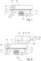
- Fig. 2 shows a schematic representation and side view of a second soil milling machine 10 in the form of a stabilizer.
- the second soil milling machine 10 is moved by means of chassis 11 designed as front and rear wheels.
- the front and rear wheels are attached to the machine frame 12 via front and rear lifting columns 13 so that the working height of the machine frame 12 and thus of the roller housing 18 can be adjusted.
- a control station 14 is attached to the machine frame 12.
- the motor 12.1 arranged within the machine frame 12 drives the milling roller 16 via a drive unit 12.
- the milling roller 16 itself is mounted in the roller housing 18, to which a front and a rear roller flap 18.1, 18.2 is assigned.
- the roller flaps 18.1, 18.2 are each adjustable via an attached hydraulic system.
- the milling drum 16 can be adjusted in height via a hydraulic height adjustment 19 along an adjustment path 19.1 shown by a double arrow.
- a hydraulic height adjustment 19 along an adjustment path 19.1 shown by a double arrow.
- the movement of a hydraulic cylinder 19.2 is transmitted to the milling drum 16 via a pivoting lever 19.3 and an adjusting rod 19.4 arranged on it.
- the milling depth can be adjusted using the height adjustment.
- Figure 3 shows a floor milling machine 10, for example a floor milling machine 10 of the Figures 1 or 2 shown in a further simplified representation.
- the ground milling machine 10 has a machine frame 12 to which four chassis 11, for example crawler tracks, are coupled via four lifting columns 13.
- chassis 11 for example crawler tracks
- lifting columns 13 In the area between the front and rear chassis 11, a milling drum 16 can be mounted in an exchangeable manner, for example in a drum housing 18.
- the soil milling machine 10 has the control unit 15. Part of this control unit 15 can be a processing device 30, or a Processing device 30.
- the processing device 30 can also be provided as a separate unit, preferably on the floor milling machine 10.
- the processing device 30 can also comprise or form a further processing device.
- processing device 30 and/or the further processing device can also be arranged separately from the ground milling machine 10.
- the milling drum 16 is stored away from the ground milling machine 10.
- the milling drum 16 has a milling drum tube.
- Milling tools can be attached to the surface of the milling drum tube in a directly or indirectly replaceable manner.
- a milling tool is connected to the surface of the milling drum tube in a directly or indirectly replaceable manner via a chisel holder.
- a milling tool can be mounted in a chisel holder in a replaceable manner and that the chisel holder can be connected to a base part in a replaceable manner.
- the base part is connected to the surface of the milling drum tube, for example welded.
- the milling drum 16 can, for example, have a position transmitter 16.3.
- This position transmitter 16.3 can, for example, be a GPS module which transmits a position signal, for example at regular intervals or permanently.
- the milling drum 16 is equipped with a characteristic feature 16.4.
- This can be contained, for example, in a storage unit 16.1.
- the characteristic feature 16.4 can be a readable code that is stored in the storage unit 16.1. It is also conceivable that the characteristic feature 16.4 is formed by a sequence of letters and/or numbers, a barcode, or a QR code or another readable code.
- the characteristic feature 16.4 can contain, or be linked to, information relating to a unique identifier of the milling drum 16 and/or information about the milling drum type and/or information about the chisel holder type and/or information about the number of milling tools installed on the milling drum 16 and/or information about the line spacing of chisels arranged in a line on the milling drum 16.
- the characteristic feature 16.4 is a fixed feature of the milling drum 16.
- the milling drum 16 can be installed with the ground milling machine 10.
- the characteristic feature 16.4 can be read out using a reading unit.
- the storage unit 16.1 is an RFID transponder in which the characteristic feature 16.4 is stored.
- the characteristic feature can be read out of the RFID transponder using an RFID reading device.
- the reading device can be part of the ground milling machine 10 or the reading device can be a separate device, for example a handset, by means of which the characteristic feature 16.4 is read out on the milling drum 16.
- Figure 4 illustrates that a data set 16.2 is stored in the storage unit 16.1.
- This data set 16.2 contains information about the current state of the milling drum 16. Accordingly, the data set 16.2 can contain the information that at least one milling tool and/or the milling drum 16 is in an unworn state or that at least one milling tool or the milling drum 16 is in a partially worn state. This information can contain a statement about the actual quantitative wear and/or information about the actual quantitative residual wear capacity of at least one milling tool and/or the milling drum 16.
- information may be encoded in the data set 16.2 which provides information on the wear condition and/or the residual wear capacity of at least one chisel holder, at least one base part, at least one ejector mounted on the milling drum and/or the milling drum tube. These are therefore variable features of the milling drum 16.
- information about the expected milling image quality can be encoded in the data set, with this coding providing information about whether a certain milling image quality or which milling image quality can be milled with the milling drum 16 in question. It is conceivable that the expected milling image quality is encoded on the basis of variable characteristics of the milling drum 16. Alternatively, a statement about the expected milling image quality can also be generated in a separate computing unit to which these variable characteristics are fed and which evaluates these variable characteristics.
- the data set 16.2 can also contain information about the efficiency and/or usability of the milling drum 16. It is conceivable that the expected efficiency or usability is coded on the basis of variable characteristics of the milling drum 16. Alternatively, a statement about the expected efficiency or usability can also be generated in a separate computing unit 40, to which these variable characteristics are sent and which evaluates these variable characteristics.
- data set 16.2 may also contain information on a fixed feature of the milling drum, such as milling drum type, number of chisels installed on the milling drum, type of chisel holder in which the milling chisels are mounted, and/or line spacing of the milling chisels on the milling drum.
- Figure 4 shows that one or more memories are provided in the processing device 30.
- a memory 31 for fixed features, a memory 32 for variable features and a memory 33 for calculated features can be provided.
- the memories 31, 32, 33 can form a single memory.
- the memory 33 for calculated features contains calculated features that result from a calculation of one or more of the fixed characteristics and/or one or more of the variable characteristics.
- one or more fixed features, one or more variable features/or one or more calculated features of a milling drum 16 can be stored in the processing device 30.
- FIG. 5 shows that the milling drum 16 is installed in the milling drum box 18 of the soil milling machine 10. Before the milling drum 16 is installed or when the milling drum 16 is installed, the storage unit 16.1 is read out.
- One or more of the information about the milling drum held in the storage unit forms the data set 16.2, which contains information about the current state of the milling drum 16.
- This data set 16.2 is transferred to the processing device 30.
- the fixed features are stored in the memory 31 for the fixed features and the variable features in the memory 32 for the variable features.
- a computing unit selects from one or more of the fixed features and one or more of the variable features that are to be calculated.
- the calculated features are stored in the memory 33 for calculated features.
- the floor milling machine 10 can be switched to milling operation.
- one or more relevant operating variables of the floor milling machine 10 are determined. For example, the operating time of the floor milling machine, the volume of milled material, the average or detailed milling depth, the average or detailed mechanical load, for example the engine power or the drive torque, the average or detailed feed, the force/or load of the milling bits on average or in detail and/or the number of overload events are recorded using suitable recording devices, for example sensors.
- the type of milled material for example asphalt or concrete, can also be recorded as a relevant operating variable and/or it can be recorded whether milling was carried out with or without loading of the milled material and/or information on the number of milling drum changes can be recorded.
- changes in the wear of the milling drum 16 or a part of the milling drum 16 are calculated in a computing unit and provided in an additional data set.
- a new data set is created in the computing unit, taking into account the data set 16.2 and the additional data set.
- This new data set is stored in the storage unit 16.1, as Figure 8
- This new data set then forms data set 16.2, which provides information about the current state of the milling drum 16.
- Figure 8 further illustrates that the milling drum 16 can be removed after completion of the milling process.
- the removed milling drum 16 now contains the data set 16.2 and is available for reuse.
- the memories 31, 32, 33 in the processing device 30 can now be deleted, for example, and/or the data contained therein can be used for other purposes.
- a separate computing unit 40 is provided.
- This separate computing unit 40 has a connection to a wireless network, for example to a telephone line or the Internet.
- the computing unit 40 can be assigned a receiving circuit or this computing unit 40 can have a receiving circuit that is suitable for receiving and evaluating the signal transmitted by the position transmitter 16.3 in order to locate the location of the milling drum. For example, it can be a GPS receiver.
- Figure 10 further illustrates that a connection to the floor milling machine 10 can be established via a telephone line or via the Internet.
- the ground milling machine 10 also has a GPS transmitter, the signal of which can be received and evaluated by the computing unit 40 in order to locate the location of the ground milling machine 10.
- the milling drum 16 is again constructed similarly to the milling drum 16 according to the embodiment according to the Figures 1 to 9 . Reference can therefore be made to the above statements.
- the milling drum 16 again has a storage unit 16.1. At least one characteristic feature 16.4 of the milling drum 16 is again stored in the storage unit 16.1 in a readable manner.
- Figure 10 shows that the computing unit 40 can detect the position of the milling drum 16 via the position transmitter 16.3.
- the characteristic feature 16.4 of the milling drum 16 can also be transmitted to the computing unit 40 with the signal transmitted by the milling drum 16. This information can be modulated onto the signal transmitted by the position transmitter 16.3.
- the computing unit 40 has a memory.
- the data set 16.2 is stored, which contains information about the current state of the milling drum 16 and is linked to the characteristic feature 16.4.
- Figure 11 illustrates that the milling drum 16 can be reinstalled with the soil milling machine 10. Before or after the installation of the milling drum 16, according to the embodiment according to the Figures 1 to 9 , the characteristic feature 16.4 of the milling drum 16 can be detected.
- the characteristic feature 16.4 is transferred from the storage unit 16.1 to the processing device 30, e.g. manually, and stored, for example, in the memory 31 for fixed features.
- FIG 14 illustrates that the ground milling machine 10 sends information to the computing unit 40 via the data line.
- the computing unit 40 is informed that the milling drum 16 with the characteristic feature 16.4 is installed or is to be installed on the ground milling machine 10.
- both the separate computing unit 40 and the ground milling machine 10 are aware that the special milling drum 16 with the characteristic feature 16.4 is installed in the ground milling machine 10.
- the data set 16.2 stored in the computing unit 40 and linked to the characteristic feature 16.4 can now be transmitted to the processing device 30 of the ground milling machine 10 and stored in the storage units 31 and/or 32.
- the variable features and/or the calculated features contained in the data set 16.2 are transmitted to the processing device 30 accordingly.
- An additional data set is generated from one or more of the relevant operating variables recorded, either continuously or at intervals or at the end of the milling task.
- a new data set is created using data set 16.2 and the additional data set.
- This new data set then forms data set 16.2, which contains information about the current state of milling drum 16.
- the new data set is generated in the floor milling machine 10.
- this is not absolutely necessary. Rather, it is also conceivable that the additional data set is transferred from the floor milling machine 10 to the computing unit 40. Since the data set 16.2 is also present in the computing unit 40, the new data set can also be generated in the computing unit 40 and stored there and/or transmitted back to the floor milling machine 10.
- FIG 16 further shows that after the milling task has been completed, the milling drum 16 can be removed and stored separately, as Figure 17 shows.
- Figure 17 further shows that after the milling task, at least one of the memories 31 to 33 can be deleted.
- Figure 18 shows a further development of the invention which can be used in a ground milling machine 10 according to the invention.
- FIG 18 A flow chart is shown. The flow chart shows various blocks 50.1 to 50.12.
- the machine operator is asked whether one or more default machine parameters should be taken into account. If the machine operator wants to enter a default machine parameter, for example a desired feed, a desired milling drum speed, a desired milling depth, a desired drive power for the milling drum 16 and/or a desired drive torque for the milling drum 16, he can enter these, for example via the control unit 15 on the control station 14.
- a default machine parameter for example a desired feed, a desired milling drum speed, a desired milling depth, a desired drive power for the milling drum 16 and/or a desired drive torque for the milling drum 16
- the machine operator is asked whether one or more material characteristics of the material to be milled should be taken into account. If the machine operator wants to enter one or more material characteristics, he can enter them, for example, via the control unit 15 on the control station 14.
- the machine operator is asked whether one or more job data should be taken into account. If the machine operator wants to enter one or more job data, he can enter them, for example, via the control unit 15 on the control station 14.
- a computing unit of the ground milling machine 10 determines the type of milling drum required for the milling task at hand.
- the operator is shown the actually suitable milling drum 16 from the pool or the actually suitable milling drums 16 from the pool; these can be identified, for example, by specifying the characteristic feature 16.4.
- Block 50.8 illustrates that the actually suitable and selected milling drum 16 is connected to the soil milling machine 10.
- Block 50.9 shows that during or after the milling operation, the milling data of the ground milling machine 10 is recorded and the new actual current state of the milling drum is determined from this. Additionally or alternatively, according to block 50.10, it can be provided that the actual current state of the milling drum 16 is determined by means of a detection device, for example a laser scanner or a camera. In block 50.11, the new (updated) data set 16.2 is generated and stored according to 50.12, for example in the computing unit 40 and/or the storage unit 16.1 of the milling drum 16.
Landscapes
- Engineering & Computer Science (AREA)
- Mining & Mineral Resources (AREA)
- Architecture (AREA)
- Civil Engineering (AREA)
- Structural Engineering (AREA)
- Mechanical Engineering (AREA)
- General Life Sciences & Earth Sciences (AREA)
- Geochemistry & Mineralogy (AREA)
- Geology (AREA)
- Life Sciences & Earth Sciences (AREA)
- Road Repair (AREA)
- Drilling And Exploitation, And Mining Machines And Methods (AREA)
- Food Science & Technology (AREA)
Claims (22)
- Procédé de fonctionnement d'une fraiseuse de sol (10), en particulier d'une fraiseuse routière, d'un stabilisateur, d'un recycleur, d'un Surface-Miner ou similaire, avec un tambour de fraisage interchangeable (16), le tambour de fraisage (16) étant équipé d'une pluralité d'outils de fraisage, en particulier des pics à tige ronde, le tambour de fraisage présentant un état actuel, une unité de commande (15) étant prévue pour commander au moins une fonction de la fraiseuse de sol (10), le tambour de fraisage (16) présentant une propriété caractéristique (16. 4) ou une propriété caractéristique (16.4) est associée au tambour de fraisage (16), et dans une unité de mémoire (16.1), au moins un jeu de données (16.2), qui contient une information sur l'état actuel du tambour de fraisage (16),
caractérisé
en ce que, dans l'unité de mémoire (16.1), la propriété caractéristique (16.2) identifiant le tambour de fraisage (16) est mémorisée dans le jeu de données (16.4), et en ce que ce jeu de données (162) est transmis à un dispositif de traitement (30), en ce que, pendant ou après l'achèvement de la tâche de fraisage, le nouvel état actuel du tambour de fraisage (16) résultant de la tâche de fraisage est évalué ou déterminé, en ce qu'un nouveau jeu de données (16.1) est alors généré, qui tient compte de ce nouvel état actuel du tambour de fraisage (16), et en ce que le nouveau jeu de données (16.1) est transmis à l'unité de mémoire (16.1). - Procédé selon la revendication 1, caractérisé en ce que le tambour de fraisage (16) présente un élément d'émission actif qui transmet la propriété caractéristique (16.4) et/ou le jeu de données (16.2) à une unité de lecture, ou en ce que le tambour de fraisage (16) présente un élément de lecture passif qui est lu avec une unité de lecture pour détecter la propriété caractéristique (16.4) et/ou le jeu de données (16.2).
- Procédé selon l'une des revendications 1 ou 2, caractérisé en ce que le tambour de fraisage (16) comporte un émetteur de position (16.3) configuré pour émettre, de préférence à intervalles réguliers ou en permanence, un signal de position, et en ce que le signal de position permet de transmettre sans fil la propriété caractéristique (16.4) et/ou le jeu de données (16.2) par le tambour de fraisage (16), l'émetteur de position étant de préférence un émetteur GPS.
- Procédé selon l'une des revendications 1 à 3, caractérisé en ce que l'unité de mémoire (16.1) dans laquelle le jeu de données (16.2) est mémorisé fait partie du tambour de fraisage (16) ou fait partie d'une unité de calcul séparée (50).
- Procédé selon l'une des revendications 1 à 4, caractérisé en ce que des données de fraisage sont enregistrées pendant le fonctionnement de la fraiseuse de sol (10), et en ce que ces données de fraisage ou un calcul de ces données de fraisage sont combinés avec le jeu de données (16.2) sous la forme d'un jeu de données supplémentaire et qu'un nouveau jeu de données est généré à partir de ces données, lequel contient l'état actuel du tambour de fraisage (16).
- Procédé selon la revendication 5, caractérisé en ce qu'au moins une des informations suivantes est saisie comme données de fraisage pendant le fonctionnement de la fraiseuse de sol (10) et est prise en compte lors de la génération du nouveau jeu de données :- la durée du fraisage,- le volume de matériau fraisé- la surface fraisée,- la profondeur de fraisage- la profondeur de fraisage moyenne,- un profil de charge,- un profil de charge moyen- la charge mécanique du tambour de fraisage (16) pendant au moins une partie de la durée du fraisage,- la charge moyenne du tambour de fraisage (16) pendant au moins une partie de la durée du fraisage,- la charge des outils de fraisage,- la charge moyenne des outils de fraisage,- le nombre d'événements de surcharge,- une information sur le type de matériau fraisé,- une information sur le fait qu'un fraisage avec ou sans chargement du matériau fraisé a été effectué,- l'avance et/ou la puissance d'entraînement d'un moteur d'entraînement transmise au tambour de fraisage (16),- l'avance moyenne et/ou la puissance moyenne d'un moteur d'entraînement transmise au tambour de fraisage (16).
- Procédé selon la revendication 5 ou 6, caractérisé en ce que le nouveau jeu de données est transmis au tambour de fraisage (16), à la fraiseuse de sol (10) et/ou à l'unité de calcul décentralisée (50).
- Procédé selon l'une des revendications 5 à 7, caractérisé en ce que le nouveau jeu de données est mémorisé dans l'unité de mémoire (16.1) sous la forme d'un jeu de données (16.2) contenant une information sur l'état d'usure actuel du tambour de fraisage (16).
- Procédé selon l'une des revendications 1 à 8, caractérisé en ce qu'il est prévu un autre dispositif de traitement, et en ce que l'autre dispositif de traitement est conçu pour déterminer, en tenant compte du jeu de données (16.2), si le tambour de fraisage (16) est adapté à une tâche de fraisage en attente.
- Procédé selon la revendication 9, caractérisé en ce qu'au moyen d'une unité d'entrée, qui peut être prévue de préférence sur la fraiseuse de sol (10), au moins un paramètre de machine prédéfini, et/ou au moins une valeur caractéristique de matériau du matériau à fraiser et/ou des données de tâche sont saisis, et en ce que le dispositif de traitement supplémentaire est conçu pour déterminer, à partir de l'au moins un paramètre de machine prédéfini et/ou de l'au moins une valeur caractéristique de matériau et/ou des données de tâche, si le tambour de fraisage (16) est approprié pour une tâche de fraisage en attente.
- Procédé selon l'une des revendications 1 à 10, caractérisé en ce que des jeux de données (16.2) de plusieurs tambours de fraisage (16) sont stockés dans l'unité de mémoire (16.1) et/ou dans un dispositif de stockage.
- Procédé selon l'une des revendications 1 à 11, caractérisé en ce qu'un opérateur sélectionne un mode d'usinage au moyen d'une unité d'entrée.
- Procédé selon l'une des revendications 1 à 12, caractérisé en ce que plusieurs jeux de données (16.2) de différents tambours de fraisage (16) sont mémorisés dans l'unité de mémoire (16.1) et/ou dans un dispositif de traitement, et en ce que dans l'autre dispositif de traitement, on détermine lequel des tambours de fraisage (16) ou des tambours de fraisage (16) convient pour un travail de fraisage prévu et est de préférence conçu pour indiquer à un utilisateur, sur demande, lequel du ou des tambours de fraisage (16) convient pour le travail de fraisage prévu.
- Procédé selon l'une quelconque des revendications 1 à 13, caractérisé en ce que au moins une caractéristique fixe du tambour de fraisage et/ou des outils de fraisage est utilisée et stockée sur l'unité de mémoire ou associée à la propriété caractéristique en tant que partie du jeu de données, une ou plusieurs des caractéristiques fixes pouvant être sélectionnées dans la liste suivante :- une information sur le type de tambour de fraisage,- une information sur le type de porte-outil dans lequel est monté ledit au moins un outil de fraisage,- une information sur le nombre de pics montés sur le tambour de fraisage (16),- une information sur l'écartement des lignes des pics de fraisage sur le tambour de fraisage (16).
- Procédé selon l'une des revendications 1 à 14, caractérisé en ce que le jeu de données (16.2) comprend au moins une propriété variable du tambour de fraisage (16) et/ou des outils de fraisage choisie dans la liste suivante :- une information sur l'état d'usure d'au moins un outil de fraisage,- une information sur l'état d'usure d'un porte-outil dans lequel est monté l'au moins un outil de fraisage,- une information sur l'état d'usure d'un éjecteur monté sur le tambour de fraisage (16),- une information sur l'état d'usure du tube du tambour de fraisage (16),- une information sur la capacité d'usure résiduelle d'au moins un outil de fraisage,- une information sur la capacité d'usure résiduelle d'un porte-outil dans lequel est monté l'au moins un outil de fraisage,- une information sur la capacité d'usure résiduelle d'un éjecteur monté sur le tambour de fraisage (16),- une information sur la capacité d'usure résiduelle du tube du tambour de fraisage (16),- une information sur la probabilité de défaillance du tambour de fraisage (16),- une information sur la qualité d'une image de fraisage qui peut être produite par le tambour de fraisage (16),- une information sur l'efficacité du tambour de fraisage (16),- une information sur l'utilisabilité du tambour de fraisage (16).
- Procédé selon l'une des revendications 1 à 15, caractérisé en ce que l'état actuel du tambour de fraisage (16) comprend et/ou comporte un ou plusieurs des éléments d'usure suivants :- Usure d'un ou plusieurs pics ;- Usure d'un ou de plusieurs porte-outils ;- Usure d'une ou plusieurs pièces de base dans chacune desquelles est maintenu un porte-outil et qui sont reliées à la surface du tambour de fraisage ;- Usure du tube du tambour de fraisage ;- Usure des éjecteurs.
- Procédé selon la revendication 16, caractérisé en ce que l'état actuel du tambour de fraisage (16) comprend un tuple qui comprend au moins deux composants d'usure pris en compte dans le jeu de données (16.2).
- Procédé selon l'une des revendications 1 à 17, caractérisé en ce que l'état actuel du tambour de fraisage (16) comprend au moins un paramètre pris en compte dans le jeu de données (16.2), le paramètre contenant de préférence une information sur la durée d'utilisation restante du tambour de fraisage (16) ou le paramètre étant de préférence déduit de la durée d'utilisation restante du tambour de fraisage (16) et/ou en ce que le paramètre indique une capacité d'usure résiduelle du tambour de fraisage (16).
- Procédé selon l'une des revendications 1 à 18, caractérisé en ce que l'état actuel du tambour de fraisage (16) comprend au moins une évaluation qualitative du tambour de fraisage (16) qui est prise en compte dans le jeu de données (16.2),
- Procédé selon l'une des revendications 11 à 19, caractérisé en ce que le nouveau jeu de données (16.1) est transmis au dispositif de stockage.
- Agencement de fraisage avec une fraiseuse de sol (10), en particulier avec une fraiseuse routière, avec un stabilisateur, avec un recycleur, avec un Surface-Miner ou similaire, avec un tambour de fraisage (16) interchangeable, le tambour de fraisage (16) étant équipé d'une pluralité d'outils de fraisage, les tambours de fraisage présentant un état actuel, une unité de commande (15) étant prévue pour commander au moins une fonction de la fraiseuse de sol (10), et le tambour de fraisage (16) présentant une propriété caractéristique (16. 4),et au moins un jeu de données (16.2), qui contient une information sur l'état d'usure actuel du tambour de fraisage (16), étant mémorisé dans une unité de mémoire (16.1), caractérisé en ce que
en ce que, dans l'unité de mémoire (16.1), la propriété caractéristique (16.4) identifiant le tambour de fraisage (16) est associée au jeu de données (16.2), en ce qu'un dispositif de traitement (30) reçoit ce jeu de données (16.2) ou un calcul contenant le jeu de données (16. 2) est transmis, que pendant ou après l'achèvement de la tâche de fraisage, le nouvel état actuel du tambour de fraisage (16) résultant de la tâche de fraisage est évalué ou déterminé, qu'un nouveau jeu de données (16.1) est alors généré par le dispositif de traitement (30), lequel tient compte de ce nouvel état actuel du tambour de fraisage (16), et que le nouveau jeu de données (16.1) est transmis à l'unité de mémoire (16.1). - Fraiseuse de sol selon la revendication 21 caractérisée par une ou plusieurs des propriétés mentionnées dans les revendications 1 à 20.
Applications Claiming Priority (1)
| Application Number | Priority Date | Filing Date | Title |
|---|---|---|---|
| DE102021117493.7A DE102021117493A1 (de) | 2021-07-07 | 2021-07-07 | Verfahren zum Betrieb einer Bodenfräsmaschine |
Publications (3)
| Publication Number | Publication Date |
|---|---|
| EP4116494A1 EP4116494A1 (fr) | 2023-01-11 |
| EP4116494B1 true EP4116494B1 (fr) | 2024-08-28 |
| EP4116494C0 EP4116494C0 (fr) | 2024-08-28 |
Family
ID=82404368
Family Applications (1)
| Application Number | Title | Priority Date | Filing Date |
|---|---|---|---|
| EP22181517.8A Active EP4116494B1 (fr) | 2021-07-07 | 2022-06-28 | Procédé permettant de faire fonctionner une machine à fraiser le sol |
Country Status (4)
| Country | Link |
|---|---|
| US (2) | US12320079B2 (fr) |
| EP (1) | EP4116494B1 (fr) |
| CN (2) | CN218969715U (fr) |
| DE (1) | DE102021117493A1 (fr) |
Families Citing this family (1)
| Publication number | Priority date | Publication date | Assignee | Title |
|---|---|---|---|---|
| DE102021117493A1 (de) * | 2021-07-07 | 2023-01-12 | Wirtgen Gmbh | Verfahren zum Betrieb einer Bodenfräsmaschine |
Family Cites Families (10)
| Publication number | Priority date | Publication date | Assignee | Title |
|---|---|---|---|---|
| US20110121633A1 (en) * | 2006-02-10 | 2011-05-26 | Hall David R | Billing System Integrated into a Milling Machine |
| US8738304B2 (en) * | 2011-08-02 | 2014-05-27 | David R. Hall | System for acquiring data from a component |
| US9121146B2 (en) | 2012-10-08 | 2015-09-01 | Wirtgen Gmbh | Determining milled volume or milled area of a milled surface |
| DE102013112972A1 (de) * | 2013-11-25 | 2015-05-28 | Wirtgen Gmbh | Verschleißprognoseverfahren und Wartungsverfahren |
| DE102015111249A1 (de) | 2015-07-10 | 2017-01-12 | Wirtgen Gmbh | Bodenbearbeitungsmaschine und Verfahren zum verschleißoptimierten Betrieb einer Bodenbearbeitungsmaschine |
| EP3162959B1 (fr) * | 2015-10-27 | 2018-09-26 | Wirtgen GmbH | Fraiseuse et procede de fonctionnement d'une fraiseuse |
| DE102016113251A1 (de) | 2015-10-27 | 2017-04-27 | Wirtgen Gmbh | Fräsmaschine und Verfahren zum Betrieb einer Fräsmaschine |
| EP3205773B1 (fr) * | 2016-02-15 | 2024-05-15 | Wirtgen GmbH | Système de commande pour l'opération de fraiseuses routières |
| US10385688B2 (en) * | 2016-12-21 | 2019-08-20 | Caterpillar Paving Products Inc. | Wear monitoring system for milling drum |
| DE102021117493A1 (de) * | 2021-07-07 | 2023-01-12 | Wirtgen Gmbh | Verfahren zum Betrieb einer Bodenfräsmaschine |
-
2021
- 2021-07-07 DE DE102021117493.7A patent/DE102021117493A1/de active Pending
-
2022
- 2022-06-28 EP EP22181517.8A patent/EP4116494B1/fr active Active
- 2022-07-05 US US17/857,213 patent/US12320079B2/en active Active
- 2022-07-07 CN CN202221869904.4U patent/CN218969715U/zh active Active
- 2022-07-07 CN CN202210802578.3A patent/CN115595860B/zh active Active
-
2025
- 2025-05-27 US US19/218,755 patent/US20250369198A1/en active Pending
Also Published As
| Publication number | Publication date |
|---|---|
| CN218969715U (zh) | 2023-05-05 |
| DE102021117493A1 (de) | 2023-01-12 |
| US12320079B2 (en) | 2025-06-03 |
| CN115595860B (zh) | 2025-12-12 |
| CN115595860A (zh) | 2023-01-13 |
| US20250369198A1 (en) | 2025-12-04 |
| EP4116494C0 (fr) | 2024-08-28 |
| EP4116494A1 (fr) | 2023-01-11 |
| US20230010051A1 (en) | 2023-01-12 |
Similar Documents
| Publication | Publication Date | Title |
|---|---|---|
| EP3670748B1 (fr) | Machine de traitement du sol et procédé de fonctionnement optimisé en terme d'usure d'une machine de traitement du sol | |
| EP2887049B1 (fr) | Procédé de pronostic d'usure pour une machine de travail de sols | |
| DE102016113251A1 (de) | Fräsmaschine und Verfahren zum Betrieb einer Fräsmaschine | |
| EP3205773B1 (fr) | Système de commande pour l'opération de fraiseuses routières | |
| EP3162959B1 (fr) | Fraiseuse et procede de fonctionnement d'une fraiseuse | |
| EP2494475B1 (fr) | Serveur d'un réseau d'ordinateurs | |
| EP3290586B1 (fr) | Fraiseuse et procédé de fonctionnement d'une fraiseuse | |
| DE102018128923A1 (de) | Automatische Steuerung der Eintauchgeschwindigkeit auf Basis der Frästiefe | |
| EP3585550A1 (fr) | Procédé d'exploitation d'une machine-outil, en particulier une installation d'usinage de plaques pour l'usinage de pièces en forme de plaques, ainsi que machine-outil | |
| EP3732540A1 (fr) | Procédé d'usinage de pièces et système d'usinage | |
| DE102017131372A1 (de) | Verfahren zum Bearbeiten von Werkstücken, sowie Werkzeugmaschine | |
| EP4116494B1 (fr) | Procédé permettant de faire fonctionner une machine à fraiser le sol | |
| DE102018214762A1 (de) | Vorrichtung zur Verschleißkontrolle | |
| WO2018019416A1 (fr) | Engin de chantier doté d'un ordinateur de bord et d'un journal d'exploitation et procédé pour la documentation du mode de travail d'un engin de chantier | |
| DE202010017375U1 (de) | Server eines Computernetzwerks | |
| DE102021132752A1 (de) | Systeme und verfahren zum zählen der entfernung eines arbeitsmaschineneinsatzes | |
| DE102017131373A1 (de) | Verfahren zum Bearbeiten von Werkstücken, sowie Bearbeitungssystem | |
| DE102015017137A1 (de) | Bodenbearbeitungsmaschine und Verfahren zum verschleißoptimierten Betrieb einer Bodenbearbeitungsmaschine | |
| DE102021133306A1 (de) | Verfahren zur Aufwands-Abschätzung einer geplanten Fräsaufgabe, die mit einer Straßenfräsmaschine durchgeführt wird oder durchgeführt werden soll | |
| EP4417362A1 (fr) | Dispositif et procédé de détection d'un moyen de traitement de tôle dans une machine de traitement de tôle | |
| EP4530946A1 (fr) | Procédé de fonctionnement d'un palier à plaques d'une installation de division de plaques, installation automatique d'un palier à plaques ainsi que palier à plaques | |
| EP1320078A2 (fr) | Méthode pour enregistrer le temps, le lieu et l'utilisation d'un engin de travaux |
Legal Events
| Date | Code | Title | Description |
|---|---|---|---|
| PUAI | Public reference made under article 153(3) epc to a published international application that has entered the european phase |
Free format text: ORIGINAL CODE: 0009012 |
|
| STAA | Information on the status of an ep patent application or granted ep patent |
Free format text: STATUS: THE APPLICATION HAS BEEN PUBLISHED |
|
| AK | Designated contracting states |
Kind code of ref document: A1 Designated state(s): AL AT BE BG CH CY CZ DE DK EE ES FI FR GB GR HR HU IE IS IT LI LT LU LV MC MK MT NL NO PL PT RO RS SE SI SK SM TR |
|
| STAA | Information on the status of an ep patent application or granted ep patent |
Free format text: STATUS: REQUEST FOR EXAMINATION WAS MADE |
|
| 17P | Request for examination filed |
Effective date: 20230706 |
|
| RBV | Designated contracting states (corrected) |
Designated state(s): AL AT BE BG CH CY CZ DE DK EE ES FI FR GB GR HR HU IE IS IT LI LT LU LV MC MK MT NL NO PL PT RO RS SE SI SK SM TR |
|
| GRAP | Despatch of communication of intention to grant a patent |
Free format text: ORIGINAL CODE: EPIDOSNIGR1 |
|
| STAA | Information on the status of an ep patent application or granted ep patent |
Free format text: STATUS: GRANT OF PATENT IS INTENDED |
|
| RIC1 | Information provided on ipc code assigned before grant |
Ipc: E01C 23/088 20060101AFI20240503BHEP |
|
| INTG | Intention to grant announced |
Effective date: 20240531 |
|
| GRAS | Grant fee paid |
Free format text: ORIGINAL CODE: EPIDOSNIGR3 |
|
| GRAA | (expected) grant |
Free format text: ORIGINAL CODE: 0009210 |
|
| STAA | Information on the status of an ep patent application or granted ep patent |
Free format text: STATUS: THE PATENT HAS BEEN GRANTED |
|
| AK | Designated contracting states |
Kind code of ref document: B1 Designated state(s): AL AT BE BG CH CY CZ DE DK EE ES FI FR GB GR HR HU IE IS IT LI LT LU LV MC MK MT NL NO PL PT RO RS SE SI SK SM TR |
|
| REG | Reference to a national code |
Ref country code: CH Ref legal event code: EP |
|
| REG | Reference to a national code |
Ref country code: DE Ref legal event code: R096 Ref document number: 502022001546 Country of ref document: DE |
|
| REG | Reference to a national code |
Ref country code: IE Ref legal event code: FG4D Free format text: LANGUAGE OF EP DOCUMENT: GERMAN |
|
| U01 | Request for unitary effect filed |
Effective date: 20240828 |
|
| U07 | Unitary effect registered |
Designated state(s): AT BE BG DE DK EE FI FR IT LT LU LV MT NL PT RO SE SI Effective date: 20240913 |
|
| PG25 | Lapsed in a contracting state [announced via postgrant information from national office to epo] |
Ref country code: NO Free format text: LAPSE BECAUSE OF FAILURE TO SUBMIT A TRANSLATION OF THE DESCRIPTION OR TO PAY THE FEE WITHIN THE PRESCRIBED TIME-LIMIT Effective date: 20241128 |
|
| PG25 | Lapsed in a contracting state [announced via postgrant information from national office to epo] |
Ref country code: PL Free format text: LAPSE BECAUSE OF FAILURE TO SUBMIT A TRANSLATION OF THE DESCRIPTION OR TO PAY THE FEE WITHIN THE PRESCRIBED TIME-LIMIT Effective date: 20240828 Ref country code: GR Free format text: LAPSE BECAUSE OF FAILURE TO SUBMIT A TRANSLATION OF THE DESCRIPTION OR TO PAY THE FEE WITHIN THE PRESCRIBED TIME-LIMIT Effective date: 20241129 |
|
| PG25 | Lapsed in a contracting state [announced via postgrant information from national office to epo] |
Ref country code: IS Free format text: LAPSE BECAUSE OF FAILURE TO SUBMIT A TRANSLATION OF THE DESCRIPTION OR TO PAY THE FEE WITHIN THE PRESCRIBED TIME-LIMIT Effective date: 20241228 |
|
| PG25 | Lapsed in a contracting state [announced via postgrant information from national office to epo] |
Ref country code: HR Free format text: LAPSE BECAUSE OF FAILURE TO SUBMIT A TRANSLATION OF THE DESCRIPTION OR TO PAY THE FEE WITHIN THE PRESCRIBED TIME-LIMIT Effective date: 20240828 |
|
| PG25 | Lapsed in a contracting state [announced via postgrant information from national office to epo] |
Ref country code: RS Free format text: LAPSE BECAUSE OF FAILURE TO SUBMIT A TRANSLATION OF THE DESCRIPTION OR TO PAY THE FEE WITHIN THE PRESCRIBED TIME-LIMIT Effective date: 20241128 Ref country code: ES Free format text: LAPSE BECAUSE OF FAILURE TO SUBMIT A TRANSLATION OF THE DESCRIPTION OR TO PAY THE FEE WITHIN THE PRESCRIBED TIME-LIMIT Effective date: 20240828 |
|
| PG25 | Lapsed in a contracting state [announced via postgrant information from national office to epo] |
Ref country code: RS Free format text: LAPSE BECAUSE OF FAILURE TO SUBMIT A TRANSLATION OF THE DESCRIPTION OR TO PAY THE FEE WITHIN THE PRESCRIBED TIME-LIMIT Effective date: 20241128 Ref country code: PL Free format text: LAPSE BECAUSE OF FAILURE TO SUBMIT A TRANSLATION OF THE DESCRIPTION OR TO PAY THE FEE WITHIN THE PRESCRIBED TIME-LIMIT Effective date: 20240828 Ref country code: NO Free format text: LAPSE BECAUSE OF FAILURE TO SUBMIT A TRANSLATION OF THE DESCRIPTION OR TO PAY THE FEE WITHIN THE PRESCRIBED TIME-LIMIT Effective date: 20241128 Ref country code: IS Free format text: LAPSE BECAUSE OF FAILURE TO SUBMIT A TRANSLATION OF THE DESCRIPTION OR TO PAY THE FEE WITHIN THE PRESCRIBED TIME-LIMIT Effective date: 20241228 Ref country code: HR Free format text: LAPSE BECAUSE OF FAILURE TO SUBMIT A TRANSLATION OF THE DESCRIPTION OR TO PAY THE FEE WITHIN THE PRESCRIBED TIME-LIMIT Effective date: 20240828 Ref country code: GR Free format text: LAPSE BECAUSE OF FAILURE TO SUBMIT A TRANSLATION OF THE DESCRIPTION OR TO PAY THE FEE WITHIN THE PRESCRIBED TIME-LIMIT Effective date: 20241129 Ref country code: ES Free format text: LAPSE BECAUSE OF FAILURE TO SUBMIT A TRANSLATION OF THE DESCRIPTION OR TO PAY THE FEE WITHIN THE PRESCRIBED TIME-LIMIT Effective date: 20240828 |
|
| PG25 | Lapsed in a contracting state [announced via postgrant information from national office to epo] |
Ref country code: SM Free format text: LAPSE BECAUSE OF FAILURE TO SUBMIT A TRANSLATION OF THE DESCRIPTION OR TO PAY THE FEE WITHIN THE PRESCRIBED TIME-LIMIT Effective date: 20240828 |
|
| PG25 | Lapsed in a contracting state [announced via postgrant information from national office to epo] |
Ref country code: CZ Free format text: LAPSE BECAUSE OF FAILURE TO SUBMIT A TRANSLATION OF THE DESCRIPTION OR TO PAY THE FEE WITHIN THE PRESCRIBED TIME-LIMIT Effective date: 20240828 |
|
| PG25 | Lapsed in a contracting state [announced via postgrant information from national office to epo] |
Ref country code: SK Free format text: LAPSE BECAUSE OF FAILURE TO SUBMIT A TRANSLATION OF THE DESCRIPTION OR TO PAY THE FEE WITHIN THE PRESCRIBED TIME-LIMIT Effective date: 20240828 |
|
| PLBE | No opposition filed within time limit |
Free format text: ORIGINAL CODE: 0009261 |
|
| STAA | Information on the status of an ep patent application or granted ep patent |
Free format text: STATUS: NO OPPOSITION FILED WITHIN TIME LIMIT |
|
| U20 | Renewal fee for the european patent with unitary effect paid |
Year of fee payment: 4 Effective date: 20250623 |
|
| 26N | No opposition filed |
Effective date: 20250530 |
|
| REG | Reference to a national code |
Ref country code: CH Ref legal event code: H13 Free format text: ST27 STATUS EVENT CODE: U-0-0-H10-H13 (AS PROVIDED BY THE NATIONAL OFFICE) Effective date: 20260127 |
|
| PG25 | Lapsed in a contracting state [announced via postgrant information from national office to epo] |
Ref country code: MC Free format text: LAPSE BECAUSE OF FAILURE TO SUBMIT A TRANSLATION OF THE DESCRIPTION OR TO PAY THE FEE WITHIN THE PRESCRIBED TIME-LIMIT Effective date: 20240828 |
|
| PG25 | Lapsed in a contracting state [announced via postgrant information from national office to epo] |
Ref country code: IE Free format text: LAPSE BECAUSE OF NON-PAYMENT OF DUE FEES Effective date: 20250628 |