EP4122763A1 - Zwischenwandverschluss zum sichern von ladung auf einer ladefläche eines transportfahrzeugs sowie eine entsprechende anordnung - Google Patents
Zwischenwandverschluss zum sichern von ladung auf einer ladefläche eines transportfahrzeugs sowie eine entsprechende anordnung Download PDFInfo
- Publication number
- EP4122763A1 EP4122763A1 EP21187148.8A EP21187148A EP4122763A1 EP 4122763 A1 EP4122763 A1 EP 4122763A1 EP 21187148 A EP21187148 A EP 21187148A EP 4122763 A1 EP4122763 A1 EP 4122763A1
- Authority
- EP
- European Patent Office
- Prior art keywords
- closure
- partition
- clamping
- clamping force
- face
- Prior art date
- Legal status (The legal status is an assumption and is not a legal conclusion. Google has not performed a legal analysis and makes no representation as to the accuracy of the status listed.)
- Granted
Links
Images


Classifications
-
- B—PERFORMING OPERATIONS; TRANSPORTING
- B60—VEHICLES IN GENERAL
- B60P—VEHICLES ADAPTED FOR LOAD TRANSPORTATION OR TO TRANSPORT, TO CARRY, OR TO COMPRISE SPECIAL LOADS OR OBJECTS
- B60P7/00—Securing or covering of load on vehicles
- B60P7/06—Securing of load
- B60P7/135—Securing or supporting by load bracing means
- B60P7/15—Securing or supporting by load bracing means the load bracing means comprising a movable bar
Definitions
- the invention is based on a partition wall lock for securing cargo on a loading area of a transport vehicle, the partition wall lock having, on at least one of two opposite end faces, a clamping hook that protrudes beyond the end face by an adjustable distance and can be clamped in relation to the end face.
- a partition wall closure is from EP 1108 609 B1 known.
- Similar intermediate wall closures also describe the DE 20 2006 003 003 U1 and the DE 10 2009 033 320 A1 .
- Generic intermediate wall closures are used in particular to secure goods accommodated on a loading area of a transport vehicle, for example in a box structure of the transport vehicle, against displacement and falling over during transport.
- Partition wall locks are used in particular to fix between opposite side walls of a box body, to separate the box body into several subsections in the longitudinal direction, so that support surfaces are provided for the goods standing on the loading area.
- the load is secured with the help of the partition wall lock in such a way that it is fixed manually according to the dimensions of the loaded goods, for example on the side walls of a box body already mentioned, as required, in that the clamping hooks already described engage over the side walls and clamp the partition wall lock on the side walls.
- the clamping hooks can also be adjusted in the partition closures known from the prior art in order to react to different side wall thicknesses, this presetting of the clamping hooks and thus the provision of the clamping force with which the partition closure is clamped to the side wall is carried out exclusively on the basis of the experience of the operator.
- the partition wall closures known from the prior art give no feedback to the operator, to what extent one of the clamping force provided by the partition closure could be sufficient to reliably clamp the partition closure to the side walls, for example, so that the partition closure does not shift when the loads that occur during driving operation are caused by cargo hitting the partition closure.
- the partition closure is provided with a tensioning force indicator accommodated in a hollow profile of the partition closure and displaceable in the longitudinal direction of the partition closure against a mechanical tensioning force with an optical display proportional to the mechanical tensioning force.
- the idea of the invention is therefore to provide a clamping force indicator on the end face of the partition wall closure, with which the partition wall closure rests on the inside of the loading space, for example on a side wall of a box body of a transport vehicle.
- This is possible because the clamping force provided by the clamping hook projecting beyond the end face or, in accordance with Newton's third law, a corresponding counterforce is applied via the front side, which as a measured variable for quantifying the clamping force with which the partition closure is fastened to the side wall. can be used.
- the clamping force indicator can be designed mechanically, electro-sensorically or as a combination of both.
- the clamping force on the end face of the partition closure can be detected using a piezoelectric sensor.
- an elastic element with a defined characteristic can be provided, a spring, for example, which is displaced or compressed in the longitudinal direction of the hollow profile and accordingly exerts a counterforce proportional to its displacement or compression and counteracting the clamping force, for example on the side wall of a box body, which, according to the invention, via the visual display that occurs based on the setting position of the elastic element can be displayed.
- the clamping force indicator can protrude from the hollow profile with a bearing surface over the end face, with the optical display being adjusted in proportion to the clamping force acting perpendicularly to the bearing surface.
- the bearing surface can be part of a piston with which the clamping force indicator protrudes from the hollow profile via the end face.
- the partition closure can have a clamping hook that protrudes beyond the respective end face by an adjustable distance and can be clamped in relation to the respective end face.
- the intermediate wall closure can have a clamping force indicator on both end faces that is accommodated in the hollow profile of the intermediate wall closure and can be displaced in the longitudinal direction of the intermediate wall closure.
- the clamping force indicator can have a piston which is guided in the hollow profile in the longitudinal direction of the hollow profile and which protrudes from the hollow profile with a bearing surface over the end face.
- the clamping force indicator can have an elastic element that is or can be prestressed against the mechanical clamping force.
- the elastic element can have a spring, preferably a spiral spring, with a spring constant that is dimensioned in such a way that the clamping force indicator is in a locking position of the clamping hook, in which a clamping jaw of the clamping hook is as close as possible to the end face and the clamping force indicator is under pretension of the spring relative to a Release position of the clamping hook is shifted further into the hollow profile, exerting a minimum clamping force between itself and the clamping jaw.
- a spring preferably a spiral spring, with a spring constant that is dimensioned in such a way that the clamping force indicator is in a locking position of the clamping hook, in which a clamping jaw of the clamping hook is as close as possible to the end face and the clamping force indicator is under pretension of the spring relative to a Release position of the clamping hook is shifted further into the hollow profile, exerting a minimum clamping force between itself and the clamping jaw.
- the clamping force indicator preferably a piston of the clamping force indicator, can be or can be prestressed in the direction of a clamping jaw of the clamping hook that is opposite the front side at a distance.
- the hollow profile can have a window or an opening on one longitudinal side, which is covered on the inside of the profile by the clamping force indicator with a preferably graphic indicator element exposed by the window or the opening.
- the indicator element can have at least one line, which extends at least in sections parallel to the end face and assumes a relative arrangement in relation to the window or the opening, or their respective boundary, depending on a setting position of the clamping force indicator in the longitudinal direction.
- the indicator element can have a plurality of parallel lines which are spaced apart from one another in the adjustment direction of the clamping force indicator. In this way they can form a scale.
- the indicator element can also have any other design which is suitable for indicating at least qualitatively a suitable clamping force for fixing the partition closure depending on a setting position of the indicator element in relation to the window or the opening of the indicator element.
- a color scale can also be provided on the indicator element.
- the intermediate wall closure can have an intermediate section which is arranged between the two opposite end faces and can be telescoped in the longitudinal direction of the intermediate wall closure.
- the clamping hook can have a clamping jaw opposite the end face at a distance, the distance between the clamping jaw and the end face being adjustable via a pivoting lever, for which purpose the pivoting lever is articulated on the clamping hook via a toggle lever.
- the toggle lever can have an adjustable length and for this purpose can be coupled to the swivel lever preferably via a threaded rod.
- the length of the toggle lever can be adjusted using a nut screwed onto the threaded rod. If the toggle lever is coupled to the swivel lever via a threaded rod, the threaded rod can be supported on the pivoting lever via a spring element, preferably via a spiral spring.
- the toggle lever has a fixed length and rigidly connects the swivel lever to the clamping hook.
- This embodiment is preferred according to the invention because it is structurally simpler than the toggle lever with an adjustable length. Due to the clamping force indicator that can be displaced counter to a mechanical clamping force, it is not necessary with the partition wall closure according to the invention for the clamping hook to be adapted to the existing wall thickness by varying the toggle lever. In contrast to the partition closures known from the prior art, the compensation of the wall thickness can be taken over by the clamping force indicator, which can be displaced counter to the mechanical clamping force.
- an arrangement for securing cargo on a loading area of a transport vehicle which has at least one intermediate wall closure of the type described above.
- the arrangement also has a loading area of a transport vehicle, for example a truck, with a box body.
- the loading area of the transport vehicle can have two opposing side walls which are connected to one another via the intermediate wall closure.
- the intermediate wall closure can reach over one of the side walls with its at least one clamping hook and clamp the side wall between itself and the end face with the mechanical clamping force.
- Both of the opposite ends of the intermediate wall closure do not necessarily have to be designed according to the invention. It is also conceivable that at one of the opposite ends of the intermediate wall closure analogous to the technical solution DE 10 2009 033 320 A1 is trained.
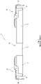
- the figure 1 shows an intermediate wall closure 1, as is known from the prior art.
- the intermediate wall closure 1 has a telescoping hollow profile 4, which has a clamping hook 3 on its opposite end faces 2, which engages over the respective end face 2 with a clamping jaw.
- a free space is created between the respective clamping jaw 10 and the respective end face 2, via which the intermediate wall closure 1 can be placed via an upper, horizontal longitudinal edge on a side wall 102 of a loading area 101 of a transport vehicle 100, as is shown in figure 2 is shown.
- the intermediate wall closure 1 can accordingly be fixed at a certain distance from the bottom of the loading area 101 in a substantially horizontal orientation transverse to the longitudinal direction of the loading area between the side walls 102 in order to secure the load 103 from slipping around and tipping over.
- the representation according to figure 2 1 illustrates that for a secure fixation of the intermediate wall closure 1 between the side walls 102 it is necessary for the clamping jaws 3 to provide sufficient clamping force to effectively avoid accidental displacement of the intermediate wall closure, for example when the transport vehicle brakes hard.
- the partition closure 1 has a telescoping intermediate section 13 between the opposite end faces.
- all profiles of the partition wall closure 1 can be designed as hollow profiles 4 pushed one on top of the other in a form-fitting manner.
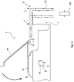
- the figure 3 shows an exemplary embodiment of a partition closure 1 according to the invention.
- this also has a clamping force indicator 5 accommodated in the hollow profile 4 of the partition closure 1 and displaceable in the longitudinal direction of the partition closure 1 against a mechanical clamping force.
- the clamping force indicator 5 projects out of the hollow profile 4 with a bearing surface 7 over the end face 2 .
- the partition closure 1 has an optical display 6, which adjusts itself proportionally to the mechanical clamping force.
- the distance by which the bearing surface 7 is further displaced in the direction of the hollow profile 7 can be used to determine the supporting force acting from the bearing surface 7 on the side wall and thus a corresponding clamping force with which the partition wall closure 1 is stuck on the side wall.
- the mechanical clamping force can, for example, by a spring element, for example by a Spiral spring or the like can be provided, which allows a particularly simple inference from the distance by which the bearing surface 7 has been displaced to the force acting on the bearing surface 7.
- the optical display 6 has a window which can be designed as an opening in the hollow profile 4 .
- An indicator element 12 can be seen through the window 11 , which element can be printed directly onto the clamping force indicator 5 .
- the clamping force indicator 5 can have a profile section or a piston accommodated essentially in a form-fitting manner in the hollow profile 4 , on whose end facing the end face 2 the bearing surface 7 is formed, with which it protrudes from the hollow profile 4 .
- the indicator element 12 can be an index which can be adjusted in relation to a reference mark on the outside of the hollow profile 4 .
- the clamping hook 3 can basically be designed as known from the prior art and has a pivoting lever 14 which is articulated via a toggle lever 15 to the clamping jaw 10 adjustable in the longitudinal direction of the hollow profile 4 and thus perpendicular to the end face 2 .
- the toggle lever 15 is articulated on the linearly adjustable clamping jaw 10 via a first articulation axis 12 and on the pivoting lever 14 via a second articulation axis 21 .
- the toggle lever 15 has an adjustable length and is coupled to the pivoting lever 14 via a threaded rod 16 .
- the threaded rod 16 in turn is supported on the pivoting lever 14 via a spring element 18, which in the present case is designed as a spiral spring. A screwed onto the threaded rod 16 nut 19, the bias of the spring element 18 and thus the zero position of the pivot lever 14 in the open position according to figure 3 to be set.
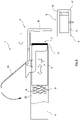
- the Figures 4 to 6 illustrate the example of an embodiment of the invention
- the locking process using a partition closure 1 according to the invention figure 4 shows the linear displacement of the clamping jaw 10 as a result of the actuation of the pivoting lever 14, the number I representing the open position of the clamping jaw 10 or the clamping lever 14 and the number II representing the closed position/locking position of the clamping jaw 10 or the pivoting lever 14.
- the clamping force indicator 5, which is present again in the embodiment according to the example figure 3 is formed is shown in the open position I of the pivoting lever 14 and the clamping jaw 10 .
- the symbolically drawn Partition 102 illustrates the clamping and supporting forces that act on the wall 102 in the locking position and cancel each other out, which act from the clamping jaw 10 from the outside on the wall 102 and from the bearing surface 7 on the inside of the wall 102 and thus the jamming of the Cause wall 102 between the jaw 10 and the bearing surface 7.
- the indicator element 12 is in the open position of the clamping hook with the pivoting lever 14 pivoted away from the hollow profile 4 and accordingly also with the wall element (not shown) unloaded when the clamping force indicator 5 is inserted is moved out of its target position marked by the arrow symbol for proper locking.
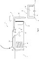
- the clamping force indicator 5 has a piston 17, which protrudes with a first of its opposite ends beyond the end face 2 of the hollow profile 4 and on its end face in turn has the bearing surface 7, while the piston 17 has its rear end facing away from the bearing surface 7 the elastic element 8 is supported on a support 22 in the hollow profile 4 .
- the figure 6 further illustrates that in the in figure 6 shown locked state with pivoted pivoted lever 14, the elastic element 8 in comparison to the representation according to figure 5 was further compressed as a result of the already described displacement of the piston 17 further into the interior of the hollow profile 4 .
- the indicator element 12 and the arrow symbol on the outside of the hollow profile 4 of the visual display 6 is aligned to indicate that a sufficient clamping force has been reached.
Landscapes
- Engineering & Computer Science (AREA)
- Transportation (AREA)
- Mechanical Engineering (AREA)
- Clamps And Clips (AREA)
Abstract
Description
- Die Erfindung geht aus von einem Zwischenwandverschluss zum Sichern von Ladegut auf einer Ladefläche eines Transportfahrzeugs, wobei der Zwischenwandverschluss an mindestens einer von zwei gegenüberliegenden Stirnseiten einen die Stirnseite mit einem einstellbaren Abstand überragenden und in Bezug auf die Stirnseite verspannbaren Klemmhaken aufweist. Ein derartiger Zwischenwandverschluss ist aus der
EP 1108 609 B1 bekannt. Ähnliche Zwischenwandverschlüsse beschreiben auch dieDE 20 2006 003 003 U1 und dieDE 10 2009 033 320 A1 . - Gattungsgemäße Zwischenwandverschlüsse dienen insbesondere dazu, um auf einer Ladefläche eines Transportfahrzeugs, beispielsweise in einem Kastenaufbau des Transportfahrzeugs aufgenommene Güter gegenüber dem Verrücken und dem Umfallen während des Transports zu sichern. Dabei werden Zwischenwandverschlüsse insbesondere dazu verwendet, um zwischen gegenüberliegenden Seitenwänden eines Kastenaufbaus fixiert, den Kastenaufbau in Längsrichtung in mehrere Unterabschnitte zu separieren, sodass Stützflächen für die auf der Ladefläche aufstehenden Güter bereitgestellt sind. Die Ladungssicherung mit Hilfe des Zwischenwandverschlusses erfolgt dabei derart, dass er manuell entsprechend den Abmessungen der verladenen Güter bedarfsweise beispielsweise an den bereits erwähnten Seitenwänden eines Kastenaufbaus fixiert wird, indem die bereits beschriebenen Klemmhaken die Seitenwände übergreifen und den Zwischenwandverschluss an den Seitenwänden verklemmen.
- Obschon auch bei den aus dem Stand der Technik bekannten Zwischenwandverschlüssen die Klemmhaken einstellbar sind, um auf unterschiedliche Seitenwanddicken zu reagieren, erfolgt diese Voreinstellung der Klemmhaken und damit die Bereitstellung der Klemmkraft, mit welcher der Zwischenwandverschluss an der Seitenwand verklemmt ist, ausschließlich aufgrund von Erfahrungswerten des Bedieners. Insbesondere geben die aus dem Stand der Technik bekannten Zwischenwandverschlüsse keinerlei Rückkopplung an den Bediener, inwiefern eine von dem Zwischenwandverschluss bereitgestellte Klemmkraft ausreichend sein könnte, um den Zwischenwandverschluss prozesssicher beispielsweise an den Seitenwänden zu verklemmen, sodass bei den im Fahrbetrieb auftretenden Belastungen durch gegen den Zwischenwandverschluss stoßendes Ladegut ein Verrücken des Zwischenwandverschlusses unterbleibt.
- Es ist daher die Aufgabe der Erfindung, einen Zwischenwandverschluss der eingangs beschriebenen Art derart weiterzuentwickeln, dass er für die reproduzierbare Bereitstellung einer sicherheitstechnisch relevanten Klemmkraft vorbereitet ist.
- Diese Aufgabe wird durch einen Zwischenwandverschluss mit den Merkmalen des Anspruchs 1 gelöst. Der nebengeordnete Anspruch 15 betrifft eine entsprechende Anordnung.
- Demgemäß ist bei dem Zwischenwandverschluss vorgesehen, dass dieser einen in einem Hohlprofil des Zwischenwandverschlusses aufgenommenen und in Längsrichtung des Zwischenwandverschlusses entgegen einer mechanischen Spannkraft verschieblichen Spannkraftindikator mit einer sich proportional zur mechanischen Spannkraft einstellenden optischen Anzeige aufweist.
- Die Idee der Erfindung liegt somit darin, an der Stirnseite des Zwischenwandverschlusses, mit welcher der Zwischenwandverschluss im Anwendungsfall laderauminnenseitig beispielsweise an einer Seitenwand eines Kastenaufbaus eines Transportfahrzeugs anliegt, einen Spannkraftindikator vorzusehen. Dies ist deshalb möglich, weil über die Stirnseite gerade die von dem die Stirnseite überragenden Klemmhaken bereitgestellte Klemmkraft bzw. entsprechend dem dritten Newtonschen Axiom eine entsprechende Gegenkraft anliegt, welche als Messgröße für die Quantifizierung der Klemmkraft, mit welcher der Zwischenwandverschluss an der Seitenwand befestigt ist, herangezogen werden kann.
- Der Spannkraftindikator kann mechanisch, elektrosensorisch oder als eine Kombination aus beidem ausgebildet sein. Bei einer elektrosensorischen Variante kann beispielsweise die Spannkraft an der Stirnseite des Zwischenwandverschlusses mit Hilfe eines piezoelektrischen Sensors erfasst werden. Bei einer vollmechanischen Variante kann ein elastisches Element mit einer definierten Kennlinie vorgesehen sein, etwa eine Feder, welches in Längsrichtung des Hohlprofils verlagert bzw. komprimiert wird und dementsprechend eine seiner Verlagerung bzw. Komprimierung proportionale, der Spannkraft entgegenwirkende Gegenkraft beispielsweise auf die Seitenwand eines Kastenaufbaus ausübt, welche erfindungsgemäß über die sich einstellende optische Anzeige anhand der Stellposition des elastischen Elements angezeigt werden kann.
- Der Spannkraftindikator kann mit einer Lagerfläche über die Stirnseite aus dem Hohlprofil herausragen, wobei sich die optische Anzeige proportional zu der senkrecht zu der Lagerfläche wirkenden Spannkraft einstellt. Die Lagerfläche kann Bestandteil eines Kolbens sein, mit dem der Spannkraftindikator über die Stirnseite aus dem Hohlprofil herausragt.
- Der Zwischenwandverschluss kann an beiden der gegenüberliegenden Stirnseiten jeweils einen die jeweilige Stirnseite mit einem einstellbaren Abstand überragenden und in Bezug auf die jeweilige Stirnseite verspannbaren Klemmhaken aufweisen. Dabei kann der Zwischenwandverschluss an beiden Stirnseiten jeweils einen in dem Hohlprofil des Zwischenwandverschlusses aufgenommenen und in Längsrichtung des Zwischenwandverschlusses verschieblichen Spannkraftindikator aufweisen, der mit einer jeweiligen Lagerfläche an der jeweiligen Stirnseite aus dem Hohlprofil herausragt.
- Der Spannkraftindikator kann einen Kolben aufweisen, der in Längsrichtung des Hohlprofils in dem Hohlprofil geführt ist und der mit einer Lagerfläche über die Stirnseite aus dem Hohlprofil herausragt.
- Der Spannkraftindikator kann ein elastisches Element aufweisen, das entgegen der mechanischen Spannkraft vorgespannt ist oder vorgespannt werden kann.
- Das elastische Element kann eine Feder, vorzugsweise eine Spiralfeder, mit einer Federkonstante aufweisen, die derart bemessen ist, dass der Spannkraftindikator in einer Verriegelungsposition des Klemmhakens, in welcher eine Klemmbacke des Klemmhakens der Stirnseite maximal angenähert und der Spannkraftindikator unter Vorspannung der Feder relativ zu einer Freigabeposition des Klemmhakens weiter in das Hohlprofil hinein verlagert ist, eine Mindestklemmkraft zwischen sich und der Klemmbacke ausübt.
- Der Spannkraftindikator, vorzugsweise ein Kolben des Spankraftindikators, kann in Richtung einer der Stirnseite unter einem Abstand gegenüberliegenden Klemmbacke des Klemmhakens vorgespannt sein oder vorgespannt werden.
- Das Hohlprofil kann an einer Längsseite ein Fenster oder einen Durchbruch aufweisen, der profilinnenseitig von dem Spannkraftindikator mit einem von dem Fenster oder dem Durchbruch freigelegten, vorzugsweise grafischen Indikatorelement überdeckt wird.
- Das Indikatorelement kann mindestens eine Linie aufweisen, die sich zumindest abschnittsweise parallel zu der Stirnseite erstreckt und abhängig von einer Stellposition des Spannkraftindikators in der Längsrichtung eine relative Anordnung in Bezug auf das Fenster oder den Durchbruch, oder deren jeweiliger Berandung, einnimmt. Das Indikatorelement kann eine Mehrzahl paralleler Linien aufweisen, die in Verstellrichtung des Spannkraftindikators zueinander beabstandet sind. Auf diese Weise können sie eine Skala bilden. Das Indikatorelement kann auch jeder andere Gestaltung aufweisen, welche dazu geeignet ist, eine geeignete Spannkraft zur Festlegung des Zwischenwandverschlusses in Abhängigkeit einer Stellposition des Indikatorelements in Bezug auf das Fenster oder den Durchbruch des Indikatorelements zumindest qualitativ anzuzeigen. Beispielsweise kann auch eine Farbskala auf dem Indikatorelement bereitgestellt sein.
- Der Zwischenwandverschluss kann einen zwischen den beiden gegenüberliegenden Stirnseiten angeordneten Zwischenabschnitt aufweisen, der in der Längsrichtung des Zwischenwandverschlusses teleskopierbar ist.
- Der Klemmhaken kann eine der Stirnseite unter einem Abstand gegenüberliegende Klemmbacke aufweisen, wobei der Abstand der Klemmbacke zu der Stirnseite über einen Schwenkhebel einstellbar ist, wozu der Schwenkhebel über einen Kniehebel an dem Klemmhaken angelenkt ist.
- Der Kniehebel kann eine einstellbare Länge aufweisen und dazu vorzugsweise über eine Gewindestange mit dem Schwenkhebel gekoppelt sein. Die Einstellung der Länge des Kniehebels kann mit Hilfe einer auf die Gewindestange aufgedreht Mutter erfolgen. Wenn der Kniehebel über eine Gewindestange mit dem Schwenkhebel gekoppelt ist, kann die Gewindestange über ein Federelement, vorzugsweise über eine Spiralfeder, an dem Schwenkhebel abgestützt sein.
- Alternativ zu dem Kniehebel mit der einstellbaren Länge kann auch vorgesehen sein, dass der Kniehebel eine feste Länge aufweist und den Schwenkhebel mit dem Klemmhaken starr verbindet. Diese Ausführungsform ist erfindungsgemäß bevorzugt, da sie gegenüber dem Kniehebel mit einstellbarer Länge konstruktiv einfacher ist. Aufgrund des entgegen einer mechanischen Spannkraft verschieblichen Spannkraftindikators ist es bei dem erfindungsgemäßen Zwischenwandverschluss nicht erforderlich, dass über eine Variation des Kniehebels die Anpassung des Klemmhakens an die vorgefundene Wanddicke erforderlich ist. Die Kompensation der Wanddicke kann anders bei den aus dem Stand der Technik bekannten Zwischenwandverschlüssen von dem entgegen der mechanischen Spannkraft verschieblichen Spannkraftindikator übernommen werden.
- Gemäß einem anderen Aspekt wird eine Anordnung zum Sichern von Ladung auf einer Ladefläche eines Transportfahrzeugs beschrieben, die mindestens einen Zwischenwandverschluss der zuvor beschriebenen Art aufweist. Die Anordnung weist weiterhin eine Ladefläche eines Transportfahrzeugs, beispielsweise eines Lastkraftwagens, mit einem Kastenaufbau auf. Die Ladefläche des Transportfahrzeugs kann zwei gegenüberliegende Seitenwände aufweisen, die über den Zwischenwandverschluss miteinander verbunden sind. Der Zwischenwandverschluss kann dabei mit seinem mindestens einen Klemmhaken eine der Seitenwände übergreifen und die Seitenwand zwischen sich und der Stirnseite mit der mechanischen Spannkraft einklemmen.
- Es müssen nicht zwingend beide der gegenüberliegenden Enden des Zwischenwandverschlusses erfindungsgemäß ausgebildet sein. Es ist auch denkbar, dass an einem der gegenüberliegenden Enden der Zwischenwandverschluss analog zu der technischen Lösung der
DE 10 2009 033 320 A1 ausgebildet ist. - Weitere Einzelheiten der Erfindung werden anhand der nachstehenden Figuren erläutert. Dabei zeigt:
- Figur 1
- in perspektivischer Darstellung einen Zwischenwandverschluss gemäß dem Stand der Technik;
- Figur 2
- eine Verladeanordnung unter Verwendung eines Zwischenwandverschlusses gemäß dem Stand der Technik;
- Figur 3
- eine Detailansicht einer erfindungsgemäßen Ausführungsform eines Zwischenwandverschlusses;
- Figur 4
- eine weitere Detailansicht eines erfindungsgemäßen Zwischenwandverschlusses mit einer Gegenüberstellung der Offenposition und der Verriegelungsposition des Klemmhakens;
- Figur 5
- eine weitere Ausführungsform eines erfindungsgemäßen Zwischenwandverschlusses in teiltransparenter Darstellung und in der Offenstellung des Klemmhakens; und
- Figur 6
- den Zwischenwandverschluss gemäß
Figur 5 in der Schließstellung des Klemmhakens. - Die
Figur 1 zeigt einen Zwischenwandverschluss 1, wie er aus dem Stand der Technik bekannt ist. Der Zwischenwandverschluss 1 weist ein teleskopierbares Hohlprofil 4 auf, das an seinen gegenüberliegenden Stirnseiten 2 jeweils einen Klemmhaken 3 aufweist, der die jeweilige Stirnseite 2 mit einer Klemmbacke übergreift. Zwischen der jeweiligen Klemmbacke 10 und der jeweiligen Stirnseite 2 ist ein Freiraum geschaffen, über den der Zwischenwandverschluss 1 über eine obere, horizontale Längskante auf eine Seitenwand 102 einer Ladefläche 101 eines Transportfahrzeugs 100 aufgesetzt werden kann, wie dies inFigur 2 gezeigt ist. Der Zwischenwandverschluss 1 kann demgemäß unter einem gewissen Abstand vom Boden der Ladefläche 101 in im Wesentlichen horizontaler Ausrichtung quer zur Längsrichtung der Ladefläche zwischen den Seitenwänden 102 fixiert werden, um die Ladung 103 vor Herumrutschen und Umkippen zu sichern. - Die Darstellung gemäß
Figur 2 veranschaulicht, dass es für eine sichere Fixierung des Zwischenwandverschlusses 1 zwischen den Seitenwänden 102 erforderlich ist, dass die Klemmbacken 3 eine ausreichende Klemmkraft bereitstellen, um das versehentliche Verrücken des Zwischenwandverschlusses beispielsweise bei einer Vollbremsung des Transportfahrzeugs wirksam zu vermeiden. Um eine Breitenanpassung des Zwischenwandverschlusses 1 zu erreichen, weist der Zwischenwandverschluss 1 in einen teleskopierbaren Zwischenabschnitt 13 zwischen den gegenüberliegenden Stirnseiten auf. Dazu können sämtliche Profile des Zwischenwandverschlusses 1 als formschlüssig aufeinander geschobene Hohlprofile 4 ausgebildet sein. - Die
Figur 3 zeigt eine beispielhafte Ausführungsform eines erfindungsgemäßen Zwischenwandverschlusses 1. Dieser weist neben dem Klemmhaken 3 weiterhin einen in dem Hohlprofil 4 des Zwischenwandverschlusses 1 aufgenommenen und in der Längsrichtung des Zwischenwandverschlusses 1 entgegen einer mechanischen Spannkraft verschieblichen Spannkraftindikator 5 auf. Der Spannkraftindikator 5 ragt mit einer Lagerfläche 7 über die Stirnseite 2 aus dem Hohlprofil 4 heraus. Für die Rückkopplung der eingestellten Spannkraft an den Benutzer weist der Zwischenwandverschluss 1 eine optische Anzeige 6 auf, welche sich proportional zu der mechanischen Spannkraft einstellt. Wenn somit in den zwischen der Klemmbacke 10 und der Lagerfläche 7 des Spannkraftindikators 5 bereitgestellten Freiraum an der Stirnseite 2 des Zwischenwandverschlusses 1 eine Seitenwand eingesetzt bzw. der Zwischenwandverschluss 1 in der zuvor mit Bezug auf dieFiguren 1 und2 beschriebenen Weise auf die Seitenwand aufgesetzt wird, kann durch Betätigen des Schwenkhebels 14 die Klemmbacke 10 weiter in Richtung der Lagerfläche 7 an der Stirnseite 2 angenähert werden. Wenn die Lagerfläche 7 an der dem Laderaum zugewandten Innenseite der Seitenwand zur Anlage kommt, führt weiteres Verschwenken des Schwenkhebels 14 dazu, dass der Spannkraftindikator 5 entgegen seiner mechanischen Spannkraft in das Hohlprofil 4 des Zwischenwandverschlusses 1 hineingeschoben wird. - Bei Kenntnis einer Kennlinie des Spannkraftindikators 5 kann aus der Wegstrecke, um welche die Lagerfläche 7 weiter in Richtung des Hohlprofils 7 verlagert wird, auf die von der Lagerfläche 7 auf die Seitenwand einwirkende Abstützkraft und damit auf eine entsprechende Klemmkraft geschlossen werden, mit welcher der Zwischenwandverschluss 1 an der Seitenwand verklemmt ist. Die mechanische Spannkraft kann dazu beispielsweise von einem Federelement, beispielsweise von einer Spiralfeder oder dergleichen bereitgestellt werden, welche einen besonders einfachen Rückschluss aus der Wegstrecke, um welche die Lagerfläche 7 verlagert worden ist, auf die auf die Lagerfläche 7 wirkende Kraft zulässt.
- Die optische Anzeige 6 weist ein Fenster auf, welches als ein Durchbruch in dem Hohlprofil 4 ausgebildet sein kann. Durch das Fenster 11 hindurch ist ein Indikatorelement 12 erkennbar, welches unmittelbar auf den Spannkraftindikator 5 aufgedruckt sein kann. Dazu kann der Spannkraftindikator 5 einen im Wesentlichen formschlüssig in dem Hohlprofil 4 aufgenommenen Profilabschnitt bzw. einen Kolben aufweisen, an dessen der Stirnseite 2 zugewandtem Ende die Lagerfläche 7 ausgebildet ist, mit welcher er aus dem Hohlprofil 4 herausragt. Wie in der
Figur 3 dargestellt ist, kann das Indikatorelement 12 ein Index sein, welcher in Bezug auf eine Referenzmarkierung an der Außenseite des Hohlprofils 4 verstellbar ist. - Der Klemmhaken 3 kann grundsätzlich wie aus dem Stand der Technik bekannt ausgebildet sein und weist dazu einen Schwenkhebel 14 auf, der über einen Kniehebel 15 an die in Längsrichtung des Hohlprofils 4 und damit senkrecht zu der Stirnseite 2 verstellbare Klemmbacke 10 angelenkt ist. Der Kniehebel 15 ist über eine erste Gelenkachse 12 an der linear verstellbaren Klemmbacke 10 und über eine zweite Gelenkachse 21 an den Schwenkhebel 14 angelenkt. Der Kniehebel 15 weist eine einstellbare Länge auf und ist dazu über eine Gewindestange 16 mit dem Schwenkhebel 14 gekoppelt. Die Gewindestange 16 wiederum ist über ein Federelement 18, welches vorliegend als eine Spiralfeder ausgebildet ist, an dem Schwenkhebel 14 abgestützt. Über eine auf die Gewindestange 16 aufgeschraubte Mutter 19 kann die Vorspannung des Federelements 18 und damit die Nulllage des Schwenkhebels 14 in der Offenposition gemäß
Figur 3 eingestellt werden. - Die
Figuren 4 bis 6 veranschaulichen am Beispiel einer Ausführungsform der Erfindung den Verriegelungsvorgang mit Hilfe eines erfindungsgemäßen Zwischenwandverschlusses 1. DieFigur 4 zeigt die lineare Verstellung der Klemmbacke 10 infolge der Betätigung des Schwenkhebels 14, wobei mit der Ziffer I die Offenstellung der Klemmbacke 10 bzw. des Klemmhebels 14 und mit II die Schließstellung/Verriegelungsposition der Klemmbacke 10 bzw. des Schwenkhebels 14 dargestellt ist. Der Spannkraftindikator 5, der vorliegend wieder in der Ausführung gemäß dem Beispiel nachFigur 3 ausgebildet ist, ist in der Offenposition I des Schwenkhebels 14 bzw. der Klemmbacke 10 gezeigt. Die symbolisch eingezeichnete Trennwand 102 veranschaulicht die in der Verriegelungsposition auf die Wand 102 wirkenden und sich gegenseitig aufhebenden Klemm- und Stützkräfte, die von der Klemmbacke 10 von der Außenseite auf die Wand 102 und von der Lagerfläche 7 an der Innenseite der Wand 102 wirken und damit die Verklemmung der Wand 102 zwischen der Klemmbacke 10 und der Lagerfläche 7 bewirken. - Wie in
Figur 5 gezeigt ist, ist das Indikatorelement 12 in der Offenstellung des Klemmhakens mit von dem Hohlprofil 4 abgeschwenktem Schwenkhebel 14 und dementsprechend auch bei eingesetztem Wandelement (nicht dargestellt) unbelastetem Spannkraftindikator 5 aus seiner durch das Pfeilsymbol gekennzeichneten Sollposition für eine ordnungsgemäße Verriegelung herausbewegt. - Wenn in den Zwischenraum zwischen der Lagerfläche 7 und der Klemmbacke 10 ein Wandelement eingelegt ist und der Schwenkhebel 14 in die in
Figur 6 gezeigte eingeklappte Position verschwenkt wird, bewegt sich die Klemmbacke 10 weiter in Richtung der Lagerfläche 7, bis erstmalig sowohl die Klemmbacke 10 als auch die Lagerfläche 7 an gegenüberliegenden Seiten der Seitenwand zur Anlage kommen. Weiteres Verschwenken des Klemmhebels 14 in Richtung Schließstellung führt dazu, dass entsprechend des Weiteren sich Annäherns der Klemmbacke 10 an die Stirnseite 2 des Zwischenwandverschlusses 1 die Lagerfläche 7, mit welcher der Spannkraftindikator 5 über die Stirnseite 2 aus dem Hohlprofil 4 herausragt, weiter in Richtung des Hohlprofils 4 verlagert wird. Diese Verlagerung erfolgt entgegen einer mechanischen Spannkraft, welche von dem elastischen Element 8 in dem Hohlprofil 4 auf den Spannkraftindikator 5 ausgeübt wird. Dazu weist der Spannkraftindikator 5 einen Kolben 17 auf, der mit einem ersten seiner gegenüberliegenden Enden über die Stirnseite 2 aus dem Hohlprofil 4 herausragt und an seiner Stirnseite wiederum die Lagerfläche 7 aufweist, während der Kolben 17 über sein der Lagerfläche 7 abgewandtes, rückwärtiges Ende über das elastische Element 8 an einer Abstützung 22 in dem Hohlprofil 4 abgestützt ist. - Die
Figur 6 veranschaulicht weiterhin, dass in dem inFigur 6 dargestellten Verriegelungszustand mit angeschwenktem Schwenkhebel 14 das elastische Element 8 im Vergleich zu der Darstellung gemäßFigur 5 weiter komprimiert wurde infolge der bereits beschriebenen Verlagerung des Kolbens 17 weiter in das Innere des Hohlprofils 4 hinein. Infolge dieser Verlagerung wiederum wurden das Indikatorelement 12 und das Pfeilsymbol an der Außenseite des Hohlprofils 4 der optischen Anzeige 6 in die Flucht gebracht, um das Erreichen einer hinreichenden Klemmkraft anzuzeigen. - Die in der vorstehenden Beschreibung, in der Zeichnung sowie in den Ansprüchen offenbarten Merkmale der Erfindung können sowohl einzeln als auch in beliebiger Kombination für die Verwirklichung der Erfindung wesentlich sein.
-
- 1
- Zwischenwandverschluss
- 2
- Stirnseite
- 3
- Klemmhaken
- 4
- Hohlprofil
- 5
- Spannkraftindikator
- 6
- optische Anzeige
- 7
- Lagerfläche
- 8
- elastisches Element
- 9
- Feder
- 10
- Klemmbacke
- 11
- Fenster
- 12
- Indikatorelement
- 13
- Zwischenabschnitt
- 14
- Schwenkhebel
- 15
- Kniehebel
- 16
- Gewindestange
- 18
- Federelement
- 19
- Mutter
- 20
- erste Gelenkachse
- 21
- zweite Gelenkachse
- 22
- Abstützung
- 100
- Transportfahrzeug
- 101
- Ladefläche
- 102
- Seitenwand
- 103
- Ladung
Claims (15)
- Zwischenwandverschluss (1) zum Sichern von Ladung (103) auf einer Ladefläche (101) eines Transportfahrzeugs (100), wobei der Zwischenwandverschluss (1) an mindestens einer von zwei gegenüberliegenden Stirnseiten (2) einen die Stirnseite (2) mit einem einstellbaren Abstand überragenden und in Bezug auf die Stirnseite (2) verspannbaren Klemmhaken (3) aufweist, dadurch gekennzeichnet, dass der Zwischenwandverschluss (1) einen in einem Hohlprofil (4) des Zwischenwandverschlusses (1) aufgenommenen und in Längsrichtung des Zwischenwandverschlusses (1) entgegen einer mechanischen Spannkraft verschieblichen Spannkraftindikator (5) mit einer sich proportional zur mechanischen Spannkraft einstellenden optischen Anzeige (6) aufweist.
- Zwischenwandverschluss (1) nach Anspruch 1, bei dem der Spannkraftindikator (5) mit einer Lagerfläche (7) über die Stirnseite (2) aus dem Hohlprofil (4) herausragt, wobei sich die optische Anzeige (6) proportional zu der senkrecht zu der Lagerfläche (7) wirkenden Spannkraft einstellt.
- Zwischenwandverschluss (1) nach Anspruch 1 oder 2, der an beiden der gegenüberliegenden Stirnseiten (2) jeweils einen die jeweilige Stirnseite (2) mit einem einstellbaren Abstand überragenden und in Bezug auf die jeweilige Stirnseite (2) verspannbaren Klemmhaken (3) aufweist, wobei der Zwischenwandverschluss (1) an beiden Stirnseiten (2) jeweils einen in dem Hohlprofil (4) des Zwischenwandverschlusses (1) aufgenommenen und in Längsrichtung des Zwischenwandverschlusses (1) verschieblichen Spannkraftindikator (5) aufweist, der mit einer jeweilige Lagerfläche (7) an der jeweiligen Stirnseite (2) aus dem Hohlprofil (4) herausragt.
- Zwischenwandverschluss (1) nach einem der vorangegangenen Ansprüche, bei dem der Spannkraftindikator (5) einen Kolben (17) aufweist, der in Längsrichtung des Hohlprofils (4) in dem Hohlprofil (4) geführt ist und der mit einer Lagerfläche (7) über die Stirnseite (2) aus dem Hohlprofil (4) herausragt.
- Zwischenwandverschluss (1) nach einem der vorangegangenen Ansprüche, bei dem der Spannkraftindikator (5) ein elastisches Element (8) aufweist, das entgegen der mechanischen Spannkraft vorgespannt ist oder vorgespannt werden kann.
- Zwischenwandverschluss (1) nach Anspruch 5, bei dem das elastische Element (8) eine Feder (9), vorzugsweise eine Spiralfeder, mit einer Federkonstante aufweist, die derart bemessen ist, dass der Spannkraftindikator (5) in einer Verriegelungsposition des Klemmhakens (3), in welcher eine Klemmbacke (10) des Klemmhaken (3) der Stirnseite (2) maximal angenähert und der Spannkraftindikator (5) zur Aufrechterhaltung eines einer Wandstärke entsprechenden Abstandes zwischen der Lagerfläche (7) und der Klemmbacke (10) unter Vorspannung der Feder (9) relativ zu einer Freigabeposition des Klemmhakens (3) weiter in das Hohlprofil (4) hinein verlagert ist, eine bestimmte Mindestklemmkraft zwischen sich und der Klemmbacke (10) ausübt.
- Zwischenwandverschluss (1) nach einem der vorangegangenen Ansprüche, bei dem der Spannkraftindikator (5), vorzugsweise ein Kolben (17) des Spankraftindikators, in Richtung einer der Stirnseite (2) unter einem Abstand gegenüberliegenden Klemmbacke (10) des Klemmhakens (3) vorgespannt ist oder vorgespannt werden kann.
- Zwischenwandverschluss (1) nach einem der vorangegangenen Ansprüche, bei dem das Hohlprofil (4) an einer Längsseite ein Fenster (11) oder einen Durchbruch aufweist, der profilinnenseitig von dem Spannkraftindikator (5) mit einem von dem Fenster (11) oder dem Durchbruch freigelegten, vorzugsweise grafischen Indikatorelement (12) überdeckt wird.
- Zwischenwandverschluss (1) nach Anspruch 8, bei dem das Indikatorelement (12) mindestens eine Linie aufweist, die sich zumindest abschnittsweise parallel zu der Stirnseite (2) erstreckt und abhängig von einer Stellposition des Spannkraftindikators (5) in der Längsrichtung eine relative Anordnung in Bezug auf das Fenster (11) oder den Durchbruch einnimmt.
- Zwischenwandverschluss (1) nach einem der vorangegangenen Ansprüche, der einen zwischen den beiden gegenüberliegenden Stirnseiten (2) angeordneten Zwischenabschnitt (13) aufweist, der in der Längsrichtung des Zwischenwandverschlusses (1) teleskopierbar ist.
- Zwischenwandverschluss (1) nach einem der vorangegangenen Ansprüche, bei dem der Klemmhaken (3) eine der Stirnseite (2) unter einem Abstand gegenüberliegende Klemmbacke (10) aufweist, wobei der Abstand der Klemmbacke (10) zu der Stirnseite (2) über einen Schwenkhebel (14) einstellbar ist, wozu der Schwenkhebel (14) über einen Kniehebel (15) an dem Klemmhaken (3) angelenkt ist.
- Zwischenwandverschluss (1) nach Anspruch 11, bei dem der Kniehebel (15) eine einstellbare Länge aufweist und dazu vorzugsweise über eine Gewindestange (16) mit dem Schwenkhebel (14) gekoppelt ist.
- Zwischenwandverschluss (1) nach Anspruch 11 oder 12, bei dem der Kniehebel (15) über eine Gewindestange (16) mit dem Schwenkhebel (14) gekoppelt ist, wobei die Gewindestange (16) über ein Federelement (18), vorzugsweise über eine Spiralfeder, an dem Schwenkhebel (14) abgestützt ist.
- Zwischenwandverschluss (1) nach einem der Ansprüche 1 bis 11, bei dem Kniehebel (15) eine feste Länge aufweist und den Schwenkhebel (14) mit dem Klemmhaken (3) starr verbindet.
- Anordnung zum Sichern von Ladung (103) auf einer Ladefläche (101) eines Transportfahrzeugs (100), wobei die Anordnung mindestens einen Zwischenwandverschluss (1) nach einem der vorangegangen Ansprüche sowie eine Ladefläche (101) eines Transportfahrzeugs (100) aufweist, die zwei gegenüberliegende Seitenwände (102) aufweist, die über den Zwischenwandverschluss (1) miteinander verbunden sind, wobei der Zwischenwandverschluss (1) mit seinem mindestens einen Klemmhaken (3) eine der Seitenwände (102) übergreift und die Seitenwand (102) zwischen sich und der Stirnseite (2) mit der mechanischen Spannkraft einklemmt.
Priority Applications (3)
| Application Number | Priority Date | Filing Date | Title |
|---|---|---|---|
| HUE21187148A HUE070371T2 (hu) | 2021-07-22 | 2021-07-22 | Válaszfalrögzítõ szerkezet rakomány biztosítására egy szállítójármû rakfelületén, valamint egy megfelelõ elrendezés |
| PL21187148.8T PL4122763T3 (pl) | 2021-07-22 | 2021-07-22 | Zamknięcie przegrody pośredniej do zabezpieczania ładunku na powierzchni ładunkowej pojazdu transportowego i odpowiadający jej układ |
| EP21187148.8A EP4122763B1 (de) | 2021-07-22 | 2021-07-22 | Zwischenwandverschluss zum sichern von ladung auf einer ladefläche eines transportfahrzeugs sowie eine entsprechende anordnung |
Applications Claiming Priority (1)
| Application Number | Priority Date | Filing Date | Title |
|---|---|---|---|
| EP21187148.8A EP4122763B1 (de) | 2021-07-22 | 2021-07-22 | Zwischenwandverschluss zum sichern von ladung auf einer ladefläche eines transportfahrzeugs sowie eine entsprechende anordnung |
Publications (2)
| Publication Number | Publication Date |
|---|---|
| EP4122763A1 true EP4122763A1 (de) | 2023-01-25 |
| EP4122763B1 EP4122763B1 (de) | 2024-12-25 |
Family
ID=77021242
Family Applications (1)
| Application Number | Title | Priority Date | Filing Date |
|---|---|---|---|
| EP21187148.8A Active EP4122763B1 (de) | 2021-07-22 | 2021-07-22 | Zwischenwandverschluss zum sichern von ladung auf einer ladefläche eines transportfahrzeugs sowie eine entsprechende anordnung |
Country Status (3)
| Country | Link |
|---|---|
| EP (1) | EP4122763B1 (de) |
| HU (1) | HUE070371T2 (de) |
| PL (1) | PL4122763T3 (de) |
Cited By (1)
| Publication number | Priority date | Publication date | Assignee | Title |
|---|---|---|---|---|
| DE102024125979A1 (de) | 2024-09-10 | 2026-03-12 | Pwp S.A. | Sperrbalken zur Ladungssicherung |
Citations (5)
| Publication number | Priority date | Publication date | Assignee | Title |
|---|---|---|---|---|
| US20060051178A1 (en) * | 2004-09-07 | 2006-03-09 | Burns Bros., Inc. | Cargo stabilizing structures |
| DE202006003003U1 (de) | 2006-02-24 | 2006-08-10 | Fuchs, Walter | Zwischenwandverschlussendstück für erhöhte Rückhaltefähigkeit |
| DE202008012788U1 (de) * | 2008-09-25 | 2008-11-27 | Allsafe Jungfalk Gmbh & Co. Kg | Sperrbalken |
| DE102009033320A1 (de) | 2009-07-15 | 2011-02-24 | Manfred Berger | Zwischenwandverschluß |
| CN211765202U (zh) * | 2019-11-25 | 2020-10-27 | 浙江双友物流器械股份有限公司 | 一种货夹 |
Family Cites Families (1)
| Publication number | Priority date | Publication date | Assignee | Title |
|---|---|---|---|---|
| EP3842183B1 (de) * | 2019-12-23 | 2024-10-30 | WISTRA GmbH Cargo Control | Klemmvorrichtung |
-
2021
- 2021-07-22 HU HUE21187148A patent/HUE070371T2/hu unknown
- 2021-07-22 EP EP21187148.8A patent/EP4122763B1/de active Active
- 2021-07-22 PL PL21187148.8T patent/PL4122763T3/pl unknown
Patent Citations (5)
| Publication number | Priority date | Publication date | Assignee | Title |
|---|---|---|---|---|
| US20060051178A1 (en) * | 2004-09-07 | 2006-03-09 | Burns Bros., Inc. | Cargo stabilizing structures |
| DE202006003003U1 (de) | 2006-02-24 | 2006-08-10 | Fuchs, Walter | Zwischenwandverschlussendstück für erhöhte Rückhaltefähigkeit |
| DE202008012788U1 (de) * | 2008-09-25 | 2008-11-27 | Allsafe Jungfalk Gmbh & Co. Kg | Sperrbalken |
| DE102009033320A1 (de) | 2009-07-15 | 2011-02-24 | Manfred Berger | Zwischenwandverschluß |
| CN211765202U (zh) * | 2019-11-25 | 2020-10-27 | 浙江双友物流器械股份有限公司 | 一种货夹 |
Cited By (2)
| Publication number | Priority date | Publication date | Assignee | Title |
|---|---|---|---|---|
| DE102024125979A1 (de) | 2024-09-10 | 2026-03-12 | Pwp S.A. | Sperrbalken zur Ladungssicherung |
| EP4711202A1 (de) | 2024-09-10 | 2026-03-18 | Pwp Sa | Sperrbalken zur ladungssicherung |
Also Published As
| Publication number | Publication date |
|---|---|
| PL4122763T3 (pl) | 2025-04-22 |
| HUE070371T2 (hu) | 2025-06-28 |
| EP4122763B1 (de) | 2024-12-25 |
Similar Documents
| Publication | Publication Date | Title |
|---|---|---|
| EP1544379B1 (de) | Klemmvorrichtung | |
| EP4122763B1 (de) | Zwischenwandverschluss zum sichern von ladung auf einer ladefläche eines transportfahrzeugs sowie eine entsprechende anordnung | |
| EP0941889A2 (de) | Ausziehvorrichtung | |
| DE602004010217T2 (de) | Verriegelungsvorrichtung mit einem Gelenkhebel zum Spannen von Werkstücken | |
| DE102020203827A1 (de) | Lenksäule für ein Kraftfahrzeug | |
| EP3842183B1 (de) | Klemmvorrichtung | |
| DE102009040121B4 (de) | Sperrbalken | |
| DE1940861C3 (de) | Abschließbarer Schiträger für Kraftfahrzeuge | |
| DE102014218227A1 (de) | Dachträgeranordnung für ein Kraftfahrzeug | |
| EP0826850A2 (de) | Fassadenunterkonstruktion | |
| EP4060153B1 (de) | Türfeststeller | |
| EP1431115B1 (de) | Verstellbare Ladungsstange für einen LKW | |
| EP4190640A1 (de) | Dachträgeranordnung für ein kraftfahrzeug | |
| DE102014207832B4 (de) | Dachträgeranordnung für ein Kraftfahrzeug | |
| EP3287663B1 (de) | Schubkettenzahnstange | |
| EP1033284A2 (de) | Strebenartige Transportsicherungsvorrichtung | |
| DE2530611C2 (de) | Wandbefestigungselement für Plattenheizkörper | |
| DE2815845A1 (de) | Vorrichtung zum leichteren loesen festsitzender radschrauben und -muttern | |
| DE102017100113B4 (de) | Planenaufrollsystem | |
| DE102020109274B3 (de) | Zurröse mit Mittelstück zur Anordnung an einer Ladefläche eines Transportfahrzeuges | |
| DE2020123C3 (de) | Verladebrücke | |
| DE202009001993U1 (de) | Seitenplanenspanner | |
| DE102024124564A1 (de) | Spannvorrichtung für einen Zwischenwandverschluss und Zwischenwandverschluss mit wenigstens einer Spannvorrichtung zum selbstverstärkenden Klemmen | |
| DE9307367U1 (de) | Halterungsvorrichtung mit Schwenkeinrichtung | |
| DE10025180A1 (de) | Halterung zur Fixierung eines Gegenstandes, insbesondere einer Leuchte |
Legal Events
| Date | Code | Title | Description |
|---|---|---|---|
| PUAI | Public reference made under article 153(3) epc to a published international application that has entered the european phase |
Free format text: ORIGINAL CODE: 0009012 |
|
| STAA | Information on the status of an ep patent application or granted ep patent |
Free format text: STATUS: REQUEST FOR EXAMINATION WAS MADE |
|
| 17P | Request for examination filed |
Effective date: 20220719 |
|
| AK | Designated contracting states |
Kind code of ref document: A1 Designated state(s): AL AT BE BG CH CY CZ DE DK EE ES FI FR GB GR HR HU IE IS IT LI LT LU LV MC MK MT NL NO PL PT RO RS SE SI SK SM TR |
|
| STAA | Information on the status of an ep patent application or granted ep patent |
Free format text: STATUS: EXAMINATION IS IN PROGRESS |
|
| 17Q | First examination report despatched |
Effective date: 20231002 |
|
| GRAP | Despatch of communication of intention to grant a patent |
Free format text: ORIGINAL CODE: EPIDOSNIGR1 |
|
| STAA | Information on the status of an ep patent application or granted ep patent |
Free format text: STATUS: GRANT OF PATENT IS INTENDED |
|
| INTG | Intention to grant announced |
Effective date: 20240610 |
|
| GRAJ | Information related to disapproval of communication of intention to grant by the applicant or resumption of examination proceedings by the epo deleted |
Free format text: ORIGINAL CODE: EPIDOSDIGR1 |
|
| STAA | Information on the status of an ep patent application or granted ep patent |
Free format text: STATUS: EXAMINATION IS IN PROGRESS |
|
| INTC | Intention to grant announced (deleted) | ||
| GRAS | Grant fee paid |
Free format text: ORIGINAL CODE: EPIDOSNIGR3 |
|
| STAA | Information on the status of an ep patent application or granted ep patent |
Free format text: STATUS: GRANT OF PATENT IS INTENDED |
|
| GRAP | Despatch of communication of intention to grant a patent |
Free format text: ORIGINAL CODE: EPIDOSNIGR1 |
|
| GRAA | (expected) grant |
Free format text: ORIGINAL CODE: 0009210 |
|
| STAA | Information on the status of an ep patent application or granted ep patent |
Free format text: STATUS: THE PATENT HAS BEEN GRANTED |
|
| INTG | Intention to grant announced |
Effective date: 20241114 |
|
| AK | Designated contracting states |
Kind code of ref document: B1 Designated state(s): AL AT BE BG CH CY CZ DE DK EE ES FI FR GB GR HR HU IE IS IT LI LT LU LV MC MK MT NL NO PL PT RO RS SE SI SK SM TR |
|
| REG | Reference to a national code |
Ref country code: GB Ref legal event code: FG4D Free format text: NOT ENGLISH |
|
| REG | Reference to a national code |
Ref country code: CH Ref legal event code: EP |
|
| REG | Reference to a national code |
Ref country code: DE Ref legal event code: R096 Ref document number: 502021006189 Country of ref document: DE |
|
| REG | Reference to a national code |
Ref country code: IE Ref legal event code: FG4D Free format text: LANGUAGE OF EP DOCUMENT: GERMAN |
|
| REG | Reference to a national code |
Ref country code: LT Ref legal event code: MG9D |
|
| PG25 | Lapsed in a contracting state [announced via postgrant information from national office to epo] |
Ref country code: HR Free format text: LAPSE BECAUSE OF FAILURE TO SUBMIT A TRANSLATION OF THE DESCRIPTION OR TO PAY THE FEE WITHIN THE PRESCRIBED TIME-LIMIT Effective date: 20241225 |
|
| PG25 | Lapsed in a contracting state [announced via postgrant information from national office to epo] |
Ref country code: FI Free format text: LAPSE BECAUSE OF FAILURE TO SUBMIT A TRANSLATION OF THE DESCRIPTION OR TO PAY THE FEE WITHIN THE PRESCRIBED TIME-LIMIT Effective date: 20241225 |
|
| PG25 | Lapsed in a contracting state [announced via postgrant information from national office to epo] |
Ref country code: BG Free format text: LAPSE BECAUSE OF FAILURE TO SUBMIT A TRANSLATION OF THE DESCRIPTION OR TO PAY THE FEE WITHIN THE PRESCRIBED TIME-LIMIT Effective date: 20241225 |
|
| PG25 | Lapsed in a contracting state [announced via postgrant information from national office to epo] |
Ref country code: NO Free format text: LAPSE BECAUSE OF FAILURE TO SUBMIT A TRANSLATION OF THE DESCRIPTION OR TO PAY THE FEE WITHIN THE PRESCRIBED TIME-LIMIT Effective date: 20250325 |
|
| PG25 | Lapsed in a contracting state [announced via postgrant information from national office to epo] |
Ref country code: GR Free format text: LAPSE BECAUSE OF FAILURE TO SUBMIT A TRANSLATION OF THE DESCRIPTION OR TO PAY THE FEE WITHIN THE PRESCRIBED TIME-LIMIT Effective date: 20250326 Ref country code: LV Free format text: LAPSE BECAUSE OF FAILURE TO SUBMIT A TRANSLATION OF THE DESCRIPTION OR TO PAY THE FEE WITHIN THE PRESCRIBED TIME-LIMIT Effective date: 20241225 |
|
| PG25 | Lapsed in a contracting state [announced via postgrant information from national office to epo] |
Ref country code: RS Free format text: LAPSE BECAUSE OF FAILURE TO SUBMIT A TRANSLATION OF THE DESCRIPTION OR TO PAY THE FEE WITHIN THE PRESCRIBED TIME-LIMIT Effective date: 20250325 |
|
| REG | Reference to a national code |
Ref country code: NL Ref legal event code: MP Effective date: 20241225 |
|
| PG25 | Lapsed in a contracting state [announced via postgrant information from national office to epo] |
Ref country code: NL Free format text: LAPSE BECAUSE OF FAILURE TO SUBMIT A TRANSLATION OF THE DESCRIPTION OR TO PAY THE FEE WITHIN THE PRESCRIBED TIME-LIMIT Effective date: 20241225 |
|
| REG | Reference to a national code |
Ref country code: HU Ref legal event code: AG4A Ref document number: E070371 Country of ref document: HU |
|
| PG25 | Lapsed in a contracting state [announced via postgrant information from national office to epo] |
Ref country code: SM Free format text: LAPSE BECAUSE OF FAILURE TO SUBMIT A TRANSLATION OF THE DESCRIPTION OR TO PAY THE FEE WITHIN THE PRESCRIBED TIME-LIMIT Effective date: 20241225 |
|
| PG25 | Lapsed in a contracting state [announced via postgrant information from national office to epo] |
Ref country code: ES Free format text: LAPSE BECAUSE OF FAILURE TO SUBMIT A TRANSLATION OF THE DESCRIPTION OR TO PAY THE FEE WITHIN THE PRESCRIBED TIME-LIMIT Effective date: 20241225 |
|
| PG25 | Lapsed in a contracting state [announced via postgrant information from national office to epo] |
Ref country code: IS Free format text: LAPSE BECAUSE OF FAILURE TO SUBMIT A TRANSLATION OF THE DESCRIPTION OR TO PAY THE FEE WITHIN THE PRESCRIBED TIME-LIMIT Effective date: 20250425 |
|
| PG25 | Lapsed in a contracting state [announced via postgrant information from national office to epo] |
Ref country code: PT Free format text: LAPSE BECAUSE OF FAILURE TO SUBMIT A TRANSLATION OF THE DESCRIPTION OR TO PAY THE FEE WITHIN THE PRESCRIBED TIME-LIMIT Effective date: 20250428 |
|
| PG25 | Lapsed in a contracting state [announced via postgrant information from national office to epo] |
Ref country code: EE Free format text: LAPSE BECAUSE OF FAILURE TO SUBMIT A TRANSLATION OF THE DESCRIPTION OR TO PAY THE FEE WITHIN THE PRESCRIBED TIME-LIMIT Effective date: 20241225 |
|
| PG25 | Lapsed in a contracting state [announced via postgrant information from national office to epo] |
Ref country code: RO Free format text: LAPSE BECAUSE OF FAILURE TO SUBMIT A TRANSLATION OF THE DESCRIPTION OR TO PAY THE FEE WITHIN THE PRESCRIBED TIME-LIMIT Effective date: 20241225 |
|
| PG25 | Lapsed in a contracting state [announced via postgrant information from national office to epo] |
Ref country code: SK Free format text: LAPSE BECAUSE OF FAILURE TO SUBMIT A TRANSLATION OF THE DESCRIPTION OR TO PAY THE FEE WITHIN THE PRESCRIBED TIME-LIMIT Effective date: 20241225 |
|
| PG25 | Lapsed in a contracting state [announced via postgrant information from national office to epo] |
Ref country code: CZ Free format text: LAPSE BECAUSE OF FAILURE TO SUBMIT A TRANSLATION OF THE DESCRIPTION OR TO PAY THE FEE WITHIN THE PRESCRIBED TIME-LIMIT Effective date: 20241225 |
|
| PG25 | Lapsed in a contracting state [announced via postgrant information from national office to epo] |
Ref country code: IT Free format text: LAPSE BECAUSE OF FAILURE TO SUBMIT A TRANSLATION OF THE DESCRIPTION OR TO PAY THE FEE WITHIN THE PRESCRIBED TIME-LIMIT Effective date: 20241225 |
|
| PGFP | Annual fee paid to national office [announced via postgrant information from national office to epo] |
Ref country code: HU Payment date: 20250709 Year of fee payment: 5 |
|
| PG25 | Lapsed in a contracting state [announced via postgrant information from national office to epo] |
Ref country code: SE Free format text: LAPSE BECAUSE OF FAILURE TO SUBMIT A TRANSLATION OF THE DESCRIPTION OR TO PAY THE FEE WITHIN THE PRESCRIBED TIME-LIMIT Effective date: 20241225 |
|
| REG | Reference to a national code |
Ref country code: DE Ref legal event code: R097 Ref document number: 502021006189 Country of ref document: DE |
|
| PG25 | Lapsed in a contracting state [announced via postgrant information from national office to epo] |
Ref country code: DK Free format text: LAPSE BECAUSE OF FAILURE TO SUBMIT A TRANSLATION OF THE DESCRIPTION OR TO PAY THE FEE WITHIN THE PRESCRIBED TIME-LIMIT Effective date: 20241225 |
|
| PGFP | Annual fee paid to national office [announced via postgrant information from national office to epo] |
Ref country code: DE Payment date: 20250728 Year of fee payment: 5 |
|
| PGFP | Annual fee paid to national office [announced via postgrant information from national office to epo] |
Ref country code: PL Payment date: 20250711 Year of fee payment: 5 |
|
| PGFP | Annual fee paid to national office [announced via postgrant information from national office to epo] |
Ref country code: AT Payment date: 20251020 Year of fee payment: 5 |
|
| PLBE | No opposition filed within time limit |
Free format text: ORIGINAL CODE: 0009261 |
|
| STAA | Information on the status of an ep patent application or granted ep patent |
Free format text: STATUS: NO OPPOSITION FILED WITHIN TIME LIMIT |
|
| REG | Reference to a national code |
Ref country code: CH Ref legal event code: L10 Free format text: ST27 STATUS EVENT CODE: U-0-0-L10-L00 (AS PROVIDED BY THE NATIONAL OFFICE) Effective date: 20251105 |
|
| 26N | No opposition filed |
Effective date: 20250926 |
|
| REG | Reference to a national code |
Ref country code: CH Ref legal event code: H13 Free format text: ST27 STATUS EVENT CODE: U-0-0-H10-H13 (AS PROVIDED BY THE NATIONAL OFFICE) Effective date: 20260224 |
|
| PG25 | Lapsed in a contracting state [announced via postgrant information from national office to epo] |
Ref country code: LU Free format text: LAPSE BECAUSE OF NON-PAYMENT OF DUE FEES Effective date: 20250722 |
|
| GBPC | Gb: european patent ceased through non-payment of renewal fee |
Effective date: 20250722 |
|
| REG | Reference to a national code |
Ref country code: BE Ref legal event code: MM Effective date: 20250731 |
|
| PG25 | Lapsed in a contracting state [announced via postgrant information from national office to epo] |
Ref country code: GB Free format text: LAPSE BECAUSE OF NON-PAYMENT OF DUE FEES Effective date: 20250722 |
|
| PG25 | Lapsed in a contracting state [announced via postgrant information from national office to epo] |
Ref country code: BE Free format text: LAPSE BECAUSE OF NON-PAYMENT OF DUE FEES Effective date: 20250731 |
|
| PG25 | Lapsed in a contracting state [announced via postgrant information from national office to epo] |
Ref country code: FR Free format text: LAPSE BECAUSE OF NON-PAYMENT OF DUE FEES Effective date: 20250731 |