EP4146509B1 - Manuell betätigter elektromagnetischer aktuator und mit einem solchen aktuator ausgestattetes parkbremsventil - Google Patents
Manuell betätigter elektromagnetischer aktuator und mit einem solchen aktuator ausgestattetes parkbremsventil Download PDFInfo
- Publication number
- EP4146509B1 EP4146509B1 EP21722893.1A EP21722893A EP4146509B1 EP 4146509 B1 EP4146509 B1 EP 4146509B1 EP 21722893 A EP21722893 A EP 21722893A EP 4146509 B1 EP4146509 B1 EP 4146509B1
- Authority
- EP
- European Patent Office
- Prior art keywords
- actuator
- axis
- drive shaft
- shaft
- exertion
- Prior art date
- Legal status (The legal status is an assumption and is not a legal conclusion. Google has not performed a legal analysis and makes no representation as to the accuracy of the status listed.)
- Active
Links
Images


Classifications
-
- B—PERFORMING OPERATIONS; TRANSPORTING
- B60—VEHICLES IN GENERAL
- B60T—VEHICLE BRAKE CONTROL SYSTEMS OR PARTS THEREOF; BRAKE CONTROL SYSTEMS OR PARTS THEREOF, IN GENERAL; ARRANGEMENT OF BRAKING ELEMENTS ON VEHICLES IN GENERAL; PORTABLE DEVICES FOR PREVENTING UNWANTED MOVEMENT OF VEHICLES; VEHICLE MODIFICATIONS TO FACILITATE COOLING OF BRAKES
- B60T17/00—Component parts, details, or accessories of power brake systems not covered by groups B60T8/00, B60T13/00 or B60T15/00, or presenting other characteristic features
- B60T17/18—Safety devices; Monitoring
- B60T17/22—Devices for monitoring or checking brake systems; Signal devices
- B60T17/221—Procedure or apparatus for checking or keeping in a correct functioning condition of brake systems
-
- F—MECHANICAL ENGINEERING; LIGHTING; HEATING; WEAPONS; BLASTING
- F16—ENGINEERING ELEMENTS AND UNITS; GENERAL MEASURES FOR PRODUCING AND MAINTAINING EFFECTIVE FUNCTIONING OF MACHINES OR INSTALLATIONS; THERMAL INSULATION IN GENERAL
- F16K—VALVES; TAPS; COCKS; ACTUATING-FLOATS; DEVICES FOR VENTING OR AERATING
- F16K31/00—Actuating devices; Operating means; Releasing devices
- F16K31/02—Actuating devices; Operating means; Releasing devices electric; magnetic
- F16K31/06—Actuating devices; Operating means; Releasing devices electric; magnetic using a magnet, e.g. diaphragm valves, cutting off by means of a liquid
- F16K31/0675—Electromagnet aspects, e.g. electric supply therefor
- F16K31/0679—Electromagnet aspects, e.g. electric supply therefor with more than one energising coil
-
- B—PERFORMING OPERATIONS; TRANSPORTING
- B60—VEHICLES IN GENERAL
- B60T—VEHICLE BRAKE CONTROL SYSTEMS OR PARTS THEREOF; BRAKE CONTROL SYSTEMS OR PARTS THEREOF, IN GENERAL; ARRANGEMENT OF BRAKING ELEMENTS ON VEHICLES IN GENERAL; PORTABLE DEVICES FOR PREVENTING UNWANTED MOVEMENT OF VEHICLES; VEHICLE MODIFICATIONS TO FACILITATE COOLING OF BRAKES
- B60T13/00—Transmitting braking action from initiating means to ultimate brake actuator with power assistance or drive; Brake systems incorporating such transmitting means, e.g. air-pressure brake systems
- B60T13/74—Transmitting braking action from initiating means to ultimate brake actuator with power assistance or drive; Brake systems incorporating such transmitting means, e.g. air-pressure brake systems with electrical assistance or drive
- B60T13/745—Transmitting braking action from initiating means to ultimate brake actuator with power assistance or drive; Brake systems incorporating such transmitting means, e.g. air-pressure brake systems with electrical assistance or drive acting on a hydraulic system, e.g. a master cylinder
-
- H—ELECTRICITY
- H01—ELECTRIC ELEMENTS
- H01F—MAGNETS; INDUCTANCES; TRANSFORMERS; SELECTION OF MATERIALS FOR THEIR MAGNETIC PROPERTIES
- H01F7/00—Magnets
- H01F7/06—Electromagnets; Actuators including electromagnets
- H01F7/08—Electromagnets; Actuators including electromagnets with armatures
- H01F7/16—Rectilinearly-movable armatures
- H01F7/1607—Armatures entering the winding
-
- F—MECHANICAL ENGINEERING; LIGHTING; HEATING; WEAPONS; BLASTING
- F16—ENGINEERING ELEMENTS AND UNITS; GENERAL MEASURES FOR PRODUCING AND MAINTAINING EFFECTIVE FUNCTIONING OF MACHINES OR INSTALLATIONS; THERMAL INSULATION IN GENERAL
- F16D—COUPLINGS FOR TRANSMITTING ROTATION; CLUTCHES; BRAKES
- F16D2127/00—Auxiliary mechanisms
- F16D2127/06—Locking mechanisms, e.g. acting on actuators, on release mechanisms or on force transmission mechanisms
-
- H—ELECTRICITY
- H01—ELECTRIC ELEMENTS
- H01F—MAGNETS; INDUCTANCES; TRANSFORMERS; SELECTION OF MATERIALS FOR THEIR MAGNETIC PROPERTIES
- H01F7/00—Magnets
- H01F7/06—Electromagnets; Actuators including electromagnets
- H01F7/08—Electromagnets; Actuators including electromagnets with armatures
- H01F7/16—Rectilinearly-movable armatures
- H01F2007/1669—Armatures actuated by current pulse, e.g. bistable actuators
-
- H—ELECTRICITY
- H01—ELECTRIC ELEMENTS
- H01F—MAGNETS; INDUCTANCES; TRANSFORMERS; SELECTION OF MATERIALS FOR THEIR MAGNETIC PROPERTIES
- H01F7/00—Magnets
- H01F7/06—Electromagnets; Actuators including electromagnets
- H01F7/08—Electromagnets; Actuators including electromagnets with armatures
- H01F7/16—Rectilinearly-movable armatures
- H01F2007/1692—Electromagnets or actuators with two coils
-
- H—ELECTRICITY
- H01—ELECTRIC ELEMENTS
- H01F—MAGNETS; INDUCTANCES; TRANSFORMERS; SELECTION OF MATERIALS FOR THEIR MAGNETIC PROPERTIES
- H01F7/00—Magnets
- H01F7/06—Electromagnets; Actuators including electromagnets
- H01F7/08—Electromagnets; Actuators including electromagnets with armatures
- H01F7/18—Circuit arrangements for obtaining desired operating characteristics, e.g. for slow operation, for sequential energisation of windings, for high-speed energisation of windings
- H01F7/1844—Monitoring or fail-safe circuits
- H01F2007/185—Monitoring or fail-safe circuits with armature position measurement
Definitions
- the invention relates to the field of electromagnetic actuators and more particularly a bistable electromagnetic actuator with manual control, as well as an aircraft parking brake valve comprising such an actuator.
- actuators are known from the documents FROM 10 2010 000737 And US 5,365,210 .
- an aircraft wheel brake comprises friction elements, some integral with the wheel and others with a stator, and a brake cylinder arranged to exert sufficient force on the friction elements. to lock the aircraft wheel from rotating.
- the parking brake system comprises a hydraulic distributor commonly called PBSELV (from the English “Park Brake Selector Valve”) or PBSOV (from the English “Park Brake Shut-off Valve”), of which a drawer or a valve is generally moved by an electromechanical actuator.
- PBSELV from the English “Park Brake Selector Valve”
- PBSOV from the English “Park Brake Shut-off Valve”
- the electromechanical actuator comprises an electric motor with a stator and a rotor, and a screw/nut assembly, one of the elements of which is rotated by the rotor and the other element is forced to slide without rotation between two positions to control the movement of the drawer or the flap.
- the object of the invention is therefore to propose a linear actuator that can be controlled both electrically and manually to control a distributor such as that of an aircraft parking brake system.
- the gear formed between the mobile assembly and the drive shaft is reversible.
- the actuating member can thus be moved by excitation of the coil or rotation of the drive shaft so that the actuator is controllable both electrically and manually.
- the actuating member comprises a rod extending along the axis of force.
- the manual control device comprises a lever arranged at one end of the drive shaft to rotate said drive shaft.
- the actuator further comprises a feedback shaft mounted movable in rotation around a second axis orthogonal to the axis of effort.
- the copying shaft comprises a tooth cooperating with said at least one first relief or with at least one second relief of the actuating member so that a translation of the member of the mobile assembly causes a rotation of the copy tree.
- the actuator comprises a permanent magnet carried by the feedback shaft, and a Hall effect sensor arranged to detect a magnetic field emitted by the magnet when the feedback shaft is in an angular position corresponding to one of the extreme positions of the nucleus.
- the invention also relates to an aircraft parking brake valve comprising such an actuator and a movable distribution element between two service positions.
- the actuating member is connected to the distribution element to control a movement of said distribution element between two service positions.
- the distribution element is a valve or a drawer.
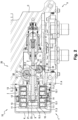
- the invention relates to a bistable electromagnetic actuator, generally designated 1, here controlling the movement of a distribution element 2 of an aircraft parking brake valve V between two service positions.
- the actuator 1 comprises, according to a particular embodiment of the invention, a fixed assembly generally designated by the reference 10, as well as a mobile assembly generally designated by the reference 20.
- the fixed assembly 10 has a generally cylindrical shape around a longitudinal axis , a set of four permanent magnets 14, two magnetic end pieces 15.1, 15.2 and a tube 16 of non-magnetic material.
- the frame 11 is made of ferromagnetic material and comprises a tubular body in two parts 11.1, 11.2 extending successively along the axis X. Each of the body parts 11.1, 11.2 is provided at its free end with a rim 11.3, 11.4 perpendicular to the axis X each defining an end opening of the carcass 11.
- the two coils 13 are each housed in an internal volume of the permanent magnet support 12 and are carried by said support to be centered on the axis X.
- Each coil 13 comprises two respective windings 13.1.
- the permanent magnet support 12 keeps the coils 13 spaced from one another and is trapped in the body parts 11.1, 11.2.
- the permanent magnet support 12 is made of ferromagnetic material.
- the permanent magnets 14 are symmetrically distributed around the axis
- the magnetic ends 15.1, 15.2 are coaxial with respect to the axis 11.3.
- the end piece 15.2 comprises a part extending projecting from the end opening defined by the rim 11.4.
- Each end piece 15.1, 15.2 has a tubular shape centered on the axis guided by the carcass 11 and the support 12 of permanent magnets.
- the tube 16 is centered on the axis
- the mobile assembly 20 comprises a core 21 made of ferromagnetic material and a non-magnetic rod 22 coupled to the core 21 to form an actuating member.
- the core 21 comprises a peripheral ring inside which extends radially a connecting web with the rod 22.
- the core 21 is able to slide along the axis X inside the tube 16 between two extreme positions in which said core 21 is partially facing the coils 13 and rests against one of the end pieces 15.1, 15.2.
- the end pieces 15.1, 15.2 thus form stops and also make it possible to close the magnetic flux of the coils 13 towards the core 21.
- the rod 22 has a generally cylindrical shape along the axis
- the rod 22 is thus movable along the axis X between a retracted position ( Figure 3 ) and an exit position ( Figure 4 ) corresponding to the extreme positions of core 21.
- the rod 22 passes axially through an opening made in the end piece 15.2 so that a distal end of the rod 22 extends projecting from the fixed assembly 10.
- the distal end of the rod 22 comprises a connection interface for be coupled to the distribution element 2, and is externally provided with a first annular groove 22.1 and a second groove 22.2.
- the fixed assembly 10 of the actuator is fixed integrally to a casing C of the valve V, via a fixing interface I made of non-magnetic material in which the carcass 11 is housed, so that the proximal end of the rod 22 extends inside a receiving volume L delimited by internal walls of the casing C.
- the fixed assembly 10 extends partly projecting from the fixing interface, which is itself partly in projecting from the casing C, and is covered by a cover K which is fixed to the fixing interface by extending projecting from the casing C.
- the actuator 1 also includes a manual control device 30 for manually moving the rod 22 between the retracted position and the extended position.
- the control device comprises a drive shaft 31 movable in rotation around an axis Y1 orthogonal to the axis exterior of the casing C.
- the end of the drive shaft 31 is provided with a lever 32 (visible on the figure 1 ) to rotate the drive shaft 31.
- the lever 32 here commonly called a “butterfly” shape, comprises two identical lugs 32.1, 32.2 which extend symmetrically on either side of the axis Y1 and in a plane passing through said axis Y1.
- the ears 32.1, 32.2 form gripping means for rotating the drive shaft 31.
- the drive shaft 31 comprises a tooth 31.1 engaged in the first groove 22.1 of the rod 22 so that a rotation of the drive shaft 31 around the axis Y1 causes a sliding of the rod 22 following the axis movement of the core 21 towards one or other of its extreme positions.
- the tooth 31.1 has a rounded shape and fits, when the drive shaft 31 pivots, in a cylinder centered on the axis Y1 and of diameter equal to an external diameter of the drive shaft 31.
- the lever 32 has an angular travel defined directly by the retracted position and the position of the rod 22, and indirectly by the extreme positions of the core 21. As illustrated in the figure 1 , this deflection angular is materialized by a first line T1 followed by the inscription “ON” and by a second line T2 followed by the inscription “OFF”.
- the first line T1 corresponds to an extreme angular position of the lever 32 in which the ear 32.1 is in the extension of said first line T1 and the rod 22 is in the extended position.
- the second line T2 corresponds to an extreme angular position of the lever 32 in which the ear 32.1 is in the extension of said second line T2 and the rod 22 is in the extended position.
- the lever 32 thus provides a visual indication of the position of the rod 22.
- the actuator 1 further comprises a feedback shaft 33 mounted in a wall of the casing C to have a movable end in rotation inside the volume L around an axis Y2 orthogonal to the axis X.
- the axes Y1, Y2 are parallel.
- the feedback shaft 33 and the drive shaft 31 extend on either side of the rod 22.
- the end of the copying shaft 33 comprises a tooth 33.1 engaged in the second groove 22.2 of the rod 22 so that sliding of the rod 22 along the axis of the Y2 axis.
- the tooth 33.1 has a rounded shape and fits, during the rotation of the feedback shaft 33, in a cylinder centered on the axis Y2 and of diameter equal to an external diameter of the feedback shaft 33.
- a permanent magnet 34 is fixed on an external surface of the feedback shaft 33 which is opposite the tooth 33.1, and a Hall effect sensor 35 is arranged inside the casing C so that the sensor 35 detects a magnetic field emitted by the magnet 34 when the feedback shaft 33 is in an angular position corresponding to the extended position of the rod 22.
- the sensor 35 is connected to an electronic unit (not shown here) allowing, for example , to go up to the level of the cockpit of the aircraft information relating to the position of the rod 22, and therefore to a state of the valve V.
- one of the two electromagnetic coils 13 is electrically powered so as to generate a magnetic field of attraction of the core 21.
- the other electromagnetic coil 13 n It is not electrically powered.
- the magnetic field generated by the coil 13 produces a magnetic flux which is guided by the ferromagnetic parts of the actuator 1.
- the magnetic flux forms a loop and successively passes through the end piece 15.1, 15.2 in contact with the electrically powered coil 13, the part 11.1, 11.2 of the carcass 11 in contact with said end piece 15.1, 15.2, the permanent magnet support 12, the permanent magnets 14 and the core 21.
- the core 21 then moves inside the tube 16 and is plated against the corresponding end piece 15.1, 15.2 of the fixed assembly 10.
- the core 21 is then separated from the other end piece 15.1, 15.2.
- the passage of the core 21 towards one or other of its extreme positions causes a sliding of the rod 22 towards the retracted position or the extended position, and therefore a movement of the distribution element 2 of the valve V between two positions in service.
- the sliding of the rod 22 in turn causes a rotation of the drive shaft 31 and a rotation of the feedback shaft 33.
- the angular position of the feedback shaft 33 is such that the permanent magnet 34 faces the sensor 35.
- the sensor 35 detects the magnetic field emitted by the magnet 34 , which allows the electronic unit to inform the pilot of the aircraft that the valve V is in a state corresponding to the extended position of the rod 22.
- the angular position of the feedback shaft 33 is such that the permanent magnet 34 is not facing the sensor 35.
- the sensor 35 then does not detect the magnetic field emitted by magnet 34.
- the drive shaft 31 and the feedback shaft 33 do not necessarily extend parallel to each other.
- drive shaft 31 and the feedback shaft 33 are on either side of the rod 22, they can also extend on the same side of the rod 22.
- the tooth 31.1 of the drive shaft 31 and the tooth 33.1 of the feedback shaft 33 can be engaged in one and the same groove 22.1.
- the distribution element 2 can for example be a valve or a drawer.
- the shape and dimensions of the rod 22 may be different from that described and illustrated.
- Each of the grooves can be replaced by at least one relief.
- Each of the grooves can be provided on the actuating member, the core or any other part linked in translation to the actuating member.
- the drive shaft can itself be provided with a magnet to also act as a feedback shaft.
- the invention can be used for any type of actuator regardless of the device operated.
Landscapes
- Engineering & Computer Science (AREA)
- Mechanical Engineering (AREA)
- Physics & Mathematics (AREA)
- Electromagnetism (AREA)
- General Engineering & Computer Science (AREA)
- Transportation (AREA)
- Power Engineering (AREA)
- Magnetically Actuated Valves (AREA)
- Electromagnets (AREA)
- Braking Arrangements (AREA)
Claims (7)
- Bistabiler elektromagnetischer Aktuator (1), umfassend:ein Gehäuse (11), das sich entlang einer Kraftachse (X) des Aktuators erstreckt;- zwei Anregungsspulen (13), die im Inneren des Gehäuses angeordnet sind und jeweils mindestens eine Wicklung (13.1) um die Kraftachse umfassen, um einen magnetischen Steuerfluss zu erzeugen;- einen Kern (21), der entlang der Kraftachse beweglich und geeignet ist, in zwei Endposition in Abhängigkeit des von den Spulen erzeugten magnetischen Flusses immobilisiert zu werden;- ein Betätigungsorgan (22), das mit dem Kern gekoppelt ist, um eine bewegliche Einheit (20) zu bilden; und- eine manuelle Steuervorrichtung (30),wobei der Aktuator dadurch gekennzeichnet ist, dass die Steuervorrichtung eine Antriebswelle (31) umfasst, die rotationsbeweglich um eine erste Achse (Y1) ist, die orthogonal zur Kraftachse ist, wobei die Antriebswelle mindestens einen Zahn (31.1) umfasst, der mit mindestens einem ersten Reliefelement (22.1) zusammenwirkt, das mit dem Betätigungsorgan derart in Translation verbunden ist, dass eine Drehung der Antriebswelle eine Translation der beweglichen Einheit erzeugt.
- Aktuator (1) nach Anspruch 1, bei dem das Betätigungsorgan eine Stange umfasst, die sich entlang der Kraftachse erstreckt.
- Aktuator (1) nach einem der vorhergehenden Ansprüche, bei dem die Steuervorrichtung (30) einen Hebel (32) umfasst, der an einem Ende der Antriebswelle (31) angeordnet ist, um die genannte Antriebswelle in Drehung anzutreiben.
- Aktuator (1) nach einem der vorhergehenden Ansprüche, ferner umfassend eine Kopierwelle (33), die drehbeweglich um eine zweite Achse (Y2) gelagert ist, die orthogonal zur Kraftachse (X) ist, wobei die Kopierwelle einen Zahn (33.1) umfasst, der mit dem mindestens einen Reliefelement (22.1) oder mit mindestens einem zweiten Reliefelement (22.2) des Betätigungselements (22) derart zusammenwirkt, dass eine Translation der beweglichen Einheit eine Drehung der Kopierwelle zur Folge hat.
- Aktuator (1) nach Anspruch 4, umfassend einen Dauermagneten (34), der von der Kopierwelle (33) getragen wird, und einen Hall-Effekt-Sensor (35), der ausgebildet ist, ein von dem Magneten emittiertes Magnetfeld zu erfassen, wenn die Kopierwelle in einer Winkelposition ist, die einer der Endpositionen des Kerns (21) entspricht.
- Parkbremsventil (V) für ein Luftfahrzeug, umfassend einen Aktuator (1) nach einem der vorhergehenden Ansprüche und ein Verteilungselement (2), das zwischen zwei Betriebspositionen beweglich ist, wobei das Betätigungsorgan (22) mit dem Verteilungselement verbunden ist, um eine Verschiebung des Verteilungselements zwischen zwei Betriebspositionen zu steuern.
- Ventil (V) nach Anspruch 6, bei dem das Verteilungselement (2) ein Klappenventil oder ein Schieber ist.
Applications Claiming Priority (2)
| Application Number | Priority Date | Filing Date | Title |
|---|---|---|---|
| FR2004471A FR3110025B1 (fr) | 2020-05-05 | 2020-05-05 | Actionneur électromagnétique à commande manuelle et valve de frein de parking équipée d’un tel actionneur |
| PCT/EP2021/061702 WO2021224241A1 (fr) | 2020-05-05 | 2021-05-04 | Actionneur electromagnetique a commande manuelle et valve de frein de parking equipee d'un tel actionneur |
Publications (2)
| Publication Number | Publication Date |
|---|---|
| EP4146509A1 EP4146509A1 (de) | 2023-03-15 |
| EP4146509B1 true EP4146509B1 (de) | 2024-07-17 |
Family
ID=72356074
Family Applications (1)
| Application Number | Title | Priority Date | Filing Date |
|---|---|---|---|
| EP21722893.1A Active EP4146509B1 (de) | 2020-05-05 | 2021-05-04 | Manuell betätigter elektromagnetischer aktuator und mit einem solchen aktuator ausgestattetes parkbremsventil |
Country Status (5)
| Country | Link |
|---|---|
| US (1) | US12038098B2 (de) |
| EP (1) | EP4146509B1 (de) |
| ES (1) | ES2989798T3 (de) |
| FR (1) | FR3110025B1 (de) |
| WO (1) | WO2021224241A1 (de) |
Family Cites Families (11)
| Publication number | Priority date | Publication date | Assignee | Title |
|---|---|---|---|---|
| US255162A (en) * | 1882-03-21 | Faucet | ||
| US780929A (en) * | 1904-03-18 | 1905-01-24 | William Angehr | Self-closing faucet. |
| US1177761A (en) * | 1914-11-18 | 1916-04-04 | James H Clemmer | Electrically-operated valve. |
| US1384443A (en) * | 1920-05-08 | 1921-07-12 | Brown Instr Co | Electro valve mechanism |
| US1822388A (en) * | 1929-07-15 | 1931-09-08 | Herbert G Beede | Steaming valve for garment presses |
| US3052828A (en) * | 1959-08-05 | 1962-09-04 | P S P Engineering Co | Rotary electromagnetic actuator |
| US5365210A (en) * | 1993-09-21 | 1994-11-15 | Alliedsignal Inc. | Latching solenoid with manual override |
| US5504468A (en) * | 1994-05-16 | 1996-04-02 | Kabushiki Kaisha Tokai Rika Denki Seisakusho | Electromagnetic solenoid |
| TW502096B (en) * | 2001-12-28 | 2002-09-11 | Ind Tech Res Inst | One-way returning electromagnetic valve |
| DE102010000737A1 (de) * | 2009-02-18 | 2010-08-19 | Continental Teves Ag & Co. Ohg | Elektromechanisch betätigbare Bremse |
| FR3116165A1 (fr) * | 2020-11-12 | 2022-05-13 | Safran Landing Systems | Actionneur électromagnétique rotatif à commande manuelle et valve de frein de parking équipée d’un tel actionneur |
-
2020
- 2020-05-05 FR FR2004471A patent/FR3110025B1/fr active Active
-
2021
- 2021-05-04 US US17/997,945 patent/US12038098B2/en active Active
- 2021-05-04 ES ES21722893T patent/ES2989798T3/es active Active
- 2021-05-04 WO PCT/EP2021/061702 patent/WO2021224241A1/fr not_active Ceased
- 2021-05-04 EP EP21722893.1A patent/EP4146509B1/de active Active
Also Published As
| Publication number | Publication date |
|---|---|
| ES2989798T3 (es) | 2024-11-27 |
| FR3110025A1 (fr) | 2021-11-12 |
| WO2021224241A1 (fr) | 2021-11-11 |
| EP4146509A1 (de) | 2023-03-15 |
| FR3110025B1 (fr) | 2022-05-06 |
| US12038098B2 (en) | 2024-07-16 |
| US20230175606A1 (en) | 2023-06-08 |
Similar Documents
| Publication | Publication Date | Title |
|---|---|---|
| EP1496601B1 (de) | Bremssystem mit sicherer Drehmomentaufnahme | |
| EP0862702B1 (de) | Elektromechanische reibkupplungsbetätigung für kraftfahrzeuge | |
| FR3115579A1 (fr) | Système d’entrainement différentiel, plus particulièrement destiné à être utilisé dans un groupe motopropulseur d'un véhicule automobile | |
| WO2019058044A1 (fr) | Module de détection d'une poignée rotative d'un véhicule motorise | |
| EP2148413B1 (de) | Integriertes lineares elektrisches Stellglied | |
| EP3099572B1 (de) | Rotationsblockierungsvorrichtung mit vereinfachter struktur und aktuatorvorrichtung mit solch einer vorrichtung | |
| EP4146509B1 (de) | Manuell betätigter elektromagnetischer aktuator und mit einem solchen aktuator ausgestattetes parkbremsventil | |
| EP2475557B1 (de) | Bedienungskolben für einen bremskraftverstärker und bremskraftverstärker der damit versehen ist | |
| EP1709655B1 (de) | Bistabile betätigungsvorrichtung einer bewegbaren, nicht durchgehenden, welle und damit versehener schalter für batterie | |
| EP4244962A1 (de) | Bistabiler elektromagnetischer aktuator und flugzeugbremsventil mit solch einem aktuator | |
| EP4259493B1 (de) | Aktuator mit integrierter feststellbremse | |
| EP1715564A2 (de) | Bremsvorrichtung für die Drehwelle eines Antriebs, wie ein Elektromotor | |
| EP2168867A1 (de) | Teleskopischer Stellantrieb mit Haupt- und Hilstriebstange | |
| EP1555463B1 (de) | Getriebesteuerungseinrichtung, insbesondere für Fahrzeuge | |
| EP4356023A1 (de) | Elektromagnetische betätigungsvorrichtung und übertragungssystem mit dieser elektromagnetischen betätigungsvorrichtung | |
| EP4253786B1 (de) | Elektromagnetische bremsvorrichtung, konfiguriert zum blockieren einer rotierenden welle, und mobilitätssystem, das die vorrichtung und die drehwelle besteht | |
| FR2853762A1 (fr) | Dispositif de manoeuvre bistable d'un arbre mobile en translation | |
| EP3569552B1 (de) | Steuervorrichtung eines ver-/entriegelungsorgans eines öffnungsflügels auf einem rahmen, wie einem riegel, und diese umfassendes schloss | |
| EP1845546A2 (de) | Bistabile Stellvorrichtung einer beweglichen Welle und Batteriestromunterbrecher mit einer solchen Vorrichtung | |
| FR3157490A1 (fr) | Frein magnétique à hystérésis à rappel élastique réduit | |
| WO2024236069A1 (fr) | Ensemble d'une roue et d'un arbre portant la roue, vehicule equipe d'un tel ensemble | |
| FR3133895A1 (fr) | Dispositif de freinage électromagnétique configuré pour bloquer un arbre rotatif et système de mobilité comportant le dispositif et l’arbre rotatif | |
| FR2877756A1 (fr) | Dispositif indicateur d'une manoeuvre aller et retour d'un element mobile, et dispositif de verrouillage equipe d'un tel dispositif indicateur | |
| WO2004088188A2 (fr) | Dispositif d'actionnement electromagnetique | |
| FR2828443A1 (fr) | Volant pour vehicule automobile |
Legal Events
| Date | Code | Title | Description |
|---|---|---|---|
| STAA | Information on the status of an ep patent application or granted ep patent |
Free format text: STATUS: UNKNOWN |
|
| STAA | Information on the status of an ep patent application or granted ep patent |
Free format text: STATUS: THE INTERNATIONAL PUBLICATION HAS BEEN MADE |
|
| PUAI | Public reference made under article 153(3) epc to a published international application that has entered the european phase |
Free format text: ORIGINAL CODE: 0009012 |
|
| STAA | Information on the status of an ep patent application or granted ep patent |
Free format text: STATUS: REQUEST FOR EXAMINATION WAS MADE |
|
| 17P | Request for examination filed |
Effective date: 20221107 |
|
| AK | Designated contracting states |
Kind code of ref document: A1 Designated state(s): AL AT BE BG CH CY CZ DE DK EE ES FI FR GB GR HR HU IE IS IT LI LT LU LV MC MK MT NL NO PL PT RO RS SE SI SK SM TR |
|
| DAV | Request for validation of the european patent (deleted) | ||
| DAX | Request for extension of the european patent (deleted) | ||
| GRAP | Despatch of communication of intention to grant a patent |
Free format text: ORIGINAL CODE: EPIDOSNIGR1 |
|
| STAA | Information on the status of an ep patent application or granted ep patent |
Free format text: STATUS: GRANT OF PATENT IS INTENDED |
|
| GRAJ | Information related to disapproval of communication of intention to grant by the applicant or resumption of examination proceedings by the epo deleted |
Free format text: ORIGINAL CODE: EPIDOSDIGR1 |
|
| STAA | Information on the status of an ep patent application or granted ep patent |
Free format text: STATUS: REQUEST FOR EXAMINATION WAS MADE |
|
| INTG | Intention to grant announced |
Effective date: 20231219 |
|
| INTC | Intention to grant announced (deleted) | ||
| GRAP | Despatch of communication of intention to grant a patent |
Free format text: ORIGINAL CODE: EPIDOSNIGR1 |
|
| STAA | Information on the status of an ep patent application or granted ep patent |
Free format text: STATUS: GRANT OF PATENT IS INTENDED |
|
| INTG | Intention to grant announced |
Effective date: 20240213 |
|
| GRAS | Grant fee paid |
Free format text: ORIGINAL CODE: EPIDOSNIGR3 |
|
| GRAA | (expected) grant |
Free format text: ORIGINAL CODE: 0009210 |
|
| STAA | Information on the status of an ep patent application or granted ep patent |
Free format text: STATUS: THE PATENT HAS BEEN GRANTED |
|
| AK | Designated contracting states |
Kind code of ref document: B1 Designated state(s): AL AT BE BG CH CY CZ DE DK EE ES FI FR GB GR HR HU IE IS IT LI LT LU LV MC MK MT NL NO PL PT RO RS SE SI SK SM TR |
|
| REG | Reference to a national code |
Ref country code: CH Ref legal event code: EP |
|
| REG | Reference to a national code |
Ref country code: DE Ref legal event code: R096 Ref document number: 602021015838 Country of ref document: DE |
|
| REG | Reference to a national code |
Ref country code: IE Ref legal event code: FG4D Free format text: LANGUAGE OF EP DOCUMENT: FRENCH |
|
| REG | Reference to a national code |
Ref country code: LT Ref legal event code: MG9D |
|
| REG | Reference to a national code |
Ref country code: NL Ref legal event code: MP Effective date: 20240717 |
|
| REG | Reference to a national code |
Ref country code: ES Ref legal event code: FG2A Ref document number: 2989798 Country of ref document: ES Kind code of ref document: T3 Effective date: 20241127 |
|
| PG25 | Lapsed in a contracting state [announced via postgrant information from national office to epo] |
Ref country code: PT Free format text: LAPSE BECAUSE OF FAILURE TO SUBMIT A TRANSLATION OF THE DESCRIPTION OR TO PAY THE FEE WITHIN THE PRESCRIBED TIME-LIMIT Effective date: 20241118 |
|
| REG | Reference to a national code |
Ref country code: AT Ref legal event code: MK05 Ref document number: 1703838 Country of ref document: AT Kind code of ref document: T Effective date: 20240717 |
|
| PG25 | Lapsed in a contracting state [announced via postgrant information from national office to epo] |
Ref country code: NL Free format text: LAPSE BECAUSE OF FAILURE TO SUBMIT A TRANSLATION OF THE DESCRIPTION OR TO PAY THE FEE WITHIN THE PRESCRIBED TIME-LIMIT Effective date: 20240717 |
|
| PG25 | Lapsed in a contracting state [announced via postgrant information from national office to epo] |
Ref country code: PT Free format text: LAPSE BECAUSE OF FAILURE TO SUBMIT A TRANSLATION OF THE DESCRIPTION OR TO PAY THE FEE WITHIN THE PRESCRIBED TIME-LIMIT Effective date: 20241118 Ref country code: NL Free format text: LAPSE BECAUSE OF FAILURE TO SUBMIT A TRANSLATION OF THE DESCRIPTION OR TO PAY THE FEE WITHIN THE PRESCRIBED TIME-LIMIT Effective date: 20240717 |
|
| PG25 | Lapsed in a contracting state [announced via postgrant information from national office to epo] |
Ref country code: NO Free format text: LAPSE BECAUSE OF FAILURE TO SUBMIT A TRANSLATION OF THE DESCRIPTION OR TO PAY THE FEE WITHIN THE PRESCRIBED TIME-LIMIT Effective date: 20241017 |
|
| PG25 | Lapsed in a contracting state [announced via postgrant information from national office to epo] |
Ref country code: GR Free format text: LAPSE BECAUSE OF FAILURE TO SUBMIT A TRANSLATION OF THE DESCRIPTION OR TO PAY THE FEE WITHIN THE PRESCRIBED TIME-LIMIT Effective date: 20241018 Ref country code: FI Free format text: LAPSE BECAUSE OF FAILURE TO SUBMIT A TRANSLATION OF THE DESCRIPTION OR TO PAY THE FEE WITHIN THE PRESCRIBED TIME-LIMIT Effective date: 20240717 Ref country code: PL Free format text: LAPSE BECAUSE OF FAILURE TO SUBMIT A TRANSLATION OF THE DESCRIPTION OR TO PAY THE FEE WITHIN THE PRESCRIBED TIME-LIMIT Effective date: 20240717 |
|
| PG25 | Lapsed in a contracting state [announced via postgrant information from national office to epo] |
Ref country code: BG Free format text: LAPSE BECAUSE OF FAILURE TO SUBMIT A TRANSLATION OF THE DESCRIPTION OR TO PAY THE FEE WITHIN THE PRESCRIBED TIME-LIMIT Effective date: 20240717 |
|
| PG25 | Lapsed in a contracting state [announced via postgrant information from national office to epo] |
Ref country code: LV Free format text: LAPSE BECAUSE OF FAILURE TO SUBMIT A TRANSLATION OF THE DESCRIPTION OR TO PAY THE FEE WITHIN THE PRESCRIBED TIME-LIMIT Effective date: 20240717 |
|
| PG25 | Lapsed in a contracting state [announced via postgrant information from national office to epo] |
Ref country code: IS Free format text: LAPSE BECAUSE OF FAILURE TO SUBMIT A TRANSLATION OF THE DESCRIPTION OR TO PAY THE FEE WITHIN THE PRESCRIBED TIME-LIMIT Effective date: 20241117 Ref country code: AT Free format text: LAPSE BECAUSE OF FAILURE TO SUBMIT A TRANSLATION OF THE DESCRIPTION OR TO PAY THE FEE WITHIN THE PRESCRIBED TIME-LIMIT Effective date: 20240717 |
|
| PG25 | Lapsed in a contracting state [announced via postgrant information from national office to epo] |
Ref country code: HR Free format text: LAPSE BECAUSE OF FAILURE TO SUBMIT A TRANSLATION OF THE DESCRIPTION OR TO PAY THE FEE WITHIN THE PRESCRIBED TIME-LIMIT Effective date: 20240717 |
|
| PG25 | Lapsed in a contracting state [announced via postgrant information from national office to epo] |
Ref country code: RS Free format text: LAPSE BECAUSE OF FAILURE TO SUBMIT A TRANSLATION OF THE DESCRIPTION OR TO PAY THE FEE WITHIN THE PRESCRIBED TIME-LIMIT Effective date: 20241017 |
|
| PG25 | Lapsed in a contracting state [announced via postgrant information from national office to epo] |
Ref country code: RS Free format text: LAPSE BECAUSE OF FAILURE TO SUBMIT A TRANSLATION OF THE DESCRIPTION OR TO PAY THE FEE WITHIN THE PRESCRIBED TIME-LIMIT Effective date: 20241017 Ref country code: PL Free format text: LAPSE BECAUSE OF FAILURE TO SUBMIT A TRANSLATION OF THE DESCRIPTION OR TO PAY THE FEE WITHIN THE PRESCRIBED TIME-LIMIT Effective date: 20240717 Ref country code: NO Free format text: LAPSE BECAUSE OF FAILURE TO SUBMIT A TRANSLATION OF THE DESCRIPTION OR TO PAY THE FEE WITHIN THE PRESCRIBED TIME-LIMIT Effective date: 20241017 Ref country code: LV Free format text: LAPSE BECAUSE OF FAILURE TO SUBMIT A TRANSLATION OF THE DESCRIPTION OR TO PAY THE FEE WITHIN THE PRESCRIBED TIME-LIMIT Effective date: 20240717 Ref country code: IS Free format text: LAPSE BECAUSE OF FAILURE TO SUBMIT A TRANSLATION OF THE DESCRIPTION OR TO PAY THE FEE WITHIN THE PRESCRIBED TIME-LIMIT Effective date: 20241117 Ref country code: HR Free format text: LAPSE BECAUSE OF FAILURE TO SUBMIT A TRANSLATION OF THE DESCRIPTION OR TO PAY THE FEE WITHIN THE PRESCRIBED TIME-LIMIT Effective date: 20240717 Ref country code: GR Free format text: LAPSE BECAUSE OF FAILURE TO SUBMIT A TRANSLATION OF THE DESCRIPTION OR TO PAY THE FEE WITHIN THE PRESCRIBED TIME-LIMIT Effective date: 20241018 Ref country code: FI Free format text: LAPSE BECAUSE OF FAILURE TO SUBMIT A TRANSLATION OF THE DESCRIPTION OR TO PAY THE FEE WITHIN THE PRESCRIBED TIME-LIMIT Effective date: 20240717 Ref country code: BG Free format text: LAPSE BECAUSE OF FAILURE TO SUBMIT A TRANSLATION OF THE DESCRIPTION OR TO PAY THE FEE WITHIN THE PRESCRIBED TIME-LIMIT Effective date: 20240717 Ref country code: AT Free format text: LAPSE BECAUSE OF FAILURE TO SUBMIT A TRANSLATION OF THE DESCRIPTION OR TO PAY THE FEE WITHIN THE PRESCRIBED TIME-LIMIT Effective date: 20240717 |
|
| PG25 | Lapsed in a contracting state [announced via postgrant information from national office to epo] |
Ref country code: SM Free format text: LAPSE BECAUSE OF FAILURE TO SUBMIT A TRANSLATION OF THE DESCRIPTION OR TO PAY THE FEE WITHIN THE PRESCRIBED TIME-LIMIT Effective date: 20240717 Ref country code: RO Free format text: LAPSE BECAUSE OF FAILURE TO SUBMIT A TRANSLATION OF THE DESCRIPTION OR TO PAY THE FEE WITHIN THE PRESCRIBED TIME-LIMIT Effective date: 20240717 Ref country code: DK Free format text: LAPSE BECAUSE OF FAILURE TO SUBMIT A TRANSLATION OF THE DESCRIPTION OR TO PAY THE FEE WITHIN THE PRESCRIBED TIME-LIMIT Effective date: 20240717 |
|
| REG | Reference to a national code |
Ref country code: DE Ref legal event code: R097 Ref document number: 602021015838 Country of ref document: DE |
|
| PG25 | Lapsed in a contracting state [announced via postgrant information from national office to epo] |
Ref country code: EE Free format text: LAPSE BECAUSE OF FAILURE TO SUBMIT A TRANSLATION OF THE DESCRIPTION OR TO PAY THE FEE WITHIN THE PRESCRIBED TIME-LIMIT Effective date: 20240717 |
|
| PG25 | Lapsed in a contracting state [announced via postgrant information from national office to epo] |
Ref country code: CZ Free format text: LAPSE BECAUSE OF FAILURE TO SUBMIT A TRANSLATION OF THE DESCRIPTION OR TO PAY THE FEE WITHIN THE PRESCRIBED TIME-LIMIT Effective date: 20240717 |
|
| PG25 | Lapsed in a contracting state [announced via postgrant information from national office to epo] |
Ref country code: SK Free format text: LAPSE BECAUSE OF FAILURE TO SUBMIT A TRANSLATION OF THE DESCRIPTION OR TO PAY THE FEE WITHIN THE PRESCRIBED TIME-LIMIT Effective date: 20240717 |
|
| PLBE | No opposition filed within time limit |
Free format text: ORIGINAL CODE: 0009261 |
|
| STAA | Information on the status of an ep patent application or granted ep patent |
Free format text: STATUS: NO OPPOSITION FILED WITHIN TIME LIMIT |
|
| 26N | No opposition filed |
Effective date: 20250422 |
|
| PGFP | Annual fee paid to national office [announced via postgrant information from national office to epo] |
Ref country code: DE Payment date: 20250519 Year of fee payment: 5 |
|
| PGFP | Annual fee paid to national office [announced via postgrant information from national office to epo] |
Ref country code: GB Payment date: 20250527 Year of fee payment: 5 Ref country code: ES Payment date: 20250616 Year of fee payment: 5 |
|
| PGFP | Annual fee paid to national office [announced via postgrant information from national office to epo] |
Ref country code: FR Payment date: 20250526 Year of fee payment: 5 |
|
| PG25 | Lapsed in a contracting state [announced via postgrant information from national office to epo] |
Ref country code: SE Free format text: LAPSE BECAUSE OF FAILURE TO SUBMIT A TRANSLATION OF THE DESCRIPTION OR TO PAY THE FEE WITHIN THE PRESCRIBED TIME-LIMIT Effective date: 20240717 |
|
| REG | Reference to a national code |
Ref country code: CH Ref legal event code: H13 Free format text: ST27 STATUS EVENT CODE: U-0-0-H10-H13 (AS PROVIDED BY THE NATIONAL OFFICE) Effective date: 20251223 |
|
| PG25 | Lapsed in a contracting state [announced via postgrant information from national office to epo] |
Ref country code: LU Free format text: LAPSE BECAUSE OF NON-PAYMENT OF DUE FEES Effective date: 20250504 |
|
| PG25 | Lapsed in a contracting state [announced via postgrant information from national office to epo] |
Ref country code: CH Free format text: LAPSE BECAUSE OF NON-PAYMENT OF DUE FEES Effective date: 20250531 |
|
| PG25 | Lapsed in a contracting state [announced via postgrant information from national office to epo] |
Ref country code: IT Free format text: LAPSE BECAUSE OF FAILURE TO SUBMIT A TRANSLATION OF THE DESCRIPTION OR TO PAY THE FEE WITHIN THE PRESCRIBED TIME-LIMIT Effective date: 20240717 |
|
| REG | Reference to a national code |
Ref country code: BE Ref legal event code: MM Effective date: 20250531 |
|
| PG25 | Lapsed in a contracting state [announced via postgrant information from national office to epo] |
Ref country code: MC Free format text: LAPSE BECAUSE OF FAILURE TO SUBMIT A TRANSLATION OF THE DESCRIPTION OR TO PAY THE FEE WITHIN THE PRESCRIBED TIME-LIMIT Effective date: 20240717 |
|
| PG25 | Lapsed in a contracting state [announced via postgrant information from national office to epo] |
Ref country code: IE Free format text: LAPSE BECAUSE OF NON-PAYMENT OF DUE FEES Effective date: 20250504 |
|
| PG25 | Lapsed in a contracting state [announced via postgrant information from national office to epo] |
Ref country code: BE Free format text: LAPSE BECAUSE OF NON-PAYMENT OF DUE FEES Effective date: 20250531 |