EP4151442B1 - Système de montage de réservoir de combustible d'hydrogène - Google Patents
Système de montage de réservoir de combustible d'hydrogène Download PDFInfo
- Publication number
- EP4151442B1 EP4151442B1 EP21198143.6A EP21198143A EP4151442B1 EP 4151442 B1 EP4151442 B1 EP 4151442B1 EP 21198143 A EP21198143 A EP 21198143A EP 4151442 B1 EP4151442 B1 EP 4151442B1
- Authority
- EP
- European Patent Office
- Prior art keywords
- mount
- fuel tank
- body portion
- aperture
- cap
- Prior art date
- Legal status (The legal status is an assumption and is not a legal conclusion. Google has not performed a legal analysis and makes no representation as to the accuracy of the status listed.)
- Active
Links
Images


Classifications
-
- B—PERFORMING OPERATIONS; TRANSPORTING
- B60—VEHICLES IN GENERAL
- B60K—ARRANGEMENT OR MOUNTING OF PROPULSION UNITS OR OF TRANSMISSIONS IN VEHICLES; ARRANGEMENT OR MOUNTING OF PLURAL DIVERSE PRIME-MOVERS IN VEHICLES; AUXILIARY DRIVES FOR VEHICLES; INSTRUMENTATION OR DASHBOARDS FOR VEHICLES; ARRANGEMENTS IN CONNECTION WITH COOLING, AIR INTAKE, GAS EXHAUST OR FUEL SUPPLY OF PROPULSION UNITS IN VEHICLES
- B60K15/00—Arrangement in connection with fuel supply of combustion engines or other fuel consuming energy converters, e.g. fuel cells; Mounting or construction of fuel tanks
- B60K15/03—Fuel tanks
- B60K15/03006—Gas tanks
-
- B—PERFORMING OPERATIONS; TRANSPORTING
- B60—VEHICLES IN GENERAL
- B60K—ARRANGEMENT OR MOUNTING OF PROPULSION UNITS OR OF TRANSMISSIONS IN VEHICLES; ARRANGEMENT OR MOUNTING OF PLURAL DIVERSE PRIME-MOVERS IN VEHICLES; AUXILIARY DRIVES FOR VEHICLES; INSTRUMENTATION OR DASHBOARDS FOR VEHICLES; ARRANGEMENTS IN CONNECTION WITH COOLING, AIR INTAKE, GAS EXHAUST OR FUEL SUPPLY OF PROPULSION UNITS IN VEHICLES
- B60K15/00—Arrangement in connection with fuel supply of combustion engines or other fuel consuming energy converters, e.g. fuel cells; Mounting or construction of fuel tanks
- B60K15/03—Fuel tanks
- B60K15/063—Arrangement of tanks
- B60K15/067—Mounting of tanks
- B60K15/07—Mounting of tanks of gas tanks
-
- B—PERFORMING OPERATIONS; TRANSPORTING
- B60—VEHICLES IN GENERAL
- B60K—ARRANGEMENT OR MOUNTING OF PROPULSION UNITS OR OF TRANSMISSIONS IN VEHICLES; ARRANGEMENT OR MOUNTING OF PLURAL DIVERSE PRIME-MOVERS IN VEHICLES; AUXILIARY DRIVES FOR VEHICLES; INSTRUMENTATION OR DASHBOARDS FOR VEHICLES; ARRANGEMENTS IN CONNECTION WITH COOLING, AIR INTAKE, GAS EXHAUST OR FUEL SUPPLY OF PROPULSION UNITS IN VEHICLES
- B60K15/00—Arrangement in connection with fuel supply of combustion engines or other fuel consuming energy converters, e.g. fuel cells; Mounting or construction of fuel tanks
- B60K15/03—Fuel tanks
- B60K15/063—Arrangement of tanks
- B60K15/067—Mounting of tanks
-
- B—PERFORMING OPERATIONS; TRANSPORTING
- B60—VEHICLES IN GENERAL
- B60K—ARRANGEMENT OR MOUNTING OF PROPULSION UNITS OR OF TRANSMISSIONS IN VEHICLES; ARRANGEMENT OR MOUNTING OF PLURAL DIVERSE PRIME-MOVERS IN VEHICLES; AUXILIARY DRIVES FOR VEHICLES; INSTRUMENTATION OR DASHBOARDS FOR VEHICLES; ARRANGEMENTS IN CONNECTION WITH COOLING, AIR INTAKE, GAS EXHAUST OR FUEL SUPPLY OF PROPULSION UNITS IN VEHICLES
- B60K15/00—Arrangement in connection with fuel supply of combustion engines or other fuel consuming energy converters, e.g. fuel cells; Mounting or construction of fuel tanks
- B60K15/03—Fuel tanks
- B60K2015/03309—Tanks specially adapted for particular fuels
- B60K2015/03315—Tanks specially adapted for particular fuels for hydrogen
-
- Y—GENERAL TAGGING OF NEW TECHNOLOGICAL DEVELOPMENTS; GENERAL TAGGING OF CROSS-SECTIONAL TECHNOLOGIES SPANNING OVER SEVERAL SECTIONS OF THE IPC; TECHNICAL SUBJECTS COVERED BY FORMER USPC CROSS-REFERENCE ART COLLECTIONS [XRACs] AND DIGESTS
- Y02—TECHNOLOGIES OR APPLICATIONS FOR MITIGATION OR ADAPTATION AGAINST CLIMATE CHANGE
- Y02E—REDUCTION OF GREENHOUSE GAS [GHG] EMISSIONS, RELATED TO ENERGY GENERATION, TRANSMISSION OR DISTRIBUTION
- Y02E60/00—Enabling technologies; Technologies with a potential or indirect contribution to GHG emissions mitigation
- Y02E60/30—Hydrogen technology
- Y02E60/32—Hydrogen storage
Definitions
- the present disclosure concerns a system for mounting a hydrogen fuel tank in a vehicle, a hydrogen fuel system, and a vehicle that include such a mounting system, and a method of assembling such a hydrogen fuel system for attachment to a vehicle.
- WO 2020/243611 A1 describes a mounting system for a fuel tank.
- the fuel tank has a first boss at its first end and a second boss at its second end.
- a fixed bearing block assembly that includes two rigid block members supports the fuel tank at the second boss.
- Another bearing block assembly that includes two block portions is configured to permit some movement between its inner periphery and the first boss of the fuel tank.
- the first mount may be configured to mount a first elongated neck portion of a dual port fuel tank, directly or indirectly, to a vehicle chassis
- the second mount may be configured to slidably mount a second elongated neck portion of the dual port fuel tank to the vehicle chassis.
- the second mount allows movement of at least part of the second portion of the fuel tank, stresses on fuel pipes connected to the fuel tank, the first and second mounts, and other vehicle components may be reduced. This can, in turn, improve durability of the fuel system and vehicle and/or allow for reduced manufacturing tolerances.
- the first mount comprises a body portion and a cap portion that, when attached together, form an aperture to receive the first portion of the fuel tank, connected together by at least one fastener.
- the fastener is configured to attach the body portion to the cap portion with a clearance between the body portion and the cap portion. Such a clearance may reduce shear forces exerted on the first mount that would otherwise be experienced at an interface between the body portion and the cap portion, for example, in response to expansion or contraction of the fuel tank or shocks arising from sudden changes in motion of a vehicle.
- a sleeve is provided around at least part of the fastener to increase a region of the first mount over which such shear forces are distributed.
- a sleeve e.g., a hollow dowel, that extends through at least a part of the body portion and at least a part of the cap portion.
- the second mount provides an aperture to receive the second portion of the fuel tank, configured to allow sliding motion of the at least part of the second portion of the fuel tank through the aperture.
- An insert surrounds an inner surface of the aperture, formed of a material that provides surface along which the second portion can slide with reduced friction. The provision of a relative low friction surface improves the effectiveness with which the sliding motion and, therefore, the expansion and contraction of the fuel tank, is accommodated, as well as reducing wear on the second portion.
- the insert includes a circumferential groove configured to receive the inner surface of the aperture.
- the second mount comprises a body portion and a cap portion that, when attached together, are arranged to receive the second portion of the fuel tank, and at least one fastener that attaches the body portion of the second mount to the cap portion of the second mount.
- the body portion and the cap portion of the second mount may be attached to one another using one or more bolts.
- Such fasteners can assist in reducing forces arising from sudden changes in the motion of the vehicle, improving the durability of the mounting system, fuel system and vehicle.
- a hydrogen fuel system comprising a fuel tank configured to store gaseous fuel, and a mounting system according to the first aspect.
- the fuel tank may be a dual port fuel tank with first and second elongated neck portions, where the first mount receives the first elongated neck portion and the second mount receives the second elongated neck portion.
- a vehicle including the above mounting system and/or hydrogen fuel system.
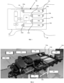
- a fuel system 100 is mounted in a cradle 102 and attached to a vehicle chassis 104.
- the fuel system 100 includes four hydrogen fuel tanks 106a-d arranged to supply hydrogen gas to a fuel cell 108.
- the fuel system 100 also includes batteries 110, 112, inverter 114, distribution unit 116.
- the fuel tanks 106a-d are attached to the cradle 102 by respective first and second mounts.
- fuel tank 106a is attached by first mount 118a and second mount 120a.
- Figure 2 is a view of the cradle 102 with the fuel tanks 106a-106d removed, allowing the first mounts 118a-d for respective fuel tanks 106a-d and the second mount 120c for fuel tank 106c to be shown more clearly.
- Figures 3 and 4 depict one of the fuel tanks 106a of the fuel system 100.
- the fuel tank 106a is a dual port fuel tank including first and second elongated neck portions 122, 124.
- the first elongated neck portion 122 is attached to the chassis 104 via the cradle 102 and the first mount 118a, while the second elongated neck portion 124 is attached to the chassis 104 via the cradle 102 and the second mount 120a.
- the first and second mounts 118a, 120a each include an aperture 126, 128 configured to receive respective ones of the neck portions 122, 124 of the fuel tank 106a.
- the first mount 118a is configured to hold the first elongated neck portion 122 in a fixed position, while the second mount 120a is configured to allow sliding motion of the second elongated neck portion 124 through the aperture 128, along the x direction indicated in Figure 3 .
- the hydrogen fuel tank 106a may expand while being filled. An expansion of the fuel tank 106a will cause sliding motion of the second neck portion 124 through the aperture 128 of the second mount 120a along the negative x direction, while the first neck portion 122 remains fixed in position by the first mount 118a. Such sliding motion of part of the fuel tank 106a allows the expansion of the fuel tank 106a to be accommodated within the fuel system 100 with reduced stress on the components of the fuel system 100, when compared with systems using only fixed mountings.
- contraction of the fuel tank 106a as the amount of hydrogen stored in the fuel tank 106a decreases causes sliding motion of the second neck portion 124 through the aperture 128 in the positive x direction, allowing the contraction to be accommodated with limited stress on the components of the fuel system 100.
- Figure 5 depicts an example first mount 118a for use in the fuel system 100 of Figure 1 , where a portion of the first mount 118a on the left of Figure 5 is shown in section.
- the first mount 118a includes a body portion 130 and a cap portion 132, which form the aperture 126 when attached together by at least one fastener.
- the body portion 130 and cap portion 132 are attached together by one or more bolts 134a that extend through at least part of the body portion 130 and at least part of the cap portion 132.
- the fastener is configured to provide a clearance 136 between adjacent surfaces of the body portion 130 and cap portion 132 when attached together. Such a clearance may reduce the effect of shear forces that would be present at the interface between the body portion 130 and cap portion 132 if their adjacent surfaces were in contact, or close contact, e.g., when clamping one end of the fuel tank to the vehicle.
- a sleeve 138 is provided around each fastener and extends into at least a part of the body portion 130 and at least a part of the cap portion 132.
- a sleeve 138 such as a hollow dowel, is provided around a part of a shaft 140 of each bolt 134a.
- Such a sleeve 138 can distribute any shear forces experienced by the bolt 134a along its shaft 140, e.g., due to loading of the cap portion 132 relative to the body portion 130.
- the clearance 136 and the sleeve 138 can limit localisation of stresses on at least one of the fastener, the body portion 130 and cap portion 132, improving the durability of the first mount 118a.
- the first mount 118a may be attached to the cradle 102 using bolts 142a, 142b or other fasteners. In other examples, the first mount 118a may be attached directly to the chassis 104 and/or to another part of a vehicle.
- Figure 6 depicts an example second mount 120a for use in the fuel system 100 of Figure 1 , where a portion of the second mount 120a on the right of Figure 6 is shown in section.
- the second mount 120a includes a body portion 144 and a cap portion 146, which form the aperture 128 when attached together.
- the body portion 144 and cap portion 146 are attached together by at least one fastener.
- the at least one fastener includes a bolt 148a that extends through at least part of the body portion 144 and at least part of the cap portion 146 of the second mount 120a, to clamp the body portion 144 and the cap portion 146 together.
- the second mount 120a may be attached to the cradle 102, the chassis 104, or another part of a vehicle, using fasteners such as bolts 150a, 150b.
- An insert 152 is provided that surrounds an inner surface of the aperture 128.
- the insert 152 may be formed of a material that reduces friction when the second neck portion 124 of the fuel tank 106a slides through the aperture 128.
- the insert 152 is formed of a plastics material.
- the insert 152 includes a circumferential groove 154, configured to receive the inner surface of the aperture 128. Because the inner surface of the aperture 128 is located within the groove 154, contact between the inner surfaces of the groove 154 and sides of the body portion 144 and the cap portion 146 resists motion of the insert 152 along the x direction. In this manner, the insert 152 is held in position when the second neck portion 124 is sliding through the aperture 128.
- the body portion 144 and the cap portion may be sized to ensure that tightening of a fastener, e.g., bolt 148a, does not substantially deform, e.g., by more than 10 microns or 100 microns, an inner opening of the insert 152 upon clamping the body portion 144 and the cap portion 146 together. In this manner, excessive clamping force is not applied to a portion of the fuel tank that is secured in the second mount 120a.
- a fastener e.g., bolt 148a
- FIG 8 shows an example of a vehicle 800 in which the fuel system may be installed.
- the vehicle 800 includes the fuel system 100 described above with reference to Figure 1 , located in the cradle 102 and attached to the underside of the chassis 104.
- the fuel system 100 may be attached, directly or indirectly, to the chassis 104 or to another part of the vehicle.
- the mounting system described above may be used to mount fuel tanks in other vehicles, including vans, trucks, coaches, buses, trucks, lorries, or any other appropriate vehicle. In some examples the mounting system described above may be used to mount fuel tanks in other applications, such as power generators, etc.
Landscapes
- Engineering & Computer Science (AREA)
- Life Sciences & Earth Sciences (AREA)
- Sustainable Development (AREA)
- Sustainable Energy (AREA)
- Chemical & Material Sciences (AREA)
- Combustion & Propulsion (AREA)
- Transportation (AREA)
- Mechanical Engineering (AREA)
- Cooling, Air Intake And Gas Exhaust, And Fuel Tank Arrangements In Propulsion Units (AREA)
Claims (8)
- Système de montage de réservoir de combustible, comprenant :
un premier support (118a) conçu pour fixer une première partie du réservoir de combustible (106a) dans une position fixe sur un véhicule, le premier support (118a) comprenant :une partie corps (130) et une partie chapeau (132) qui, lorsqu'elles sont fixées, forment une ouverture (126) pour recevoir la première partie du réservoir de combustible ;au moins un dispositif de fixation (134a) pour fixer la partie corps à la partie chapeau,dans lequel un dégagement (136) est maintenu entre la partie corps et la partie chapeau dans une configuration assemblée ; etun manchon (138) situé autour d'au moins une partie du dispositif de fixation ; etun second support (120a) conçu pour fixer une seconde partie du réservoir de combustible (106a) sur le véhicule et pour permettre le déplacement d'au moins une partie de la seconde partie par rapport au véhicule, le second support (120a) comprenant :une partie corps (144) et une partie chapeau (146) qui, lorsqu'elles sont fixées, forment une ouverture (128) pour recevoir la seconde partie du réservoir de combustible ;un insert (152) qui entoure une surface interne de l'ouverture suite au serrage de la partie corps et de la partie chapeau ensemble, l'insert comprenant une rainure circonférentielle (154) conçue pour recevoir la surface interne de l'ouverture ; etau moins un dispositif de fixation (148a) pour serrer ensemble la partie corps et la partie chapeau. - Système de montage selon la revendication 1, dans lequel le premier support est un support de fixation comprenant :la partie corps et la partie chapeau qui, lorsqu'elles sont fixées ensemble, forment l'ouverture pour recevoir la première partie du réservoir de combustible ;l'au moins un dispositif de fixation fixant la partie corps à la partie chapeau ; etle manchon entourant au moins une partie du ou des dispositifs de fixation et s'étendant à travers au moins une partie de la partie corps et au moins une partie de la partie chapeau.
- Système de montage selon la revendication 2, dans lequel lorsque la partie corps est fixée à la partie chapeau, des surfaces adjacentes de la partie corps et de la partie chapeau sont séparées par le dégagement.
- Système de montage selon l'une quelconque des revendications précédentes, dans lequel le second support comprend :
l'ouverture conçue pour recevoir la seconde partie du réservoir de combustible et permettre le coulissement de la seconde partie à travers l'ouverture. - Système de montage selon l'une quelconque des revendications précédentes, dans lequel le second support est un support de fixation comprenant :la partie corps et la partie chapeau qui, lorsqu'elles sont fixées ensemble, sont agencées pour recevoir la seconde partie du réservoir de combustible ; etle ou les dispositifs de fixation qui fixent la partie corps du second support à la partie chapeau du second support.
- Système de combustible comprenant :un réservoir de combustible à double orifice (106a) conçu pour stocker du combustible gazeux ; etle système de montage selon l'une quelconque des revendications précédentes ;dans lequel :la première partie est une première partie de col allongé du réservoir de combustible ; etla seconde partie est une seconde partie de col allongé du réservoir de combustible.
- Véhicule comprenant un système de combustible selon la revendication 6.
- Procédé d'assemblage d'un système de combustible, comprenant :
la fixation d'un premier support (118a) à une position fixe sur une première partie de col allongé d'un réservoir de combustible à double orifice (106a), le premier support (118a) comprenant :une partie corps (130) et une partie chapeau (132) qui, lorsqu'elles sont fixées, forment une ouverture (126) pour recevoir la première partie du réservoir de combustible ;au moins un dispositif de fixation (134a) pour fixer la partie corps à la partie chapeau,dans lequel un dégagement (136) est maintenu entre la partie corps et la partie chapeau dans une configuration assemblée ; etun manchon (138) situé autour d'au moins une partie du dispositif de fixation ; etla fixation d'un second support (120a) sur une seconde partie de col allongé du réservoir de combustible à double orifice (106a),dans lequel le second support permet le déplacement coulissant d'une partie de la seconde partie de col allongé à travers le second support, le second support (120a) comprenant :une partie corps (144) et une partie chapeau (146) qui, lorsqu'elles sont fixées, forment une ouverture (128) pour recevoir la seconde partie du réservoir de combustible ;un insert (152) qui entoure une surface interne de l'ouverture suite au serrage de la partie corps et de la partie chapeau ensemble, l'insert comprenant une rainure circonférentielle (154) conçue pour recevoir la surface interne de l'ouverture ; etau moins un dispositif de fixation (148a) pour serrer ensemble la partie corps et la partie chapeau ; etla fixation des premier et second supports sur un véhicule.
Priority Applications (3)
| Application Number | Priority Date | Filing Date | Title |
|---|---|---|---|
| EP21198143.6A EP4151442B1 (fr) | 2021-09-21 | 2021-09-21 | Système de montage de réservoir de combustible d'hydrogène |
| CN202211127120.9A CN115837847A (zh) | 2021-09-21 | 2022-09-16 | 氢燃料罐安装系统 |
| US17/949,425 US12434554B2 (en) | 2021-09-21 | 2022-09-21 | Hydrogen fuel tank mounting system |
Applications Claiming Priority (1)
| Application Number | Priority Date | Filing Date | Title |
|---|---|---|---|
| EP21198143.6A EP4151442B1 (fr) | 2021-09-21 | 2021-09-21 | Système de montage de réservoir de combustible d'hydrogène |
Publications (2)
| Publication Number | Publication Date |
|---|---|
| EP4151442A1 EP4151442A1 (fr) | 2023-03-22 |
| EP4151442B1 true EP4151442B1 (fr) | 2024-10-09 |
Family
ID=77897521
Family Applications (1)
| Application Number | Title | Priority Date | Filing Date |
|---|---|---|---|
| EP21198143.6A Active EP4151442B1 (fr) | 2021-09-21 | 2021-09-21 | Système de montage de réservoir de combustible d'hydrogène |
Country Status (3)
| Country | Link |
|---|---|
| US (1) | US12434554B2 (fr) |
| EP (1) | EP4151442B1 (fr) |
| CN (1) | CN115837847A (fr) |
Families Citing this family (1)
| Publication number | Priority date | Publication date | Assignee | Title |
|---|---|---|---|---|
| US12607306B2 (en) | 2023-06-15 | 2026-04-21 | Hexagon Purus Germany Holding Gmbh | Sliding vessel mount |
Family Cites Families (7)
| Publication number | Priority date | Publication date | Assignee | Title |
|---|---|---|---|---|
| CA2386443C (fr) * | 2001-05-17 | 2007-10-23 | Dynetek Industries Ltd. | Module d'alimentation en carburant remplacable et methode de remplacement |
| DE102012011612A1 (de) * | 2012-06-12 | 2013-01-31 | Daimler Ag | Speichervorrichtung zum Speichern eines gasförmigen Kraftstoffs unter einem hohen Druck in einem Kraftfahrzeug |
| US8979131B2 (en) * | 2012-07-16 | 2015-03-17 | Caterpillar Inc. | Fuel tank mounting |
| US8807256B2 (en) * | 2012-11-21 | 2014-08-19 | Trilogy Engineered Solutions, LLC | Methods and systems for compressed natural gas (CNG) |
| US9499047B2 (en) * | 2013-11-11 | 2016-11-22 | dHybrid Systems, LLC | Compressed natural gas fueling system with integrated fill receptacle |
| BR112021024184A2 (pt) * | 2019-05-31 | 2022-01-18 | Agility Fuel Systems Llc | Sistema de combustível com mitigação de detritos de suporte de gargalo |
| EP3863878B1 (fr) * | 2019-12-16 | 2023-01-04 | Nikola Corporation | Système de montage des récipients à pression |
-
2021
- 2021-09-21 EP EP21198143.6A patent/EP4151442B1/fr active Active
-
2022
- 2022-09-16 CN CN202211127120.9A patent/CN115837847A/zh active Pending
- 2022-09-21 US US17/949,425 patent/US12434554B2/en active Active
Also Published As
| Publication number | Publication date |
|---|---|
| US12434554B2 (en) | 2025-10-07 |
| EP4151442A1 (fr) | 2023-03-22 |
| US20230091244A1 (en) | 2023-03-23 |
| CN115837847A (zh) | 2023-03-24 |
Similar Documents
| Publication | Publication Date | Title |
|---|---|---|
| CN101898588B (zh) | 机罩横向构件安装部件 | |
| US10741809B2 (en) | Vehicle battery case | |
| US11235670B2 (en) | High voltage battery unit for vehicle and underbody of vehicle | |
| US20060061081A1 (en) | Compressed gas tank carrier assembly | |
| US9809261B2 (en) | Vehicle body lateral structure | |
| EP3976410B1 (fr) | Système de carburant avec limitation des débris de support de cou | |
| JP2002528331A (ja) | 低コスト、圧縮ガス燃料貯蔵システム | |
| CN114162217B (zh) | 一种电动底盘及汽车 | |
| US20140015238A1 (en) | Support structure component of a motor vehicle body with a plastic insert | |
| US20210179193A1 (en) | High voltage battery unit for vehicle and underbody of vehicle | |
| EP4151442B1 (fr) | Système de montage de réservoir de combustible d'hydrogène | |
| US20090134192A1 (en) | Mounting arrangement for a retaining strap of a gas tank holding device | |
| KR20230079585A (ko) | 차량용 수소탱크 장착 구조 | |
| CN112747067B (zh) | 空气弹簧上支座、车辆空气弹簧组件和车辆 | |
| US10703418B2 (en) | Automobile front upper body stablizer | |
| CN211694366U (zh) | 气瓶的轴向定位组件、气瓶固定机构及车辆 | |
| US10814918B2 (en) | Sub-frame mounting structure | |
| US20240239147A1 (en) | Motor Vehicle Having a Suspension Strut | |
| EP4366968B1 (fr) | Agencement de suspension pour un système de stockage d'énergie | |
| WO2024019882A1 (fr) | Système de stockage de carburant gazeux de véhicule | |
| CN115257357A (zh) | 一种纯电动车辆冷却模块、安装结构及车辆 | |
| CN222820146U (zh) | 前机舱结构、储物结构和车辆 | |
| CN213676914U (zh) | 车载充电座的安装结构和车辆 | |
| US20260121201A1 (en) | Vehicle battery pack mounting bracket | |
| US20250091663A1 (en) | Connection structure of vehicle body |
Legal Events
| Date | Code | Title | Description |
|---|---|---|---|
| PUAI | Public reference made under article 153(3) epc to a published international application that has entered the european phase |
Free format text: ORIGINAL CODE: 0009012 |
|
| STAA | Information on the status of an ep patent application or granted ep patent |
Free format text: STATUS: THE APPLICATION HAS BEEN PUBLISHED |
|
| AK | Designated contracting states |
Kind code of ref document: A1 Designated state(s): AL AT BE BG CH CY CZ DE DK EE ES FI FR GB GR HR HU IE IS IT LI LT LU LV MC MK MT NL NO PL PT RO RS SE SI SK SM TR |
|
| STAA | Information on the status of an ep patent application or granted ep patent |
Free format text: STATUS: REQUEST FOR EXAMINATION WAS MADE |
|
| 17P | Request for examination filed |
Effective date: 20230922 |
|
| RBV | Designated contracting states (corrected) |
Designated state(s): AL AT BE BG CH CY CZ DE DK EE ES FI FR GB GR HR HU IE IS IT LI LT LU LV MC MK MT NL NO PL PT RO RS SE SI SK SM TR |
|
| GRAP | Despatch of communication of intention to grant a patent |
Free format text: ORIGINAL CODE: EPIDOSNIGR1 |
|
| STAA | Information on the status of an ep patent application or granted ep patent |
Free format text: STATUS: GRANT OF PATENT IS INTENDED |
|
| INTG | Intention to grant announced |
Effective date: 20240731 |
|
| GRAS | Grant fee paid |
Free format text: ORIGINAL CODE: EPIDOSNIGR3 |
|
| GRAA | (expected) grant |
Free format text: ORIGINAL CODE: 0009210 |
|
| STAA | Information on the status of an ep patent application or granted ep patent |
Free format text: STATUS: THE PATENT HAS BEEN GRANTED |
|
| AK | Designated contracting states |
Kind code of ref document: B1 Designated state(s): AL AT BE BG CH CY CZ DE DK EE ES FI FR GB GR HR HU IE IS IT LI LT LU LV MC MK MT NL NO PL PT RO RS SE SI SK SM TR |
|
| REG | Reference to a national code |
Ref country code: CH Ref legal event code: EP |
|
| REG | Reference to a national code |
Ref country code: DE Ref legal event code: R096 Ref document number: 602021019852 Country of ref document: DE |
|
| RAP4 | Party data changed (patent owner data changed or rights of a patent transferred) |
Owner name: FORD GLOBAL TECHNOLOGIES, LLC |
|
| REG | Reference to a national code |
Ref country code: IE Ref legal event code: FG4D |
|
| REG | Reference to a national code |
Ref country code: LT Ref legal event code: MG9D |
|
| REG | Reference to a national code |
Ref country code: NL Ref legal event code: MP Effective date: 20241009 |
|
| REG | Reference to a national code |
Ref country code: AT Ref legal event code: MK05 Ref document number: 1730235 Country of ref document: AT Kind code of ref document: T Effective date: 20241009 |
|
| PG25 | Lapsed in a contracting state [announced via postgrant information from national office to epo] |
Ref country code: NL Free format text: LAPSE BECAUSE OF FAILURE TO SUBMIT A TRANSLATION OF THE DESCRIPTION OR TO PAY THE FEE WITHIN THE PRESCRIBED TIME-LIMIT Effective date: 20241009 |
|
| PG25 | Lapsed in a contracting state [announced via postgrant information from national office to epo] |
Ref country code: NL Free format text: LAPSE BECAUSE OF FAILURE TO SUBMIT A TRANSLATION OF THE DESCRIPTION OR TO PAY THE FEE WITHIN THE PRESCRIBED TIME-LIMIT Effective date: 20241009 |
|
| PG25 | Lapsed in a contracting state [announced via postgrant information from national office to epo] |
Ref country code: PT Free format text: LAPSE BECAUSE OF FAILURE TO SUBMIT A TRANSLATION OF THE DESCRIPTION OR TO PAY THE FEE WITHIN THE PRESCRIBED TIME-LIMIT Effective date: 20250210 Ref country code: HR Free format text: LAPSE BECAUSE OF FAILURE TO SUBMIT A TRANSLATION OF THE DESCRIPTION OR TO PAY THE FEE WITHIN THE PRESCRIBED TIME-LIMIT Effective date: 20241009 Ref country code: IS Free format text: LAPSE BECAUSE OF FAILURE TO SUBMIT A TRANSLATION OF THE DESCRIPTION OR TO PAY THE FEE WITHIN THE PRESCRIBED TIME-LIMIT Effective date: 20250209 |
|
| PG25 | Lapsed in a contracting state [announced via postgrant information from national office to epo] |
Ref country code: FI Free format text: LAPSE BECAUSE OF FAILURE TO SUBMIT A TRANSLATION OF THE DESCRIPTION OR TO PAY THE FEE WITHIN THE PRESCRIBED TIME-LIMIT Effective date: 20241009 |
|
| PG25 | Lapsed in a contracting state [announced via postgrant information from national office to epo] |
Ref country code: BG Free format text: LAPSE BECAUSE OF FAILURE TO SUBMIT A TRANSLATION OF THE DESCRIPTION OR TO PAY THE FEE WITHIN THE PRESCRIBED TIME-LIMIT Effective date: 20241009 |
|
| PG25 | Lapsed in a contracting state [announced via postgrant information from national office to epo] |
Ref country code: ES Free format text: LAPSE BECAUSE OF FAILURE TO SUBMIT A TRANSLATION OF THE DESCRIPTION OR TO PAY THE FEE WITHIN THE PRESCRIBED TIME-LIMIT Effective date: 20241009 |
|
| PG25 | Lapsed in a contracting state [announced via postgrant information from national office to epo] |
Ref country code: NO Free format text: LAPSE BECAUSE OF FAILURE TO SUBMIT A TRANSLATION OF THE DESCRIPTION OR TO PAY THE FEE WITHIN THE PRESCRIBED TIME-LIMIT Effective date: 20250109 |
|
| PG25 | Lapsed in a contracting state [announced via postgrant information from national office to epo] |
Ref country code: AT Free format text: LAPSE BECAUSE OF FAILURE TO SUBMIT A TRANSLATION OF THE DESCRIPTION OR TO PAY THE FEE WITHIN THE PRESCRIBED TIME-LIMIT Effective date: 20241009 Ref country code: LV Free format text: LAPSE BECAUSE OF FAILURE TO SUBMIT A TRANSLATION OF THE DESCRIPTION OR TO PAY THE FEE WITHIN THE PRESCRIBED TIME-LIMIT Effective date: 20241009 Ref country code: GR Free format text: LAPSE BECAUSE OF FAILURE TO SUBMIT A TRANSLATION OF THE DESCRIPTION OR TO PAY THE FEE WITHIN THE PRESCRIBED TIME-LIMIT Effective date: 20250110 |
|
| PG25 | Lapsed in a contracting state [announced via postgrant information from national office to epo] |
Ref country code: PL Free format text: LAPSE BECAUSE OF FAILURE TO SUBMIT A TRANSLATION OF THE DESCRIPTION OR TO PAY THE FEE WITHIN THE PRESCRIBED TIME-LIMIT Effective date: 20241009 |
|
| PG25 | Lapsed in a contracting state [announced via postgrant information from national office to epo] |
Ref country code: RS Free format text: LAPSE BECAUSE OF FAILURE TO SUBMIT A TRANSLATION OF THE DESCRIPTION OR TO PAY THE FEE WITHIN THE PRESCRIBED TIME-LIMIT Effective date: 20250109 |
|
| PG25 | Lapsed in a contracting state [announced via postgrant information from national office to epo] |
Ref country code: SM Free format text: LAPSE BECAUSE OF FAILURE TO SUBMIT A TRANSLATION OF THE DESCRIPTION OR TO PAY THE FEE WITHIN THE PRESCRIBED TIME-LIMIT Effective date: 20241009 |
|
| PG25 | Lapsed in a contracting state [announced via postgrant information from national office to epo] |
Ref country code: DK Free format text: LAPSE BECAUSE OF FAILURE TO SUBMIT A TRANSLATION OF THE DESCRIPTION OR TO PAY THE FEE WITHIN THE PRESCRIBED TIME-LIMIT Effective date: 20241009 |
|
| REG | Reference to a national code |
Ref country code: DE Ref legal event code: R097 Ref document number: 602021019852 Country of ref document: DE |
|
| PG25 | Lapsed in a contracting state [announced via postgrant information from national office to epo] |
Ref country code: EE Free format text: LAPSE BECAUSE OF FAILURE TO SUBMIT A TRANSLATION OF THE DESCRIPTION OR TO PAY THE FEE WITHIN THE PRESCRIBED TIME-LIMIT Effective date: 20241009 |
|
| PG25 | Lapsed in a contracting state [announced via postgrant information from national office to epo] |
Ref country code: RO Free format text: LAPSE BECAUSE OF FAILURE TO SUBMIT A TRANSLATION OF THE DESCRIPTION OR TO PAY THE FEE WITHIN THE PRESCRIBED TIME-LIMIT Effective date: 20241009 |
|
| PG25 | Lapsed in a contracting state [announced via postgrant information from national office to epo] |
Ref country code: SK Free format text: LAPSE BECAUSE OF FAILURE TO SUBMIT A TRANSLATION OF THE DESCRIPTION OR TO PAY THE FEE WITHIN THE PRESCRIBED TIME-LIMIT Effective date: 20241009 |
|
| PG25 | Lapsed in a contracting state [announced via postgrant information from national office to epo] |
Ref country code: CZ Free format text: LAPSE BECAUSE OF FAILURE TO SUBMIT A TRANSLATION OF THE DESCRIPTION OR TO PAY THE FEE WITHIN THE PRESCRIBED TIME-LIMIT Effective date: 20241009 |
|
| PG25 | Lapsed in a contracting state [announced via postgrant information from national office to epo] |
Ref country code: IT Free format text: LAPSE BECAUSE OF FAILURE TO SUBMIT A TRANSLATION OF THE DESCRIPTION OR TO PAY THE FEE WITHIN THE PRESCRIBED TIME-LIMIT Effective date: 20241009 |
|
| PLBE | No opposition filed within time limit |
Free format text: ORIGINAL CODE: 0009261 |
|
| STAA | Information on the status of an ep patent application or granted ep patent |
Free format text: STATUS: NO OPPOSITION FILED WITHIN TIME LIMIT |
|
| PG25 | Lapsed in a contracting state [announced via postgrant information from national office to epo] |
Ref country code: SE Free format text: LAPSE BECAUSE OF FAILURE TO SUBMIT A TRANSLATION OF THE DESCRIPTION OR TO PAY THE FEE WITHIN THE PRESCRIBED TIME-LIMIT Effective date: 20241009 |
|
| 26N | No opposition filed |
Effective date: 20250710 |
|
| PGFP | Annual fee paid to national office [announced via postgrant information from national office to epo] |
Ref country code: DE Payment date: 20250808 Year of fee payment: 5 |
|
| PGFP | Annual fee paid to national office [announced via postgrant information from national office to epo] |
Ref country code: GB Payment date: 20250814 Year of fee payment: 5 |
|
| PGFP | Annual fee paid to national office [announced via postgrant information from national office to epo] |
Ref country code: FR Payment date: 20250808 Year of fee payment: 5 |