EP4156824A1 - Procédés et systèmes de planification de trames synchronisées pour réseaux maillés en arbre sans fil - Google Patents
Procédés et systèmes de planification de trames synchronisées pour réseaux maillés en arbre sans fil Download PDFInfo
- Publication number
- EP4156824A1 EP4156824A1 EP22195517.2A EP22195517A EP4156824A1 EP 4156824 A1 EP4156824 A1 EP 4156824A1 EP 22195517 A EP22195517 A EP 22195517A EP 4156824 A1 EP4156824 A1 EP 4156824A1
- Authority
- EP
- European Patent Office
- Prior art keywords
- framing
- group
- slots
- nodes
- node
- Prior art date
- Legal status (The legal status is an assumption and is not a legal conclusion. Google has not performed a legal analysis and makes no representation as to the accuracy of the status listed.)
- Granted
Links
Images


Classifications
-
- H—ELECTRICITY
- H04—ELECTRIC COMMUNICATION TECHNIQUE
- H04W—WIRELESS COMMUNICATION NETWORKS
- H04W72/00—Local resource management
- H04W72/12—Wireless traffic scheduling
-
- H—ELECTRICITY
- H04—ELECTRIC COMMUNICATION TECHNIQUE
- H04W—WIRELESS COMMUNICATION NETWORKS
- H04W40/00—Communication routing or communication path finding
- H04W40/02—Communication route or path selection, e.g. power-based or shortest path routing
- H04W40/22—Communication route or path selection, e.g. power-based or shortest path routing using selective relaying for reaching a BTS [Base Transceiver Station] or an access point
-
- H—ELECTRICITY
- H04—ELECTRIC COMMUNICATION TECHNIQUE
- H04W—WIRELESS COMMUNICATION NETWORKS
- H04W72/00—Local resource management
- H04W72/04—Wireless resource allocation
- H04W72/044—Wireless resource allocation based on the type of the allocated resource
- H04W72/0446—Resources in time domain, e.g. slots or frames
-
- H—ELECTRICITY
- H04—ELECTRIC COMMUNICATION TECHNIQUE
- H04W—WIRELESS COMMUNICATION NETWORKS
- H04W84/00—Network topologies
- H04W84/18—Self-organising networks, e.g. ad-hoc networks or sensor networks
Definitions
- the present invention in some embodiments thereof, relates to framing scheduling methods systems and devices, and more specifically, but not exclusively, to synchronized framing scheduling methods and systems for tree mesh networks.
- a wireless mesh network is a communications network comprising a plurality of wireless routing nodes which may operate in a peer-to-peer fashion to establish communication paths with one another for the purposes of providing network access to wireless clients or mobile stations organized in a mesh topology.
- Wireless mesh networks may be deployed using different wireless technologies including, for example, 802.11, 802.15, 802.16, and 3GPP (cellular technologies), and need not be restricted to any specific technology or protocol.
- wireless mesh networks are hierarchical in nature with the routing nodes that bridge wireless traffic onto a wired network at the top of the hierarchy.
- the wireless mesh routing nodes can be one, two, or multiple radio systems including, for example, omnidirectional and/or directional antennas, and systems that provide backhaul traffic over the same mesh hierarchy but over multiple channels.
- the radio unit is used to act as an access point to its clients and as a backhaul to a parent routing node.
- each routing node in the WMN may generally employ a packet collision avoidance mechanism as part of the wireless communications protocol, such as the 802.11 protocol.
- a typical way of initiating communication between routing nodes begins with the transmission of a "Request-to-send" (RTS) packet by an initiating routing node. This packet is typically received by all routing nodes within the transmission range of the packet sender (i.e., initiating routing node) and is operating on the same channel, as the initiating routing node.
- RTS Request-to-send
- the RTS packet notifies these routing nodes that the initiating routing node intends to transmit a flow of packets to a specified target routing node.
- the target routing node responds by transmitting a "Clear-to-Send" (CTS) packet that notifies the initiating routing node that the target routing node is ready to receive the data stream.
- CTS Clear-to-Send
- the CTS packet also serves to notify other routing nodes within a range that the transmission medium has been reserved such that they refrain from transmissions that might interfere with the transmission between the initiating and target routing nodes. Accordingly, since other routing nodes within range of the initiating and target routing nodes are forced to remain idle during data stream transmission, system throughput can be drastically impaired as the number of routing nodes and clients increase. Further, IEEE 802.11 or other collision avoidance mechanisms may not ensure that each routing node receives a fair share of access to the transmission medium.
- Intra-Node Interference may also be caused in current Tree Mess Topologies.
- the Intra-Node Interference related to Relay Nodes is caused when Station Nodes (STA) and Access Point (AP) functions transmit and receive signals that overlap in time.
- STA Station Nodes
- AP Access Point
- WMN routing nodes can employ channel assignment schemes and mechanisms to reduce or eliminate interference between adjacent routing nodes.
- the limited number of non-overlapping operating channels in a given band does present certain limitations for channel re-use when the number and/or density of routing nodes increases.
- Directional antennas have also been deployed to reduce or control interference across routing nodes. Without some coordination mechanism, however, interference between routing nodes, as well as fair access to the transmission medium, remains a significant factor.
- DL downlink
- UL uplink
- the methods and systems comprise allocating and/or mapping Framing Slots within Multi-Frames (such as the Multi-Frames shown in Figure 1 ) for multiple associated Node Groups within a tree-mesh cluster.
- the method comprises scheduling plurality Framing Slots in one or more Multi-Frames in the synchronized hierarchical Tree Mesh network.
- a Root AP 710 is responsible for synchronizing the Nodes (such as nodes 731 and 733) within cluster 701 for a Multi-Frame 750.
- the synchronization method includes scheduling a plurality Framing Slots in one or more Multi-Frames in the hierarchical Tree Mesh network in a way that the Nodes (e.g. Nodes in all hierarchies) will be synchronized in time one with the others at the beginning of the Multi-Frame and Framing Slot numbering within the Multi-Frame.
- the Root AP 710 divides the Clusters of Relay Nodes into at least two Groups of Relay Nodes and assigns/allocates to a portion of directly associated/connected Nodes (e.g. Hierarchy 0 Relay Nodes and STAs) to the different Node Groups. Additionally, the Root AP 710 assigns/allocates Framing Slot within a Multi- Frame to the directly associated Nodes per Node Group.
- directly associated/connected Nodes e.g. Hierarchy 0 Relay Nodes and STAs
- the Cluster of Relay Nodes is divided into a number of Groups where each Group has specific allocation of Framing Slot portion within the one or more Multi-Frames. Therefore, each specific Relay Nodes' Group is respectively related to Framing Slots and/or to a portion of Framing Slots within the Multi-Frame.
- the tree mesh cluster 701 shown in Figure 7A and related Multi-Frame 750 are divided into three groups, for example, as follows:
- Groupe one comprises Framing Slots which are used for communication between the Root AP and all directly associated Nodes (e.g. Hierarchy 0). During these Framing Slots the Hierarchy 0 Relay Nodes cannot communicate with the next hierarchy associated Nodes (Hierarchy 1), but Hierarchy 1 Relay Nodes may communicate with Hierarchy 2 associated Nodes. In such a way, during this portion of Framing Slots the communication is possible for even Hierarchy Levels between the Relay Nodes and associated Nodes (for instance Hierarchy Levels of 0, 2, 4, 6, ... 2n)
- Group two comprises Framing Slots which are used for one of the Node Groups.
- the Relay Nodes in this Node Group which are connected directly to the Root AP (in Hierarchy Level 0) and communicate with the associated Nodes in Hierarchy Level 1.
- the Root AP in Hierarchy Level 0
- Hierarchy Level 1 the Root AP
- Group three comprises Framing Slots which may be used for additional Node Groups similarly. During these Framing Slots group, the Root AP does not communicate with appropriate Hierarchy Level 1 Nodes within the relevant associated Relay Nodes of the Node Group.
- Node STAs (which are not Relays) connected to the Root AP may communicate during the Framing Slots (e.g. all Framing Slots) in the Multi-Frame and should not be part of any Node Group.
- Framing Slots e.g. all Framing Slots
- Figure 8 shows, a method for resource allocation scheduling serving Tree-Mesh topology 800 based on Framing Slot 850 Time Division, in accordance with embodiments.
- the method comprises dividing Framing Slot 850, for example, in time domain for multiple subgroups.
- the Framing Slot 801 is divided to two subgroup divisions subgroup 851 and subgroup 852, however, embodiments according to the present invention are not limited to any specific number of subgroups and Framing Slot 850 may be divided to multiple subgroups.
- the DL and UL direction in Framing Slot 850 includes multiple transmission time-zones.
- Each time-zone can be used for one of the Node Groups (e.g. Node Group 1 or Node Group 2) or by Root AP to serve some or all associated STAs.
- Figure 8 shows an example where the first time-zone within the Framing Slot used for DL and UL transmissions is allocated for AP to serve all associated STAs and the other time-zone is used for one of Node Groups.
- each Multi-Frame of a plurality of Multi-Frames comprises at least one Maintenance Framing Slot.
- Maintenance Framing Slot main goals include distributing information per Tree-Mesh Cluster (e.g. broadcasting announcement).
- Beacon message can be used for 802.11 networks.
- the Root AP which is used as a Cluster Master is configured and enabled to distribute or broadcast the Announcement Message (e.g. 802.11 Beacon). Additionally, the Announcement Message should be listened by the Nodes (e.g. all Nodes) within Tree-Mesh Cluster.
- the Nodes e.g. all Nodes
- Relay Nodes may also broadcast the same Beacon Message (on behalf of Root AP) which is completely synchronized with the Root AP within the Maintenance Framing Slot, and as such enabling signal diversity within the cluster.
- the broadcasted Beacon Message includes information for the Tree-Cluster management, such as:
- FIG 11 shows LTE and 5GNR general Relay architecture, in accordance with embodiments.
- LTE/5GNR Relay Node has similar architecture as 802.11 networks.
- LTE / 5G Relay functions similar to IAB (Integrated Access-Backhaul) node as defined by 3GPP.
- IAB Integrated Access-Backhaul
- Figure 12 shows Tree Mesh Cluster Scheduling and grouping based on LTE/5GNR Multi-Frame structure, in accordance with embodiments.
- the Root eNB divides the Tree Mesh Relays, for example, into two Relay Node Groups. For example, a group of elements which are not part of any Relay Node and a Group including UEs.
- the scheduling and mechanism may include allocating the resources in the Framing Slot as follows:
- Relay Node Groups allocation may be repeated or changed per each Multi-Frame level, where each Multi-Frame comprises n LTE/5GNR frames and a related number of slots (e.g. for LTE case if Multi-Frame has 30 frames, it has 60 slots).
- the allocation mapping may be on slot resolution (for example for each slot 0,1...n in a single frame as shown in Figure 12 ) or on frame resolution (for example for each Frame as defined in LTE/5G (or equivalate to Framing Slot as defined in the present invention).
- Such allocation mapping is pre-configured in the system or broadcasted in the control message periodically as shown in Figure 12 .
- Such broadcast control message delivers equivalent information to the Beacon message as explained in the 802.11 part of this invention.
- LTE & 5GNR tree-mesh management may include update procedures and such messages are delivered as additional information using for example LTE & 5GNR existing MAC control channels (e.g. extension to 3GPP defined RLC or RRC) or as completely new messaging structure using PDSCH and PUSCH channels.
- LTE & 5GNR existing MAC control channels e.g. extension to 3GPP defined RLC or RRC
- completely new messaging structure using PDSCH and PUSCH channels.
- a method for scheduling a plurality Framing Slots in one or more Multi-Frames in a synchronized hierarchical Tree Mesh network comprising: one or more Clusters, each Cluster of said one or more Clusters comprises: a Single Root Access Point (AP) used as a master of the Cluster; a plurality of Relay Nodes, which are associated directly to the Single Root AP or associated via other Relay Nodes of the plurality of Relay Nodes within the Cluster; one or more Station Nodes (STAs), which are associated directly to the Single Root AP or associated via other Relay Nodes of the plurality of Relay Nodes within the Cluster; and wherein said one or more Multi-Frames comprise said plurality of Framing Slots, wherein each Framing Slot of said plurality of Framing Slots comprises downlink (DL) and uplink (UL) transmissions, said method comprising the steps of: dividing said one or more
- the method comprises allocating Framing Slots to three or more groups of Framing Slots.
- the method comprises dividing said one or more Clusters to a first Group of Relay Nodes, a second Group of Relay Nodes and a Group of STA Only Nodes, wherein said Groups of STA Only Nodes comprise STA Only Nodes directly associated to the Root AP; allocating Framing Slots of said one or more Multi-Frames to three groups, wherein: a First Group of Framing Slots comprises: allocated Framing Slots for associated Node Relays from the first Group of Relay Nodes; a Second Group of Framing Slots comprises: allocated Framing Slots for associated Node Relays from the second Group of Relay Nodes; a Third Group of Framing Slots comprises: allocated Framing Slots for Groups of STA Only Nodes.
- the step of allocating the first group of framing slots comprises allocating the first group of Framing Slots for communication of EVEN hierarchies (hierarchies 0, 2, ... 2n) of the first Group of Relay Nodes of the said hierarchical Tree Mesh and serving communication of the ODD hierarchies (e.g. 1, 3, ... 2n+1) of the second Group of Relay Nodes of the hierarchical Tree Mesh; and wherein the step of allocating the second group of Framing Slots comprises allocating the second group for communication of EVEN hierarchies (hierarchies 0, 2, ... 2n) of the second Group of Relay Nodes of the said hierarchical Tree Mesh and for communication of the ODD hierarchies (hierarchies 1, 3, ... 2n+1) of the first Group of Relay Nodes of the said hierarchical Tree Mesh; and the step of allocating the third group of the Framing Slots comprises allocating the third group for communication of STA Nodes only directly associated to the Root AP.
- the STA Nodes only associated directly to the Root AP are allocated by all three groups of Framing Slots.
- one of the Framing slots of the plurality of Framing Slot is allocated as a Maintenance Framing Slot.
- the plurality of Relay Nodes have single-radio architecture or dual-radio architecture which use the same or adjacent RF channels.
- each Framing Slot of said one or more Multi-Frames is divided to multiple time periods for said DL and UL transmissions where each time period of said multiple time periods within the Framing Slot is used by said at least two Groups of Relay Nodes communicating in EVEN or ODD Hierarchy Levels.
- the method comprising: announcing by the Root AP the Tree Mesh scheduling profile, once any tree mesh topology change caused by new node entry or existing node leaving the cluster the scheduling profile comprises Relay Node distribution between the Node Groups and time resource allocation per each Node Group of Framing Slots or the Framing Slot DL and UL allocation per each Node Group.
- the method comprises: updating a Hierarchy Level of any new STA Node or roaming Node, connected to the Cluster and existing Node disconnected from the Cluster.
- the Hierarchy Level update procedure is initiated as Broadcast Announcement Procedure or as Unicast Procedure.
- the Broadcast Announcement Procedure comprises: executing by the New/Roaming STA Node an Association Procedure; updating the Root AP by a serving Relay Node with an Update Message, which is sent through the serving Relay Nodes within the Cluster; Relay Nodes and Root AP updating their list of Relay IDs and their Hierarchy Level; distributing the next Broadcast Message by Root AP or by Relay APs within the Cluster with updated Relay List Nodes said list comprises Hierarchy Level and Node Group per each Relay Node within the Cluster.
- the Unicast Announcement Procedure comprises: executing by the New/Roaming STA Node an Association Procedure; transmitting Cluster Hierarchy Level update information about the specific Hierarchy Level and Node Group is sent as unicast in one or more Response Messages during the Association Procedure, wherein the Hierarchy Level information delivery is relevant for Node STA new network entry process as well as roaming process between APs within the cluster or between the clusters.
- the Broadcast Control information is sent by the Root AP for the Nodes within the Cluster and wherein the Broadcast information delivers the Nodes with the Node Group mapping of the Framing Slots per one or more Multi-Frames.
- a Root Access Point for scheduling a plurality Framing Slots in one or more Multi-Frames in a synchronized hierarchical Tree Mesh network
- said hierarchical Tree Mesh network comprises: one or more Clusters, wherein each Cluster of said one or more Clusters comprises:
- the processor comprises instructions to allocate Framing Slots to three or more groups.
- the processor comprises instructions to: divide said one or more Clusters to a first Group of Relay Nodes a second Group of Relay Nodes and a Groups of STA Only Node allocate said plurality of Framing Slots to three groups, wherein: a First Group of Framing Slots comprises: allocated Framing Slots for associated Node Relays from the first Node Group; a Second Group of Framing Slots comprises: allocated Framing Slots for associated Node Relays from second Node Group; a Third Group of Framing Slots comprises: allocated Framing Slots for STA Only Nodes directly associated with the Root AP.
- the step of allocating the first group of framing slots comprises allocating the first group of Framing Slots for communication of EVEN hierarchies (hierarchies 0, 2, ... 2n) of the first Group of Relay Nodes of the said hierarchical Tree Mesh and serving communication of the ODD hierarchies (e.g. 1, 3, ... 2n+1) of the second Group of Relay Nodes of the hierarchical Tree Mesh; and wherein the step of allocating the second group of Framing Slots comprises allocating the second group for communication of EVEN hierarchies (hierarchies 0, 2, ... 2n) of the second Group of Relay Nodes of the said hierarchical Tree Mesh and for communication of the ODD hierarchies (hierarchies 1, 3, ... 2n+1) of the first Group of Relay Nodes of the said hierarchical Tree Mesh; and the step of allocating the third group of the Framing Slots comprises allocating the third group for communication of STA Nodes only directly associated to the Root AP.
- the processor comprises instructions to divide each Framing Slot of said one or more Multi-Frames to multiple time periods for said DL and UL transmissions where each time period of said multiple time periods within the Framing Slot is used by said at least two Groups of Relay Nodes communicating in EVEN or ODD Hierarchy Levels.
- the single Root Access Point (AP) is used as a master of the Cluster.
- Flash Slot encompasses a slot comprising a fixed time period for the AP and directly connected STAs exchange datagrams between them in DL (Downlink) and UL (Uplink) directions (as shown for example in Figure 1 ).
- a Framing Slot may use various PTMP (point-to-multipoint) communication synchronized methods as supported in wireless industry including and not limited to TDD (Time Division Duplexing), FDD (Frequency Division Duplexing), TDMA (Time Division Multiple Access), OFDMA (Orthogonal Frequency Division Multiple Access).
- TDD Time Division Duplexing
- FDD Frequency Division Duplexing
- TDMA Time Division Multiple Access
- OFDMA Orthogonal Frequency Division Multiple Access
- a Framing Slot encompasses a subset of Sub-Frames which comprise OFDMA DL and UL transmissions.
- the term 'Multi Frame' encompasses subframes, such as Framing Slots, that are grouped or linked together to perform specific functions.
- the sub-frames may be LTE/5GNR sub-frames of Framing Slots.
- 'Other Relay Nodes' encompasses any Relay Node in the Cluster which is not the Node itself.
- 'AP' Access Point 802.11 master encompasses eNB and gNB for LTE and 5GNR respectively.
- the term 'Root AP' encompasses the main gateway wireless node connecting the wireless STAs to the transport network.
- the term 'Relay Node' encompasses a node which enables multi-hop connectivity between different hierarchies of the network. Hierarchy level is defined as the number of hops from the Root AP.
- Relay Node supports AP and STA functionalities.
- STA encompasses a common wireless device connected to one of the APs (e.g. Root or Relay), such as 802.11 STA or LTE/5GNR UE (User Equipment).
- 'Resource Unit (RU)' in 802.11ax is equivalent to 'Resource Block' (RB) term in LTE/5GNR for OFDMA PHY structure to communicate with multiple STAs/UEs.
- the present invention in some embodiments thereof, relates to framing scheduling methods, and specifically to synchronized framing scheduling methods for tree mesh networks.
- the synchronized framing scheduling methods, systems and devices comprise using a Multi-Frame which comprises a plurality of Framing Slots in WMN.
- the methods, systems and devices in accordance with embodiments comprise scheduling a plurality Framing Slots in one or more Multi-Frames in a Tree Mesh network such as a synchronized hierarchical Tree Mesh network, wherein the synchronized hierarchical Tree Mesh network comprises: one or more Clusters, each Cluster of the one or more Clusters comprises: a Single Root Access Point (AP) used as a master of the Cluster; a plurality of Relay Nodes, which are associated directly to the Root AP or associated via other Relay Nodes of the plurality of Relay Nodes within the Cluster; one or more Station Nodes (STAs), which are associated directly to the Root AP or associated via other Relay Nodes plurality of Relay Nodes within the Cluster; and wherein the one or more Multi-Frames comprise the plurality of Framing Slots, wherein each Framing Slot comprises downlink (DL) and uplink (UL) transmissions, the method comprising the steps of: dividing the one or more Clusters to at least two Groups of Re
- a Single-Radio Relay Node can't function simultaneously (while for example AP and STA may function simultaneously). Therefore, in accordance with embodiments, the Relay Node supports dynamic switching between AP and STA modes, per internal logic.
- the systems, devices and methods in accordance with embodiments are configured and enabled to provide throughput, latency, and mobility events control in multi-hierarchical tree-mesh wireless networks for high-quality communication using for example a single-radio modem.
- FIG. 1 shows a plurality of synchronized Multi-Frames 100 (e.g. Multi-Frame i, Multi-Frame i+1) and a Multi-Frame structure 101 as may be used in accordance with embodiments.
- Multi-Frame structure 101 and other types of scheduling methods that may be used in accordance with embodiments are illustrated in US Provisional Application Number 63/246,863 entitled SYNCHRONIZED FRAMING SCHEDULER METHODS AND SYSTEMS FOR OFDMA BASED WIRELESS SYSTEMS, which is incorporated herein by reference in its entirety.
- a Multi-Frame in a wireless synchronized system, includes a constant number of consequent Framing Slots.
- the Framing Slots within the Multi-Frame are numbered (e.g. from 0 to 15 as shown in Figure 1 ). For each Multi-Frame the Framing Slot sequent numbering is restarted from the beginning of the Multi-Frame.
- Framing Slot duration and the number of Framing Slots per each Multi-Frame defines the fixed time period of the Multi-Frame.
- each Node within the network is synchronized in timing for the transmission at the beginning of the Multi-Frame and as such each Node may compute the same Framing Slot sequent number in each Multi-Frame simultaneously.
- the number of Framing Slots and Framing Slot duration may vary between different Multi-Frames, which accordingly defines Multi-Frame structure profile.
- Such Multi-Frame structure profile may be announced, for example, at the beginning of the Multi-Frame by for example a Root AP within a Maintenance Framing Slot (as shown in Figure 1 ).
- each Multi-Frame (e.g. Multi-Frame i, Multi-Frame i+1) comprises 16 Framing Slots (#0 to #15).
- each Multi-Frame has at least one Maintenance Framing Slot and Regular Framing Slots (Regular Framing Slot are defined as 'not a Maintenance Framing Slot').
- the Maintenance Framing Slot is used for broadcasting the maintenance information by the Root AP within the cluster and may be used for other purposes such as Beamforming training and calibration as specified for example in 802.11ax.
- each Regular Framing Slot such as Framing Slot #7 in Multi-Frame i+1 comprises DL 102 and UL 103 transmissions periods between AP and associated STAs.
- the communication between AP and STAs may be PTMP (point-to-multipoint); OFDMA, TDM. It is stressed that other types of PTMP communications may be used.
- FIG. 2 shows an example of a wireless tree-mesh topology 200, in accordance with embodiments.
- the tree-mesh 200 is a hierarchical multi-hop communication network. As explained above, the tree-mesh topology uses three main wireless node functions:
- the method for scheduling plurality of Framing Slots in one or more Multi-Frames relates to a Synchronized Hierarchical Tree Mesh network.
- Root AP/BS is used as themaster clock for the other Wireless Nodes within the Tree Mesh network topology.
- All Wireless Nodes simultaneously start and end Framing Slot transmissions and uses the same sequence counting of Framing Slots within the Multi-Frame.
- Other Wireless Nodes are used as Wireless Relay Nodes or STAs.
- other Wireless Nodes connected to the Root AP/BS or to one of the Relay Nodes within the Mesh network and as such it creates an Hierarchical Tree Mesh Topology as shown in Figure 2 .
- FIG. 3 shows a TDD (Time Division Duplex) Communication frame 300, in accordance with embodiments.
- Nodes A and B communication includes using the synchronized TDD Frame structure 300.
- Each TDD Frame includes time periods for DL (downlink) and for UL (uplink) transmissions.
- FIG 4A , Figure 4B Figure 4C and Figure 4D show a Wireless Relay Node physical and functional architecture, such as Single-Radio architecture and avoidance of self-interference, in accordance with the prior art.
- Figure 4A is a block diagram of a device 401 such as AP/Relay Node/STAs in accordance with the prior art.
- device 401 may include a memory 402, one or more processors such as processor 403 and one or more Radio Frequency (RF) units such as RF unit 404.
- processors such as processor 403
- RF Radio Frequency
- the RF unit 404 may be connected to the processor 402 and may transmit/receive one or more radio signals via one or more RF antennas.
- the RF unit 403 may transmit the signals by up-converting data received from the processor 403 to a transmission/reception band.
- the RF unit 404 may include one or more transmitters for applying RF signals and one or more receivers for receiving RF signals.
- the RF unit 404 may include one or more transceivers configured and enabled to transmit and receive RF signals (wireless signals).
- the processor 403 may implement the physical layer and/or the MAC layer according, for example, to the IEEE 802.11/LTE system with being connected to the RF unit 404.
- the processor 403 may be constructed to perform the operation according to the various embodiments of the present invention and according to the drawings and description.
- the module or methods for implementing the operation of the device 401 according to the various embodiments of the present invention described herein above and below may be stored in the memory 402 and executed by the processor 403.
- device 401 may be the root AP or any element illustrated in the mesh network of Figure 2 .
- the processor is configured and enabled to control the transceiver and/or the one or more transmitters and receivers.
- the memory 402 may be connected to the processor 403, and stores various types of information for execution by the processor 403.
- memory 402 may be included interior of the processor 403 or installed exterior of the processor 403, and may be connected with the processor 403 by a well-known means.
- device 401 may include a single antenna or a multiple antenna.
- the detailed construction of the device 401 of FIG. 4A may be implemented such that the description of the various embodiments of the present invention is independently applied or two or more embodiments are simultaneously applied.
- Figure 4B shows a specific example of Architecture Block Diagram 410 comprising Networking (Network Processor 411), Modem 412 and RF Front End Modules 413 with multiple Tx/Rx ports for MIMO and Beamforming support for antennas 414, in accordance with the prior art.
- Networking Network Processor 4111
- Modem 412 Modem 412
- RF Front End Modules 413 with multiple Tx/Rx ports for MIMO and Beamforming support for antennas 414, in accordance with the prior art.
- Networking block 411 supports Layer2 and Layer3 datagrams (or packet) switching functionalities between the Modem block 412 and LAN/WAN port/s 413 (used for connecting to backhaul/backbone or various external devices).
- Modem block 412 supports Wireless MAC and PHY functions
- RF Front-End block 413 supports A/D & D/A and Tx / Rx analog chains with access to the antenna ports.
- the antenna 414 can be OMNI or multiple directional antennas for 360° coverage.
- the antenna's 414 architecture is a typical single-radio block diagram as commonly used by 802.11 wireless devices.
- Figure 4C shows a Logic Block Diagram 420, in accordance with the prior art.
- the Relay Node function as STA and AP.
- Relay STA function is associated to the higher hierarchy AP, while Relay AP function serves the next hop STA (one or more).
- Both AP and STA may use the same RF Channel (e.g. f1) or closed RF Channels (e.g. adjacent) in case of dual radio architecture as shown in Figure 11 .
- Figure 4C shows the conceptual Relay Node topology, which includes communication of the Relay Node with it's parent AP on one side and connecting the child STA on other side.
- Figure 4D shows an example of AP and STA functionality 430 in time domain, in accordance with the prior art. Specifically, Figure 4D shows an example of AP and STA radios within the Relay Node, which transmit and receive signals in different time periods to avoid Intra-Node interference affect as shown in Figure 6 .
- FIG. 5 illustrates an example of Tree-Mesh Network 500 comprising two Clusters 502 and 504, in accordance with embodiments.
- Each Tree-Mesh Cluster comprises:
- the Relay Node may use OMNI directional antennas or multi-antenna MIMO modem (e.g. 4, 8 ports).
- OMNI directional antenna is less efficient for multi-hierarchical mesh topologies, which results in less-controlled interference between the nodes within the Cluster and between the Cluster. Therefore, Relay Nodes with multi-antenna MIMO modem, which supports antenna switching (or beamforming capability) to the desired direction may minimize the interference effect vs. OMNI directional antenna option.
- multi-hierarchical tree topology is used for delivering data traffic between cascading nodes (also called "Relay Node”).
- the multi-hierarchical tree comprises one or more clusters wherein each cluster comprises a Root Access Point (AP) which is connected to a transport Point of Presence (POP) (e.g. using fiber) in both directions as shown for example in detail with respect to Figure 2 .
- Each Relay Node comprises STA (Station) which may be connected to the AP of higher hierarchy and an AP which connects the next-hierarchy STAs.
- each cluster comprises a Root AP which is in communication to the backbone network, STAs and Relay Nodes.
- Each STA can be used as Relay Node within the cluster.
- the network may comprise single or multiple clusters, while STAs and Relay Nodes may switch between the clusters in case of roaming. Therefore, the network, in accordance with embodiments, may support static or mobile Relay Nodes.
- TDD Time Division Duplex
- the methods, systems and devices include using single-radio Relay Nodes, meaning AP and STA functionalities are running on a single radio-modem entity (as shown for example in detail with respect to Figure 4B ).
- the systems devices and methods may be based on various standards for wireless local-area networks, typically the IEEE 802.11 standard for wireless local-area networks as the common functions for most 802.11 based radios allows flexible switching between AP and STA modes. As such, AP and STA in the same Relay Node may use the same frequency channel (as shown for example in Figure 4B ). It is stressed, however, that the systems, devices and methods may be configured for different frequency channels as well.
- Figure 7A shows methods systems and devices 700 for scheduling a plurality of Framing Slots in one or more Multi-Frames, such as Multi-Frame 750, in a Tree Mesh Cluster 701 of a Tree-Mesh Network such as a synchronized Tree-Mesh Network 702, in accordance with embodiments.
- Figure 7B shows a block mapping of the Framing Slots in the Multi-Frame shown in Figure 7A , in accordance with embodiments.
- the methods systems and devices comprise scheduling downlink (DL) and uplink (UL) channels in the Tree Mesh network 702, and more specifically for allocating/mapping Framing Slots within the one or more Multi-Frames for multiple associated Node Groups within the Tree-Mesh Cluster 701, in accordance with embodiments.
- DL downlink
- UL uplink
- the Tree-Mesh Network 702 may be for example the Tree-Mesh Network shown in Figure 5 .
- the Tree-Mesh Network 702 comprises a single cluster 701 which comprises a plurality of Relay Nodes, such as Relay Nodes 731 732 and 733, creating multi-hierarchical tree-mesh topology (as shown in Figure 2 ).
- the Tree-Mesh Network 702 further comprises one or more STAs (such as STA 741 and 742).
- STAs such as STA 741 and 742.
- the Relay Nodes in the hierarchy level 0 and the STAs are in direct communication with a root AP 710.
- the Root AP 710 is responsible for synchronizing the Relay Nodes within the cluster 701 for the Multi-Frame 750 in a way that all Nodes (e.g. Relay Nodes and STA only Nodes) in the hierarchies (e.g. all hierarchies) will be synchronized on the beginning of each Multi-Frame of the one or Multi-Frames and Framing Slot numbering within each Multi-Frame (e.g. Multi-Frame 750).
- all Nodes e.g. Relay Nodes and STA only Nodes
- the hierarchies e.g. all hierarchies
- the Root AP 710 assigns/allocates a portion of directly associated Nodes (e.g. Relay Nodes in Hierarchy level 0) to different Node Groups such as Node group 1 or Node group 2. Additionally, the Root AP 710 instructs the directly associated Nodes of the Node Group Framing Slot allocation within the Multi- Frame 750.
- directly associated Nodes e.g. Relay Nodes in Hierarchy level 0
- the Root AP 710 instructs the directly associated Nodes of the Node Group Framing Slot allocation within the Multi- Frame 750.
- the tree mesh cluster 701 and related Multi-Frame 710 shown in Error! Reference source not found.A are divided, for example by the Root AP 710 into groups as follows:
- the Root AP 710 is configured and enabled to manage/schedule different Framing Slots within the Multi-Frame 750, as follows:
- Node STAs (which are not Relays) connected to the Root AP may communicate during all Framing Slots and should not be part of any Node Group.
- scheduling methods structure in accordance with embodiments are not limited to the specific example shown in Figure 7A and may support any number of Node Groups and any number or structure of Nodes per Node Groups and Framing Slots allocation.
- Figure 8 show systems methods and devices 800 for Tree Mesh Cluster 801 scheduling in a Tree-Mesh Network 802, based on Framing Slot Time Division such as Time Division of Framing Slot 850, in accordance with embodiments.
- the method includes allocating DL and UL transmission periods which are divided into time blocks (e.g. two DL Blocks- 853,854 and two UL blocks 855,856).
- Figure 7A shows methods and systems for scheduling/allocating resources based on separately allocating resources for each Framing Slot in a Multi Frame
- Figure 8 shows methods for scheduling/allocating resources based on separately allocating resources in a Framing Slot.
- the DL and UL direction in Framing Slot 850 includes multiple transmission time-zones. Each time-zone can be used for one of the Node Groups or by Root AP to serve some or all associated STAs.
- Figure 8 shows an example where the first time-zone within the Framing Slot 850 used for DL and UL transmissions is allocated for AP 810 to serve all associated STAs and the other time-zone is used for one of the Node Groups.
- the diagonal lined marked DL blocks (block 853) and UL blocks (block 855) are used by Root AP for allocating radio resources for associated Node Relays from Node Group 1 (e.g. Rely Nodes 831 or 832). Accordingly, for example, simultaneously:
- the square marked DL (block 854) and UL block (block 856) are used by Root AP to allocate radio resources for associated Node Relays from Node Group 2 (e.g. Relay Node 833). Accordingly, for example, simultaneously:
- the scheduling/allocating resources methods may be based on separately allocating resources for each Framing Slot and in a Framing Slot (e.g. combing the scheduling methods illustrated in Figure 7A and Figure 8 ).
- the Root AP may function as STA only or Relay Node with attached Nodes behind.
- the Root AP on a roaming Node that wishes to join the Cluster, for example, as a result of roaming from other Cluster(s) or within the Cluster.
- the method includes updating the hierarchy and new association of existing Nodes within the cluster. Specifically, it includes updating the new AP (e.g. Root or Relay), that the existing Node changed its association within the Cluster (resulted from the roaming event).
- new AP e.g. Root or Relay
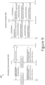
- Figure 9 further illustrates hierarchy Level Update procedures 900 for updating for example Root AP with the new Node, in accordance with embodiments.
- a New Node which is Node STA, may decide to connect to one of the Relay Node AP or Root AP after completing the scanning process.
- the Serving AP (Relay or Root) updates the New Node on the Hierarchy Level and accordingly the New Node is updated with its own ID and capabilities (e.g. STA only or Relay Node).
- the Roaming Node In case the Roaming Node is a Relay Node with Nodes behind (behind meaning that Relay Node has its own Childs / STA connected as a result of the roaming, in cases of new entry process, it is not possible to have any connected devices behind the New STA/Relay), then the Roaming Node updates all connected Relay Nodes IDs and their new Hierarchy Level. The update messages are propagated over the Relay Nodes in the Tree-Mesh Cluster toward the Root AP. In accordance with embodiments, the Roaming Relay Node updates all Nodes behind it, e.g.
- the New Relay Node updates its associated STAs (and Relays) with a new Hierarchy Level, as it changed the location within the Cluster or roamed from other Cluster with their new Hierarchy Levels within the Cluster and accordingly all nodes are synchronized to the Multi-Frame and get the Cluster broadcast information through the broadcast announcement (e.g. Beacon) in the Maintenance Framing Slot.
- the broadcast announcement e.g. Beacon
- the Nodes behind the New Relay are updated with their new Hierarchy and other essential information from the Broadcast message sent during Maintenance Framing Slot.
- the Nodes behind the New Relay are updated with their new Hierarchy and other essential information from the Broadcast message sent during Maintenance Framing Slot.
- the Root AP and all Nodes of the Cluster are aware of the changes resulting from the New Node entry.
- the Serving Node AP (Relay or Root), to which the Node was connected, should propagate the change toward Root AP. Accordingly Root AP updates the Tree Mesh Cluster. This procedure is mostly relevant for Relay Nodes, but the present invention is not limited to any Node within the cluster.
- the Cluster has common identification (ID), meaning that the Nodes (e.g. all Node)s within the Cluster have the same ID.
- service set identifier can be used as a common cluster ID.
- SSID can be shared also with multiple Clusters within the same network.
- a unique ID may be used per each Cluster as well.
- each Node AP (Root or Relay) includes also its own ID.
- BSSID Basic Service Set Identifier
- the procedures of updating the Root AP and the Cluster with the new Node/ Roaming Node and disconnected Node may use the Hierarchy Level distribution procedure.
- FIG. 9 shows hierarchy level updating method 900, in accordance with embodiments.
- Method 900 comprises updating Each Node connected to the specific Cluster with the Hierarchy Level.
- Hierarchy Level update is required so any new Relay STA will get the right scheduling allocation per Node Group.
- the update procedure may be done by different methods as follows:
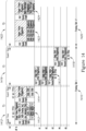
- FIG 10 shows an LTE Framing Structure 1000, which may be used by the present invention methods and systems as shown for example in Figure 7A or Figure 8 for Tree Mesh Cluster Scheduling in a Tree-Mesh Network, in accordance with embodiments.
- the LTE Framing Structure 1000 comprises a Multi-Frame 1002, which may comprise for example 30 sub-frames and accordingly 60 slots. Within the Multi-Frame 1002 each sub-frame is numbered. It is stressed that any numbering method may be used and accordingly any number of sub-frames per Multi-Frame may be used.
- each slot has multiple RBs (Resource Blocks as defined in 3GPP) and each RB or set of RBs and multiple slots can be allocated per UE enabling very flexible OFDMA UE allocation.
- RBs Resource Blocks as defined in 3GPP
- each Sub-Frame or slot can be used for DL or UL transmission.
- LTE and 5G NR has different DL and UL profiles, where 5G NR is much more flexible, still the present invention may be utilized for any profile flexibility.
- the number of DL and UL sub-frames or slots or symbols per frame (e.g. 10 msec) defines the relation between DL and UL, which is equivalent for TDD DL:UL split ratio.
- all eNBs and UEs use the same TDD split and the same DL and UL transmission slots to minimize interference within the radio network.
- LTE/5G wireless systems typically two different modems are used for gNB and UE sides.
- the present invention is relevant for LTE/5G since even with two radios self-interference cancellation is required when using the same RF channel or closed RF channels (e.g. adjacent).
- LTE/5G NR Relay architecture 1100 includes a UE model which is connected to higher hierarchy eNB and eNB module, which serves the next hierarchy UEs.
- MAC and Network Processor Module is used to coordinate between UE and eNB module.
- MAC and Network Processor Module is responsible for forwarding the packets, enabling protocol control functions of MAC and high layers as defined by 3GPP.
- An example for 3GPP Relay Node is IAB (Integrated Access-Backhaul) units, which includes UE and eNB function within the same network location. Such IAB enables link extension using chain configuration.
- the present invention enables IAB units to establish flexible tree-mesh topologies using a single channel or limited number of overlapping channels and avoiding Intra-Node Interference effect.
- Figure 12 shows an example of a tree-mesh Relay Node Groups mapping 1200 of DL and UL slots using LTE Multi-Frame structure 1250 to enable different Relay Nodes in Tree Mesh Cluster 1201 to communicate with each other for different Hierarchical Levels and avoiding intra-node interference, in accordance with embodiments. While Figure 7A shows an example of 802.11 synchronized framing approach Figure 12 shows a similar concept using LTE structure, both in accordance with embodiments.
- the Multi-Frame 1250 includes using one of the slots such as the first Slot 1251to send information about the Node Group mapping structure per one or more Multi-Frames.
- the slot, which holds the broadcast information may be used for regular DL transmission (e.g. where regular DL transmission means 'no maintenance' but rather regular data packet to the associated UEs / Relay). It is considered, that Broadcast information is not big enough and therefore remained resources can be used for regular communication similarly "white slots") as well in other RBs (if available) to all Hierarchy 0 nodes / UEs. Broadcast information can be avoided per Multi-Frame if no change Relay Node Group allocations in the following Multi-Frame.
- the description in the present invention refers to a Multi-Frame using 16 Framing Slots with 2msec per Framing Slot such as in 802.11.
- the invention is not limited to the specific number and Framing slot duration within the Framing Slot or specific wireless standard and system.
- the invention description refers to 802.11 OFDMA-based technology, but not limited to OFDMA provided frequency and time domain wireless resource allocation flexibility between AP and associated STAs, which is very efficient for PTMP (Point-To-Multi-Point) communication topologies.
- This invention has the advantage of using OFDMA, but also may use other wireless methods; e.g. OFDM/TDMA in case it is structured as Multi-Frame (as shown in Figure 2 )
- This invention is relevant also for other synchronized framed schedulers as used in WiMAX, LTE,5GNR and other future synchronized PTMP communication methods (e.g. future 3GPP Releases).
- This text explains how the grouping approach as described in this invention can be applied on TDD LTE and 5GNR implementations.
- this invention also can be relevant for any future wireless technologies if synchronized frames structure is used.
- the LTE & 5GNR PHY structure consists of 1ms sub-frame, while 10 sub-frames formats 10msec frame.
- Such frame in LTE & 5G is used for periodic PHY procedures as defined by 3GPP.
- Each frame consists of multiple slots, while a number of slots depends on the numerology as defined in 5GNR.
- the example in the detailed description refers to LTE PHY structure case.
- LTE includes only one numerology of two slots per sub-frame of 1msec and each slot has 7 OFDM symbols in time (NOTE: 5GNR has some differences in terminologies and number of symbols, but for this invention the approach of grouping is similar).
- the OFDMA structure of LTE & 5G is based on Resource Blocks (RBs), where each RB can be allocated per UE (User Equipment - equivalent to STA in 802.11). Each RB is constructed from 12 subcarriers and 7 symbols (slot in LTE). If referring to LTE TDD structure some sub-frames may be used for DL transmission and others for UL, in 5GNR DL and UL transmissions can be done per symbol basis (based on 3GPP profile).
- Figure 13 , Figure 14 , Figure 15 , Figure 16 , Figure 17 show examples of Framing Slot and Multi-Frame Synchronized structure for 802.11 OFDMA as illustrated by the current applicant U.S. Provisional Application Ser. No. 63/246,863 filed on September 22, 2021 , entitled "SYNCHRONIZED FRAMING SCHEDULER METHODS AND SYSTEMS FOR OFDMA BASED WIRELESS SYSTEMS" (attorney docket no. CM001/USP) which is incorporated herein by reference in its entirety and which may be used as a reference for 802.11 system Tree Mesh scheduling in accordance with the present invention and embodiments.
- Figure 13 shows a Framing Slot structure and scheduling method and system 1300 for OFDMA based wireless systems such as IEEE 802.11 standard, in accordance with embodiments.
- each network may comprise an access point (AP) and a plurality of stations (e.g. STAs A1, A2..An) in 802.11 OFDMA wireless communication system.
- AP access point
- STAs A1, A2..An stations
- 802.11 OFDMA wireless communication system 802.11 OFDMA wireless communication system.
- the AP synchronizes the plurality of STAs within each network using one or more synchronization signals over the air (e.g. using Timestamps) delivered between the AP and the STAs.
- the method includes allocating one or more Framing Slots, such as Framing Slot 1302 and Framing Slot 1303.
- Each Framing Slot (e.g. Framing Slot i, Framing Slot i+1...), comprises a fixed time duration (e.g. 2 msec).
- the Framing Slot's time duration may vary per traffic characteristics (e.g. latency, throughput, etc.).
- each Framing Slot such as Framing Slot 1302 comprises DL and UL transmission periods 1304 and 1306.
- the AP e.g. AP A
- may transmit datagrams e.g. Data STA1, Data STA A2, Data STA3 to multiple STAs (e.g. A1, A2, A3) using for example one or more Data Units such as Data Units 1305 (e.g. HE MU-PPDU 802.11 frame) in the DL direction.
- Data Units 1305 e.g. HE MU-PPDU 802.11 frame
- the Framing Slot structure further defines, in accordance with embodiments, a piggyback mechanism, where part of RUs is used for Trigger Frame 1308 for UL RU allocation and part of RUs is used for Block Ack messages 1309 for previous Framing Slots for non-allocated STAs (e.g. STA 4 and 5).
- each Framing Slot is numbered 0, 1, .. i, i+1 and Guard Time intervals 810 are included between each DL and UL transmission to compensate on the two-way signal propagation time over the air between AP and associated STAs.
- the defined allocations such as Framing Slot 802 include a number of time slots in which each time slot is scheduled as follows:
- the DL and UL transmission periods 1304 and 1306 included in the Framing Slot may have different time durations and the duration ratio between them defines TDD split.
- the network system may provide DL and UL or symmetric oriented services.
- the synchronized scheduling method and system in accordance with embodiments provide managed DL and UL with continuous behavior, hence, bursts (such as Data Units 1305 and 1307) are transmitted continually one burst following the previous burst, while prior 802.11 schedulers provide opportunistic (e.g. not managed and not continuous) DL and UL scheduling transmissions opportunities.
- the framing structure as described in accordance with embodiments includes one or more DL transmission bursts such as DL Data Unit 1305 (e.g. HE MU-PPDU) during the fixed-time DL period 804 and UL transmission bursts such as UL Data Unit 1307 (e.g. HE TB PPDU) during fixed-time UL period 1306.
- DL Data Unit 1305 e.g. HE MU-PPDU
- UL transmission bursts such as UL Data Unit 1307 (e.g. HE TB PPDU) during fixed-time UL period 1306.
- the first burst is transmitted by AP at the beginning of each Framing Slot. If more than one DL burst is transmitted during the DL period (as illustrated for example in Figure 10 ) the following DL bursts are transmitted with a time offset from the beginning of the Framing Slot as per AP scheduling decision. The total time for all DL bursts transmissions will not exceed the fixed-time DL period 1304.
- the STAs transmit to the AP a first burst (Data Unit 807 such as HE TB PPDU) at the beginning of the UL period within the Framing Slot 1302. If more than one UL burst is transmitted by another set of STAs within the UL period of the Framing Slot (as illustrated in Figure 14 ), these bursts should be transmitted with time-offset from the beginning of the UL period as indicated by AP to the STAs during the DL period. The total time for all UL bursts transmissions will not exceed the fixed-time UL period.
- Data Unit 807 such as HE TB PPDU
- the fixed-time Framing Slots are transmitted constantly, while AP and STAs are completely synchronized one with the other on the same transmission timings, transmission durations and numbering sequence of the Framing Slots.
- a Group of Framing Slots generates a Multi-Frame as explained hereinafter with respect to Figure 15A, Figure 15B and Figure 15C .
- each Framing Slot may support one or more Data Units (e.g. PPDU frames) per each DL transmission and each UL transmission. While Figure 13 shows an example of a single Data Unit (e.g. PPDU frame) per DL transmission and UL transmission (for explanation simplicity), Figure 14 shows an example including two Data Units in DL and two Data Units in UL per Framing Slot.
- the number and duration of Data Units in DL and UL slots can vary as long as the total time duration of data units is not exceeding the DL and UL time duration as set by TDD split in the system.
- the systems and methods in accordance with embodiments may define scheduling methods and systems configured and enabled for transmitting/receiving multiple Data Units (such as 802.11ax HE MU-PPDU) per Framing Slot in each DL and UL directions.
- multiple Data Units such as 802.11ax HE MU-PPDU
- Each Framing Slot such as Framing Slot 1410 includes a DL transmission period 1412 and UL transmission period 1416.
- the DL transmission period 1412 and UL transmission period 1416 comprise respectively one or more DL Data Unit bursts and one or more UL Data Unit bursts such as DL Data Unit bursts 1413 and 1414 (e.g. HE MU PPDU) and UL Data unit bursts 1417 and 1418 (e.g. HE TB PPDU).
- each Data Unit Burst may have a different time length based on the AP scheduling decision, but the total time length of all transmission bursts cannot exceed the fixed DL period time.
- different Data Units may allocate RU to a different set of Data Units, and/or the same STAs may belong to a different set of STAs.
- STA1 may be in the first Data Unit 1413 and also in the second Data Unit 1014.
- AP in operation AP, such AP A, transmits one or more DL Data Unit bursts (Data Units 1413 and 1414) to one or more STAs (STA1, STA2, STA3 , TA4 and STA5) during DL transmission period 1412.
- Each DL Data Unit burst comprises:
- STAs which are communicating with AP (Such AP A) and which received UL transmission instructions in Trigger Frame during the DL transmission period send UL Data Unit Bursts 1417 and 1418 (such as 802.11ax HE TB-PPDU ) during the UL transmission period (e.g. UL transmission period 1416) as allocated in accordance with embodiments, as follows:
- Figure 14 presents example of two Data Units (e.g. two PPDUs) per Framing Slot
- the systems, devices and methods, in accordance with embodiments may include any combination of Data Units per Framing Slot.
- the Data Units time duration can vary, but is limited to the DL and UL periods, which are fixed in the synchronized network.
- Multi-Frame structure as defined in accordance to embodiments, includes multiple Framing Slots. Examples of Multi Frames are illustrated in Figure 15A, Figure 15B and Figure 15C .
- a Multi-Frame for OFDMA based wireless systems such as IEEE 802.11 standard for wireless local-area networks.
- the Multi-Frame comprises multiple Framing Slots, for example, a predefined group of Framing Slots.
- the Multi-Frame comprises consequent Framing Slots, where AP and STAs are synchronized, respectively, one with the others by having common (e.g. same) timing to identify the beginning and end of the Multi-frame. Additionally, AP and STAs are both synchronized one with the others with shared Framing Slot ordering and numbering within the Multi-Frame.
- one or more Multi-Frames may be transmitted continuously one after the other.
- one, some, or all Framing Slots of the Multi-Frame may be the Framing Slot 802 shown in Figure 13 or Framing Slot 1410 shown in Figure 14 .
- the numbering of Framing Slots is circulated per Multi-Frame size.
- FIG. 15A shows, in accordance with embodiments, a plurality of Multi-Frames 1501 (e.g. Multi Frame i, Multi Frame i +1) and Multi Frame structure, in accordance with embodiments.
- Multi-Frames 1501 e.g. Multi Frame i, Multi Frame i +1
- Multi Frame structure in accordance with embodiments.
- Each Multi-Frame may comprise for example 16 Framing Slots. It is stressed that the Multi-Frame structure may include any number of Framing Slots, for example, more or less than 16 Framing Slots.
- one or more of the Framing Slots of each Multi-Frame may be used as Maintenance Framing Slot such as Framing Slot 1510 and 1510' (slot numbered '0').
- the Maintenance Framing Slot time duration is equivalent to each of the other fixed Frame Slots (slots '1'- '15') time duration in the Multi-Frame.
- the time duration of the Maintenance Framing Slot 1510 and other Framing Slots is the same.
- the Maintenance Framing Slot 1510 is numbered '0' and located at the beginning of Multi-Frame 1500.
- the Multi-Frame 1500 total time duration and number of Framing Slots may vary between different Multi-Frames, hence, the time duration of a Multi-Frame is determined according to the number of Framing Slots in the Mult-Frame.
- the Multi-Frame duration can be broadcasted by AP to all STAs by the Maintenance Framing Slot 1510 in a Multi-Frame for the following Multi-Frames to synchronize Framing Slot sequence (e.g. numbering) between AP and STAs.
- FIG. 15B shows a Maintenance Framing Slot 1512 (in Synchronous Mode) comprising Long BF Training and Figure 15C shows a Maintenance Framing Slot (Synchronous Mode) 1522 w/o BF Training.
- the Maintenance Framing Slot 1512 may comprise, in accordance with embodiments, a Beacon message 1513 for broadcasting specific network information as described hereinbelow and optionally also Beamforming Training procedure. When no Beamforming training procedure exists, the Maintenance Slot 1512 includes DL and UL PPDU following the Beacon message.
- the numbering in the Maintenance Framing Slot 1512 relates to the typical OFDM symbols numbers needed to transmit DL broadcast message (e.g. Beacon message) and Beamforming training messages sequence.
- the Multi-Frame structure in accordance with embodiments, supports the following capabilities:
- Maintenance Framing Slot is used, in accordance with embodiments, by the AP/BST for the Framing Slot scheduling profile announcement and other 802.11 broadcasting information (such as SSID (Service Set Identifier) broadcasting in according to 802.11).
- 802.11 broadcasting information such as SSID (Service Set Identifier) broadcasting in according to 802.11.
- Such announcements can be broadcasted using for example 802.11 Beacon message.
- the Framing Slot scheduling profile information includes (but not limited to), in accordance with embodiments:
- the Maintenance Framing Slot structure as shown in Figure 14B may be divided to transmission bursts (based on the typical OFDM symbols numbering) as follows:
- the Maintenance Framing Slot structure as shown in Figure 14C may be divided to transmission bursts (based on the typical OFDM symbols numbering) as follows:
- the structure of the Maintenance Framing Slot is mandatory however the number of symbols per each OFDM burst can vary.
- the methods, devices and systems in accordance with embodiments may use a Semi-Synchronous Multi-Frame structure which is a subset of the fully synchronous Framing Scheduler.
- the Semi-Synchronous Multi-Frame structure may be applicable for small networks (limited number of APs per network), where DL and UL transmission synchronization is not essential for inter-cell interference avoidance. Such deployment does not require a synchronization source (like as GPS or IEEE 1588).
- Another advantage of the Semi-Synchronous Multi-Frame structure is R&D implementation simplicity, where most of standard 802.11ax procedures can be used as is.
- the Semi-Synchronous Multi-Frame structure is suitable for example for unlicensed bands, where regulation requires LBT.
- FIG. 16 shows a plurality of Multi-Frames 1601 and a Multi-Frame structure 1600 for non-synchronized network, in accordance with embodiments.
- the Multi-Frame structure 1600 includes Maintenance Framing Slot 1610, which don't have a fixed time i.e. Maintenance Framing Slot 1610 may have different time durations than the other fixed time/regular Framing Slots (slots '0'-'15') and therefore must be transmitted before the regular Framing Slots are performed. Since this structure is not network synchronized it may include CSMA/CA timers (e.g. DIFS and Backoff) prior to any Multi-Frame.
- This Multi-Frame structure enables using NAV mechanism as defined in 802.11 using MU RTS/CTS messages and TXOP field.
- the Maintenance Framing Slot 1610 includes:
- FIG 17 shows an example of a Framing Slot 1700, which can be used for Semi-Synchronous Multi-Frame procedure, for OFDMA based wireless systems such as IEEE 802.11 standard, in accordance with embodiments.
- the Framing Slot 1700 may reuse the procedures as defined in 802.11ax.
- the Framing Slot 1700 for semi-synchronized scheduler comprises, in accordance with embodiments, DL and UL procedures- DL procedure 1710 includes Data Unit 1712 (e.g. HE MU-PPDU) signaled by AP toward STAs and in response an acknowledgment message Data unit 1414 (ACK/Block Ack in HE TB PPDU) from STAs toward AP.
- UL procedure 1720 includes Trigger Frame 1425 sent by AP toward STAs in order to instruct and synchronize regarding simultaneous UL transmission from STAs. Following Trigger Frame 1725, the STAs send Data Units 1726 (e.g. HE TB-PPDU) toward AP.
- AP responds with an acknowledgment (Block ACK) toward STAs.
- Block ACK acknowledgment
- Each duration of DL and UL procedures can vary in time, however, in accordance with embodiments, the combined DL and UL procedures within the Framing Slot are fixed in time (e.g. 2 msec) and predefined.
- the semi-synchronous Framing Slot 1700 may include using piggyback approach for Trigger Frame and acknowledgment information as defined for Synchronized Framing Slot as shown in Figure 13 and Figure 14 , however, between each 802.11 PPDU the system should keep SIFS 1730 timers and consider the SIFS periods as part of the semi-synchronized Framing Slot total duration.
- the present invention refers to any OFDMA based systems and networks such as 802.11 standard releases for example 802.11ax.
- the present invention refers to any OFDMA based systems and networks such as 802.11 standard releases for example 802.11ax.
- the processing unit may be a digital processing device including one or more hardware central processing units (CPU) that carry out the device's functions.
- the digital processing device further comprises an operating system configured to perform executable instructions.
- the digital processing device is optionally connected to a computer network.
- the digital processing device is optionally connected to the Internet such that it accesses the World Wide Web.
- the digital processing device is optionally connected to a cloud computing infrastructure.
- the digital processing device is optionally connected to an intranet.
- the digital processing device is optionally connected to a data storage device.
- Suitable tablet computers include those with booklet, slate, and convertible configurations, known to those of skill in the art.
- the digital processing device includes an operating system configured to perform executable instructions.
- the operating system is, for example, software, including programs and data, which manages the device's hardware and provides services for execution of applications.
- the digital processing device includes an input device to receive information from a user.
- the input device is a keyboard.
- the input device is a pointing device including, by way of non-limiting examples, a mouse, trackball, track pad, joystick, game controller, or stylus.
- the input device is a touch screen or a multi-touch screen.
- the input device is a microphone to capture voice or other sound input.
- the input device is a video camera to capture motion or visual input.
- the input device is a combination of devices such as those disclosed herein.
- a computer program comprises one sequence of instructions. In some embodiments, a computer program comprises a plurality of sequences of instructions. In some embodiments, a computer program is provided from one location. In other embodiments, a computer program is provided from a plurality of locations. In various embodiments, a computer program includes one or more software modules. In various embodiments, a computer program includes, in part or in whole, one or more web applications, one or more mobile applications, one or more standalone applications, one or more web browser plug-ins, extensions, add-ins, or add-ons, or combinations thereof. In some embodiments, a computer program includes a mobile application provided to a mobile digital processing device. In some embodiments, the mobile application is provided to a mobile digital processing device at the time it is manufactured. In other embodiments, the mobile application is provided to a mobile digital processing device via the computer network described herein.
- the system disclosed herein includes software, server, and/or database modules, or use of the same.
- software modules are created by techniques known to those of skill in the art using machines, software, and languages known to the art.
- the software modules disclosed herein are implemented in a multitude of ways.
- a software module comprises a file, a section of code, a programming object, a programming structure, or combinations thereof.
- a software module comprises a plurality of files, a plurality of sections of code, a plurality of programming objects, a plurality of programming structures, or combinations thereof.
- the one or more software modules comprise, by way of non-limiting examples, a web application, a mobile application, and a standalone application.
- software modules are in one computer program or application. In other embodiments, software modules are in more than one computer program or application. In some embodiments, software modules are hosted on one machine. In other embodiments, software modules are hosted on more than one machine. In further embodiments, software modules are hosted on cloud computing platforms. In some embodiments, software modules are hosted on one or more machines in one location. In other embodiments, software modules are hosted on one or more machines in more than one location.
Landscapes
- Engineering & Computer Science (AREA)
- Computer Networks & Wireless Communication (AREA)
- Signal Processing (AREA)
- Mobile Radio Communication Systems (AREA)
Applications Claiming Priority (2)
| Application Number | Priority Date | Filing Date | Title |
|---|---|---|---|
| US202163247027P | 2021-09-22 | 2021-09-22 | |
| US202163246863P | 2021-09-22 | 2021-09-22 |
Publications (3)
| Publication Number | Publication Date |
|---|---|
| EP4156824A1 true EP4156824A1 (fr) | 2023-03-29 |
| EP4156824C0 EP4156824C0 (fr) | 2025-08-13 |
| EP4156824B1 EP4156824B1 (fr) | 2025-08-13 |
Family
ID=83318795
Family Applications (1)
| Application Number | Title | Priority Date | Filing Date |
|---|---|---|---|
| EP22195517.2A Active EP4156824B1 (fr) | 2021-09-22 | 2022-09-14 | Procédés et systèmes de planification de trames synchronisées pour réseaux maillés en arbre sans fil |
Country Status (2)
| Country | Link |
|---|---|
| US (1) | US12490253B2 (fr) |
| EP (1) | EP4156824B1 (fr) |
Citations (3)
| Publication number | Priority date | Publication date | Assignee | Title |
|---|---|---|---|---|
| RU80211U1 (ru) | 2008-10-29 | 2009-01-27 | Московское Государственное Унитарное Предприятие "Мосводоканал" | Универсальный поплавковый наполнительный клапан |
| US20160073429A1 (en) * | 2013-05-03 | 2016-03-10 | Interdigital Patent Holdings, Inc. | Systems and methods for fractional carrier sense multiple access with collision avoidance (csma/ca) for wlans |
| US20190364453A1 (en) * | 2013-02-07 | 2019-11-28 | Idac Holdings, Inc. | Interference measurements and management in directional mesh networks |
Family Cites Families (25)
| Publication number | Priority date | Publication date | Assignee | Title |
|---|---|---|---|---|
| US8599822B2 (en) | 2005-03-23 | 2013-12-03 | Cisco Technology, Inc. | Slot-based transmission synchronization mechanism in wireless mesh networks |
| US7706249B2 (en) | 2006-02-08 | 2010-04-27 | Motorola, Inc. | Method and apparatus for a synchronization channel in an OFDMA system |
| KR101605326B1 (ko) | 2010-02-26 | 2016-04-01 | 엘지전자 주식회사 | 신호 송수신 방법 및, 그를 위한 기지국 및 사용자기기 |
| US8559464B2 (en) * | 2010-04-30 | 2013-10-15 | International Business Machines Corporation | Synchronizing nodes of a multi-hop network |
| KR102166184B1 (ko) * | 2012-11-30 | 2020-10-15 | 한국전자통신연구원 | 무선랜 시스템에서의 자원 할당 방법, 무선랜 시스템 |
| CN105340350B (zh) * | 2013-07-02 | 2019-03-22 | Kt株式会社 | 在无线lan系统中的信道接入方法及装置 |
| US9800501B2 (en) | 2013-08-28 | 2017-10-24 | Qualcomm Incorporated | Methods and apparatus for multiple user uplink |
| US9882701B2 (en) * | 2013-12-04 | 2018-01-30 | Electronics And Telecommunications Research Institute | Method and apparatus for allocating channel in wireless local area network |
| CN106605382B (zh) | 2014-08-27 | 2020-11-06 | Lg 电子株式会社 | 在无线通信系统中的发送数据的方法及用于其装置 |
| US9742543B2 (en) | 2014-09-23 | 2017-08-22 | Newracom, Inc. | Acknowledgment mechanisms for OFDMA operation |
| US10531433B2 (en) | 2014-10-29 | 2020-01-07 | Qualcomm Incorporated | Methods and apparatus for multiple user uplink access |
| US9756626B2 (en) | 2014-11-13 | 2017-09-05 | Intel IP Corporation | High-efficiency Wi-Fi (HEW) station and access point (AP) and method for signaling of channel resource allocations |
| US20180263047A1 (en) | 2014-12-25 | 2018-09-13 | Lg Electronics Inc. | Method and apparatus for transmitting data unit on basis of trigger frame |
| CN107251449B (zh) | 2015-03-27 | 2021-09-28 | 英特尔公司 | 802.11ax标准中用于基于ofdma的功率控制的帧结构设计和系统 |
| WO2016167431A1 (fr) | 2015-04-16 | 2016-10-20 | 엘지전자(주) | Procédé de transmission de données dans un système de communication sans fil et dispositif correspondant |
| US10057021B2 (en) | 2015-04-24 | 2018-08-21 | Ubiquiti Networks, Inc. | Resource allocation in a wireless communication system |
| US10181930B2 (en) | 2015-05-10 | 2019-01-15 | Newracom, Inc. | Multiplexing acknowledgment messages in response to downlink frames |
| US10264597B2 (en) | 2015-07-17 | 2019-04-16 | Ondas Networks Inc. | Method and system for best effort scheduling for a point to multipoint broadband wireless system |
| EP3338493A1 (fr) * | 2015-08-21 | 2018-06-27 | Linear Technology Corporation | Réseau maillé sans fil à multiples points d'accès |
| GB2549967A (en) | 2016-05-04 | 2017-11-08 | Canon Kk | Improved reservation of channels in an 802.11AX network |
| US10701727B2 (en) * | 2017-07-13 | 2020-06-30 | Qualcomm Incorporated | Techniques and apparatuses for resource management for a wireless network |
| US10911120B2 (en) | 2017-07-24 | 2021-02-02 | Qualcomm Incorporated | Downlink (DL) coordinated beamforming protocols for WiFi |
| FI20185326A1 (en) | 2018-04-06 | 2019-10-07 | Nokia Technologies Oy | Monitoring in wireless backhaul networks |
| US11490390B2 (en) | 2019-08-28 | 2022-11-01 | Qualcomm Incorporated | Enhanced resource management for mobile integrated access backhaul (IAB) |
| US11627526B2 (en) * | 2019-12-02 | 2023-04-11 | Qualcomm Incorporated | Coordinated device-to-device communications |
-
2022
- 2022-09-14 EP EP22195517.2A patent/EP4156824B1/fr active Active
- 2022-09-21 US US17/933,967 patent/US12490253B2/en active Active
Patent Citations (3)
| Publication number | Priority date | Publication date | Assignee | Title |
|---|---|---|---|---|
| RU80211U1 (ru) | 2008-10-29 | 2009-01-27 | Московское Государственное Унитарное Предприятие "Мосводоканал" | Универсальный поплавковый наполнительный клапан |
| US20190364453A1 (en) * | 2013-02-07 | 2019-11-28 | Idac Holdings, Inc. | Interference measurements and management in directional mesh networks |
| US20160073429A1 (en) * | 2013-05-03 | 2016-03-10 | Interdigital Patent Holdings, Inc. | Systems and methods for fractional carrier sense multiple access with collision avoidance (csma/ca) for wlans |
Also Published As
| Publication number | Publication date |
|---|---|
| EP4156824C0 (fr) | 2025-08-13 |
| EP4156824B1 (fr) | 2025-08-13 |
| US20230086686A1 (en) | 2023-03-23 |
| US12490253B2 (en) | 2025-12-02 |
Similar Documents
| Publication | Publication Date | Title |
|---|---|---|
| US10148369B2 (en) | System and method for timing alignment of LTE cells and inter-operator co-existence on unlicensed spectrum | |
| CN110650443B (zh) | 干扰管理方法及接入点 | |
| EP2451226B1 (fr) | Procédé, appareil et système de synchronisation d'interface radio | |
| US9226312B2 (en) | Resource management system and method for inter-cell interference coordination in wireless communication system | |
| CN105122917B (zh) | 动态tdd配置用户设备和方法 | |
| JP7017637B2 (ja) | システム情報監視 | |
| TWI702882B (zh) | 無線通訊方法和無線通訊設備 | |
| CN113206728A (zh) | 用于无线通信系统中的系统信息传递的方法和装置 | |
| US9420485B2 (en) | Frame structure and signaling arrangement for interference aware scheduling | |
| JP2020537425A (ja) | デュアルrat通信のための時分割多重化のための技法および装置 | |
| WO2015017999A1 (fr) | Procédé et dispositif de transmission et de réception d'informations | |
| US10972990B2 (en) | System information rate matching | |
| CA2828070A1 (fr) | Extension d'affectation de porteuses par l'utilisation de porteuses de composants dynamiques | |
| JP2021505043A (ja) | 5gネットワークにおけるキャリア情報シグナリング | |
| JP2021514148A (ja) | 物理リソースブロックバンドルサイズ選択 | |
| US11903017B2 (en) | Wireless network configuration for low-latency applications | |
| US20250168883A1 (en) | Synchronized framing scheduling methods and systems for ofdma based wireless systems | |
| CN103458512A (zh) | 小区上下行时隙配比配置方法、装置、基站设备及系统 | |
| US10028298B2 (en) | System and method for indicating periodic allocations | |
| EP4156824B1 (fr) | Procédés et systèmes de planification de trames synchronisées pour réseaux maillés en arbre sans fil | |
| JP6794389B2 (ja) | 情報送信及び受信方法及びデバイス | |
| JP6549743B2 (ja) | 情報送信及び受信方法及びデバイス | |
| JP2019180100A (ja) | 情報送信及び受信方法及びデバイス |
Legal Events
| Date | Code | Title | Description |
|---|---|---|---|
| PUAI | Public reference made under article 153(3) epc to a published international application that has entered the european phase |
Free format text: ORIGINAL CODE: 0009012 |
|
| STAA | Information on the status of an ep patent application or granted ep patent |
Free format text: STATUS: THE APPLICATION HAS BEEN PUBLISHED |
|
| AK | Designated contracting states |
Kind code of ref document: A1 Designated state(s): AL AT BE BG CH CY CZ DE DK EE ES FI FR GB GR HR HU IE IS IT LI LT LU LV MC MK MT NL NO PL PT RO RS SE SI SK SM TR |
|
| STAA | Information on the status of an ep patent application or granted ep patent |
Free format text: STATUS: REQUEST FOR EXAMINATION WAS MADE |
|
| 17P | Request for examination filed |
Effective date: 20230929 |
|
| RBV | Designated contracting states (corrected) |
Designated state(s): AL AT BE BG CH CY CZ DE DK EE ES FI FR GB GR HR HU IE IS IT LI LT LU LV MC MK MT NL NO PL PT RO RS SE SI SK SM TR |
|
| GRAP | Despatch of communication of intention to grant a patent |
Free format text: ORIGINAL CODE: EPIDOSNIGR1 |
|
| STAA | Information on the status of an ep patent application or granted ep patent |
Free format text: STATUS: GRANT OF PATENT IS INTENDED |
|
| INTG | Intention to grant announced |
Effective date: 20250313 |
|
| GRAS | Grant fee paid |
Free format text: ORIGINAL CODE: EPIDOSNIGR3 |
|
| GRAA | (expected) grant |
Free format text: ORIGINAL CODE: 0009210 |
|
| STAA | Information on the status of an ep patent application or granted ep patent |
Free format text: STATUS: THE PATENT HAS BEEN GRANTED |
|
| AK | Designated contracting states |
Kind code of ref document: B1 Designated state(s): AL AT BE BG CH CY CZ DE DK EE ES FI FR GB GR HR HU IE IS IT LI LT LU LV MC MK MT NL NO PL PT RO RS SE SI SK SM TR |
|
| REG | Reference to a national code |
Ref country code: GB Ref legal event code: FG4D |
|
| REG | Reference to a national code |
Ref country code: CH Ref legal event code: EP |
|
| REG | Reference to a national code |
Ref country code: DE Ref legal event code: R096 Ref document number: 602022019294 Country of ref document: DE |
|
| REG | Reference to a national code |
Ref country code: IE Ref legal event code: FG4D |
|
| PGFP | Annual fee paid to national office [announced via postgrant information from national office to epo] |
Ref country code: AT Payment date: 20251020 Year of fee payment: 4 |
|
| U01 | Request for unitary effect filed |
Effective date: 20250915 |
|
| U07 | Unitary effect registered |
Designated state(s): AT BE BG DE DK EE FI FR IT LT LU LV MT NL PT RO SE SI Effective date: 20250922 |
|
| U20 | Renewal fee for the european patent with unitary effect paid |
Year of fee payment: 4 Effective date: 20251020 |
|
| PG25 | Lapsed in a contracting state [announced via postgrant information from national office to epo] |
Ref country code: IS Free format text: LAPSE BECAUSE OF FAILURE TO SUBMIT A TRANSLATION OF THE DESCRIPTION OR TO PAY THE FEE WITHIN THE PRESCRIBED TIME-LIMIT Effective date: 20251213 |
|
| PG25 | Lapsed in a contracting state [announced via postgrant information from national office to epo] |
Ref country code: NO Free format text: LAPSE BECAUSE OF FAILURE TO SUBMIT A TRANSLATION OF THE DESCRIPTION OR TO PAY THE FEE WITHIN THE PRESCRIBED TIME-LIMIT Effective date: 20251113 |
|
| PG25 | Lapsed in a contracting state [announced via postgrant information from national office to epo] |
Ref country code: HR Free format text: LAPSE BECAUSE OF FAILURE TO SUBMIT A TRANSLATION OF THE DESCRIPTION OR TO PAY THE FEE WITHIN THE PRESCRIBED TIME-LIMIT Effective date: 20250813 |
|
| PG25 | Lapsed in a contracting state [announced via postgrant information from national office to epo] |
Ref country code: GR Free format text: LAPSE BECAUSE OF FAILURE TO SUBMIT A TRANSLATION OF THE DESCRIPTION OR TO PAY THE FEE WITHIN THE PRESCRIBED TIME-LIMIT Effective date: 20251114 |
|
| PG25 | Lapsed in a contracting state [announced via postgrant information from national office to epo] |
Ref country code: PL Free format text: LAPSE BECAUSE OF FAILURE TO SUBMIT A TRANSLATION OF THE DESCRIPTION OR TO PAY THE FEE WITHIN THE PRESCRIBED TIME-LIMIT Effective date: 20250813 |
|
| PG25 | Lapsed in a contracting state [announced via postgrant information from national office to epo] |
Ref country code: RS Free format text: LAPSE BECAUSE OF FAILURE TO SUBMIT A TRANSLATION OF THE DESCRIPTION OR TO PAY THE FEE WITHIN THE PRESCRIBED TIME-LIMIT Effective date: 20251113 |
|
| PG25 | Lapsed in a contracting state [announced via postgrant information from national office to epo] |
Ref country code: ES Free format text: LAPSE BECAUSE OF FAILURE TO SUBMIT A TRANSLATION OF THE DESCRIPTION OR TO PAY THE FEE WITHIN THE PRESCRIBED TIME-LIMIT Effective date: 20250813 |
|
| PG25 | Lapsed in a contracting state [announced via postgrant information from national office to epo] |
Ref country code: SM Free format text: LAPSE BECAUSE OF FAILURE TO SUBMIT A TRANSLATION OF THE DESCRIPTION OR TO PAY THE FEE WITHIN THE PRESCRIBED TIME-LIMIT Effective date: 20250813 |